EP1450428A2 - Microfuel cell having anodic and cathodic microfluidic channels and related methods - Google Patents
Microfuel cell having anodic and cathodic microfluidic channels and related methods Download PDFInfo
- Publication number
- EP1450428A2 EP1450428A2 EP04250284A EP04250284A EP1450428A2 EP 1450428 A2 EP1450428 A2 EP 1450428A2 EP 04250284 A EP04250284 A EP 04250284A EP 04250284 A EP04250284 A EP 04250284A EP 1450428 A2 EP1450428 A2 EP 1450428A2
- Authority
- EP
- European Patent Office
- Prior art keywords
- anodic
- cathodic
- catalyst
- electrode
- reactant
- Prior art date
- Legal status (The legal status is an assumption and is not a legal conclusion. Google has not performed a legal analysis and makes no representation as to the accuracy of the status listed.)
- Granted
Links
- 238000000034 method Methods 0.000 title claims description 32
- 239000003054 catalyst Substances 0.000 claims abstract description 159
- 239000000376 reactant Substances 0.000 claims abstract description 117
- 239000010410 layer Substances 0.000 claims abstract description 106
- 239000000758 substrate Substances 0.000 claims abstract description 95
- 239000000446 fuel Substances 0.000 claims abstract description 39
- 239000012790 adhesive layer Substances 0.000 claims abstract description 9
- 239000012530 fluid Substances 0.000 claims description 22
- 238000009792 diffusion process Methods 0.000 claims description 17
- OKKJLVBELUTLKV-UHFFFAOYSA-N Methanol Chemical compound OC OKKJLVBELUTLKV-UHFFFAOYSA-N 0.000 claims description 16
- 238000004519 manufacturing process Methods 0.000 claims description 16
- 238000004891 communication Methods 0.000 claims description 14
- 229910052710 silicon Inorganic materials 0.000 claims description 9
- 239000010703 silicon Substances 0.000 claims description 9
- ATUOYWHBWRKTHZ-UHFFFAOYSA-N Propane Chemical compound CCC ATUOYWHBWRKTHZ-UHFFFAOYSA-N 0.000 claims description 6
- 239000001257 hydrogen Substances 0.000 claims description 6
- 229910052739 hydrogen Inorganic materials 0.000 claims description 6
- VNWKTOKETHGBQD-UHFFFAOYSA-N methane Chemical compound C VNWKTOKETHGBQD-UHFFFAOYSA-N 0.000 claims description 6
- 239000001301 oxygen Substances 0.000 claims description 4
- 229910052760 oxygen Inorganic materials 0.000 claims description 4
- OTMSDBZUPAUEDD-UHFFFAOYSA-N Ethane Chemical compound CC OTMSDBZUPAUEDD-UHFFFAOYSA-N 0.000 claims description 3
- QVGXLLKOCUKJST-UHFFFAOYSA-N atomic oxygen Chemical compound [O] QVGXLLKOCUKJST-UHFFFAOYSA-N 0.000 claims description 3
- 239000001273 butane Substances 0.000 claims description 2
- 125000004435 hydrogen atom Chemical class [H]* 0.000 claims description 2
- IJDNQMDRQITEOD-UHFFFAOYSA-N n-butane Chemical compound CCCC IJDNQMDRQITEOD-UHFFFAOYSA-N 0.000 claims description 2
- OFBQJSOFQDEBGM-UHFFFAOYSA-N n-pentane Natural products CCCCC OFBQJSOFQDEBGM-UHFFFAOYSA-N 0.000 claims description 2
- 229920000620 organic polymer Polymers 0.000 claims description 2
- 239000001294 propane Substances 0.000 claims description 2
- 230000008901 benefit Effects 0.000 description 11
- 238000006243 chemical reaction Methods 0.000 description 10
- 239000003792 electrolyte Substances 0.000 description 10
- XUIMIQQOPSSXEZ-UHFFFAOYSA-N Silicon Chemical group [Si] XUIMIQQOPSSXEZ-UHFFFAOYSA-N 0.000 description 8
- 238000010586 diagram Methods 0.000 description 7
- 230000003197 catalytic effect Effects 0.000 description 6
- 238000001816 cooling Methods 0.000 description 5
- -1 typically Substances 0.000 description 3
- 229910000838 Al alloy Inorganic materials 0.000 description 2
- UFHFLCQGNIYNRP-UHFFFAOYSA-N Hydrogen Chemical compound [H][H] UFHFLCQGNIYNRP-UHFFFAOYSA-N 0.000 description 2
- XAGFODPZIPBFFR-UHFFFAOYSA-N aluminium Chemical compound [Al] XAGFODPZIPBFFR-UHFFFAOYSA-N 0.000 description 2
- 229910052782 aluminium Inorganic materials 0.000 description 2
- 238000000151 deposition Methods 0.000 description 2
- 239000007789 gas Substances 0.000 description 2
- PCHJSUWPFVWCPO-UHFFFAOYSA-N gold Chemical compound [Au] PCHJSUWPFVWCPO-UHFFFAOYSA-N 0.000 description 2
- 229910052737 gold Inorganic materials 0.000 description 2
- 239000010931 gold Substances 0.000 description 2
- 150000002431 hydrogen Chemical class 0.000 description 2
- 150000002500 ions Chemical class 0.000 description 2
- 238000012986 modification Methods 0.000 description 2
- 230000004048 modification Effects 0.000 description 2
- 229910021420 polycrystalline silicon Inorganic materials 0.000 description 2
- 229920005591 polysilicon Polymers 0.000 description 2
- 238000006479 redox reaction Methods 0.000 description 2
- 239000007787 solid Substances 0.000 description 2
- 229910052715 tantalum Inorganic materials 0.000 description 2
- GUVRBAGPIYLISA-UHFFFAOYSA-N tantalum atom Chemical compound [Ta] GUVRBAGPIYLISA-UHFFFAOYSA-N 0.000 description 2
- 239000004215 Carbon black (E152) Substances 0.000 description 1
- MYMOFIZGZYHOMD-UHFFFAOYSA-N Dioxygen Chemical compound O=O MYMOFIZGZYHOMD-UHFFFAOYSA-N 0.000 description 1
- 230000015572 biosynthetic process Effects 0.000 description 1
- 239000006227 byproduct Substances 0.000 description 1
- 238000010276 construction Methods 0.000 description 1
- 239000006185 dispersion Substances 0.000 description 1
- 238000003487 electrochemical reaction Methods 0.000 description 1
- 238000005530 etching Methods 0.000 description 1
- 229930195733 hydrocarbon Natural products 0.000 description 1
- 150000002430 hydrocarbons Chemical class 0.000 description 1
- 230000001771 impaired effect Effects 0.000 description 1
- 239000000463 material Substances 0.000 description 1
- 230000003647 oxidation Effects 0.000 description 1
- 238000007254 oxidation reaction Methods 0.000 description 1
- 230000001590 oxidative effect Effects 0.000 description 1
- 238000000059 patterning Methods 0.000 description 1
- 238000002047 photoemission electron microscopy Methods 0.000 description 1
- 229920001483 poly(ethyl methacrylate) polymer Polymers 0.000 description 1
- 239000004065 semiconductor Substances 0.000 description 1
- 239000002356 single layer Substances 0.000 description 1
- XLYOFNOQVPJJNP-UHFFFAOYSA-N water Substances O XLYOFNOQVPJJNP-UHFFFAOYSA-N 0.000 description 1
Images


Classifications
-
- H—ELECTRICITY
- H01—ELECTRIC ELEMENTS
- H01M—PROCESSES OR MEANS, e.g. BATTERIES, FOR THE DIRECT CONVERSION OF CHEMICAL ENERGY INTO ELECTRICAL ENERGY
- H01M4/00—Electrodes
- H01M4/86—Inert electrodes with catalytic activity, e.g. for fuel cells
- H01M4/8605—Porous electrodes
- H01M4/8626—Porous electrodes characterised by the form
-
- H—ELECTRICITY
- H01—ELECTRIC ELEMENTS
- H01M—PROCESSES OR MEANS, e.g. BATTERIES, FOR THE DIRECT CONVERSION OF CHEMICAL ENERGY INTO ELECTRICAL ENERGY
- H01M8/00—Fuel cells; Manufacture thereof
- H01M8/02—Details
- H01M8/0202—Collectors; Separators, e.g. bipolar separators; Interconnectors
- H01M8/0247—Collectors; Separators, e.g. bipolar separators; Interconnectors characterised by the form
-
- H—ELECTRICITY
- H01—ELECTRIC ELEMENTS
- H01M—PROCESSES OR MEANS, e.g. BATTERIES, FOR THE DIRECT CONVERSION OF CHEMICAL ENERGY INTO ELECTRICAL ENERGY
- H01M8/00—Fuel cells; Manufacture thereof
- H01M8/10—Fuel cells with solid electrolytes
- H01M8/1007—Fuel cells with solid electrolytes with both reactants being gaseous or vaporised
-
- H—ELECTRICITY
- H01—ELECTRIC ELEMENTS
- H01M—PROCESSES OR MEANS, e.g. BATTERIES, FOR THE DIRECT CONVERSION OF CHEMICAL ENERGY INTO ELECTRICAL ENERGY
- H01M8/00—Fuel cells; Manufacture thereof
- H01M8/24—Grouping of fuel cells, e.g. stacking of fuel cells
- H01M8/2404—Processes or apparatus for grouping fuel cells
-
- H—ELECTRICITY
- H01—ELECTRIC ELEMENTS
- H01M—PROCESSES OR MEANS, e.g. BATTERIES, FOR THE DIRECT CONVERSION OF CHEMICAL ENERGY INTO ELECTRICAL ENERGY
- H01M8/00—Fuel cells; Manufacture thereof
- H01M8/24—Grouping of fuel cells, e.g. stacking of fuel cells
- H01M8/241—Grouping of fuel cells, e.g. stacking of fuel cells with solid or matrix-supported electrolytes
-
- Y—GENERAL TAGGING OF NEW TECHNOLOGICAL DEVELOPMENTS; GENERAL TAGGING OF CROSS-SECTIONAL TECHNOLOGIES SPANNING OVER SEVERAL SECTIONS OF THE IPC; TECHNICAL SUBJECTS COVERED BY FORMER USPC CROSS-REFERENCE ART COLLECTIONS [XRACs] AND DIGESTS
- Y02—TECHNOLOGIES OR APPLICATIONS FOR MITIGATION OR ADAPTATION AGAINST CLIMATE CHANGE
- Y02E—REDUCTION OF GREENHOUSE GAS [GHG] EMISSIONS, RELATED TO ENERGY GENERATION, TRANSMISSION OR DISTRIBUTION
- Y02E60/00—Enabling technologies; Technologies with a potential or indirect contribution to GHG emissions mitigation
- Y02E60/30—Hydrogen technology
- Y02E60/50—Fuel cells
-
- Y—GENERAL TAGGING OF NEW TECHNOLOGICAL DEVELOPMENTS; GENERAL TAGGING OF CROSS-SECTIONAL TECHNOLOGIES SPANNING OVER SEVERAL SECTIONS OF THE IPC; TECHNICAL SUBJECTS COVERED BY FORMER USPC CROSS-REFERENCE ART COLLECTIONS [XRACs] AND DIGESTS
- Y02—TECHNOLOGIES OR APPLICATIONS FOR MITIGATION OR ADAPTATION AGAINST CLIMATE CHANGE
- Y02P—CLIMATE CHANGE MITIGATION TECHNOLOGIES IN THE PRODUCTION OR PROCESSING OF GOODS
- Y02P70/00—Climate change mitigation technologies in the production process for final industrial or consumer products
- Y02P70/50—Manufacturing or production processes characterised by the final manufactured product
Definitions
- the present invention relates to the field of portable power sources, and, more particularly, to portable fuel cells.
- a fuel cell typically comprises a pair of catalyst/electrodes and an ion-transporting electrolyte sandwiched between the catalyst/electrodes.
- Each catalyst/electrode for example, may be a catalyst layer over which an electrode layer extends. Alternately, each may comprise an electrode layer impregnated with a catalyst.
- One catalyst/electrode may serve as a reactive or catalytic site for oxidizing a fuel such as hydrogen (H 2 ), methanol (CH 3 OH), or other hydrocarbon, while the other serves as a catalytic site for reducing a reactant, typically, air or pure oxygen (O 2 ).
- the electrolyte is typically a proton exchange media (PEM) that blocks the flow of electrons while conducting positively charged ions such as hydrogen ions.
- PEM proton exchange media
- the oxidation-reduction reactions at the respective catalytic sites thus result in a flow of electrons that are blocked by the PEM but are carried by a circuit connected to the fuel cell.
- Corresponding hydrogen protons migrate through the electrolyte. Accordingly, through the electrochemical reactions of the fuel or anodic reactant (e.g., H 2 or CH 3 OH) with the cathodic reactant (e.g., air or O 2 ), the fuel cell becomes a source for electrical power.
- the fuel or anodic reactant e.g., H 2 or CH 3 OH
- the cathodic reactant e.g., air or O 2
- the anodic and cathodic reactants may be carried in channels.
- Conventional fuel cells typically rely on channels that have been formed in a substrate for carrying the reactants.
- a frequently used substrate is silicon.
- U.S. Published Patent Application 2002/0122972 to Klitsner et al. discloses a plurality of reactant channels formed in a pair of silicon substrates. One of the pair of substrates is adjacent a single anodic catalyst/electrode layer and the other is adjacent a single cathodic catalyst/electrode layer. A single layer comprising an electrolyte separates the two catalyst/electrode layers.
- U.S. Published Patent Application 2002/0006539 to Kubota et al. similarly discloses a pair of catalyst/electrode layers that sandwich an electrolyte.
- An anodic reactant is carried in channels formed in a silicon substrate adjacent one of the catalyst/ electrode layers, and a cathodic reactant is carried in channels formed in another silicon substrate adjacent the other catalyst/electrode layer.
- Forming channels in a substrate can add to the cost of manufacturing a fuel cell. Additionally, the formation of channels should desirably not result in removal of so much silicon that the structural integrity of the substrate is impaired. Conversely, though, if the number and/or size of the channels are limited for the sake of maintaining the structural integrity of the substrate, the surface area needed to facilitate the oxidation-reduction reactions will accordingly be limited. This trade-off between structural integrity and reaction surface requirements is a particularly important consideration in making fuel cells that are sufficiently small, that is, microfuel cells, to be successfully used for powering various types of electronic devices.
- a microfuel cell comprising in some embodiments a plurality of spaced-apart proton exchange media (PEM) dividers extending outwardly from a substrate to define a plurality of anodic and cathodic microfluidic channels that carry, respectively, anodic and cathodic reactants.
- the plurality of spaced-apart PEM dividers obviates the need to form channels in a substrate.
- One advantage is that the structural integrity of the substrate is not sacrificed for the sake of higher power density.
- the catalyst surface-to-volume ratio of the microfuel cell may be increased to thereby further enhance the power density of the microfuel cell.
- the arrangement of the PEM dividers further permits the reactants to be carried in counterflow, which provides for better cooling of the microfuel cell.
- An anodic catalyst/electrode may line at least a portion of each anodic microfluidic channel, and a cathodic catalyst/electrode may line at least a portion of each cathodic microfluidic channel.
- the plurality of anodic and cathodic microfluidic channels defined by the plurality of spaced-apart PEM dividers may comprise alternating anodic and cathodic microfluidic channels.
- Each anodic catalyst/electrode may comprise an electrode layer impregnated with an anodic catalyst.
- an anodic catalyst/electrode layer may comprise a discrete, thin anodic catalyst layer adjacent a porous electrode layer.
- an anodic diffusion layer may overlie the anodic catalyst/electrode.
- each cathodic catalyst/electrode may comprise an electrode layer impregnated with a cathodic catalyst, or, alternately, may comprise a thin, discrete cathodic catalyst layer adjacent a porous electrode layer. So, too, a cathodic diffusion layer may overlie the cathodic catalyst/electrode.
- the microfuel cell may further comprise an anodic reactant manifold in fluid communication with the anodic microfluidic channels, as well as a cathodic reactant manifold in fluid communication with the microfluidic cathodic channels.
- the anodic and cathodic reactant manifolds may cause respective anodic and cathodic reactant flows in opposite directions.
- Each microfluidic anodic reactant channel may have a height greater than a width thereof.
- each microfluidic cathodic reactant channel also may have a height greater than a width thereof.
- Each of PEM dividers may comprise an organic polymer.
- the substrate may comprise silicon.
- the anodic reactant may comprise at least one of hydrogen (H 2 ), methane (CH 4 ) , ethane (C 2 H 6 ) , propane (C 3 H 8 ) , butane (C 4 H 10 ) , and methanol (CH 3 OH).
- the cathodic reactant may comprise at least one of air and oxygen (O 2 ).
- each anodic catalyst/electrode may further extend beneath an adjacent portion of a respective PEM divider.
- Each cathodic catalyst/electrode similarly may extend beneath an adjacent portion of a respective PEM divider.
- the microfuel cell may include a plurality of substrates arranged in stacked relation, with a first substrate having first microfluidic fuel cell reactant channels therein and opening upwardly to a first surface thereof.
- a PEM layer may be adjacent the first surface of the first substrate covering the microfluidic fuel cell reactant channels.
- An anodic catalyst/electrode may be adjacent one side of the PEM layer and a cathodic catalyst/electrode may be adjacent an opposite side of the PEM layer.
- An adhesive layer may secure the first substrate to an adjacent substrate in spaced relation therefrom to thus define at least one second microfluidic fuel cell reactant channel therebetween.
- the method may include forming a plurality of spaced-apart PEM dividers to extend outwardly from a substrate, thereby defining a plurality of anodic and cathodic microfluidic channels for carrying respective anodic and cathodic reactants.
- the method may also include lining at least a portion of each anodic microfluidic channel with an anodic catalyst/electrode, and lining at least a portion of each cathodic microfluidic channel with a cathodic catalyst/electrode.
- An additional method of making a microfuel cell may include forming a plurality of anodic and cathodic catalyst/electrodes on a substrate.
- the method further may include forming a plurality of spaced-apart PEM dividers to extend outwardly from the substrate, each PEM divider being formed to also extend over adjacent portions of a respective anodic catalyst/electrode and over an adjacent portion of a respective cathodic catalyst/electrode to thereby define a plurality of anodic and cathodic microfluidic channels for carrying respective anodic and cathodic reactants.
- Yet another method of making a microfuel cell may include forming a PEM layer adjacent a first surface of a first substrate, the first substrate having microfluidic fuel cell reactant channels therein such that the PEM layer covers the channels.
- the method may further include forming an anodic catalyst/electrode adjacent one side of the PEM layer, and forming a cathodic catalyst/electrode adjacent an opposite side of the PEM layer.
- An adhesive layer may be used to secure the first substrate to an adjacent substrate in spaced relation therefrom, thus defining at least one second microfluidic fuel cell reactant channel between the spaced substrates.
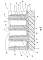
- FIG. 1 is a fragmentary perspective view of a microfuel cell according to the invention.
- FIG. 2 is a schematic cross-sectional view taken along Line 2-2 of FIG. 1.
- FIG. 3 is a schematic diagram of the microfuel cell of FIG. 1.
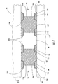
- FIG. 4 is a schematic cross-sectional view of another embodiment of a microfuel cell according to the invention.
- FIG. 5 is a schematic cross-sectional view of yet another embodiment of a microfuel cell according to the invention.
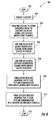
- FIG. 6 is a flow diagram of a method of making a microfuel cell according to the present invention.
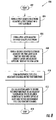
- FIG. 7 is a flow diagram of another method of making a microfuel cell according to the present invention.
- FIG. 8 is a flow diagram of yet another method of making a microfuel cell according to the present invention.
- the microfuel cell 30 illustratively includes a substrate 32 and a plurality of spaced-apart PEM dividers 34 extending outwardly from the substrate.
- the PEM dividers 34 define a plurality of anodic and cathodic microfluidic channels 36, 38 for carrying, respectively, an anodic reactant and a cathodic reactant.
- the microfuel cell 30 further illustratively includes an anodic catalyst/electrode 40 lining at least a portion of each of the anodic microfluidic channels 36 , and a cathodic catalyst/electrode 42 lining at least a portion of each of the cathodic microfluidic channels 38 .
- the plurality of anodic and cathodic microfluidic channels 36, 38 defined by the plurality of spaced-apart PEM dividers 34 are in an alternating relationship with one another.
- this provides particular advantages with respect to cooling the microfuel cell 30 and controlling the reactants within the microfluidic channels 36, 38 , other combinations and permutations are possible.
- anodic microfluidic channels could be arranged in pairs and alternate with pairs of cathodic microfluidic channels. Still other combinations and permutations are possible, as will be readily appreciated those skilled in the art.
- Each anodic catalyst/electrode 40 illustratively comprises an electrode layer 46 impregnated with an anodic catalyst.
- the anodic catalyst/electrode 40 may comprise a discrete catalyst layer underlying the porous electrode layer, the catalyst layer being thin enough to permit gas diffusion therethrough, as will be readily understood by those skilled in the art.
- Other types of anodic catalyst/electrodes may be alternately employed as will also be readily appreciated by those skilled in the art.
- a separate electrode 44 illustratively lies within each anodic microfluidic channel 36.
- the electrode may comprise, for example, aluminum or an aluminum alloy, doped or undoped polysilicon, gold, or tantalum.
- the catalytic effect provided by the anodic catalyst/electrode 40 may be enhanced, for example, by partially dispersing the impregnating catalyst or discrete catalyst layer in the neighboring surface of the respective PEM divider 34 , thereby increasing the reactive surface of the catalyst and reducing the travel path of ions (H + ) through the PEM divider during the energy generating reactions.
- the partial dispersion can be achieved, for example, by depositing a catalyst in granular form on the surface of the PEM divider 34 as will be appreciated by those skilled in the art.
- a thin metallic film may be deposited on the PEM divider 34 , the film, as already noted, being sufficiently thin to permit diffusion of a gaseous reactant, as will also be appreciated by those skilled in the art.
- An anodic diffusion layer 48 may optionally overlie each anodic catalyst/electrode 40 , as shown. Illustratively, the anodic diffusion layer 48 overlies the electrode layer 46 impregnated with an anodic catalyst.
- the anodic diffusion layer 48 provides distinct advantages, it alternately may be eliminated from the microfuel cell 30 in some applications. Conversely, in still other applications, more than one diffusion layer may be used. As will be readily understood by those skilled in the art, heaters may be added to a diffusion layer to prime the reactions associated with the anodic catalyst/electrode 40 .
- Each cathodic catalyst/electrode 42 likewise illustratively comprises an electrode layer 52 impregnated with a cathodic catalyst.
- the cathodic catalyst/electrode 42 alternately may comprise a discrete cathodic catalyst layer underlying a porous electrode layer and being thin enough to permit gas diffusion therethrough.
- the impregnating catalyst also may be partially dispersed in the neighboring surface of the respective PEM dividers 34 for enhanced catalytic effect.
- a separate electrode 50 illustratively lies within each cathodic microfluidic channel 38 , as well, and may comprise, for example, aluminum or an aluminum alloy, doped or undoped polysilicon, gold, or tantalum.
- a cathodic diffusion layer 54 illustratively overlies the cathodic catalyst/electrode 42 . Again, though the cathodic diffusion layer 54 provides distinct advantages, it may be eliminated in certain applications of the microfuel cell 30 .
- the microfuel cell 30 further comprises an anodic reactant manifold 56 that, as shown, is in fluid communication with the anodic microfluidic channels 36 .
- the microfuel cell 30 also illustratively includes a cathodic reactant manifold 58 that is in fluid communication with the microfluidic cathodic channels 38 .
- the anodic reactant manifold 56 and the cathodic reactant manifold 58 are able to cooperate with one another to cause the anodic and cathodic reactant to flow in opposite directions from one another as illustrated. This provides distinct cooling advantages relative to conventional microfuel cells.
- Conventional microfuel cells typically carry anodic reactants in side-by-side channels on one side of an electrolyte, with the anodic reactant carried in side-by-side channels on the opposite side of the electrolyte.
- a single anodic electrode typically is between the anodic channels and the electrolyte, and a single cathodic electrode is between the cathodic channels and electrolyte. Accordingly, heat is generated on the anodic side of the electrolyte where oxidation of a fuel such as hydrogen or methanol occurs, as well as on the cathodic side where oxygen is reduced.
- the present invention carries the reactants in opposite directions in alternating channels so that generated heat is more evenly distributed.
- the reactants may be carried in counterflow with respect to one another. Accordingly, the distal ends of the anodic channels 36 , where it is expected that the temperature of the anodic reactant will be greater, are between proximal ends of the cathodic channels 38 where the cathodic reactant is entering and, accordingly, expected to be relatively cooler. Conversely, the distal ends of the cathodic channels 38 are between proximal ends of the anodic channels where the anodic reactant is entering the anodic channels.
- This counterflow of the reactants thus provides advantageous cooling because the reactants entering at the proximal ends of their respective channels in a cooler state can be expected to cool the reactants that are farther inward along their respective channels and in a relatively warmer state.
- the cathodic channels also may be cooled by the water formed as a result of the combining of hydrogen and oxygen ions that are a by-product of the energy generating reaction.
- the PEM dividers 34 also provide a unique advantage in that they provide an enhanced catalyst surface-to-volume ratio. This, in turn, provides a better power-to-size trade-off in so far as there is more catalytic surface area for carrying out the reactions that generate electrical power without requiring a corresponding increase in the volume of the microfuel cell 30 . This makes the microfuel cell 30 particularly well suited for powering electronic devices needing a compact power source having a high power density.
- the microfluidic anodic reactant channels 36 and the microfluidic cathodic reactant channels 38 preferably have a height greater than a width thereof.
- the greater the height of a PEM divider 34 the greater is the surface area available to facilitate energy generating reactions thereon.
- the PEM dividers 34 may have a width of 20 microns and a height of 60 microns, with the space between any pair of PEM dividers being 5 microns.
- the microfuel cell 90 illustratively includes a substrate 92 .
- a plurality of spaced-apart PEM dividers 94 extends outwardly from the substrate 92 defining a plurality of anodic and cathodic microfluidic channels 96, 98 that carry respectively anodic and cathodic reactants.
- An anodic catalyst/electrode 100 lines at least a portion of each of the anodic microfluidic channels 96 while also extending beneath an adjacent portion of a respective PEM divider 94 .
- a cathodic catalyst/electrode 102 lines at least a portion of each cathodic microfluidic channel 98 and also extends beneath an adjacent portion of a respective PEM divider 94 .
- the plurality of anodic and cathodic microfluidic channels 96, 98 that are defined by the plurality of spaced-apart PEM dividers 94 illustratively alternate with one another.
- alternate arrangements of the anodic and cathodic channels relative to one another may be employed even though the illustrated arrangement provides particular advantages, for example, in terms of cooling the microfuel cell 90 .
- Each anodic catalyst/electrode 100 illustratively comprises an electrode layer 104 and an anodic catalyst layer 106 overlying the electrode layer.
- each cathodic catalyst/electrode 102 illustratively comprises an electrode layer 110 and a cathodic catalyst layer 112 overlying the electrode layer.
- Anodic and cathodic diffusion layers may optionally overly the anodic and cathodic catalyst layers, respectively.
- the microfuel cell 90 may include at least one additional substrate 114 from which a plurality of spaced-apart PEM dividers 116 outwardly extend, as shown.
- This second set of PEM dividers 116 may align with and connect to the PEM dividers extending outwardly from the other substrate 92 in defining the plurality of anodic and cathodic microfluidic channels 96, 98, as also shown.
- additional anodic catalyst/electrodes and cathodic catalyst/electrodes 118, 120 may optionally line at least a portion of the anodic and cathodic microfluidic channels 96, 98 , respectively.
- this microfuel cell 90 is that energy generating reactions occur at a point at which the anodic and cathodic catalyst electrodes are exposed to the anodic and cathodic reactants in their respective channels 96, 98 . Accordingly the reactants need not travel through an electrode layer to reach the PEM, thus allowing for an efficient energy generating reaction.
- the microfuel cell 150 illustratively includes a plurality of substrates 152A, 152B arranged in stacked relation, a first substrate 152A having first microfluidic fuel cell reactant channels 151 therein and opening upwardly to a first surface 153 thereof.
- a PEM layer 154 is illustratively adjacent the first surface 153 of the first substrate 152A and covers the first microfluidic fuel cell reactant channels 151 .
- an anodic catalyst/electrode 155 is adjacent one side of the PEM layer 154 and a cathodic catalyst/electrode 157 is adjacent an opposite side of the PEM layer.
- the anodic catalyst/electrode 155 illustratively comprises an electrode layer 156 impregnated with an anodic catalyst.
- the anodic catalyst/electrode 155 may instead comprise a discrete, thin catalyst layer adjacent the PEM layer 154 and a porous electrode layer adjacent the thin catalyst layer.
- a solid electrode 158 is adjacent the catalyst/electrode 155 .
- the cathodic catalyst/electrode 157 illustratively comprises an electrode layer 158 impregnated with a cathodic catalyst.
- the cathodic catalyst/electrode 157 may instead comprise a discrete thin cathodic catalyst layer adjacent the PEM layer 154 with a porous electrode layer overlying the thin cathodic catalyst layer.
- Another solid electrode 160 illustratively is adjacent the cathodic catalyst/electrode 157 .
- An adhesive layer 162 illustratively secures the first substrate 152A to an adjacent substrate 152B so that the first substrate and the adjacent substrate are in a spaced relation from one another to thereby define at least one second microfluidic fuel cell reactant channel 164 between the substrates.
- Each substrate 152A, 152B may itself be optionally formed from separate substrate portions, as shown. For example, channels may be etched into surfaces of each of two substrate portions 166A, 166B (e.g., formed from a silicon wafer). The respective channels may then be aligned and the respective substrate portions 166A, 166B adhered to one another with another adhesive layer 168 , as illustrated, thus forming the substrate 152A with first microfluidic fuel cell reactant channels 151 therein.
- a particular advantage of the microfuel cell 150 is that it provides increased surface area on which the energy generating reactions occur while also having a structure that lends itself to efficient manufacturing.
- the first microfluidic fuel cell reactant channels 151 are thus lined with anodic catalyst/electrodes 155 , while the cathodic catalyst/electrodes 157 are within the second microfluidic fuel cell reactant channel 164 between the respective substrates 152A, 152B . Accordingly, an anodic reactant is carried by the first microfluidic fuel cell reactant channels 151 , and a cathodic reactant is carried by the second microfluidic fuel cell reactant channel 164 between the respective substrates 152A, 152B .
- first microfluidic fuel cell reactant channels 151 instead may be lined with cathodic catalyst/electrodes, with the anodic catalyst/electrodes being within the second microfluidic fuel cell reactant channel 164 . Accordingly, a cathodic reactant may be carried by the first microfluidic fuel cell reactant channels 151 , and an anodic reactant may be carried by the second microfluidic fuel cell reactant channel 164 .
- the method may include providing a substrate 32 at Block 204.
- the method further illustratively includes forming a plurality of spaced-apart PEM dividers 34 to extend outwardly from the substrate 32 to thereby define a plurality of anodic and cathodic microfluidic channels 36, 38 for carrying respective anodic and cathodic reactants.
- the spaced-apart PEM dividers 34 illustratively define alternating anodic and cathodic microfluidic channels.
- the channels 36, 38 may be formed by depositing a layer of PEM material on the substrate 32 , and patterning and etching the layer using conventional semiconductor processing techniques as will be readily understood by those skill in the art.
- the method illustratively includes lining at least a portion of each anodic microfluidic channel 36 with an anodic catalyst/electrode 40 (Block 208 ).
- the method also illustratively includes lining at least a portion of each cathodic microfluidic channel 38 with a cathodic catalyst/electrode 42 (Block 210 ).
- the method further illustratively comprises at Block 212 forming an anodic reactant manifold 56 in fluid communication with the anodic microfluidic channels, and, at Block 214 , providing a cathodic reactant manifold 58 in fluid communication with the microfluidic cathodic channels.
- the anodic reactant manifold 56 and the cathodic reactant manifold 58 may be formed to cause respective anodic and cathodic reactant flows in opposite directions.
- the method illustratively concludes at Block 216 .
- Another method of making a microfuel cell comprises a method of making the microfuel cell 90 shown in FIG. 4.
- the method is now described with particular reference to the flow diagram 300 of FIG. 7.
- the method illustratively includes providing a first substrate 92 at Block 304 .
- a plurality of anodic catalyst/electrodes 100 are formed on the first substrate 92
- a plurality of cathodic catalyst/electrodes 102 are similarly formed on the first substrate.
- the method further includes forming a plurality of spaced-apart PEM dividers 94 to extend outwardly from the substrate 92 , each PEM divider also being formed to extend over an adjacent portion of a respective anodic catalyst/electrode 100 and over an adjacent portion of a respective cathodic catalyst/electrode 102 to thereby define a plurality of anodic and cathodic microfluidic channels 96, 98 for carrying respective anodic and cathodic reactants (Block 310 ).
- the method provides for lining at least a portion of each anodic microfluidic channel 96 with an anodic catalyst/electrode 100 so that each anodic catalyst/electrode extends beneath an adjacent portion of a respective PEM divider, and lining at least a portion of each cathodic microfluidic channel 98 with a cathodic catalyst/electrode 102 so that each cathodic catalyst/electrode extends beneath an adjacent portion of a respective PEM divider.
- the method may also include forming an anodic reactant manifold in fluid communication with the anodic microfluidic channels, and, at Block 314 , forming a cathodic reactant manifold in fluid communication with the cathodic microfluidic channels.
- a second substrate 114 from which a plurality of PEM dividers 116 extends may be stacked on the first substrate 92 (Block 316 ) such that respective PEM dividers of each substrate are aligned and adhered to one another.
- the method concludes at Block 318.
- the method upon starting (Block 402 ), illustratively includes at Block 404 forming a first electrode 158 and a first catalyst/electrode 155 adjacent a first surface 153 of a first substrate 152 A.
- a PEM layer 154 is formed adjacent the first catalyst electrode 155 (Block 406 ).
- a second electrode 160 and second catalyst/electrode 157 are formed adjacent the PEM layer at Block 408 so that the first electrode 158 and first catalyst/electrode 155 are on one side of the PEM layer 154, and the second electrode 160 and second catalyst/electrode 157 are on an opposite side of the PEM layer.
- microfluidic fuel cell channels are formed in the first substrate 152A .
- the PEM layer 154 , the first and second electrodes 158 , 160 , and the first and second catalyst/electrodes 155 , 157 may be formed on a front surface of one 166A of two substrate portions 166A , 166B , the back surface of which may then be etched away to form channels that open to the PEM layer 154 and catalyst/electrodes 155 , 157 .
- the channels may be etched before the PEM layer 154 , first and second electrodes 158 , 160 , and first and second catalyst/electrodes 155 , 157 are formed.
- Channels also may be etched in the other 166B of the two substrate portions 166A, 166B .
- the respective channels so formed in the substrate portions 166A, 166B may then be aligned and the substrates adhered to one another with an adhesive layer 168 to thus form a first substrate 152A. with first microfluidic fuel cell reactant channels 151 therein.
- the first catalyst/electrode 155 so formed comprises an anodic catalyst/electrode
- the second catalyst/electrode 157 comprises a cathodic catalyst/electrode
- the first catalyst/electrode may instead comprise a cathodic catalyst/electrode
- the second catalyst/electrode may comprise an anodic catalyst/electrode, as will be readily appreciated by those skilled in the art.
- an adhesive layer 162 is used to secure the first substrate 152A to a second substrate 152B in spaced relation therefrom to thereby define at least one second microfluidic fuel cell reactant channel 164 .
- the second substrate 152B may optionally include a PEM layer 170 , first and second electrodes 172, 174, and first and second catalyst/electrodes 176, 178. The method concludes at Block 414 .
Abstract
Description
As will be readily understood by one skilled in the art, these dimensions, as well as others, can be easily achieved by extending each of the plurality of spaced-apart
Vertical oxide pillars, for example, may be added for enhanced structural integrity as the height of the
Referring additionally now to FIG. 4, another embodiment of a
Claims (33)
- A microfuel cell comprising:a substrate;a plurality of spaced-apart proton exchange media (PEM) dividers extending outwardly from said substrate to define a plurality of anodic and cathodic microfluidic channels for carrying respective anodic and cathodic reactants;an anodic catalyst/electrode lining at least a portion of each of said anodic microfluidic channels; anda cathodic catalyst/electrode lining at least a portion of each of said cathodic microfluidic channels.
- A microfuel cell according to Claim 1 wherein each anodic and/or cathodic catalyst/electrode further extends beneath an adjacent portion of a respective PEM divider.
- A microfuel cell comprising:a substrate;a plurality of spaced-apart proton exchange media (PEM) dividers extending outwardly from said substrate to define a plurality of anodic and cathodic microfluidic channels for carrying respective anodic and cathodic reactants;an anodic catalyst/electrode lining at least a portion of each of said anodic microfluidic channels and extending beneath an adjacent portion of a respective PEM divider; anda cathodic catalyst/electrode lining at least a portion of each of said cathodic microfluidic channels and extending beneath an adjacent portion of a respective PEM divider.
- A microfuel cell according to any preceding Claim wherein the plurality of anodic and cathodic microfluidic channels defined by the plurality of spaced-apart PEM dividers are alternating anodic and cathodic microfluidic channels.
- A microfuel cell according to Claim 19 further comprising:an anodic reactant manifold in fluid communication with said anodic microfluidic channels; anda cathodic reactant manifold in fluid communication with said cathodic microfluidic channels.
- A microfuel cell according to Claim 5 wherein said anodic reactant manifold and said cathodic reactant manifold cause respective anodic and cathodic reactant flows in opposite directions.
- A microfuel cell according to Claim 5 or 6 wherein each anodic and/or cathodic reactant channel has a height greater than a width thereof.
- A microfuel cell according to any preceding Claim wherein each of said PEM dividers comprises an organic polymer.
- A mirofuel cell according to any preceding Claim wherein said substrate comprises silicon.
- A microfuel cell according to any preceding Claim wherein the anodic reactant comprises at least one of hydrogen (H2), methane (CH4), ethane (C2H6), propane (C3H8), butane (C4H10) , and methanol (CH3OH) .
- A microfuel cell according to any preceding Claim wherein the cathodic reactant comprises oxygen (O2).
- A microfuel cell comprising:a plurality of substrates arranged in stacked relation, a first substrate having first microfluidic fuel cell reactant channels therein and opening upwardly to a first surface thereof;a proton exchange media (PEM) layer adjacent the first surface of said first substrate and covering said microfluidic fuel cell reactant channels;an anodic catalyst/electrode adjacent one side of said PEM layer and a cathodic catalyst/electrode adjacent an opposite side of said PEM layer; andan adhesive layer securing said first substrate to an adjacent substrate in spaced relation therefrom and defining therebetween at least one second microfluidic fuel cell reactant channel.
- A microfuel cell according to any preceding Claim wherein said anodic catalyst/electrode comprises an electrode layer impregnated with an anodic catalyst.
- A microfuel cell according to any preceding Claim wherein said anodic catalyst/electrode comprises an electrode layer and an anodic catalyst layer adjacent said electrode layer.
- A microfuel cell according to any preceding Claim further comprising an anodic diffusion layer overlying each anodic catalyst/electrode.
- A microfuel cell according to any preceding Claim wherein said cathodic catalyst/electrode comprises an electrode layer impregnated with a cathodic catalyst.
- A microfuel cell according to any preceding Claim wherein said cathodic catalyst/electrode comprises an electrode layer and a cathodic catalyst layer adjacent said electrode layer.
- A microfuel cell according to any preceding Claim further comprising a cathodic diffusion layer overlying each cathodic catalyst/electrode.
- A microfuel cell according to any preceding Claim further comprising:a first reactant manifold in fluid communication with said first microfluidic fuel cell reactant channels for causing a first reactant fluid to flow therein; anda second reactant manifold in fluid communication with said at least one second microfluidic fuel cell reactant channel for causing a second reactant fluid to flow therein.
- A microfuel cell according to Claim 19 wherein said first reactant manifold and said second reactant manifold cause respective first and second reactant flows in opposite directions.
- A microfuel cell according to Claim 19 or 20 wherein said first reactant fluid comprises one of an anodic reactant fluid and a cathodic reactant fluid, and said second reactant fluid comprises the other of an anodic reactant fluid and a cathodic reactant fluid.
- A method of making a microfuel cell, the method comprising:forming a plurality of spaced-apart proton exchange media (PEM) dividers to extend outwardly from a substrate to thereby define a plurality of anodic and cathodic microfluidic channels for carrying respective anodic and cathodic reactants;lining at least a portion of each anodic microfluidic channel with an anodic catalyst/electrode; andlining at least a portion of each cathodic microfluidic channel with a cathodic catalyst/electrode.
- A method of making a microfuel cell, the method comprising:forming a plurality of anodic and cathodic catalyst/electrodes on a substrate; andforming a plurality of spaced-apart proton exchange media (PEM) dividers to extend outwardly from the substrate, each PEM divider being formed to also extend over an adjacent portion of a respective anodic catalyst/electrode and over an adjacent portion of a respective cathodic catalyst/electrode to thereby define a plurality of anodic and cathodic microfluidic channels for carrying respective anodic and cathodic reactants.
- A method according to Claim 22 or 23 wherein forming the plurality of spaced-apart PEM dividers further comprises forming the plurality of spaced-apart PEM dividers to extend from the substrate to define alternating anodic and cathodic microfluidic channels.
- A method of making a microfuel cell, the method comprising:forming a first electrode and a first catalyst/electrode adjacent a first surface of a first substrate;forming a proton exchange media (PEM) layer adjacent the first catalyst/electrode;forming a second electrode and a second catalyst/electrode adjacent the PEM layer such that the first electrode and first catalyst/electrode are adjacent one side of the PEM layer and the second electrode and second catalyst/electrode are adjacent an opposite side of the PEM layer;forming microfluidic fuel cell reactant channels in the first substrate so that the PEM layer covers the channels; andusing an adhesive layer for securing the first substrate to an adjacent substrate in spaced relation therefrom and defining therebetween at least one second microfluidic fuel cell reactant channel.
- A method according to Claim 25 wherein forming the first catalyst/electrode comprises forming one of an anodic and a cathodic catalyst/electrode and wherein forming the second catalyst/electrode comprises forming the other of an anodic and a cathodic catalyst/electrode.
- A method according to any of Claims 22 to 26 wherein each anodic catalyst/electrode comprises: an electrode layer impregnated with an anodic catalyst; or an electrode layer and an anodic catalyst layer adjacent the electrode layer.
- A method according to any of Claims 22 to 27 further comprising forming an anodic diffusion layer over each anodic catalyst/electrode.
- A method according to any of Claims 22 to 29 wherein each cathodic catalyst/electrode comprise: an electrode layer impregnated with a cathodic catalyst; or an electrode layer and a cathodic catalyst layer adjacent the electrode layer.
- A method according to any of Claims 22 to 29 further comprising forming a cathodic diffusion layer over each cathodic catalyst/electrode.
- A method according to any of Claims 22 to 30 wherein each anodic microfluidic reactant channel extends from the substrate to a height greater than a width of the anodic microfluidic reactant channels; and/or wherein each cathodic microfluidic reactant channel extends from the substrate to a height greater than a width of the cathodic microfluidic reactant channels.
- A method according to any of Claims 22 to 31 further comprising:forming a first manifold in fluid communication with the first or the anodic microfluidic channels; andforming a second manifold in fluid communication with the at least one second or cathodic microfluidic channel.
- A method according to Claim 32 wherein the first reactant manifold and the second reactant manifold are formed to cause respective first or anodic and second or cathodic reactant flows in opposite directions.
Applications Claiming Priority (2)
| Application Number | Priority Date | Filing Date | Title |
|---|---|---|---|
| US348519 | 1989-05-08 | ||
| US10/348,519 US7029781B2 (en) | 2003-01-21 | 2003-01-21 | Microfuel cell having anodic and cathodic microfluidic channels and related methods |
Publications (3)
| Publication Number | Publication Date |
|---|---|
| EP1450428A2 true EP1450428A2 (en) | 2004-08-25 |
| EP1450428A3 EP1450428A3 (en) | 2009-03-25 |
| EP1450428B1 EP1450428B1 (en) | 2011-03-16 |
Family
ID=32712569
Family Applications (1)
| Application Number | Title | Priority Date | Filing Date |
|---|---|---|---|
| EP04250284A Expired - Lifetime EP1450428B1 (en) | 2003-01-21 | 2004-01-20 | Microfuel cell comprising anodic and cathodic microfluidic channels and production methods thereof |
Country Status (4)
| Country | Link |
|---|---|
| US (1) | US7029781B2 (en) |
| EP (1) | EP1450428B1 (en) |
| JP (1) | JP4820058B2 (en) |
| DE (1) | DE602004031796D1 (en) |
Cited By (1)
| Publication number | Priority date | Publication date | Assignee | Title |
|---|---|---|---|---|
| US7547483B2 (en) | 2004-10-05 | 2009-06-16 | Stmicroelectronics, Inc. | Fuel cell device |
Families Citing this family (7)
| Publication number | Priority date | Publication date | Assignee | Title |
|---|---|---|---|---|
| JP4082276B2 (en) * | 2003-05-26 | 2008-04-30 | セイコーエプソン株式会社 | Imaging apparatus and driving method thereof |
| US8715882B2 (en) * | 2004-04-29 | 2014-05-06 | Lawrene Livermore National Security, LLC. | High power density fuel cell comprising an array of microchannels |
| ITVA20050034A1 (en) * | 2005-05-13 | 2006-11-14 | St Microelectronics Srl | FUEL CELLS MADE IN A SINGLE MONOCRYSTALLINE SILICON LAYER AND MANUFACTURING PROCESS |
| US20080061027A1 (en) * | 2006-09-12 | 2008-03-13 | Mangat Pawitter S | Method for forming a micro fuel cell |
| US20080292917A1 (en) * | 2007-05-23 | 2008-11-27 | Stmicroelectronics Sa | Portable electronic device with integrated fuel cell |
| US8557480B2 (en) * | 2009-08-26 | 2013-10-15 | Lawrence Livermore National Security, Llc | High power density fuel cell comprising an array of microchannels |
| EP3638404A4 (en) * | 2017-06-13 | 2021-03-10 | The Board of Trustees of the Leland Stanford Junior University | Electrochemical catalysts with enhanced catalytic activity |
Family Cites Families (26)
| Publication number | Priority date | Publication date | Assignee | Title |
|---|---|---|---|---|
| US5230849A (en) * | 1991-06-04 | 1993-07-27 | Michael S. Hsu | Electrochemical converter assembly and overlay methods of forming component structures |
| US5840438A (en) | 1995-08-25 | 1998-11-24 | Ballard Power Systems Inc. | Electrochemical fuel cell with an electrode substrate having an in-plane nonuniform structure for control of reactant and product transport |
| US5753385A (en) * | 1995-12-12 | 1998-05-19 | Regents Of The University Of California | Hybrid deposition of thin film solid oxide fuel cells and electrolyzers |
| JP3769958B2 (en) * | 1998-12-24 | 2006-04-26 | 三菱電機株式会社 | Fuel cell |
| US6638654B2 (en) * | 1999-02-01 | 2003-10-28 | The Regents Of The University Of California | MEMS-based thin-film fuel cells |
| JP2000277132A (en) * | 1999-03-25 | 2000-10-06 | Sanyo Electric Co Ltd | Fuel cell |
| JP2002544649A (en) * | 1999-05-06 | 2002-12-24 | サンディア コーポレーション | Fuel cells and membranes |
| US6924058B2 (en) | 1999-11-17 | 2005-08-02 | Leroy J. Ohlsen | Hydrodynamic transport and flow channel passageways associated with fuel cell electrode structures and fuel cell electrode stack assemblies |
| WO2001037357A2 (en) | 1999-11-17 | 2001-05-25 | Neah Power Systems, Inc. | Fuel cells having silicon substrates and/or sol-gel derived support structures |
| US6312846B1 (en) * | 1999-11-24 | 2001-11-06 | Integrated Fuel Cell Technologies, Inc. | Fuel cell and power chip technology |
| AU2270701A (en) * | 1999-12-17 | 2001-06-25 | International Fuel Cells, Llc | Fuel cell having a hydrophilic substrate layer |
| US6780533B2 (en) | 1999-12-17 | 2004-08-24 | Utc Fuel Cells, Llc | Fuel cell having interdigitated flow channels and water transport plates |
| US7427526B2 (en) * | 1999-12-20 | 2008-09-23 | The Penn State Research Foundation | Deposited thin films and their use in separation and sacrificial layer applications |
| US6415860B1 (en) * | 2000-02-09 | 2002-07-09 | Board Of Supervisors Of Louisiana State University And Agricultural And Mechanical College | Crossflow micro heat exchanger |
| US6689439B2 (en) * | 2000-03-08 | 2004-02-10 | Zbigniew S. Sobolewski | Micro-stud diffusion substrate for use in fuel cells |
| WO2001080286A2 (en) | 2000-04-17 | 2001-10-25 | The Penn State Research Foundation | Deposited thin films and their use in separation and sarcrificial layer applications |
| US7153602B2 (en) * | 2000-05-08 | 2006-12-26 | Honda Giken Kogyo Kabushiki Kaisha | Fuel cell assembly |
| US6818338B2 (en) * | 2000-05-08 | 2004-11-16 | Honda Giken Kogyo Kabushiki Kaisha | Fuel cell assembly |
| US6666909B1 (en) | 2000-06-06 | 2003-12-23 | Battelle Memorial Institute | Microsystem capillary separations |
| US6387559B1 (en) * | 2000-07-18 | 2002-05-14 | Motorola, Inc. | Direct methanol fuel cell system and method of fabrication |
| AU2001293157A1 (en) | 2000-10-06 | 2002-04-22 | International Fuel Cells, Llc | Porous carbon body for a fuel cell and method of manufacture |
| US6447945B1 (en) * | 2000-12-12 | 2002-09-10 | General Atomics | Portable electronic device powered by proton exchange membrane fuel cell |
| US6660423B2 (en) * | 2000-12-15 | 2003-12-09 | Motorola, Inc. | Direct methanol fuel cell including a water management system and method of fabrication |
| JP2002343379A (en) * | 2001-05-21 | 2002-11-29 | Aisin Seiki Co Ltd | Fuel cell, electrode for fuel cell and treating method of the same |
| US20020197520A1 (en) * | 2001-06-25 | 2002-12-26 | Usf Filtration & Separations Group., Inc | Micro fuel cell array |
| US6911275B2 (en) * | 2002-07-12 | 2005-06-28 | Utc Fuel Cells, Llc | High molecular weight direct antifreeze cooled fuel cell |
-
2003
- 2003-01-21 US US10/348,519 patent/US7029781B2/en active Active
-
2004
- 2004-01-20 EP EP04250284A patent/EP1450428B1/en not_active Expired - Lifetime
- 2004-01-20 DE DE602004031796T patent/DE602004031796D1/en not_active Expired - Lifetime
- 2004-01-21 JP JP2004013433A patent/JP4820058B2/en not_active Expired - Lifetime
Non-Patent Citations (1)
| Title |
|---|
| None |
Cited By (5)
| Publication number | Priority date | Publication date | Assignee | Title |
|---|---|---|---|---|
| US7547483B2 (en) | 2004-10-05 | 2009-06-16 | Stmicroelectronics, Inc. | Fuel cell device |
| US8178250B2 (en) | 2004-10-05 | 2012-05-15 | Stmicroelectronics, Inc. | Fuel cell device |
| US8202668B2 (en) | 2004-10-05 | 2012-06-19 | Stmicroelectronics, Inc. | Fuel cell device |
| US8202667B2 (en) | 2004-10-05 | 2012-06-19 | Stmicroelectronics, Inc. | Fuel cell device |
| US8367271B2 (en) | 2004-10-05 | 2013-02-05 | Stmicroelectronics, Inc. | Fuel cell device |
Also Published As
| Publication number | Publication date |
|---|---|
| US7029781B2 (en) | 2006-04-18 |
| DE602004031796D1 (en) | 2011-04-28 |
| EP1450428B1 (en) | 2011-03-16 |
| JP2004228089A (en) | 2004-08-12 |
| EP1450428A3 (en) | 2009-03-25 |
| JP4820058B2 (en) | 2011-11-24 |
| US20040142214A1 (en) | 2004-07-22 |
Similar Documents
| Publication | Publication Date | Title |
|---|---|---|
| JP4755574B2 (en) | Bipolar plates and fuel cells | |
| US6991868B2 (en) | Fuel cell assembly | |
| US8367270B2 (en) | Flow field plate arrangement for a fuel cell | |
| EP1722436B1 (en) | Polymer electrolyte fuel cell and bipolar separator for the same | |
| US7867666B2 (en) | Fuel cell with triangular buffers for reactant gas and coolant | |
| US20060172163A1 (en) | Fuel cell stack and fuel cell system having the same | |
| US6740444B2 (en) | PEM fuel cell with alternating ribbed anodes and cathodes | |
| KR100534677B1 (en) | Fuel cell | |
| US6531245B2 (en) | Fuel cell, separator for the same and method for distributing gas in fuel cell | |
| US20050266296A1 (en) | Stack having improved cooling structure and fuel cell system having the same | |
| KR100798451B1 (en) | Fuel cell separator and fuel cell stack and reactant gas control method thereof | |
| CN107732278A (en) | Fuel-cell stack assembly | |
| JP2009026727A (en) | Metal separator for fuel cell | |
| EP1450428B1 (en) | Microfuel cell comprising anodic and cathodic microfluidic channels and production methods thereof | |
| JP2005174648A (en) | Fuel cell | |
| JP2002141084A (en) | Fuel cell | |
| US7951508B2 (en) | Fuel cell | |
| US20050282051A1 (en) | Integrated honeycomb solid electrolyte fuel cells | |
| US20060063045A1 (en) | Fuel cell stack and fuel cell system having the same | |
| US7745062B2 (en) | Fuel cell having coolant inlet and outlet buffers on a first and second side | |
| EP0967675B1 (en) | Fuel cell and method for distributing gas in fuel cell | |
| JP4438569B2 (en) | Reactor | |
| US20220246949A1 (en) | Fuel cell stack comprising variable bipolar plates | |
| JP2004146145A (en) | Solid polyelectrolyte fuel cell | |
| US11936075B2 (en) | Separator for solid oxide fuel cell (SOFC) stack capable of minimizing system volume and usage of sealant |
Legal Events
| Date | Code | Title | Description |
|---|---|---|---|
| PUAI | Public reference made under article 153(3) epc to a published international application that has entered the european phase |
Free format text: ORIGINAL CODE: 0009012 |
|
| AK | Designated contracting states |
Kind code of ref document: A2 Designated state(s): AT BE BG CH CY CZ DE DK EE ES FI FR GB GR HU IE IT LI LU MC NL PT RO SE SI SK TR |
|
| AX | Request for extension of the european patent |
Extension state: AL LT LV MK |
|
| RTI1 | Title (correction) |
Free format text: MICROFUEL CELL COMPRISING ANODIC AND CATHODIC MICROFLUIDIC CHANNELS AND PRODUCTION METHODS THEREOF |
|
| RAP1 | Party data changed (applicant data changed or rights of an application transferred) |
Owner name: STMICROELECTRONICS, INC. Owner name: STMICROELECTRONICS S.R.L. |
|
| PUAL | Search report despatched |
Free format text: ORIGINAL CODE: 0009013 |
|
| AK | Designated contracting states |
Kind code of ref document: A3 Designated state(s): AT BE BG CH CY CZ DE DK EE ES FI FR GB GR HU IE IT LI LU MC NL PT RO SE SI SK TR |
|
| AX | Request for extension of the european patent |
Extension state: AL LT LV MK |
|
| 17P | Request for examination filed |
Effective date: 20090916 |
|
| 17Q | First examination report despatched |
Effective date: 20091008 |
|
| AKX | Designation fees paid |
Designated state(s): DE FR GB IT |
|
| R17C | First examination report despatched (corrected) |
Effective date: 20091030 |
|
| RAP1 | Party data changed (applicant data changed or rights of an application transferred) |
Owner name: STMICROELECTRONICS SRL Owner name: STMICROELECTRONICS, INC. |
|
| GRAP | Despatch of communication of intention to grant a patent |
Free format text: ORIGINAL CODE: EPIDOSNIGR1 |
|
| GRAS | Grant fee paid |
Free format text: ORIGINAL CODE: EPIDOSNIGR3 |
|
| GRAA | (expected) grant |
Free format text: ORIGINAL CODE: 0009210 |
|
| AK | Designated contracting states |
Kind code of ref document: B1 Designated state(s): DE FR GB IT |
|
| REG | Reference to a national code |
Ref country code: GB Ref legal event code: FG4D |
|
| REF | Corresponds to: |
Ref document number: 602004031796 Country of ref document: DE Date of ref document: 20110428 Kind code of ref document: P |
|
| REG | Reference to a national code |
Ref country code: DE Ref legal event code: R096 Ref document number: 602004031796 Country of ref document: DE Effective date: 20110428 |
|
| PLBE | No opposition filed within time limit |
Free format text: ORIGINAL CODE: 0009261 |
|
| STAA | Information on the status of an ep patent application or granted ep patent |
Free format text: STATUS: NO OPPOSITION FILED WITHIN TIME LIMIT |
|
| 26N | No opposition filed |
Effective date: 20111219 |
|
| REG | Reference to a national code |
Ref country code: DE Ref legal event code: R097 Ref document number: 602004031796 Country of ref document: DE Effective date: 20111219 |
|
| PG25 | Lapsed in a contracting state [announced via postgrant information from national office to epo] |
Ref country code: IT Free format text: LAPSE BECAUSE OF FAILURE TO SUBMIT A TRANSLATION OF THE DESCRIPTION OR TO PAY THE FEE WITHIN THE PRESCRIBED TIME-LIMIT Effective date: 20110316 |
|
| PG25 | Lapsed in a contracting state [announced via postgrant information from national office to epo] |
Ref country code: DE Free format text: LAPSE BECAUSE OF NON-PAYMENT OF DUE FEES Effective date: 20120801 |
|
| REG | Reference to a national code |
Ref country code: DE Ref legal event code: R119 Ref document number: 602004031796 Country of ref document: DE Effective date: 20120801 |
|
| REG | Reference to a national code |
Ref country code: FR Ref legal event code: PLFP Year of fee payment: 13 |
|
| REG | Reference to a national code |
Ref country code: FR Ref legal event code: PLFP Year of fee payment: 14 |
|
| REG | Reference to a national code |
Ref country code: FR Ref legal event code: PLFP Year of fee payment: 15 |
|
| PGFP | Annual fee paid to national office [announced via postgrant information from national office to epo] |
Ref country code: GB Payment date: 20221221 Year of fee payment: 20 Ref country code: FR Payment date: 20221220 Year of fee payment: 20 |
|
| REG | Reference to a national code |
Ref country code: GB Ref legal event code: PE20 Expiry date: 20240119 |