EP1450112A1 - Humidity conditioning element, humidity conditioner, and humidification unit of air conditioner - Google Patents
Humidity conditioning element, humidity conditioner, and humidification unit of air conditioner Download PDFInfo
- Publication number
- EP1450112A1 EP1450112A1 EP02772985A EP02772985A EP1450112A1 EP 1450112 A1 EP1450112 A1 EP 1450112A1 EP 02772985 A EP02772985 A EP 02772985A EP 02772985 A EP02772985 A EP 02772985A EP 1450112 A1 EP1450112 A1 EP 1450112A1
- Authority
- EP
- European Patent Office
- Prior art keywords
- air
- regulating element
- humidifying
- humidity regulating
- catalyst
- Prior art date
- Legal status (The legal status is an assumption and is not a legal conclusion. Google has not performed a legal analysis and makes no representation as to the accuracy of the status listed.)
- Granted
Links
Images




Classifications
-
- F—MECHANICAL ENGINEERING; LIGHTING; HEATING; WEAPONS; BLASTING
- F24—HEATING; RANGES; VENTILATING
- F24F—AIR-CONDITIONING; AIR-HUMIDIFICATION; VENTILATION; USE OF AIR CURRENTS FOR SCREENING
- F24F6/00—Air-humidification, e.g. cooling by humidification
-
- A—HUMAN NECESSITIES
- A61—MEDICAL OR VETERINARY SCIENCE; HYGIENE
- A61L—METHODS OR APPARATUS FOR STERILISING MATERIALS OR OBJECTS IN GENERAL; DISINFECTION, STERILISATION OR DEODORISATION OF AIR; CHEMICAL ASPECTS OF BANDAGES, DRESSINGS, ABSORBENT PADS OR SURGICAL ARTICLES; MATERIALS FOR BANDAGES, DRESSINGS, ABSORBENT PADS OR SURGICAL ARTICLES
- A61L9/00—Disinfection, sterilisation or deodorisation of air
- A61L9/01—Deodorant compositions
- A61L9/014—Deodorant compositions containing sorbent material, e.g. activated carbon
-
- A—HUMAN NECESSITIES
- A61—MEDICAL OR VETERINARY SCIENCE; HYGIENE
- A61L—METHODS OR APPARATUS FOR STERILISING MATERIALS OR OBJECTS IN GENERAL; DISINFECTION, STERILISATION OR DEODORISATION OF AIR; CHEMICAL ASPECTS OF BANDAGES, DRESSINGS, ABSORBENT PADS OR SURGICAL ARTICLES; MATERIALS FOR BANDAGES, DRESSINGS, ABSORBENT PADS OR SURGICAL ARTICLES
- A61L9/00—Disinfection, sterilisation or deodorisation of air
- A61L9/16—Disinfection, sterilisation or deodorisation of air using physical phenomena
-
- B—PERFORMING OPERATIONS; TRANSPORTING
- B01—PHYSICAL OR CHEMICAL PROCESSES OR APPARATUS IN GENERAL
- B01D—SEPARATION
- B01D53/00—Separation of gases or vapours; Recovering vapours of volatile solvents from gases; Chemical or biological purification of waste gases, e.g. engine exhaust gases, smoke, fumes, flue gases, aerosols
- B01D53/02—Separation of gases or vapours; Recovering vapours of volatile solvents from gases; Chemical or biological purification of waste gases, e.g. engine exhaust gases, smoke, fumes, flue gases, aerosols by adsorption, e.g. preparative gas chromatography
- B01D53/06—Separation of gases or vapours; Recovering vapours of volatile solvents from gases; Chemical or biological purification of waste gases, e.g. engine exhaust gases, smoke, fumes, flue gases, aerosols by adsorption, e.g. preparative gas chromatography with moving adsorbents, e.g. rotating beds
-
- B—PERFORMING OPERATIONS; TRANSPORTING
- B01—PHYSICAL OR CHEMICAL PROCESSES OR APPARATUS IN GENERAL
- B01D—SEPARATION
- B01D53/00—Separation of gases or vapours; Recovering vapours of volatile solvents from gases; Chemical or biological purification of waste gases, e.g. engine exhaust gases, smoke, fumes, flue gases, aerosols
- B01D53/26—Drying gases or vapours
- B01D53/261—Drying gases or vapours by adsorption
-
- B—PERFORMING OPERATIONS; TRANSPORTING
- B01—PHYSICAL OR CHEMICAL PROCESSES OR APPARATUS IN GENERAL
- B01J—CHEMICAL OR PHYSICAL PROCESSES, e.g. CATALYSIS OR COLLOID CHEMISTRY; THEIR RELEVANT APPARATUS
- B01J20/00—Solid sorbent compositions or filter aid compositions; Sorbents for chromatography; Processes for preparing, regenerating or reactivating thereof
- B01J20/02—Solid sorbent compositions or filter aid compositions; Sorbents for chromatography; Processes for preparing, regenerating or reactivating thereof comprising inorganic material
- B01J20/10—Solid sorbent compositions or filter aid compositions; Sorbents for chromatography; Processes for preparing, regenerating or reactivating thereof comprising inorganic material comprising silica or silicate
- B01J20/16—Alumino-silicates
- B01J20/18—Synthetic zeolitic molecular sieves
-
- F—MECHANICAL ENGINEERING; LIGHTING; HEATING; WEAPONS; BLASTING
- F24—HEATING; RANGES; VENTILATING
- F24F—AIR-CONDITIONING; AIR-HUMIDIFICATION; VENTILATION; USE OF AIR CURRENTS FOR SCREENING
- F24F1/00—Room units for air-conditioning, e.g. separate or self-contained units or units receiving primary air from a central station
- F24F1/0003—Room units for air-conditioning, e.g. separate or self-contained units or units receiving primary air from a central station characterised by a split arrangement, wherein parts of the air-conditioning system, e.g. evaporator and condenser, are in separately located units
-
- F—MECHANICAL ENGINEERING; LIGHTING; HEATING; WEAPONS; BLASTING
- F24—HEATING; RANGES; VENTILATING
- F24F—AIR-CONDITIONING; AIR-HUMIDIFICATION; VENTILATION; USE OF AIR CURRENTS FOR SCREENING
- F24F1/00—Room units for air-conditioning, e.g. separate or self-contained units or units receiving primary air from a central station
- F24F1/06—Separate outdoor units, e.g. outdoor unit to be linked to a separate room comprising a compressor and a heat exchanger
-
- F—MECHANICAL ENGINEERING; LIGHTING; HEATING; WEAPONS; BLASTING
- F24—HEATING; RANGES; VENTILATING
- F24F—AIR-CONDITIONING; AIR-HUMIDIFICATION; VENTILATION; USE OF AIR CURRENTS FOR SCREENING
- F24F1/00—Room units for air-conditioning, e.g. separate or self-contained units or units receiving primary air from a central station
- F24F1/06—Separate outdoor units, e.g. outdoor unit to be linked to a separate room comprising a compressor and a heat exchanger
- F24F1/46—Component arrangements in separate outdoor units
-
- F—MECHANICAL ENGINEERING; LIGHTING; HEATING; WEAPONS; BLASTING
- F24—HEATING; RANGES; VENTILATING
- F24F—AIR-CONDITIONING; AIR-HUMIDIFICATION; VENTILATION; USE OF AIR CURRENTS FOR SCREENING
- F24F3/00—Air-conditioning systems in which conditioned primary air is supplied from one or more central stations to distributing units in the rooms or spaces where it may receive secondary treatment; Apparatus specially designed for such systems
- F24F3/12—Air-conditioning systems in which conditioned primary air is supplied from one or more central stations to distributing units in the rooms or spaces where it may receive secondary treatment; Apparatus specially designed for such systems characterised by the treatment of the air otherwise than by heating and cooling
- F24F3/14—Air-conditioning systems in which conditioned primary air is supplied from one or more central stations to distributing units in the rooms or spaces where it may receive secondary treatment; Apparatus specially designed for such systems characterised by the treatment of the air otherwise than by heating and cooling by humidification; by dehumidification
- F24F3/1411—Air-conditioning systems in which conditioned primary air is supplied from one or more central stations to distributing units in the rooms or spaces where it may receive secondary treatment; Apparatus specially designed for such systems characterised by the treatment of the air otherwise than by heating and cooling by humidification; by dehumidification by absorbing or adsorbing water, e.g. using an hygroscopic desiccant
- F24F3/1423—Air-conditioning systems in which conditioned primary air is supplied from one or more central stations to distributing units in the rooms or spaces where it may receive secondary treatment; Apparatus specially designed for such systems characterised by the treatment of the air otherwise than by heating and cooling by humidification; by dehumidification by absorbing or adsorbing water, e.g. using an hygroscopic desiccant with a moving bed of solid desiccants, e.g. a rotary wheel supporting solid desiccants
-
- F—MECHANICAL ENGINEERING; LIGHTING; HEATING; WEAPONS; BLASTING
- F24—HEATING; RANGES; VENTILATING
- F24F—AIR-CONDITIONING; AIR-HUMIDIFICATION; VENTILATION; USE OF AIR CURRENTS FOR SCREENING
- F24F8/00—Treatment, e.g. purification, of air supplied to human living or working spaces otherwise than by heating, cooling, humidifying or drying
- F24F8/10—Treatment, e.g. purification, of air supplied to human living or working spaces otherwise than by heating, cooling, humidifying or drying by separation, e.g. by filtering
- F24F8/192—Treatment, e.g. purification, of air supplied to human living or working spaces otherwise than by heating, cooling, humidifying or drying by separation, e.g. by filtering by electrical means, e.g. by applying electrostatic fields or high voltages
-
- F—MECHANICAL ENGINEERING; LIGHTING; HEATING; WEAPONS; BLASTING
- F24—HEATING; RANGES; VENTILATING
- F24F—AIR-CONDITIONING; AIR-HUMIDIFICATION; VENTILATION; USE OF AIR CURRENTS FOR SCREENING
- F24F8/00—Treatment, e.g. purification, of air supplied to human living or working spaces otherwise than by heating, cooling, humidifying or drying
- F24F8/20—Treatment, e.g. purification, of air supplied to human living or working spaces otherwise than by heating, cooling, humidifying or drying by sterilisation
- F24F8/22—Treatment, e.g. purification, of air supplied to human living or working spaces otherwise than by heating, cooling, humidifying or drying by sterilisation using UV light
-
- B—PERFORMING OPERATIONS; TRANSPORTING
- B01—PHYSICAL OR CHEMICAL PROCESSES OR APPARATUS IN GENERAL
- B01D—SEPARATION
- B01D2253/00—Adsorbents used in seperation treatment of gases and vapours
- B01D2253/10—Inorganic adsorbents
- B01D2253/106—Silica or silicates
- B01D2253/108—Zeolites
-
- B—PERFORMING OPERATIONS; TRANSPORTING
- B01—PHYSICAL OR CHEMICAL PROCESSES OR APPARATUS IN GENERAL
- B01D—SEPARATION
- B01D2255/00—Catalysts
- B01D2255/80—Type of catalytic reaction
- B01D2255/802—Photocatalytic
-
- B—PERFORMING OPERATIONS; TRANSPORTING
- B01—PHYSICAL OR CHEMICAL PROCESSES OR APPARATUS IN GENERAL
- B01D—SEPARATION
- B01D2257/00—Components to be removed
- B01D2257/30—Sulfur compounds
- B01D2257/306—Organic sulfur compounds, e.g. mercaptans
-
- B—PERFORMING OPERATIONS; TRANSPORTING
- B01—PHYSICAL OR CHEMICAL PROCESSES OR APPARATUS IN GENERAL
- B01D—SEPARATION
- B01D2257/00—Components to be removed
- B01D2257/80—Water
-
- B—PERFORMING OPERATIONS; TRANSPORTING
- B01—PHYSICAL OR CHEMICAL PROCESSES OR APPARATUS IN GENERAL
- B01D—SEPARATION
- B01D2257/00—Components to be removed
- B01D2257/90—Odorous compounds not provided for in groups B01D2257/00 - B01D2257/708
-
- B—PERFORMING OPERATIONS; TRANSPORTING
- B01—PHYSICAL OR CHEMICAL PROCESSES OR APPARATUS IN GENERAL
- B01D—SEPARATION
- B01D2259/00—Type of treatment
- B01D2259/40—Further details for adsorption processes and devices
- B01D2259/40083—Regeneration of adsorbents in processes other than pressure or temperature swing adsorption
- B01D2259/40088—Regeneration of adsorbents in processes other than pressure or temperature swing adsorption by heating
-
- F—MECHANICAL ENGINEERING; LIGHTING; HEATING; WEAPONS; BLASTING
- F24—HEATING; RANGES; VENTILATING
- F24F—AIR-CONDITIONING; AIR-HUMIDIFICATION; VENTILATION; USE OF AIR CURRENTS FOR SCREENING
- F24F2203/00—Devices or apparatus used for air treatment
- F24F2203/10—Rotary wheel
- F24F2203/1012—Details of the casing or cover
-
- F—MECHANICAL ENGINEERING; LIGHTING; HEATING; WEAPONS; BLASTING
- F24—HEATING; RANGES; VENTILATING
- F24F—AIR-CONDITIONING; AIR-HUMIDIFICATION; VENTILATION; USE OF AIR CURRENTS FOR SCREENING
- F24F2203/00—Devices or apparatus used for air treatment
- F24F2203/10—Rotary wheel
- F24F2203/1016—Rotary wheel combined with another type of cooling principle, e.g. compression cycle
-
- F—MECHANICAL ENGINEERING; LIGHTING; HEATING; WEAPONS; BLASTING
- F24—HEATING; RANGES; VENTILATING
- F24F—AIR-CONDITIONING; AIR-HUMIDIFICATION; VENTILATION; USE OF AIR CURRENTS FOR SCREENING
- F24F2203/00—Devices or apparatus used for air treatment
- F24F2203/10—Rotary wheel
- F24F2203/1032—Desiccant wheel
- F24F2203/1036—Details
-
- F—MECHANICAL ENGINEERING; LIGHTING; HEATING; WEAPONS; BLASTING
- F24—HEATING; RANGES; VENTILATING
- F24F—AIR-CONDITIONING; AIR-HUMIDIFICATION; VENTILATION; USE OF AIR CURRENTS FOR SCREENING
- F24F2203/00—Devices or apparatus used for air treatment
- F24F2203/10—Rotary wheel
- F24F2203/1056—Rotary wheel comprising a reheater
-
- F—MECHANICAL ENGINEERING; LIGHTING; HEATING; WEAPONS; BLASTING
- F24—HEATING; RANGES; VENTILATING
- F24F—AIR-CONDITIONING; AIR-HUMIDIFICATION; VENTILATION; USE OF AIR CURRENTS FOR SCREENING
- F24F2203/00—Devices or apparatus used for air treatment
- F24F2203/10—Rotary wheel
- F24F2203/1068—Rotary wheel comprising one rotor
-
- F—MECHANICAL ENGINEERING; LIGHTING; HEATING; WEAPONS; BLASTING
- F24—HEATING; RANGES; VENTILATING
- F24F—AIR-CONDITIONING; AIR-HUMIDIFICATION; VENTILATION; USE OF AIR CURRENTS FOR SCREENING
- F24F2203/00—Devices or apparatus used for air treatment
- F24F2203/10—Rotary wheel
- F24F2203/1084—Rotary wheel comprising two flow rotor segments
-
- Y—GENERAL TAGGING OF NEW TECHNOLOGICAL DEVELOPMENTS; GENERAL TAGGING OF CROSS-SECTIONAL TECHNOLOGIES SPANNING OVER SEVERAL SECTIONS OF THE IPC; TECHNICAL SUBJECTS COVERED BY FORMER USPC CROSS-REFERENCE ART COLLECTIONS [XRACs] AND DIGESTS
- Y02—TECHNOLOGIES OR APPLICATIONS FOR MITIGATION OR ADAPTATION AGAINST CLIMATE CHANGE
- Y02A—TECHNOLOGIES FOR ADAPTATION TO CLIMATE CHANGE
- Y02A50/00—TECHNOLOGIES FOR ADAPTATION TO CLIMATE CHANGE in human health protection, e.g. against extreme weather
- Y02A50/20—Air quality improvement or preservation, e.g. vehicle emission control or emission reduction by using catalytic converters
Definitions
- the present invention relates to a humidity regulating element, a humidity regulator, and a humidifying unit of an air conditioner. More particularly, the present invention relates to a humidity regulating element that includes a moisture adsorbing and desorbing material that adsorbs and desorbs moisture; and a humidifying unit of a humidity regulator or an air conditioner, provided with the humidity regulating element.
- Air conditioners have recently appeared on the market provided with a humidifying unit that takes in moisture from the outdoor air and transfers moisture to an indoor space.
- This humidifying unit has a structure like, for example, the one disclosed in Japanese Patent Application Kokai No. 2001-41511.
- a humidifying rotor made of, for example, zeolite, is used to humidify air delivered to an indoor space. Specifically, the moisture in the air is adsorbed on the humidifying rotor, and that moisture is then desorbed from the humidifying rotor using a heater. By adding that desorbed moisture to the air delivered to the indoor space, the air delivered to the indoor space is thereby humidified.
- humidified air can be supplied to the indoor space by an air conditioner provided with a humidifying unit, the indoor relative humidity can be maintained at a comfortable level even, for example, in the winter when the air is dry.
- the abovementioned humidifying unit is provided with a function that supplies air taken in from an outdoor space to the indoor space, it is also possible to perform ventilation by using the function of supplying outdoor air to the indoor space.
- the humidifying unit takes in air from the outdoor space, humidifies that air (or does not humidify that air), and then supplies the air to the indoor space.
- the humidifying unit is also provided with a ventilation function, as described above. Because the outdoor air is generally cleaner than the indoor air, it can be said that the humidifying unit provides greater value than an air conditioner because it delivers outdoor air to the indoor space.
- One object of the present invention is to provide a humidity regulating element that can decrease the amount of pollutants in the air while controlling an increase in the size of the apparatus that has the humidity regulator function, such as the humidifying unit; and to provide a humidifying unit of a humidity regulator or an air conditioner that increases the effectiveness of that humidity regulating element.
- the humidity regulating element as recited in Claim 1 is an element, monolithically comprising: a moisture adsorbing and desorbing material for adsorbing and desorbing moisture from and to the air; and a catalyst for decreasing polluting components in the air.
- the single element includes a moisture adsorbing and desorbing material that can regulate the humidity of the air by adsorbing and desorbing moisture, and a catalyst for decreasing the polluting components in the air.
- a humidity regulating element that monolithically comprises a moisture adsorbing and desorbing material and a catalyst, the provision of, for example, a separate filter is no longer needed, and the amount of polluting components in the air can be decreased by passing the air through the humidity regulating element, while controlling an increase in the size of the apparatus, such as a dehumidifier, a humidifier, a dehumidifier/humidifier, or an air conditioner.
- zeolite silica gel, or alumina
- catalysts such as a noble metal catalyst, an oxide catalyst, or a photocatalyst
- a technique is used that impregnates, for example, a ceramic with zeolite.
- a technique that impregnates a base metal with the catalyst it is also acceptable to employ a technique that impregnates a base metal with the catalyst, and it is also acceptable to use a technique that coats the catalyst on at least one portion of the surface of a base metal.
- the humidity regulating element as recited in Claim 2 is the humidity regulating element as recited in Claim 1, wherein the catalyst is a deodorizing catalyst that decomposes an odor component in the air into an odorless component.
- the catalyst in the humidity regulating element decomposes the odor component in the air into an odorless component, most of the odor component is eliminated from the air that passes through this element. Accordingly, even if using an apparatus that draws in indoor air, once again regulates the humidity of that air, and then supplies that air to the indoor space; or even if using an apparatus that takes in outdoor air, and supplies that air to the indoor space; then the odor component is decreased by passing the air through the element of the present claim, thereby no longer causing discomfort to the user of the apparatus.
- odor components include, for example, methyl sulfide, ammonia, trimethylamine, and acetaldehyde (included in tobacco smoke).
- the humidity regulating element as recited in Claim 3 is the humidity regulating element as recited in Claim 1 or Claim 2, wherein the catalyst changes a deleterious component in the air into an innocuous component.
- the catalyst in the humidity regulating element changes deleterious components in the air into innocuous components, most of the deleterious components are eliminated from the air that passes through this element. Accordingly, even if using an apparatus that takes in the indoor air, once again regulates the humidity of that air, and then supplies that air to the indoor space; and even if using an apparatus that takes in outdoor air and supplies that air to the indoor space; then the deleterious components are decreased by passing the air through the element of the present claim, and thereby the harm to the user of the apparatus from the deleterious component is decreased.
- deleterious components include, for example, dioxin, formaldehyde, as well as NOx, SOx, CO, and HC, which are included in the exhaust gas of automobiles and the like.
- the humidity regulating element as recited in Claim 4 is the humidity regulating element as recited in any one claim of Claim 1 through Claim 3, wherein at least a portion of the catalyst is a photocatalyst.
- a representative photocatalyst is titanium oxide. Further, there is virtually no decline in the functioning of the titanium oxide as a catalyst, and its effectiveness is maintained semipermanently.
- the humidity regulating element as recited in Claim 5 is the humidity regulating element as recited in any one claim of Claim 1 through Claim 4, wherein the moisture adsorbing and desorbing material is present approximately uniformly over the entirety of the humidity regulating element, and the catalyst is present in a portion of the humidity regulating element.
- the amount of moisture that can be adsorbed and desorbed with respect to the size of the element is large because the moisture adsorbing and desorbing material is present in an approximately uniform manner over the entirety of the element.
- the humidity regulator as recited in Claim 6 comprises the humidity regulating element as recited in Claim 4, a lamp, and a fan.
- the lamp irradiates the humidity regulating element with light having a wavelength in a predetermined range.
- the fan passes air through the humidity regulating element.
- the humidity regulator of the present claim is provided with a lamp that irradiates the humidity regulating element, which includes the photocatalyst, with prescribed light. Consequently, it is possible to amply produce the one function of the humidity regulating element, i.e., to decrease the amount of polluting components in the air, even if the humidity regulator is arranged at a location, e.g., where sunlight does not easily impinge on the humidity regulating element.
- the humidity regulator is, for example, an air conditioner having a humidifying function, an apparatus specialized for dehumidification, and an apparatus specialized for humidification.
- the humidity regulator as recited in Claim 7 comprises the humidity regulating element as recited in Claim 4, and a casing that covers the humidity regulating element. Therein, an opening is formed in the casing. Light having a wavelength in a predetermined range impinges directly or after reflection upon the humidity regulating element via this opening.
- the prescribed light e.g., ultraviolet light included in sun rays, fluorescent lamps, and the like
- impinging on a photocatalyst generates active oxygen, which decomposes organic substances, and the like. Accordingly, if the amount of light impinging on the photocatalyst is insufficient, then the catalyst no longer functions sufficiently. Therefore, in the humidity regulator of the present claim, an opening is formed in the casing that covers the humidity regulating element, and that opening is such that prescribed light impinges on the humidity regulating element via the opening.
- the humidity regulating element is arranged at a location where sunlight does not easily impinge without an opening, e.g., even if the humidity regulating element is entirely sealed by a casing, it is possible to sufficiently produce one function of the humidity regulating element, i.e., to decrease the amount of polluting components in the air.
- the light that impinges on the humidity regulating element via the opening in the casing impinges directly on the humidity regulating element from the light source, and it is also acceptable if it impinges on the humidity regulating element via a reflection. Accordingly, even if the casing is arranged in the shade, then it is possible to sufficiently produce one function of the humidity regulating element, i.e., to decrease the amount of the polluting components in the air, if constituted so that an opening is provided in the casing, and the reflected light impinges on the humidity regulating element.
- the humidity regulator is, e.g., an air conditioner having a humidifying function, an apparatus specialized for dehumidification, or an apparatus specialized for humidification.
- the humidifying unit of an air conditioner as recited in Claim 8 is a humidifying unit for adding humidified air to the regulated air supplied to an indoor space, comprising the humidity regulating element as recited in any one claim of Claim 1 through Claim 5; a heater; and a fan.
- the heater heats the humidity regulating element.
- the fan passes air through the humidity regulating element.
- the humidity regulating element which includes a catalyst, has a function that decreases the amount of the polluting component in the air, that function can be produced effectively if the humidity regulating element is heated to a high temperature by a heater.
- the humidifying unit of the air conditioner as recited in Claim 9 is the humidifying unit as recited in Claim 8, wherein most of the catalyst is included in a portion on the heater side of the humidity regulating element.
- catalysts wherein the value that indicates the effectiveness in decreasing the polluting components (e.g., the rate of decomposition of the polluting components) increases at high temperatures.
- the catalyst is included in the humidity regulating element, it is preferable to heat the catalyst.
- the humidifying unit of the present claim is constituted so that most of the catalyst in the humidity regulating element is included in a portion near the heater that heats the humidity regulating element (heater side portion). Thereby, the effectiveness of decreasing the polluting components by the catalyst can be increased.
- the humidifying unit of the air conditioner as recited in Claim 10 is the humidifying unit as recited in Claim 8 or Claim 9, and is a unit that takes in air from the outdoor space, and supplies that air to the indoor space.
- the air conditioner can perform a humidifying operation, wherein humidified air from the humidifying unit is supplied to the indoor space, and an air supplying operation, wherein non-humidified air from the humidifying unit is supplied to the indoor space.
- the heater executes a first heating control mode for desorbing moisture from the humidity regulating element when in the humidifying operation, and executes a second heating control mode for promoting the function of the catalyst of the humidity regulating element when in the air supplying operation.
- the heater is controlled so that the humidity regulating function of the humidity regulating element is sufficiently produced when in the humidifying operation (first heating control mode); and the heater is controlled so that the function of the humidity regulating element in decreasing the polluting components is sufficiently produced when in the air supplying operation (second heating control mode).
- first heating control mode the humidity regulating function of the humidity regulating element is sufficiently produced when in the humidifying operation
- second heating control mode the control of the heater is divided into the mode during the humidifying operation and the mode during the air supplying operation, and therefore the effectiveness of the humidity regulating element in the air conditioner can be appropriately produced.
- the polluting components can be decreased during the humidifying operation by the first heating control mode.
- the humidifying unit of the air conditioner as recited in Claim 11 is the humidifying unit as recited in Claim 8, and is provided in the air conditioner comprising an indoor unit and an outdoor unit. Further, the humidity regulating element is the humidity regulating element as recited in Claim 4, and is provided in the outdoor unit.
- the humidity regulating element which includes a photocatalyst
- the outdoor unit and not the indoor unit. Accordingly, it becomes easier for the prescribed light, included in, e.g., outdoor sunlight, to impinge upon the photocatalyst in the humidity regulating element.
- FIG. 1 is a perspective view that illustrates the external configuration of the air conditioner according to one embodiment of the present invention.
- FIG. 2 is schematic diagram of the refrigerant circuit.
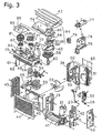
- FIG. 3 is an exploded perspective view of the outdoor unit.
- FIG. 4(a) is a side-view schematic diagram of the humidifying unit.
- FIG. 4(b) is a side-view schematic diagram of the humidifying unit according to another embodiment.
- FIG. 5 is a side-view schematic diagram of the humidifying unit according to another embodiment.
- FIG. 1 shows an external view of the air conditioner that uses a humidifying rotor (humidity regulating element) according to one embodiment of the present invention.
- An air conditioner 1 comprises an indoor unit 2, which is affixed to, e.g., an indoor wall, and an outdoor unit 3, which is installed in the outdoor space.
- the outdoor unit 3 comprises an outdoor air conditioning unit 5 that houses, e.g., an outdoor heat exchanger and an outdoor fan; and a humidifying unit 4 that transports humidified air to the indoor unit 2.
- An indoor heat exchanger is housed in the indoor unit 2, and an outdoor heat exchanger is housed in the outdoor unit 3. Further, the heat exchangers, and a refrigerant passageway 6 that connects these heat exchangers, constitute the refrigerant circuit.
- an inlet passageway 7 is provided between the humidifying unit 4 and the indoor unit 2 in order to supply air from the humidifying unit 4 to the indoor unit 2 side.
- FIG. 2 is a schematic diagram of the refrigerant circuit used by the air conditioner 1.
- An indoor heat exchanger 11 is provided in the indoor unit 2.
- This indoor heat exchanger 11 comprises a heat transfer tube that is folded multiple times at both ends in the longitudinal direction, and a plurality of fans that are inserted in the heat conducting tube, and heat is exchanged between the indoor heat exchanger 11 and the air that contacts the indoor heat exchanger 11.
- a cross flow fan 12 and an indoor fan motor 13 that rotatably drives the cross flow fan 12, are provided in the indoor unit 2.
- the cross flow fan 12 is cylindrically shaped, is provided with blades at the perimeter in the direction of the axis of rotation, and generates an air flow in a direction that intersects the axis of rotation.
- the cross flow fan 12 sucks indoor air into the indoor unit 2, exchanges heat with the indoor heat exchanger 11, and then blows the air out into the indoor space.
- the outdoor air conditioning unit 5 comprises a compressor 21, a four-way switching valve 22 that is connected to the compressor 21 on the discharge side, an accumulator 23 that is connected to the compressor 21 on the inlet side, an outdoor heat exchanger 24 that is connected to the four-way switching valve 22, and a motor-operated valve 25 that is connected to the outdoor heat exchanger 24.
- the motor-operated valve 25 is connected to a passageway 31 via a filter 26 and a liquid shutoff valve 27, and is connected to one end of the indoor heat exchanger 11 via the passageway 31.
- the four-way switching valve 22 is connected to a passageway 32 via a gas shutoff valve 28, and is connected to the other end of the indoor heat exchanger 11 via the passageway 32.
- These passageways 31, 32 correspond to the refrigerant passageway 6 shown in FIG. 1.
- an outdoor fan 29 for externally discharging the air after exchanging heat with the outdoor heat exchanger 24 is provided in the outdoor air conditioning unit 5.
- This outdoor fan 29 is rotatably driven by an outdoor fan motor 30.
- the outdoor unit 3 comprises a lower outdoor air conditioning unit 5 and an upper humidifying unit 4, and is provided with an outdoor unit casing that includes a bottom plate 41, a right-side plate 42, a left-side plate 43, a front plate 44, a protective mesh 46, a top plate 47, a humidifying unit casing 48, and the like.
- a fan inlet 45 and a partition plate 49 are affixed rearward of the front plate 44.
- the outdoor heat exchanger 24, which is approximately L-shaped when viewed from a plan view, is affixed to the front side of the protective mesh 46, which is positioned at the rear side of the outdoor unit casing.
- a fan motor mount 50 for securing the outdoor fan motor 30, is affixed to the front side of the outdoor heat exchanger 24.
- the outdoor fan motor 30 is provided in order to rotate the outdoor fan 29.
- the outdoor fan 29 provides negative pressure in the space formed by the fan inlet 45, the partition plate 49, the left-side plate 43, the outdoor heat exchanger 24, and the bottom plate of the humidifying unit casing 48. Further, the outdoor fan 29 plays the role of bringing the air introduced from the rear side and the left side of the outdoor unit casing into contact with the outdoor heat exchanger 24, and exhausts that air forward of the front plate 44.
- the refrigerant circuit components such as the compressor 21, the four-way switching valve 22, the motor-operated valve 25, the liquid shutoff valve 27, and the gas shutoff valve 28; and a thermistor 51, which detects the temperature of each part; are disposed between the partition plate 49 and the right-side plate 42.
- a shutoff valve cover 52 for protecting the liquid shutoff valve 27 and the gas shutoff valve 28 is affixed rightward of the right-side plate 42.
- the electrical equipment box 53 is affixed above the outdoor fan 29.
- the electrical equipment box 53 houses a printed circuit board 54, on which is mounted electrical parts (electrical equipment) for controlling each part, and a radiating fin 55 for radiating the heat generated by the electrical parts.
- the humidifying unit 4 is provided with the humidifying unit casing 48 positioned at the upper part of the outdoor unit 3.
- the right side of the inside of the humidifying unit casing 48 is a space that houses a humidifying rotor 58, and the like; and the left side is an adsorbing fan housing space 75 that houses an adsorbing fan 81, and the like.
- the humidifying rotor 58, a heater assembly 64, a humidifying fan 70, a cover member 74, the adsorbing fan 81, and the like, are arranged in the humidifying unit casing 48.
- the humidifying rotor 58 is a ceramic rotor with a honeycomb construction having an approximate disc shape, and is structured so that it can easily transit air. Specifically, as shown in FIG. 3, the rotor has a circular shape when viewed from the plan view, and has a fine honeycomb shape when viewed from a cross sectional view that cuts the horizontal plane. Further, air can pass through the numerous cylindrical parts of the humidifying rotor 58, whose cross section is a polygon.
- the principal part of the humidifying rotor 58 is baked from an adsorbent material like zeolite.
- zeolite is used herein, it is also possible to use adsorbent materials like silica gel and alumina.
- An adsorbent material like zeolite is characterized in that it adsorbs moisture in the air that it contacts, and desorbs the adsorbed moisture upon heating.
- the humidifying rotor 58 is constituted so that it supports a deodorizing catalyst that decomposes the odor of methyl sulfide, ammonia, trimethylamine, and the like, into an odorless component.
- the deodorizing catalyst includes an aqueous solution of the abovementioned zeolite, and the humidifying rotor 58 is made to support the deodorizing catalyst by a method wherein the deodorizing catalyst is incorporated in a ceramic that forms the base.
- the humidifying rotor 58 is rotatably supported via a rotor guide 60 around a support shaft 59 provided on the humidifying unit casing 48 side of the humidifying rotor 58.
- a gear is formed at the rim of the humidifying rotor 58, which meshes with a rotor drive gear 62 that is attached to the drive shaft of a rotor drive motor 61.
- the heater assembly 64 is disposed so that it covers approximately half (the right-side half) of the top side of the humidifying rotor 58.
- the heater assembly 64 comprises a heater main body 66, an upper cover 65 that covers the heater main body 66, and a lower cover 69.
- An inlet 67 for sucking in air, and an outlet 68 for discharging air heated by the heater main body 66 to the humidifying rotor 58 side, are formed in the lower cover 69.
- the heater assembly 64 is attached above the humidifying rotor 58 via a heater stationary plate 63.
- the humidifying fan 70 is below the humidifying rotor 58, and is disposed at a position opposing the heater assembly 64.
- the humidifying fan 70 is a centrifugal fan that is disposed in a space linked to a communicating duct 72 (a space below the outlet 68 of the lower cover 69 of the heater assembly 64). Further, the humidifying fan 70 is monolithically provided with a humidifying fan inlet 71, which is attached below the humidifying rotor 58.
- the humidifying fan 70 exhausts to the communicating duct 72 side the air that passed through the humidifying rotor 58 and came down from the near-side portion of the approximately half portion on the right side of the humidifying rotor 58 (the portion positioned below the outlet 68 of the lower cover 69 of the heater assembly 64).
- the air that passes out of the communicating duct 72 is supplied to the indoor unit 2 via a humidifying hose 73 and the inlet passageway 7.
- a cover member 74 covers a portion (the approximately half portion on the left side) where the heater assembly 64 is not positioned on the top side of the humidifying rotor 58.
- the cover member 74 along with an adsorbing-side bell mouth 84 (discussed later), forms an air passageway that passes from the top side of the left half portion of the humidifying rotor 58 to the upper part of the adsorbing fan housing space 75, which is explained below.
- the adsorbing fan 81 which is housed in the adsorbing fan housing space 75, is a centrifugal fan that is rotated by an adsorbing fan motor 83. Further, the adsorbing fan 81 sucks in air from an opening 85 of the adsorbing-side bell mouth 84 disposed at the upper part thereof, and exhausts the air to the outside of the adsorbing fan housing space 75 (outside of the humidifying unit casing 48).
- the adsorbing-side bell mouth 84 is provided at the upper part of the adsorbing fan housing space 75, and plays the role of guiding to the adsorbing fan 81 the air that passes through the air passageway formed by the cover member 74.
- an adsorbing fan motor 83 is fixed in the humidifying unit casing 48 by a motor affixing block 82.
- the electrical equipment casing comprises an electrical equipment box 76, which houses a printed circuit board 78 therein, and a cover 77.
- the humidifying unit 4 air from the outside is taken into the humidifying unit casing 48 by rotationally driving the adsorbing fan 81.
- the air that entered into the humidifying unit casing 48 passes through at approximately half portion on the left side of the humidifying rotor 58, and is exhausted outwards from the adsorbing fan housing space 75 via the adsorbing fan 81 and an air passageway formed by the cover member 74 and the adsorbing-side bell mouth 84 (refer to FIG. 4).
- the humidifying rotor 58 adsorbs the moisture included in the air.
- the approximately half portion on the left side of the humidifying rotor 58 which adsorbed the moisture by the adsorbing process, becomes the approximately half portion on the right side of the humidifying rotor 58 by the rotation of the humidifying rotor 58.
- the adsorbed moisture moves to the portion of the humidifying rotor 58 positioned below the heater assembly 64 attendant with the rotation of the humidifying rotor 58.
- the moisture that has moved therein is desorbed, by the heat from the heater main body 66 of the heater assembly 64 into the air flow generated by the humidifying fan 70.
- the humidifying fan 70 exhausts to the communicating duct 72 side the air that passed through the humidifying rotor 58, as described above, and delivers that air to the indoor unit 2 via the humidifying hose 73 and the inlet passageway 7.
- the air delivered to the indoor unit 2 includes the moisture that was adsorbed in the humidifying rotor 58.
- the contained odor component is decomposed by the deodorizing catalyst, changing to a state in which almost no malodor is present.
- the air supplied from the humidifying unit 4 to the indoor unit 2 is mixed into the air-conditioned air that was blown out by the cross flow fan 12 into the indoor space.
- One control unit is arranged in each of the indoor unit 2, the outdoor air conditioning unit 5, and the humidifying unit 4, respectively.
- the control unit controls the operation of each motorized device in accordance with the operation mode, such as a heating operation, a cooling operation, a drying operation, a humidifying operation, and an air supplying operation.
- the control unit executes the humidifying operation if a humidify command is received from a remote control (not shown), or if it is judged that the humidifying operation is needed in accordance with a humidified automatic operation command from the remote control.
- the humidifying operation is also often performed together with the heating operation.
- the rotor drive motor 61, the heater main body 66, the motor that rotates the humidifying fan 70, and the adsorbing fan motor 83 are driven during the humidifying operation.
- the moisture included in the air externally introduced into the humidifying unit 4 by the rotation of the adsorbing fan 81 is adsorbed by the humidifying rotor 58, the air that was heated by the heater main body 66 passes through the humidifying rotor 58 by the rotation of the humidifying fan 70, and the air that includes the water that was desorbed from the humidifying rotor 58 is supplied to the indoor unit 2.
- heating by the heater main body 66 is controlled so that the a surface 58a (refer to FIG. 4 (a)) on the heater side of the humidifying rotor 58 reaches 100°C to 300°C.
- the purpose of heating control lies in adsorbing the moisture from the humidifying rotor 58.
- the control unit performs the air supplying operation.
- the outdoor air is supplied to the indoor unit 2 by rotating just the humidifying fan 70, without rotating the adsorbing fan 81.
- the outdoor air which in principal is taken in from outside of the humidifying unit 4 is supplied to the indoor unit 2 as is, without humidifying and without the moisture being newly adsorbed in the humidifying rotor 58.
- the deodorizing catalyst decomposes the odor component in the air when that air passes through the humidifying rotor 58, the air supplied to the indoor unit 2 includes almost no odor component.
- the heating of the humidifying rotor 58 by the heater main body 66 is controlled so that the temperature reaches a level wherein the decomposition (chemical reaction) of the odor component by the deodorizing catalyst included in the humidifying rotor 58 is promoted. Specifically, control is performed so that the electric power value flowing to the heater main body 66 becomes smaller during the air supplying operation than during the humidifying operation.
- the use of the humidity regulating element which monolithically comprises a catalyst and a moisture adsorbing and desorbing material according to the present invention, enables the polluting components in the air to be decreased by passing air through a humidity regulating element while controlling an increase in the size of the apparatus, i.e., a dehumidifier, a humidifier, a dehumidifier/humidifier, or an air conditioner, without providing a separate filter and the like.
Landscapes
- Engineering & Computer Science (AREA)
- Chemical & Material Sciences (AREA)
- Combustion & Propulsion (AREA)
- Mechanical Engineering (AREA)
- General Engineering & Computer Science (AREA)
- Health & Medical Sciences (AREA)
- Analytical Chemistry (AREA)
- Chemical Kinetics & Catalysis (AREA)
- General Health & Medical Sciences (AREA)
- General Chemical & Material Sciences (AREA)
- Oil, Petroleum & Natural Gas (AREA)
- Veterinary Medicine (AREA)
- Public Health (AREA)
- Epidemiology (AREA)
- Life Sciences & Earth Sciences (AREA)
- Animal Behavior & Ethology (AREA)
- Inorganic Chemistry (AREA)
- Organic Chemistry (AREA)
- Materials Engineering (AREA)
- Exhaust Gas Treatment By Means Of Catalyst (AREA)
- Central Air Conditioning (AREA)
- Disinfection, Sterilisation Or Deodorisation Of Air (AREA)
- Air Humidification (AREA)
- Drying Of Gases (AREA)
- Catalysts (AREA)
- Devices For Blowing Cold Air, Devices For Blowing Warm Air, And Means For Preventing Water Condensation In Air Conditioning Units (AREA)
- Air Filters, Heat-Exchange Apparatuses, And Housings Of Air-Conditioning Units (AREA)
Abstract
Description
Claims (11)
- A humidity regulating element (58), monolithically comprising:a moisture adsorbing and desorbing material for adsorbing and desorbing moisture from and to the air; anda catalyst for decreasing polluting components in the air.
- The humidity regulating element (58) as recited in Claim 1, wherein
said catalyst is a deodorizing catalyst that decomposes an odor in the air into an odorless component. - The humidity regulating element (58) as recited in Claim 1 or Claim 2, wherein
said catalyst changes a deleterious component in the air into an innocuous component. - The humidity regulating element (58) as recited in any one claim of Claim 1 through Claim 3, wherein
at least a portion of said catalyst is a photocatalyst. - The humidity regulating element (58) as recited in any one claim of Claim 1 through Claim 4, wherein
said moisture adsorbing and desorbing material is present approximately uniformly over the entirety of said humidity regulating element, and said catalyst is present in a portion of said humidity regulating element. - A humidity regulator, comprising:the humidity regulating element (58) as recited in Claim 4;a lamp (90) that irradiates said humidity regulating element (58) with light having a wavelength in a predetermined range; anda fan (70) that passes air through said humidity regulating element.
- A humidity regulator (1), comprising:the humidity regulating element (58) as recited in Claim 4; anda casing (48) that covers said humidity regulating element; wherein,an opening (48a) is formed in said casing (48) so that light having a wavelength in a predetermined range impinges directly or after reflection upon said humidity regulating element (58).
- A humidifying unit (4) of an air conditioner (1) for adding humidified air to the regulated air supplied to an indoor space, comprising:the humidity regulating element (58) as recited in any one claim of Claim 1 through Claim 5;a heater (66) that heats said humidity regulating element; anda fan (70) that passes air through said humidity regulating element.
- The humidifying unit of the air conditioner as recited in Claim 8, wherein
most of said catalyst is included in a portion on said heater (66) side of said humidity regulating element (58). - The humidifying unit (4) of the air conditioner (1) as recited in Claim 8 or Claim 9, wherein
said humidifying unit (4) is a unit that takes in air from the outdoor space, and supplies that air to the indoor space;
said air conditioner (1) can perform a humidifying operation, wherein humidified air from said humidifying unit (4) is supplied to the indoor space, and an air supplying operation, wherein non-humidified air from said humidifying unit (4) is supplied to the indoor space; and
said heater (66) executes a first heating control mode for desorbing moisture from said humidity regulating element (58) when in said humidifying operation, and executes a second heating control mode for promoting the function of said catalyst of said humidity regulating element (58) when in said air supplying operation. - The humidifying unit (4) of the air conditioner (1) as recited in Claim 8, wherein
said air conditioner (1) comprises an indoor unit (2) and an outdoor unit (3); and
said humidity regulating element (58) is the humidity regulating element (58) as recited in Claim 4, and is provided in said outdoor unit (3).
Applications Claiming Priority (3)
| Application Number | Priority Date | Filing Date | Title |
|---|---|---|---|
| JP2001364229A JP2003164721A (en) | 2001-11-29 | 2001-11-29 | Humidification unit of air conditioner |
| JP2001364229 | 2001-11-29 | ||
| PCT/JP2002/010503 WO2003048648A1 (en) | 2001-11-29 | 2002-10-09 | Humidity conditioning element, humidity conditioner, and humidification unit of air conditioner |
Publications (3)
| Publication Number | Publication Date |
|---|---|
| EP1450112A1 true EP1450112A1 (en) | 2004-08-25 |
| EP1450112A4 EP1450112A4 (en) | 2008-01-23 |
| EP1450112B1 EP1450112B1 (en) | 2011-09-28 |
Family
ID=19174455
Family Applications (1)
| Application Number | Title | Priority Date | Filing Date |
|---|---|---|---|
| EP02772985A Expired - Lifetime EP1450112B1 (en) | 2001-11-29 | 2002-10-09 | A humidifying unit of an air conditioner, and an air conditioner comprising the humidifying unit |
Country Status (8)
| Country | Link |
|---|---|
| EP (1) | EP1450112B1 (en) |
| JP (1) | JP2003164721A (en) |
| KR (1) | KR100553415B1 (en) |
| CN (1) | CN100436950C (en) |
| AT (1) | ATE526544T1 (en) |
| AU (1) | AU2002338170B2 (en) |
| ES (1) | ES2371631T3 (en) |
| WO (1) | WO2003048648A1 (en) |
Cited By (2)
| Publication number | Priority date | Publication date | Assignee | Title |
|---|---|---|---|---|
| EP2364419A4 (en) * | 2008-11-28 | 2012-05-02 | Lg Electronics Inc | Humidifier |
| ITMI20131173A1 (en) * | 2013-07-11 | 2015-01-12 | Fulvio Perrone | EQUIPMENT AND METHOD OF DEODORIZATION FOR ROOMS |
Families Citing this family (18)
| Publication number | Priority date | Publication date | Assignee | Title |
|---|---|---|---|---|
| KR100598220B1 (en) * | 2004-05-21 | 2006-07-07 | 엘지전자 주식회사 | Outdoor unit of air conditioner |
| JP2005344986A (en) * | 2004-06-02 | 2005-12-15 | Daikin Ind Ltd | Humidifier, air conditioner, and air purifier with humidification function |
| JP4696567B2 (en) * | 2005-01-21 | 2011-06-08 | パナソニック株式会社 | Hygroscopic filter and humidifier |
| JP5234205B2 (en) * | 2011-06-01 | 2013-07-10 | ダイキン工業株式会社 | Air conditioner outdoor unit |
| JP5532099B2 (en) * | 2012-09-28 | 2014-06-25 | ダイキン工業株式会社 | Air conditioner outdoor unit |
| JP5532100B2 (en) * | 2012-09-28 | 2014-06-25 | ダイキン工業株式会社 | Air conditioner outdoor unit |
| JP6103937B2 (en) * | 2012-12-29 | 2017-03-29 | シャープ株式会社 | Humidifier |
| JP5800074B2 (en) * | 2013-09-30 | 2015-10-28 | ダイキン工業株式会社 | Unit outside air conditioning room |
| JP5910697B2 (en) * | 2014-10-20 | 2016-04-27 | ダイキン工業株式会社 | Air conditioner outdoor unit |
| JP6119823B2 (en) * | 2014-12-18 | 2017-04-26 | ダイキン工業株式会社 | Air conditioner outdoor unit |
| JP2018179362A (en) * | 2017-04-07 | 2018-11-15 | ダイキン工業株式会社 | Humidity control unit |
| WO2018230295A1 (en) * | 2017-06-14 | 2018-12-20 | ダイキン工業株式会社 | Humidity adjustment unit |
| CN112303743B (en) * | 2019-07-29 | 2022-05-13 | 青岛海尔空调器有限总公司 | Device for humidifying and absorbing aldehyde and air conditioner |
| CN112443895B (en) * | 2019-08-28 | 2022-04-19 | 青岛海尔空调器有限总公司 | Humidifying device and air conditioner |
| CN110762643B (en) * | 2019-09-30 | 2022-07-19 | 青岛海尔空调器有限总公司 | Outdoor machine of air conditioner |
| CN111336575B (en) * | 2020-03-18 | 2021-07-27 | 慈溪市迈南电器有限公司 | Comfortable and safe household heating system |
| CN112728685B (en) * | 2020-12-31 | 2022-11-15 | 浙江会众环境工程有限公司 | Air humidifier with formaldehyde removing function |
| JP7587158B2 (en) * | 2021-11-09 | 2024-11-20 | ダイキン工業株式会社 | Air supply equipment and outdoor units of air conditioners |
Family Cites Families (8)
| Publication number | Priority date | Publication date | Assignee | Title |
|---|---|---|---|---|
| FR2170993A1 (en) * | 1972-02-10 | 1973-09-21 | Kachita Co Ltd | Carbon monoxide oxidn in air - using catalyst chamber preceded and followed by drying chambers |
| WO1992009355A1 (en) * | 1990-11-27 | 1992-06-11 | Toto Ltd. | Method of treating air with discs in multilayer structure |
| US5733451A (en) * | 1994-05-20 | 1998-03-31 | Englehard/Icc | Core for interacting with a fluid media flowing therethrough and method of making the same |
| JPH08219479A (en) * | 1995-02-17 | 1996-08-30 | Komatsu Ltd | Blower |
| JP3120964B2 (en) * | 1995-12-19 | 2000-12-25 | シャープ株式会社 | Air conditioner |
| JP2000291978A (en) * | 1999-04-06 | 2000-10-20 | Daikin Ind Ltd | Air conditioner |
| JP2001065922A (en) * | 1999-08-30 | 2001-03-16 | Daikin Ind Ltd | Total heat exchanger |
| JP4356182B2 (en) * | 2000-03-24 | 2009-11-04 | ダイキン工業株式会社 | Air conditioning system |
-
2001
- 2001-11-29 JP JP2001364229A patent/JP2003164721A/en active Pending
-
2002
- 2002-10-09 KR KR1020037015075A patent/KR100553415B1/en not_active Expired - Fee Related
- 2002-10-09 ES ES02772985T patent/ES2371631T3/en not_active Expired - Lifetime
- 2002-10-09 CN CNB02805671XA patent/CN100436950C/en not_active Expired - Fee Related
- 2002-10-09 AU AU2002338170A patent/AU2002338170B2/en not_active Ceased
- 2002-10-09 WO PCT/JP2002/010503 patent/WO2003048648A1/en not_active Ceased
- 2002-10-09 AT AT02772985T patent/ATE526544T1/en not_active IP Right Cessation
- 2002-10-09 EP EP02772985A patent/EP1450112B1/en not_active Expired - Lifetime
Cited By (3)
| Publication number | Priority date | Publication date | Assignee | Title |
|---|---|---|---|---|
| EP2364419A4 (en) * | 2008-11-28 | 2012-05-02 | Lg Electronics Inc | Humidifier |
| US8672299B2 (en) | 2008-11-28 | 2014-03-18 | Lg Electronics Inc. | Humidifier |
| ITMI20131173A1 (en) * | 2013-07-11 | 2015-01-12 | Fulvio Perrone | EQUIPMENT AND METHOD OF DEODORIZATION FOR ROOMS |
Also Published As
| Publication number | Publication date |
|---|---|
| WO2003048648A1 (en) | 2003-06-12 |
| ES2371631T3 (en) | 2012-01-05 |
| CN1494646A (en) | 2004-05-05 |
| AU2002338170A1 (en) | 2003-06-17 |
| KR20040023602A (en) | 2004-03-18 |
| ATE526544T1 (en) | 2011-10-15 |
| EP1450112A4 (en) | 2008-01-23 |
| CN100436950C (en) | 2008-11-26 |
| EP1450112B1 (en) | 2011-09-28 |
| JP2003164721A (en) | 2003-06-10 |
| AU2002338170B2 (en) | 2004-07-15 |
| KR100553415B1 (en) | 2006-02-20 |
Similar Documents
| Publication | Publication Date | Title |
|---|---|---|
| AU2002338170B2 (en) | Humidity conditioning element, humidity conditioner, and humidification unit of air conditioner | |
| US10207017B2 (en) | Deodorizer | |
| US8773838B2 (en) | Sterilization method, ion generating device, ion generating apparatus, and air conditioning apparatus | |
| JP3608548B2 (en) | Ventilator and air conditioner | |
| JPH10267331A (en) | Humidifier | |
| JP5494340B2 (en) | Humidifier | |
| JP3863360B2 (en) | Air conditioner | |
| JP2002089902A (en) | Air conditioner | |
| JP4466306B2 (en) | Ventilator and building | |
| JP2005155977A (en) | Air conditioner, humidified air delivery path member and connection unit | |
| JP2003172527A (en) | Humidity control device and air conditioner using the same | |
| JP3120964B2 (en) | Air conditioner | |
| JP2007101140A (en) | Air conditioner | |
| JP3903726B2 (en) | Air conditioner | |
| JP2006145183A (en) | Air conditioner using highly functional photocatalyst | |
| JP2024041238A (en) | Air conditioner and control method for air conditioner | |
| KR200334100Y1 (en) | electric heat exchange -type ventilation apparatus | |
| KR20230089341A (en) | Photocatalyst and ventilation module near by revitalizing light source | |
| JP5488308B2 (en) | Humidifier | |
| JP3312588B2 (en) | Air conditioner | |
| JP2003161477A (en) | Humidifier | |
| WO2007040217A1 (en) | Humidifying unit and outdoor machine of air conditioner | |
| JPS63306341A (en) | Humidity adjustment device | |
| JPH08271048A (en) | Deodorizing unit with humidifying heating | |
| WO2026020526A1 (en) | Air purification device, indoor unit and air conditioner |
Legal Events
| Date | Code | Title | Description |
|---|---|---|---|
| PUAI | Public reference made under article 153(3) epc to a published international application that has entered the european phase |
Free format text: ORIGINAL CODE: 0009012 |
|
| 17P | Request for examination filed |
Effective date: 20030829 |
|
| AK | Designated contracting states |
Kind code of ref document: A1 Designated state(s): AT BE BG CH CY CZ DE DK EE ES FI FR GB GR IE IT LI LU MC NL PT SE SK TR |
|
| A4 | Supplementary search report drawn up and despatched |
Effective date: 20071227 |
|
| 17Q | First examination report despatched |
Effective date: 20091008 |
|
| GRAP | Despatch of communication of intention to grant a patent |
Free format text: ORIGINAL CODE: EPIDOSNIGR1 |
|
| GRAS | Grant fee paid |
Free format text: ORIGINAL CODE: EPIDOSNIGR3 |
|
| GRAA | (expected) grant |
Free format text: ORIGINAL CODE: 0009210 |
|
| RTI1 | Title (correction) |
Free format text: A HUMIDIFYING UNIT OF AN AIR CONDITIONER, AND AN AIR CONDITIONER COMPRISING THE HUMIDIFYING UNIT |
|
| AK | Designated contracting states |
Kind code of ref document: B1 Designated state(s): AT BE BG CH CY CZ DE DK EE ES FI FR GB GR IE IT LI LU MC NL PT SE SK TR |
|
| REG | Reference to a national code |
Ref country code: GB Ref legal event code: FG4D |
|
| REG | Reference to a national code |
Ref country code: CH Ref legal event code: EP |
|
| REG | Reference to a national code |
Ref country code: IE Ref legal event code: FG4D |
|
| REG | Reference to a national code |
Ref country code: DE Ref legal event code: R096 Ref document number: 60241163 Country of ref document: DE Effective date: 20111124 |
|
| REG | Reference to a national code |
Ref country code: ES Ref legal event code: FG2A Ref document number: 2371631 Country of ref document: ES Kind code of ref document: T3 Effective date: 20120105 |
|
| REG | Reference to a national code |
Ref country code: NL Ref legal event code: VDEP Effective date: 20110928 |
|
| PG25 | Lapsed in a contracting state [announced via postgrant information from national office to epo] |
Ref country code: SE Free format text: LAPSE BECAUSE OF FAILURE TO SUBMIT A TRANSLATION OF THE DESCRIPTION OR TO PAY THE FEE WITHIN THE PRESCRIBED TIME-LIMIT Effective date: 20110928 Ref country code: FI Free format text: LAPSE BECAUSE OF FAILURE TO SUBMIT A TRANSLATION OF THE DESCRIPTION OR TO PAY THE FEE WITHIN THE PRESCRIBED TIME-LIMIT Effective date: 20110928 |
|
| PG25 | Lapsed in a contracting state [announced via postgrant information from national office to epo] |
Ref country code: CY Free format text: LAPSE BECAUSE OF FAILURE TO SUBMIT A TRANSLATION OF THE DESCRIPTION OR TO PAY THE FEE WITHIN THE PRESCRIBED TIME-LIMIT Effective date: 20110928 Ref country code: GR Free format text: LAPSE BECAUSE OF FAILURE TO SUBMIT A TRANSLATION OF THE DESCRIPTION OR TO PAY THE FEE WITHIN THE PRESCRIBED TIME-LIMIT Effective date: 20111229 Ref country code: AT Free format text: LAPSE BECAUSE OF FAILURE TO SUBMIT A TRANSLATION OF THE DESCRIPTION OR TO PAY THE FEE WITHIN THE PRESCRIBED TIME-LIMIT Effective date: 20110928 |
|
| REG | Reference to a national code |
Ref country code: AT Ref legal event code: MK05 Ref document number: 526544 Country of ref document: AT Kind code of ref document: T Effective date: 20110928 |
|
| PG25 | Lapsed in a contracting state [announced via postgrant information from national office to epo] |
Ref country code: BE Free format text: LAPSE BECAUSE OF FAILURE TO SUBMIT A TRANSLATION OF THE DESCRIPTION OR TO PAY THE FEE WITHIN THE PRESCRIBED TIME-LIMIT Effective date: 20110928 |
|
| PG25 | Lapsed in a contracting state [announced via postgrant information from national office to epo] |
Ref country code: CZ Free format text: LAPSE BECAUSE OF FAILURE TO SUBMIT A TRANSLATION OF THE DESCRIPTION OR TO PAY THE FEE WITHIN THE PRESCRIBED TIME-LIMIT Effective date: 20110928 Ref country code: SK Free format text: LAPSE BECAUSE OF FAILURE TO SUBMIT A TRANSLATION OF THE DESCRIPTION OR TO PAY THE FEE WITHIN THE PRESCRIBED TIME-LIMIT Effective date: 20110928 |
|
| PG25 | Lapsed in a contracting state [announced via postgrant information from national office to epo] |
Ref country code: MC Free format text: LAPSE BECAUSE OF NON-PAYMENT OF DUE FEES Effective date: 20111031 Ref country code: PT Free format text: LAPSE BECAUSE OF FAILURE TO SUBMIT A TRANSLATION OF THE DESCRIPTION OR TO PAY THE FEE WITHIN THE PRESCRIBED TIME-LIMIT Effective date: 20120130 Ref country code: NL Free format text: LAPSE BECAUSE OF FAILURE TO SUBMIT A TRANSLATION OF THE DESCRIPTION OR TO PAY THE FEE WITHIN THE PRESCRIBED TIME-LIMIT Effective date: 20110928 Ref country code: EE Free format text: LAPSE BECAUSE OF FAILURE TO SUBMIT A TRANSLATION OF THE DESCRIPTION OR TO PAY THE FEE WITHIN THE PRESCRIBED TIME-LIMIT Effective date: 20110928 |
|
| REG | Reference to a national code |
Ref country code: CH Ref legal event code: PL |
|
| PG25 | Lapsed in a contracting state [announced via postgrant information from national office to epo] |
Ref country code: CH Free format text: LAPSE BECAUSE OF NON-PAYMENT OF DUE FEES Effective date: 20111031 Ref country code: DK Free format text: LAPSE BECAUSE OF FAILURE TO SUBMIT A TRANSLATION OF THE DESCRIPTION OR TO PAY THE FEE WITHIN THE PRESCRIBED TIME-LIMIT Effective date: 20110928 Ref country code: LI Free format text: LAPSE BECAUSE OF NON-PAYMENT OF DUE FEES Effective date: 20111031 |
|
| REG | Reference to a national code |
Ref country code: IE Ref legal event code: MM4A |
|
| PLBE | No opposition filed within time limit |
Free format text: ORIGINAL CODE: 0009261 |
|
| STAA | Information on the status of an ep patent application or granted ep patent |
Free format text: STATUS: NO OPPOSITION FILED WITHIN TIME LIMIT |
|
| 26N | No opposition filed |
Effective date: 20120629 |
|
| REG | Reference to a national code |
Ref country code: DE Ref legal event code: R097 Ref document number: 60241163 Country of ref document: DE Effective date: 20120629 |
|
| PG25 | Lapsed in a contracting state [announced via postgrant information from national office to epo] |
Ref country code: IE Free format text: LAPSE BECAUSE OF NON-PAYMENT OF DUE FEES Effective date: 20111009 |
|
| PG25 | Lapsed in a contracting state [announced via postgrant information from national office to epo] |
Ref country code: LU Free format text: LAPSE BECAUSE OF NON-PAYMENT OF DUE FEES Effective date: 20111009 |
|
| PG25 | Lapsed in a contracting state [announced via postgrant information from national office to epo] |
Ref country code: BG Free format text: LAPSE BECAUSE OF FAILURE TO SUBMIT A TRANSLATION OF THE DESCRIPTION OR TO PAY THE FEE WITHIN THE PRESCRIBED TIME-LIMIT Effective date: 20111228 |
|
| PG25 | Lapsed in a contracting state [announced via postgrant information from national office to epo] |
Ref country code: TR Free format text: LAPSE BECAUSE OF FAILURE TO SUBMIT A TRANSLATION OF THE DESCRIPTION OR TO PAY THE FEE WITHIN THE PRESCRIBED TIME-LIMIT Effective date: 20110928 |
|
| REG | Reference to a national code |
Ref country code: FR Ref legal event code: PLFP Year of fee payment: 15 |
|
| PGFP | Annual fee paid to national office [announced via postgrant information from national office to epo] |
Ref country code: FR Payment date: 20160919 Year of fee payment: 15 |
|
| PGFP | Annual fee paid to national office [announced via postgrant information from national office to epo] |
Ref country code: ES Payment date: 20160913 Year of fee payment: 15 |
|
| PGFP | Annual fee paid to national office [announced via postgrant information from national office to epo] |
Ref country code: DE Payment date: 20161004 Year of fee payment: 15 Ref country code: GB Payment date: 20161005 Year of fee payment: 15 |
|
| PGFP | Annual fee paid to national office [announced via postgrant information from national office to epo] |
Ref country code: IT Payment date: 20161024 Year of fee payment: 15 |
|
| REG | Reference to a national code |
Ref country code: DE Ref legal event code: R119 Ref document number: 60241163 Country of ref document: DE |
|
| GBPC | Gb: european patent ceased through non-payment of renewal fee |
Effective date: 20171009 |
|
| REG | Reference to a national code |
Ref country code: FR Ref legal event code: ST Effective date: 20180629 |
|
| PG25 | Lapsed in a contracting state [announced via postgrant information from national office to epo] |
Ref country code: GB Free format text: LAPSE BECAUSE OF NON-PAYMENT OF DUE FEES Effective date: 20171009 Ref country code: DE Free format text: LAPSE BECAUSE OF NON-PAYMENT OF DUE FEES Effective date: 20180501 |
|
| PG25 | Lapsed in a contracting state [announced via postgrant information from national office to epo] |
Ref country code: FR Free format text: LAPSE BECAUSE OF NON-PAYMENT OF DUE FEES Effective date: 20171031 |
|
| PG25 | Lapsed in a contracting state [announced via postgrant information from national office to epo] |
Ref country code: IT Free format text: LAPSE BECAUSE OF NON-PAYMENT OF DUE FEES Effective date: 20171009 |
|
| REG | Reference to a national code |
Ref country code: ES Ref legal event code: FD2A Effective date: 20181220 |
|
| PG25 | Lapsed in a contracting state [announced via postgrant information from national office to epo] |
Ref country code: ES Free format text: LAPSE BECAUSE OF NON-PAYMENT OF DUE FEES Effective date: 20171010 |