EP1450065A1 - Silent damper with anti-rattle shaft - Google Patents
Silent damper with anti-rattle shaft Download PDFInfo
- Publication number
- EP1450065A1 EP1450065A1 EP04012844A EP04012844A EP1450065A1 EP 1450065 A1 EP1450065 A1 EP 1450065A1 EP 04012844 A EP04012844 A EP 04012844A EP 04012844 A EP04012844 A EP 04012844A EP 1450065 A1 EP1450065 A1 EP 1450065A1
- Authority
- EP
- European Patent Office
- Prior art keywords
- damper
- groove
- disk
- housing
- piston
- Prior art date
- Legal status (The legal status is an assumption and is not a legal conclusion. Google has not performed a legal analysis and makes no representation as to the accuracy of the status listed.)
- Granted
Links
Images


Classifications
-
- F—MECHANICAL ENGINEERING; LIGHTING; HEATING; WEAPONS; BLASTING
- F16—ENGINEERING ELEMENTS AND UNITS; GENERAL MEASURES FOR PRODUCING AND MAINTAINING EFFECTIVE FUNCTIONING OF MACHINES OR INSTALLATIONS; THERMAL INSULATION IN GENERAL
- F16F—SPRINGS; SHOCK-ABSORBERS; MEANS FOR DAMPING VIBRATION
- F16F9/00—Springs, vibration-dampers, shock-absorbers, or similarly-constructed movement-dampers using a fluid or the equivalent as damping medium
- F16F9/32—Details
- F16F9/36—Special sealings, including sealings or guides for piston-rods
- F16F9/368—Sealings in pistons
-
- F—MECHANICAL ENGINEERING; LIGHTING; HEATING; WEAPONS; BLASTING
- F16—ENGINEERING ELEMENTS AND UNITS; GENERAL MEASURES FOR PRODUCING AND MAINTAINING EFFECTIVE FUNCTIONING OF MACHINES OR INSTALLATIONS; THERMAL INSULATION IN GENERAL
- F16F—SPRINGS; SHOCK-ABSORBERS; MEANS FOR DAMPING VIBRATION
- F16F9/00—Springs, vibration-dampers, shock-absorbers, or similarly-constructed movement-dampers using a fluid or the equivalent as damping medium
- F16F9/02—Springs, vibration-dampers, shock-absorbers, or similarly-constructed movement-dampers using a fluid or the equivalent as damping medium using gas only or vacuum
- F16F9/0209—Telescopic
-
- F—MECHANICAL ENGINEERING; LIGHTING; HEATING; WEAPONS; BLASTING
- F16—ENGINEERING ELEMENTS AND UNITS; GENERAL MEASURES FOR PRODUCING AND MAINTAINING EFFECTIVE FUNCTIONING OF MACHINES OR INSTALLATIONS; THERMAL INSULATION IN GENERAL
- F16F—SPRINGS; SHOCK-ABSORBERS; MEANS FOR DAMPING VIBRATION
- F16F9/00—Springs, vibration-dampers, shock-absorbers, or similarly-constructed movement-dampers using a fluid or the equivalent as damping medium
- F16F9/32—Details
- F16F9/3207—Constructional features
-
- F—MECHANICAL ENGINEERING; LIGHTING; HEATING; WEAPONS; BLASTING
- F16—ENGINEERING ELEMENTS AND UNITS; GENERAL MEASURES FOR PRODUCING AND MAINTAINING EFFECTIVE FUNCTIONING OF MACHINES OR INSTALLATIONS; THERMAL INSULATION IN GENERAL
- F16F—SPRINGS; SHOCK-ABSORBERS; MEANS FOR DAMPING VIBRATION
- F16F9/00—Springs, vibration-dampers, shock-absorbers, or similarly-constructed movement-dampers using a fluid or the equivalent as damping medium
- F16F9/32—Details
- F16F9/54—Arrangements for attachment
-
- B—PERFORMING OPERATIONS; TRANSPORTING
- B60—VEHICLES IN GENERAL
- B60G—VEHICLE SUSPENSION ARRANGEMENTS
- B60G2204/00—Indexing codes related to suspensions per se or to auxiliary parts
- B60G2204/40—Auxiliary suspension parts; Adjustment of suspensions
- B60G2204/43—Fittings, brackets or knuckles
- B60G2204/4305—Bracket for mounting of hydraulic lines on a damper cylinder
Definitions
- This invention pertains to a damper according to the preamble of claim 1.
- a damper of this kind is known from US 5,518,223.
- the cap of the damper disclosed in the Hiramoto reference is substantially inelastic and therefore is susceptible to rattle and does not provide for any rotation of the piston shaft which is of rectangular cross section. Moreover, a damper with such a cap does not compensate for misalignment of the glovebox or allow for a simple adjustment from a right-hand part to a left-hand part.
- a damper with a piston formed by two disks separated by a spacer, the spacer being formed of longitudinally and radially extending planar portions with an X-shaped cross section. At least one of the distal ends of the planar portions of the spacer includes a groove which forms and air passageway.
- the groove extends to the periphery of the trailing disk of the piston.
- the groove may extend to a periphery of the leading disk of the piston but to a lesser depth.
- a seal rides on the distal ends of the planar portions of the spacer.
- the cap of the damper is formed from two O-rings.
- a first O-ring generally engages the periphery of the damper housing and passes through two grooves within periphery of the damper housing so that portions of the O-ring form a first pair of parallel chords within the circular cross section of the damper housing.
- a second O-ring is engaged by two opposed hooks on the mouth of the damper housing so as to form a second pair of parallel chords within the circular cross section of the damper housing.
- the second pair of parallel chords is oriented ninety degrees with respect to the first pair of parallel chords.
- the rectangular intersection of the two pairs of parallel chords formed by the O-rings supports the piston shaft of rectangular cross section.
- the resulting elastic configuration of the O-rings compensates for misalignment of the damper. Additionally, this elastic configuration allows a user or installer to simply rotate the piston by 180° within the damper housing in order to convert from a left-hand part to a right-hand part, and vice versa.
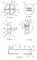
- Figures 1 and 2 are side plan views of the damper 10 of the present invention with the piston assembly 12 in the retracted and extended positions, respectively, in relation to the damper housing 14.
- Piston assembly 12 is shown in detail in Figures 4-8.
- piston assembly 12 includes piston shaft 13 attached to piston 15.
- piston shaft 13 is of an H-shaped or generally rectangular cross section.
- piston shaft 13 is further attached to head 17 for detent engaging a structural device, such as an automotive glovebox door (not shown).
- Piston 15 includes a leading disk 16 separated from a trailing disk 18 by a spacer configuration 20.
- Spacer configuration 20 as shown in Figure 5, includes planar portions 22, 24 which are oriented in a longitudinal and radial direction in a X cross section. Planar portions 22, 24 include distal ends 26, 28 and 30, 32, respectively which terminate inwardly adjacent from the periphery of leading disk 16 and trailing disk 18.
- Toroidal seal 34 with outwardly extending lip 35, is positioned between leading disk 16 and trailing disk 18.
- toroidal seal 34 has an inner diameter to engage and travel upon distal ends 26, 28, 30, 32 (see Figure 8 wherein toroidal seal 34 is shown in phantom at the two extremes of the range of travel thereof).
- Lip 35 of toroidal seal 34 has an outer diameter greater than that of leading and trailing disks 16, 18 so as to sealing engage the interior of damper housing 14.
- Leading and trailing disks 16, 18 preferably do not form a sealing engagement with the interior of damper housing 14.
- a radially outward facing portion of distal end 26 further includes selective air communication groove 36. While the illustrated embodiment includes selective air communication groove 36 on a single distal end 26, groove 36 could be included on multiple distal ends. Selective air communication groove 36 is in communication with groove 38 cut into trailing disk 18, extending from selective air communication groove 36 to a peripheral edge of trailing disk 18. Selective air communication groove 36 may also be in communication with reduced air communication groove 40. Reduced air communication groove 40 is cut into leading disk 16, extending from selective air communication groove 36 to a peripheral edge of leading disk 16. In order to achieve the directionally dependent damping, reduced air communication groove 36 must be of less depth (or at least reduced cross sectional area with attendant increased air flow resistance) with respect to groove 38 and selective air communication groove 36. Indeed, reduced air communication groove 40 may even be eliminated in order to achieve the greatest directional dependence of the damping.
- toroidal seal 34 slides to the rightward position against trailing disk 18 as shown in Figure 8. This allows air communication from the inner diameter of damper housing 14 to piston shaft 13 through selective air communication groove 36 and groove 38. This air communication eliminates or substantially reduces damping in this position of toroidal seal 34.
- damper housing 14 has cylindrical walls 42 and includes semi-circular fastener 44 for engaging a structural device, such as an automotive dashboard (not shown).
- Mouth 46 is an opening formed by cylindrical walls 42. Inwardly adjacent from mouth 46 are two opposed grooves 48, 50 cut across a chord of the periphery of cylindrical walls 42.
- first elastic O-ring 51 extends around portions of the 42 periphery of cylindrical walls 42 and through opposed grooves 48, 50 thereby forming two straight portions 52, 54 for support of piston shaft 13.
- immediately outward adjacent from opposed grooves 48, 50 are outwardly flanged hooks 56, 58, respectively.
- Second elastic O-ring 60 extends around outwardly flanged hooks 56, 58 thereby forming two straight portions 62, 64 which are perpendicular to straight portions 52, 54. This forms a rectangular area for guiding piston shaft 13 and allowing piston shaft 13 to slide therethrough. This configuration eliminates the necessity for a rigid cap, results in a configuration with very low noise or rattle, and further compensates for subsequent misalignment of piston shaft 13 with damper body 14 without binding. Additionally, this allows the installer to rotate piston shaft by 180° in order to reverse the orientation of head 17 from a right-hand configuration to a left-hand configuration and vice versa.
- Grooves 48, 50 and outwardly flanged hooks 56, 58 can be replaced with many similar protrusions or intrusions which can engage an O-ring as will be apparent to those skilled in the art.
- damper 10 While the steps for installation may be done in different orders, a typical order of installation would be that the damper 10 would be provided as an assembled device with the piston assembly 12 inserted into damper housing 14, first O-ring 51 passing through grooves 48, 50 and second O-ring 60 engaged by outwardly flanged hooks 56, 58 thereby slidably retaining piston shaft 13 (otherwise the installer would perform such assembly). The installer would twist piston shaft 13, if necessary, so that head 17 would have the correct orientation. The installer would then engage fastener 44 to a structural device, such as an automotive dashboard (not shown) and engage head 17 to another structural device, such as an automotive glovebox (not shown).
- a structural device such as an automotive dashboard (not shown)
- head 17 such as an automotive glovebox (not shown).
Landscapes
- Engineering & Computer Science (AREA)
- General Engineering & Computer Science (AREA)
- Mechanical Engineering (AREA)
- Fluid-Damping Devices (AREA)
- Vehicle Step Arrangements And Article Storage (AREA)
- Sealing Devices (AREA)
- Braking Arrangements (AREA)
Abstract
Description
Claims (12)
- A damper comprising:a housing (14) with cylindrical walls (42), an open end (46), and a closed end;a piston assembly (12) reciprocating within said housing (14), said piston assembly (12) including a piston shaft (13) with a first end extending through said open end (46) of said housing (14); characterized byfirst means for holding portions of at least a first elastic ring across said open end (46) to slidably retain said piston shaft (13).
- The damper of claim 1 wherein said first means for holding includes two peripherally opposed grooves (48,50) cut into said cylindrical walls (42) inwardly adjacent from said open end (46), said at least a first elastic ring (51) engaged by said two peripherally opposed grooves (48,50).
- The damper of claim 1 or 2 further including second means for holding portions of at least a second elastic ring (60) across said open end (46) to slidably retain said piston shaft (13).
- The damper of claim 3 wherein said portions of at least a first elastic ring (51) are perpendicular to said portions of at least a second elastic ring (60) thereby bounding a rectangular area through which said piston shaft (13) is slidably retained.
- The damper of claim 3 or 4 wherein said second means for holding includes hooks (56,58) outwardly adjacent from said peripherally opposed grooves (48,50).
- A damper of at least one of the preceding claims, further including a piston (15) attached to said first end of said piston shaft (13), said piston being formed from a leading disk (16) and a trailing disk (18) offset by a spacer (20);
said spacer (20) comprising projections (26,28,30,32) forming longitudinally oriented surfaces inwardly from a periphery of said leading disk (16) and said trailing disk (18) ;
at least one of said longitudinally oriented surfaces including a first groove (36);
said trailing disk (18) including a second groove (38) extending from said first groove (36) to a periphery of said trailing disk (18); and
a toroidal seal (34) with an inner surface slidably engaging said longitudinally oriented surfaces and an outer surface slidably engaging an interior of said cylindrical walls (42) of said housing (14), whereby when said piston assembly (12) is extended from said housing (14), said toroidal seal is urged toward said leading disk (16) thereby inhibiting airflow through said first groove (36) thereby damping movement of said piston assembly (12) and wherein when piston assembly (12) is driven into said housing (14), said toroidal seal (34) is urged toward said trailing disk (18) thereby allowing airflow through said first groove (36) and said second groove (38) thereby reducing damping of movement of said piston assembly (12). - The damper of Claim 6 wherein said leading disk (16) and said trailing disk (18) are free of sealing engagement with said interior of said cylindrical walls (42) of said housing (14) and wherein said outer surface of said toroidal seal sealingly and slidably engages said interior of said cylindrical walls (42) of said housing (14).
- The damper of Claim 6 or 7 wherein said projections extend along a portion of a radius of said leading disk (16) and said trailing disk (18).
- The damper of at least one of claims 6 to 8,further including a third groove (40) in said leading disk (16), said third groove (40) extending from said first groove (36) to a periphery of said leading disk (16), said third groove (40) having air flow resistance greater than an air flow resistance of said second groove (38).
- The damper of at least one of claims 6 to 9, wherein said toroidal seal (34) has an outwardly extending lip (35) sealingly and slidably engaging an interior of said cylindrical sidewalls (42).
- The damper of at least one of claims 6 to 10, wherein a second end of said piston shaft (13) includes a detent engagement device (17).
- The damper of at least one of claims 6 to 11, wherein said housing includes a fastener (44) on an exterior of said cylindrical walls (42).
Applications Claiming Priority (3)
| Application Number | Priority Date | Filing Date | Title |
|---|---|---|---|
| US177029 | 1998-10-22 | ||
| US09/177,029 US6199673B1 (en) | 1998-10-22 | 1998-10-22 | Silent damper with anti-rattle shaft |
| EP99115946A EP0995926B1 (en) | 1998-10-22 | 1999-08-13 | Silent damper with anti-rattle shaft |
Related Parent Applications (1)
| Application Number | Title | Priority Date | Filing Date |
|---|---|---|---|
| EP99115946.8 Division | 1999-08-13 |
Publications (2)
| Publication Number | Publication Date |
|---|---|
| EP1450065A1 true EP1450065A1 (en) | 2004-08-25 |
| EP1450065B1 EP1450065B1 (en) | 2005-11-02 |
Family
ID=22646895
Family Applications (2)
| Application Number | Title | Priority Date | Filing Date |
|---|---|---|---|
| EP99115946A Expired - Lifetime EP0995926B1 (en) | 1998-10-22 | 1999-08-13 | Silent damper with anti-rattle shaft |
| EP04012844A Expired - Lifetime EP1450065B1 (en) | 1998-10-22 | 1999-08-13 | Silent damper with anti-rattle shaft |
Family Applications Before (1)
| Application Number | Title | Priority Date | Filing Date |
|---|---|---|---|
| EP99115946A Expired - Lifetime EP0995926B1 (en) | 1998-10-22 | 1999-08-13 | Silent damper with anti-rattle shaft |
Country Status (4)
| Country | Link |
|---|---|
| US (2) | US6199673B1 (en) |
| EP (2) | EP0995926B1 (en) |
| CA (1) | CA2280746C (en) |
| DE (2) | DE69928742T2 (en) |
Cited By (1)
| Publication number | Priority date | Publication date | Assignee | Title |
|---|---|---|---|---|
| WO2013099764A1 (en) * | 2011-12-27 | 2013-07-04 | 株式会社ニフコ | Air damper |
Families Citing this family (19)
| Publication number | Priority date | Publication date | Assignee | Title |
|---|---|---|---|---|
| US6513811B1 (en) * | 1999-09-02 | 2003-02-04 | Illinois Tool Works Inc. | Air damper with graphite coated lip seal |
| US6726219B2 (en) * | 1999-09-02 | 2004-04-27 | Illinois Tool Works Inc. | Air damper with graphite coated lip seal |
| JP3513650B2 (en) * | 2000-01-07 | 2004-03-31 | 株式会社パイオラックス | Air damper |
| DE10021762B4 (en) * | 2000-05-04 | 2006-03-16 | Itw-Ateco Gmbh | Air damper for a movably mounted component, in particular in automobiles |
| JP3926580B2 (en) * | 2001-04-25 | 2007-06-06 | 株式会社パイオラックス | Switchgear |
| US6463911B1 (en) * | 2002-01-14 | 2002-10-15 | Visteon Global Technologies, Inc. | Fuel pressure damper |
| JP3994042B2 (en) * | 2002-09-20 | 2007-10-17 | 株式会社パイオラックス | String type air damper |
| JP4183516B2 (en) * | 2003-01-29 | 2008-11-19 | トックベアリング株式会社 | Linear damper |
| US20050040574A1 (en) * | 2003-08-19 | 2005-02-24 | Ivers Douglas E. | Pneumatic surface effect damper |
| US7314201B2 (en) * | 2005-01-07 | 2008-01-01 | La-Z-Boy Incorporated | Dampened retractable furniture cup holder |
| US7731140B2 (en) * | 2005-08-17 | 2010-06-08 | Carnevali Jeffrey D | Interchangeable snap-in device mounting apparatus |
| DE102006015605B4 (en) * | 2006-04-04 | 2009-10-15 | Stabilus Gmbh | piston assembly |
| DE102007014124B4 (en) * | 2007-03-23 | 2013-01-24 | Saf-Holland Gmbh | shock absorber |
| ATE542728T1 (en) * | 2009-11-20 | 2012-02-15 | Iwis Motorsysteme Gmbh & Co Kg | TENSIONING DEVICE WITH SWIVELING JOINT CONNECTION |
| JP5552412B2 (en) * | 2010-10-26 | 2014-07-16 | 株式会社ニフコ | Piston damper |
| DE102011106514B4 (en) * | 2011-06-15 | 2021-08-12 | Zf Airbag Germany Gmbh | Pyrotechnic actuator with ventilation, hood stand and belt tensioner with such an actuator |
| US9475421B2 (en) | 2013-10-23 | 2016-10-25 | Burton Technologies, Llc | Reflector damper bracket |
| DE102014115543A1 (en) * | 2014-10-25 | 2016-04-28 | Stabilus Gmbh | Piston / cylinder unit |
| EP4226056A4 (en) | 2020-10-05 | 2024-03-27 | ASYST Technologies L.P. | Adjustable linkage arm |
Citations (6)
| Publication number | Priority date | Publication date | Assignee | Title |
|---|---|---|---|---|
| US4629167A (en) * | 1983-07-14 | 1986-12-16 | Nifco, Inc. | Piston cylinder type damper |
| JPH02129424A (en) * | 1988-11-07 | 1990-05-17 | Nifco Inc | Cylinder type air damper |
| US4948103A (en) * | 1989-01-30 | 1990-08-14 | Illinois Tool Works, Inc. | Spring-loaded dampening actuator |
| US5165324A (en) * | 1990-10-16 | 1992-11-24 | Nifco Inc. | Piston-cylinder type air damper |
| US5518223A (en) * | 1994-12-29 | 1996-05-21 | Illinois Tool Works Inc. | Air damper assembly with piston seal and piston rod latch |
| US5697477A (en) * | 1994-10-07 | 1997-12-16 | Nifco Inc. | Air damper |
Family Cites Families (30)
| Publication number | Priority date | Publication date | Assignee | Title |
|---|---|---|---|---|
| US2830855A (en) * | 1955-02-02 | 1958-04-15 | Hyre Robert Warren | Scaffolding connection |
| FI194773A (en) | 1973-06-15 | 1974-12-16 | Veli Jaakko Saajos | |
| DE2619176C2 (en) * | 1976-04-30 | 1982-10-21 | Stabilus Gmbh, 5400 Koblenz | Gas spring with no extension force when the piston rod is retracted |
| JPS5753139U (en) * | 1980-09-11 | 1982-03-27 | ||
| US4428596A (en) * | 1982-03-12 | 1984-01-31 | Bell Tommy G | Trailer safety hitch |
| US4553484A (en) * | 1982-09-30 | 1985-11-19 | Cox Clayton E | Cornerboard for pallets |
| US4555126A (en) * | 1982-10-18 | 1985-11-26 | Mazda Motor Corporation | Vehicle suspension system |
| US4548389A (en) * | 1983-03-01 | 1985-10-22 | Fichtel & Sachs Industries, Inc. | Redundant high-pressure seal for fluid spring |
| FR2552055B1 (en) | 1983-09-19 | 1986-07-18 | Dba | DEVICE FOR MOUNTING A PROTECTIVE CAP ON A SUPPORT |
| DE3445211A1 (en) | 1984-12-12 | 1986-06-12 | Ford-Werke AG, 5000 Köln | STORAGE DEVICE WITHIN FAIRINGS IN MOTOR VEHICLES |
| DE3512161A1 (en) | 1985-04-03 | 1986-10-09 | Paul Vahle GmbH & Co KG, 4708 Kamen | PLASTIC RAIL BRACKET |
| DE3529422A1 (en) * | 1985-08-16 | 1987-02-26 | Stabilus Gmbh | GASKET FOR PNEUMATIC, HYDRAULIC OR HYDROPNEUMATIC AGGREGATE |
| US4669893A (en) | 1986-02-18 | 1987-06-02 | United Technologies Corporation | Annular oil damper arrangement |
| DE3628555A1 (en) | 1986-08-22 | 1988-02-25 | Daimler Benz Ag | BRAKE DEVICE FOR OPENING MOVEMENT OF FLAPS AND COVERS |
| DE3725101A1 (en) | 1987-07-29 | 1989-02-09 | Bauer Fritz & Soehne Ohg | PISTON FOR PISTON-CYLINDER UNIT |
| JPH0349453U (en) | 1989-09-22 | 1991-05-14 | ||
| US4989700A (en) | 1989-12-28 | 1991-02-05 | Fichtel & Sachs Industries, Inc. | Gas spring with an anti-rattle piston assembly |
| DE4321036A1 (en) | 1993-06-24 | 1995-01-05 | Fichtel & Sachs Ag | Vibration damper with extension limit stop mounting |
| US5398820A (en) | 1994-01-14 | 1995-03-21 | Kiss; Howard M. | Doll-holder wall mount |
| DE19501792C2 (en) | 1995-01-21 | 1997-06-12 | Fichtel & Sachs Ag | Piston with piston ring |
| DE19506479A1 (en) | 1995-02-24 | 1996-08-29 | Suspa Compart Ag | Fluid-filled cylinder-piston rod unit, in particular gas spring |
| US5741007A (en) | 1995-06-19 | 1998-04-21 | Illinois Tool Works Inc. | Damper rotational latch |
| GB2303193B (en) * | 1995-07-13 | 1998-10-14 | Draftex Ind Ltd | Gas spring |
| DE19533328C1 (en) | 1995-09-11 | 1996-09-26 | Fichtel & Sachs Ag | Vibration damper having piston in pressure tube |
| GB2305991B (en) * | 1995-10-09 | 1999-07-07 | Draftex Ind Ltd | Gas spring |
| US5756890A (en) | 1995-11-30 | 1998-05-26 | Ford Global Technologies, Inc. | Snap mount throttle position sensor |
| JPH09158967A (en) * | 1995-12-06 | 1997-06-17 | Showa:Kk | Gas spring |
| US5716154A (en) * | 1996-08-26 | 1998-02-10 | General Motors Corporation | Attachment device |
| US5934697A (en) * | 1996-12-02 | 1999-08-10 | Rockshox, Inc. | Fork suspension with oil bath lubrication |
| IT1287600B1 (en) * | 1996-12-19 | 1998-08-06 | Marzocchi Spa | ADJUSTABLE HYDROPNEUMATIC SHOCK ABSORBER, PARTICULARLY SUITABLE FOR FORMING THE LEGS OF A TELESCOPIC FORK FOR MOUNTAIN-BIKES. |
-
1998
- 1998-10-22 US US09/177,029 patent/US6199673B1/en not_active Expired - Lifetime
- 1998-11-24 US US09/199,994 patent/US6460666B1/en not_active Expired - Lifetime
-
1999
- 1999-08-13 DE DE69928742T patent/DE69928742T2/en not_active Expired - Lifetime
- 1999-08-13 EP EP99115946A patent/EP0995926B1/en not_active Expired - Lifetime
- 1999-08-13 EP EP04012844A patent/EP1450065B1/en not_active Expired - Lifetime
- 1999-08-13 DE DE69928143T patent/DE69928143T2/en not_active Expired - Lifetime
- 1999-08-26 CA CA002280746A patent/CA2280746C/en not_active Expired - Fee Related
Patent Citations (6)
| Publication number | Priority date | Publication date | Assignee | Title |
|---|---|---|---|---|
| US4629167A (en) * | 1983-07-14 | 1986-12-16 | Nifco, Inc. | Piston cylinder type damper |
| JPH02129424A (en) * | 1988-11-07 | 1990-05-17 | Nifco Inc | Cylinder type air damper |
| US4948103A (en) * | 1989-01-30 | 1990-08-14 | Illinois Tool Works, Inc. | Spring-loaded dampening actuator |
| US5165324A (en) * | 1990-10-16 | 1992-11-24 | Nifco Inc. | Piston-cylinder type air damper |
| US5697477A (en) * | 1994-10-07 | 1997-12-16 | Nifco Inc. | Air damper |
| US5518223A (en) * | 1994-12-29 | 1996-05-21 | Illinois Tool Works Inc. | Air damper assembly with piston seal and piston rod latch |
Non-Patent Citations (1)
| Title |
|---|
| PATENT ABSTRACTS OF JAPAN vol. 0143, no. 64 (M - 1007) 7 August 1990 (1990-08-07) * |
Cited By (4)
| Publication number | Priority date | Publication date | Assignee | Title |
|---|---|---|---|---|
| WO2013099764A1 (en) * | 2011-12-27 | 2013-07-04 | 株式会社ニフコ | Air damper |
| JP2013133893A (en) * | 2011-12-27 | 2013-07-08 | Nifco Inc | Air damper |
| CN104024681A (en) * | 2011-12-27 | 2014-09-03 | 株式会社利富高 | Air damper |
| CN104024681B (en) * | 2011-12-27 | 2016-10-05 | 株式会社利富高 | Air damper |
Also Published As
| Publication number | Publication date |
|---|---|
| DE69928742D1 (en) | 2006-01-12 |
| EP0995926B1 (en) | 2005-12-07 |
| DE69928143T2 (en) | 2006-04-20 |
| US6460666B1 (en) | 2002-10-08 |
| DE69928143D1 (en) | 2005-12-08 |
| CA2280746A1 (en) | 2000-04-22 |
| US6199673B1 (en) | 2001-03-13 |
| EP0995926A3 (en) | 2003-04-23 |
| EP0995926A2 (en) | 2000-04-26 |
| EP1450065B1 (en) | 2005-11-02 |
| CA2280746C (en) | 2004-03-30 |
| DE69928742T2 (en) | 2006-06-29 |
Similar Documents
| Publication | Publication Date | Title |
|---|---|---|
| EP1450065B1 (en) | Silent damper with anti-rattle shaft | |
| EP1152165B1 (en) | Air damper for a movably supported structural part, in particular in automobiles | |
| US10174847B2 (en) | Saw tooth design for control damper | |
| EP1593887B1 (en) | Flow rate control valve | |
| AU731364B2 (en) | Gas spring | |
| US4585026A (en) | Seal for coupling or valve assemblies | |
| US9062734B2 (en) | Shock absorber and vehicle using the same | |
| WO2010131682A1 (en) | Air damper | |
| GB2302720A (en) | Vibration damper | |
| US6220583B1 (en) | Air damper with hook on piston | |
| US5730263A (en) | Vibration damper | |
| US5095581A (en) | Variable position door holder and stop | |
| CN215059754U (en) | Noise-reduction one-way valve | |
| JP2547912Y2 (en) | Piston cylinder type air damper | |
| US20020125454A1 (en) | Spool valve for controlled dampers | |
| EP1182373B1 (en) | Air damper used in glove box of automobile | |
| KR0141855B1 (en) | Air damper | |
| US6000431A (en) | Servo valve | |
| MXPA99009683A (en) | Shock absorber with anti-rui axis | |
| CN114046328A (en) | Variable speed gas spring | |
| WO2020255879A1 (en) | Air damper | |
| EP1520996A2 (en) | Fluid-actuated rotary drive | |
| CN216200073U (en) | Variable-speed gas spring | |
| KR0127421Y1 (en) | Gas spring for adjustable reaction force | |
| US5765879A (en) | Locking arrangement for a fluid insertion connection |
Legal Events
| Date | Code | Title | Description |
|---|---|---|---|
| PUAI | Public reference made under article 153(3) epc to a published international application that has entered the european phase |
Free format text: ORIGINAL CODE: 0009012 |
|
| 17P | Request for examination filed |
Effective date: 20040529 |
|
| AC | Divisional application: reference to earlier application |
Ref document number: 0995926 Country of ref document: EP Kind code of ref document: P |
|
| AK | Designated contracting states |
Kind code of ref document: A1 Designated state(s): DE FR GB IT |
|
| GRAP | Despatch of communication of intention to grant a patent |
Free format text: ORIGINAL CODE: EPIDOSNIGR1 |
|
| AKX | Designation fees paid |
Designated state(s): DE FR GB IT |
|
| GRAS | Grant fee paid |
Free format text: ORIGINAL CODE: EPIDOSNIGR3 |
|
| GRAA | (expected) grant |
Free format text: ORIGINAL CODE: 0009210 |
|
| AC | Divisional application: reference to earlier application |
Ref document number: 0995926 Country of ref document: EP Kind code of ref document: P |
|
| AK | Designated contracting states |
Kind code of ref document: B1 Designated state(s): DE FR GB IT |
|
| PG25 | Lapsed in a contracting state [announced via postgrant information from national office to epo] |
Ref country code: IT Free format text: LAPSE BECAUSE OF FAILURE TO SUBMIT A TRANSLATION OF THE DESCRIPTION OR TO PAY THE FEE WITHIN THE PRESCRIBED TIME-LIMIT;WARNING: LAPSES OF ITALIAN PATENTS WITH EFFECTIVE DATE BEFORE 2007 MAY HAVE OCCURRED AT ANY TIME BEFORE 2007. THE CORRECT EFFECTIVE DATE MAY BE DIFFERENT FROM THE ONE RECORDED. Effective date: 20051102 |
|
| REG | Reference to a national code |
Ref country code: GB Ref legal event code: FG4D |
|
| REF | Corresponds to: |
Ref document number: 69928143 Country of ref document: DE Date of ref document: 20051208 Kind code of ref document: P |
|
| PLBE | No opposition filed within time limit |
Free format text: ORIGINAL CODE: 0009261 |
|
| STAA | Information on the status of an ep patent application or granted ep patent |
Free format text: STATUS: NO OPPOSITION FILED WITHIN TIME LIMIT |
|
| 26N | No opposition filed |
Effective date: 20060803 |
|
| EN | Fr: translation not filed | ||
| PG25 | Lapsed in a contracting state [announced via postgrant information from national office to epo] |
Ref country code: FR Free format text: LAPSE BECAUSE OF FAILURE TO SUBMIT A TRANSLATION OF THE DESCRIPTION OR TO PAY THE FEE WITHIN THE PRESCRIBED TIME-LIMIT Effective date: 20061222 |
|
| GBPC | Gb: european patent ceased through non-payment of renewal fee |
Effective date: 20060813 |
|
| PG25 | Lapsed in a contracting state [announced via postgrant information from national office to epo] |
Ref country code: GB Free format text: LAPSE BECAUSE OF NON-PAYMENT OF DUE FEES Effective date: 20060813 |
|
| PG25 | Lapsed in a contracting state [announced via postgrant information from national office to epo] |
Ref country code: FR Free format text: LAPSE BECAUSE OF FAILURE TO SUBMIT A TRANSLATION OF THE DESCRIPTION OR TO PAY THE FEE WITHIN THE PRESCRIBED TIME-LIMIT Effective date: 20051102 |
|
| PGFP | Annual fee paid to national office [announced via postgrant information from national office to epo] |
Ref country code: DE Payment date: 20110830 Year of fee payment: 13 |
|
| PG25 | Lapsed in a contracting state [announced via postgrant information from national office to epo] |
Ref country code: DE Free format text: LAPSE BECAUSE OF NON-PAYMENT OF DUE FEES Effective date: 20130301 |
|
| REG | Reference to a national code |
Ref country code: DE Ref legal event code: R119 Ref document number: 69928143 Country of ref document: DE Effective date: 20130301 |