EP1450047A1 - Générateur électro-hydraulique compact pour montorisation de tourelleau - Google Patents
Générateur électro-hydraulique compact pour montorisation de tourelleau Download PDFInfo
- Publication number
- EP1450047A1 EP1450047A1 EP04290322A EP04290322A EP1450047A1 EP 1450047 A1 EP1450047 A1 EP 1450047A1 EP 04290322 A EP04290322 A EP 04290322A EP 04290322 A EP04290322 A EP 04290322A EP 1450047 A1 EP1450047 A1 EP 1450047A1
- Authority
- EP
- European Patent Office
- Prior art keywords
- generator according
- hydraulic
- components
- generator
- reservoir
- Prior art date
- Legal status (The legal status is an assumption and is not a legal conclusion. Google has not performed a legal analysis and makes no representation as to the accuracy of the status listed.)
- Granted
Links
- 239000012530 fluid Substances 0.000 claims abstract description 39
- 238000009826 distribution Methods 0.000 abstract description 10
- 239000003638 chemical reducing agent Substances 0.000 description 3
- 238000003860 storage Methods 0.000 description 3
- 238000010276 construction Methods 0.000 description 2
- 230000000694 effects Effects 0.000 description 2
- 239000012528 membrane Substances 0.000 description 2
- 238000005096 rolling process Methods 0.000 description 2
- 230000000712 assembly Effects 0.000 description 1
- 238000000429 assembly Methods 0.000 description 1
- 230000006835 compression Effects 0.000 description 1
- 238000007906 compression Methods 0.000 description 1
- 238000010924 continuous production Methods 0.000 description 1
- 238000001816 cooling Methods 0.000 description 1
- 230000007423 decrease Effects 0.000 description 1
- 238000001514 detection method Methods 0.000 description 1
- 238000010438 heat treatment Methods 0.000 description 1
- 239000012535 impurity Substances 0.000 description 1
- 210000000056 organ Anatomy 0.000 description 1
- 239000002245 particle Substances 0.000 description 1
- 238000010248 power generation Methods 0.000 description 1
- 230000002459 sustained effect Effects 0.000 description 1
Images

Classifications
-
- F—MECHANICAL ENGINEERING; LIGHTING; HEATING; WEAPONS; BLASTING
- F15—FLUID-PRESSURE ACTUATORS; HYDRAULICS OR PNEUMATICS IN GENERAL
- F15B—SYSTEMS ACTING BY MEANS OF FLUIDS IN GENERAL; FLUID-PRESSURE ACTUATORS, e.g. SERVOMOTORS; DETAILS OF FLUID-PRESSURE SYSTEMS, NOT OTHERWISE PROVIDED FOR
- F15B1/00—Installations or systems with accumulators; Supply reservoir or sump assemblies
- F15B1/02—Installations or systems with accumulators
- F15B1/024—Installations or systems with accumulators used as a supplementary power source, e.g. to store energy in idle periods to balance pump load
-
- F—MECHANICAL ENGINEERING; LIGHTING; HEATING; WEAPONS; BLASTING
- F15—FLUID-PRESSURE ACTUATORS; HYDRAULICS OR PNEUMATICS IN GENERAL
- F15B—SYSTEMS ACTING BY MEANS OF FLUIDS IN GENERAL; FLUID-PRESSURE ACTUATORS, e.g. SERVOMOTORS; DETAILS OF FLUID-PRESSURE SYSTEMS, NOT OTHERWISE PROVIDED FOR
- F15B1/00—Installations or systems with accumulators; Supply reservoir or sump assemblies
- F15B1/26—Supply reservoir or sump assemblies
-
- F—MECHANICAL ENGINEERING; LIGHTING; HEATING; WEAPONS; BLASTING
- F15—FLUID-PRESSURE ACTUATORS; HYDRAULICS OR PNEUMATICS IN GENERAL
- F15B—SYSTEMS ACTING BY MEANS OF FLUIDS IN GENERAL; FLUID-PRESSURE ACTUATORS, e.g. SERVOMOTORS; DETAILS OF FLUID-PRESSURE SYSTEMS, NOT OTHERWISE PROVIDED FOR
- F15B21/00—Common features of fluid actuator systems; Fluid-pressure actuator systems or details thereof, not covered by any other group of this subclass
- F15B21/04—Special measures taken in connection with the properties of the fluid
- F15B21/042—Controlling the temperature of the fluid
- F15B21/0423—Cooling
-
- F—MECHANICAL ENGINEERING; LIGHTING; HEATING; WEAPONS; BLASTING
- F41—WEAPONS
- F41A—FUNCTIONAL FEATURES OR DETAILS COMMON TO BOTH SMALLARMS AND ORDNANCE, e.g. CANNONS; MOUNTINGS FOR SMALLARMS OR ORDNANCE
- F41A27/00—Gun mountings permitting traversing or elevating movement, e.g. gun carriages
- F41A27/06—Mechanical systems
- F41A27/18—Mechanical systems for gun turrets
- F41A27/20—Drives for turret movements
-
- F—MECHANICAL ENGINEERING; LIGHTING; HEATING; WEAPONS; BLASTING
- F41—WEAPONS
- F41A—FUNCTIONAL FEATURES OR DETAILS COMMON TO BOTH SMALLARMS AND ORDNANCE, e.g. CANNONS; MOUNTINGS FOR SMALLARMS OR ORDNANCE
- F41A27/00—Gun mountings permitting traversing or elevating movement, e.g. gun carriages
- F41A27/26—Fluid-operated systems
Definitions
- the technical sector of the present invention is that electro-hydraulic generator sets or rotary actuators used for rotating the turrets or cupolas, for example of weapon systems.
- Hydraulic motors are known to date to rotate the turrets or cupolas. Such actuators have been frequently used in old weapons equipment or systems, including vehicles when we had on board a generation hydraulic, already present for other functions, by example for propulsion. The actuator then boiled down to a hydraulic motor, the hydraulic power being supplied also by the central hydraulic generation of equipment.
- Such an electric geared motor makes it possible to provide a significant power in sustained regime, if one has a power supply of sufficient capacity.
- Motorcycle electric reducer has a secondary advantage of high compactness, in particular due to the small number of components and the use of compact train type gearboxes epicyclic, wheel and screw or of external crown type flexible. A large reduction ratio allows more reduce the engine volume required.
- the usage profile of the engine of a turret or a cupola is very discontinuous. Long idle or in standby, the cupola (s) are solicited individually, punctually over time, but intensively. In addition, in the case of a use of several cupolas, they are rarely solicited at the same time, but rather sequentially.
- a typical example of use is, after a long inactivity, to have to rally the weapon system. A rallying movement consists of starting from the current or rest position of the system, at the move, as quickly as possible to get him to join its new position of use. For this the motorization must allow a rotation of the head of weapon system cupola up to 180 °. This rotation must be carried out at ever higher speeds fast in order to respond to the constant evolution of threat. The cupola then becomes inactive again and we can for example solicit another cupola to take the relay.
- the power consumption profile is very discontinuous with low average demand, but occasional spikes important.
- the electric gear motor is not very suitable for such power demand profiles.
- Hydraulic power due to its possibilities of storage, in accumulators, for example oleo-hydraulic, allows to accommodate a large power demand discontinuity.
- accumulators for example oleo-hydraulic
- the relatively large number of necessary components discourages those skilled in the art when must design a compact architecture compatible with limited dimensions of equipment.
- the present invention remedies these various disadvantages.
- the present invention retains power generation hydraulic. This is made possible by an arrangement particular of the different components of the generator hydraulic.
- the invention therefore relates to an electro-hydraulic generator, comprising a hydraulic fluid reservoir and a set of components comprising a motor driving a hydraulic pump, accumulator, distribution means hydraulic fluid and connecting means between these different components, characterized in that the tank and components are inserted into a cylindrical volume delimited by a circular surface, a first flat face end and a second plane end face and in this that the components are attached to the tank.
- the reservoir has a approximately cylindrical shape limited by a wall circular close to the circular surface, a first flat wall applied against the first flat face and a second flat wall.
- the generator may include an exchanger arranged according to the circular surface.
- the generator comprises a filter inserted in the cylindrical volume and fixed on the tank.
- the components and the filter are fixed on the second flat wall and the pump is immersed in the tank.
- the second wall plane includes, at least one of the components or the filter, an axial offset and the motor is a motor low voltage direct current electric.
- the filter is wholly or partly inserted in the tank.
- the tank presents, at the level of the circular wall, a step radial intended to receive the accumulator.
- the invention also relates to the application of the generator when at least one set of head comprising an actuator driving in rotation an axis attached to a cupola head.
- the actuator is a double-acting cylinder comprising a piston secured to a rack driven in translation, said rack meshing on a pinion circular integral with the axis.
- the actuator is inserted in the cylindrical volume, arranged along a diameter of said volume cylindrical and fixed on the flat wall of the tank and in this that the head assembly is arranged above the volume cylindrical.
- At least one head assembly is remote from the generator.
- the electro-hydraulic generator is conventionally constructed with the components following: a motor that drives a pump.
- This pump draws hydraulic fluid from a storage tank and compresses it in an accumulator.
- This accumulator by oleo-hydraulic example, well known to those skilled in the art, stores hydraulic energy in the form of pressure, which can then be released when needed appears.
- the hydraulic fluid is then controlled by a means of distribution.
- This means of distribution which can by example being a distributor or a servovalve, allows control the use of hydraulic power by authorizing or not the circulation of hydraulic fluid to the consumer component.
- This consumer component is by example an actuator with two chambers. Way to distribution controls the possible circulation of fluid hydraulic to either of the two chambers.
- the actuator produces a movement when it is requested by the arrival of hydraulic fluid in its first chamber. A movement of opposite direction is produced by the solicitation of the second bedroom.
- the hydraulic fluid is then routed back to the tank.
- These means of binding include, for example, elements of flexible or rigid pipes, connectors, blocks machined, or any other means allowing the transit of the hydraulic fluid.
- An advantageous construction of the electro-hydraulic generator according to the invention is to house all components (engine, pump, accumulator, medium distribution) and the tank in a first volume of cylindrical shape which can be materialized by a casing.
- the components are all fixed to the tank.
- the hydraulic generator producing a lot of heat by rolling the hydraulic fluid, it is advantageous to him add an exchanger to cool this fluid.
- This exchanger is connected in such a way that the fluid which circulates in the hydraulic generator crosses the exchanger in order to cool down there.
- the exchanger is advantageously arranged in an arc of a circle along the circular surface of the tank. This allows a contact with outside of cupola and / or equipment carrier.
- An advantage of the device according to the present invention lies in the compactness of the electro-hydraulic generator. Its compactness, in addition to being easy to design equipment architectures, makes it possible to use in this type of application of hydraulic power with all its advantages well known to those skilled in the art.
- Another advantage of the device according to the present invention is, when you combine a compact generator with a compact actuator to be able to make a cupola compact, mainly in the direction of extension vertical.
- the entire cupola and if necessary the associated hydraulic generator are mounted above the equipment roof level.
- this gives an advantage decisive due to the lower prominence of the cupola above the equipment, which improves its concealment and therefore its passive protection from any detection and / or threats.
- Another advantage of the device according to the present invention is to allow through the use of hydraulics to have significant instantaneous power in a volume restricted.
- Another advantage of the device according to the present invention linked to the use of hydraulics and a means of storage, is to be able to store energy and ability to manage large variations in consumption, everything keeping immediate availability.
- Another advantage of the device according to the present invention is to allow to combine the advantages of hydraulics while taking energy from the network electric available on board the equipment or vehicle.
- Another advantage of the device according to the present invention resides in its cylindrical shape which extends the volume of the cupola head.
- Another advantage of the device according to the present invention lies in fixing all the components on The reservoir. We thus obtain a monobloc assembly easily easy to handle and can be installed in one operation in his home.
- Another advantage of the device according to the present invention is to allow the use of a single hydraulic generator to power several turrets installed, for example, on the same fixed equipment or the same vehicle. This also gives advantages economic, a significant saving of space.
- Another advantage of the device according to the present invention is to allow to install a head assembly of nearby cupola directly above the generator and / or one or more sets of cupola heads deported to distance.
- Another advantage of the device according to the present invention obtained when a cupola head is deported is to significantly reduce the height of the cupola above fixed equipment or vehicle with the advantages resulting lower detectability.
- Another advantage of the device according to the present invention lies in the use of connecting means can be flexible or rigid pipes, offering possibilities of offset of the hydraulic generator which allow great flexibility of architecture, the generator not necessarily to be housed under the set of head.
- the electro-hydraulic generator device includes the following components: a tank hydraulic fluid or tarpaulin 1, a motor 2, a pump 3 housed inside the tank 1, opposite the engine 2, a accumulator 4, distribution means 5, filter 6, exchanger 7, an actuator 8.
- the connection means 9 are not not shown in the figure. They are located sometimes at outside, sometimes inside tank 1 and connect components 2, 3, 4, 5, 6, 7, 8 and tank 1 for constitute a circuit.
- the hydraulic generator occupies a cylindrical volume 10. This first cylinder is laterally limited by a circular surface 13, downwards by a flat surface end 11 and upwards by a flat surface end 12.
- FIG. 1 the hydraulic generator is shown installed in a cylindrical housing.
- the inside of the housing cylindrical materializes this first cylinder 10, 11, 12, 13.
- this casing protects the hydraulic generator as well as the support for the cupola head assembly.
- the reservoir 1 occupies a generally cylindrical volume. This cylinder is laterally limited by a circular wall 13 ', downwards by a flat end wall 11' and towards the top by a flat end wall 12 '.
- the circular wall 13 followss the circular surface 13. It has a slightly smaller diameter. She covers the lower part.
- planar wall 11 ′ rests on the planar surface 11 which it wife.
- the remaining cylindrical volume in the cylindrical volume 10 and not occupied by tank 1 is used to house components 2, 3, 4, 5, 6, 7, 8, 9.
- the motor 2 is advantageously, when one has of an electrical network, an electric motor adapted to this network.
- the motor is an electric motor type low voltage direct current.
- This motor 2 rotates a hydraulic pump rotary 3.
- This pump 3 is advantageously immersed in the hydraulic fluid reservoir 1 and if necessary in hydraulic fluid.
- the pump 3 is for example of the type piston pump or any other equivalent type of pump, well known to those skilled in the art (vane pump, gears, ).
- the pump 3 takes hydraulic fluid in tank 1 and sends it by a connecting means 9 to the accumulator 4.
- This accumulator 4 stores hydraulic energy in the form of pressure.
- the hydraulic fluid may be incompressible, it is useful to have an accumulator 4 in order to store Energy.
- the accumulator can for example be of the type oil-hydraulic.
- a chamber containing a fluid compressible is separated from the hydraulic fluid by a deformable waterproof membrane.
- the hydraulic fluid under the action of pump 3 comes to press on the membrane which deforming compresses the compressible fluid, the pressure increases. If the pressure in the hydraulic fluid decreases, the compressible fluid expands and communicates its pressure to the hydraulic fluid. Can also consider any type of equivalent accumulator device.
- Such an accumulator device advantageously allows, on the one hand to have a large power reserve, can be significantly higher than the average power of pump 2, immediately available, and on the other hand absorb the large discontinuous variations in the power consumption, with continuous production of the pump.
- the hydraulic fluid is then directed to a distribution means 5.
- This servovalve type means, distributor or any other equivalent device allows choose to direct hydraulic fluid to either consumers.
- Hydraulic fluid tends to heat up by compression and rolling in the different components 2, 3, 4, 5, 6, 7, 8 and connecting means 9. This heating can present disadvantages and in particular harm the good operation of the hydraulic generator.
- a exchanger 7 allowing the cooling of said fluid.
- the principle of such an exchanger 7 is well known to the man of art. It consists in presenting an exchange surface important between the hydraulic fluid and another medium colder. This exchanger 7 is advantageously placed, as shown in Figure 1 on the circular periphery 13 of the cylinder 10.
- the components are all attached to the tank 1.
- all components are attached on the end wall 12 '.
- the wall 11 'of the tank is flat and constitutes one end of a shape volume cylindrical.
- the wall 12 ′ is substantially flat and constitutes the other end of said volume. It is arranged according to heights of the various components attached to it. So, for example, as shown in Figure 1, the height of the distribution means 5 allows its positioning between the flat end wall 12 'and the flat surface end 12. In this case the wall 12 'is not modified.
- the height of the motor is greater than the height free between 12 and 12 '.
- the wall 12 ' is modified by a local step 14 in the height direction. In this place, in line with motor 2, the flat wall 12 'is locally close to the flat wall 11 'to allow house the motor 2.
- FIG. 1 represents an assembly of the type close where the actuator 8 and the axis 15 are fixed as close as possible of the hydraulic generator.
- the jack 8 is mounted on the tank 1, fixed on the wall 12 '. It is housed in the volume limited by the circular surface 13 and included between the flat face 12 and the flat wall 12 '. He is placed according to a diameter of the cylinder 10.
- the actuator 8 is a jack double effect. It has two bedrooms in which the distribution means 5 can alternatively send the hydraulic fluid pressure. Between these two rooms is housed a piston 18 moving in translation along the axis cylinder 8, respectively in one direction or the other under the effect of the pressure exerted respectively in one of the rooms or in the other.
- This piston is integral with a rack 18.
- This rack 18 meshes with a pinion 19 integral with axis 15.
- Axis 15 is movable in rotation around the axis of the cylinder 10.
- This axis 15 is integral with a head cupola and rotates.
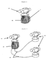
- FIG. 2 a complete cupola carrying by way of illustration a double-barreled weapon.
- This cupola is built by assembling, in configuration close, a head assembly 20 comprising a head cupola 16, an actuator 8 (not shown) and a pin 15 (not shown), on a hydraulic generator 22.
- the hydraulic generator is housed inside the housing cylindrical cupola.
- This illustrated figure a configuration with a single cupola consisting of a generator 22 and a head assembly 20 mounted close.
- Figure 3 illustrates another configuration with a generator 22 supplying hydraulic power, by via connecting means 23, three sets of head 20, 21.
- the figure shows by way of illustration a close head set 20 and two offset head sets 21.
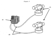
- Figure 4 illustrates another configuration with a generator 22 supplying hydraulic power, by via connecting means 23, two sets of deported head 21. It is not necessary to have a close head assembly 20 on the generator. The generator 22 can then be accommodated with more freedom.
Landscapes
- Engineering & Computer Science (AREA)
- General Engineering & Computer Science (AREA)
- Physics & Mathematics (AREA)
- Fluid Mechanics (AREA)
- Mechanical Engineering (AREA)
- Chemical & Material Sciences (AREA)
- Analytical Chemistry (AREA)
- Other Liquid Machine Or Engine Such As Wave Power Use (AREA)
- Connection Of Motors, Electrical Generators, Mechanical Devices, And The Like (AREA)
- Vending Machines For Individual Products (AREA)
- Fluid-Pressure Circuits (AREA)
Abstract
Description
- la figure 1 présente une vue d'ensemble, en perspective, d'une réalisation préférentielle du générateur électro-hydraulique objet de la présente invention,
- la figure 2 présente, en vue en perspective, un tourelleau complet emportant à titre illustratif une arme à double tube,
- la figure 3 illustre une configuration avec un ensemble de tête proche et deux ensembles de tête déportés, et
- la figure 4 illustre une configuration sans ensemble de tête proche et avec deux ensembles de tête déportés.
Claims (14)
- Générateur électro-hydraulique, comprenant un réservoir de fluide hydraulique (1) et un ensemble de composants comprenant un moteur (2) entraínant une pompe hydraulique (3), un accumulateur (4), un moyen de distribution du fluide hydraulique (5) et des moyens de liaison (9) entre ces différents composants, caractérisé en ce que le réservoir (1) et les composants (2, 3, 4, 5, 9) sont insérés dans un volume cylindrique (10) délimité par une surface circulaire (13), une première face plane d'extrémité (11) et une seconde face plane d'extrémité (12) et en ce que les composants (2, 3, 4, 5, 9) sont fixés au réservoir (1).
- Générateur selon la revendication 1, caractérisé en ce que le réservoir (1) présente une forme approximativement cylindrique limitée par une paroi circulaire (13') proche de la surface circulaire (13), une première paroi plane (11') appliquée contre la première face plane (11) et une seconde paroi plane (12').
- Générateur selon l'une quelconque des revendications 1 ou 2, caractérisé en ce qu'il comporte un échangeur (7) agencé selon la surface circulaire (13).
- Générateur selon l'une quelconque des revendications 1 à 3, caractérisé en ce qu'il comporte un filtre (6) inséré dans le volume cylindrique (10) et fixé sur le réservoir (1).
- Générateur selon l'une quelconque des revendications 1 à 4, caractérisé en ce que les composants (2, 3, 4, 5, 9) et le filtre (6) sont fixés sur la seconde paroi plane (12')
- Générateur selon l'une quelconque des revendications 1 à 5, caractérisé en ce que la pompe (3) est immergée dans le réservoir (1).
- Générateur selon l'une quelconque des revendications 1 à 6 caractérisé en ce que la seconde paroi plane (12') comporte, au droit d'au moins un des composants (2, 3, 4, 5, 9) ou du filtre (6), un décrochement axial(14).
- Générateur selon l'une quelconque des revendications 1 à 7, caractérisé en ce que le moteur (2) est un moteur électrique à courant continu basse tension.
- Générateur selon l'une quelconque des revendications 4 à 8, caractérisé en ce que le filtre (6) est en tout ou partie inséré dans le réservoir (1).
- Générateur selon l'une quelconque des revendications 1 à 9, caractérisé en ce que le réservoir (1) présente, au niveau de la paroi circulaire (13'), un décrochement radial (14') destiné à recevoir l'accumulateur (4).
- Application du générateur selon l'une quelconque des revendications 1 à 10 à la mise en mouvement d'au moins un ensemble de tête (20, 21) comprenant un actionneur (8) entraínant en rotation un axe (15) solidaire d'une tête de tourelleau (16, 17).
- Application du générateur selon la revendication 11, caractérisé en ce que l'actionneur (8) est un vérin double-effet comprenant un piston solidaire d'une crémaillère (18) entraínés en translation, ladite crémaillère engrenant sur un pignon (19) circulaire solidaire de l'axe (15).
- Application du générateur selon l'une quelconque des revendications 11 ou 12, caractérisé en ce que l'actionneur (8) est inséré dans le volume cylindrique (10), disposé selon un diamètre dudit volume cylindrique (10) et fixé sur la paroi plane (12') du réservoir (1) et en ce que l'ensemble de tête (20) est disposé au-dessus du volume cylindrique (10).
- Application du générateur selon l'une quelconque des revendications 11 à 13, caractérisé en ce qu'au moins un ensemble de tête (21) est déporté à distance du générateur (22).
Applications Claiming Priority (2)
| Application Number | Priority Date | Filing Date | Title |
|---|---|---|---|
| FR3019471 | 2003-02-18 | ||
| FR0319471 | 2003-02-18 |
Publications (2)
| Publication Number | Publication Date |
|---|---|
| EP1450047A1 true EP1450047A1 (fr) | 2004-08-25 |
| EP1450047B1 EP1450047B1 (fr) | 2006-01-04 |
Family
ID=32732073
Family Applications (1)
| Application Number | Title | Priority Date | Filing Date |
|---|---|---|---|
| EP04290322A Expired - Lifetime EP1450047B1 (fr) | 2003-02-18 | 2004-02-09 | Générateur électro-hydraulique compact pour montorisation de tourelleau |
Country Status (4)
| Country | Link |
|---|---|
| EP (1) | EP1450047B1 (fr) |
| AT (1) | ATE315178T1 (fr) |
| DE (1) | DE602004000303T2 (fr) |
| ES (1) | ES2255036T3 (fr) |
Cited By (1)
| Publication number | Priority date | Publication date | Assignee | Title |
|---|---|---|---|---|
| CN104089064A (zh) * | 2014-05-26 | 2014-10-08 | 武汉大禹阀门股份有限公司 | 一种阀门的光伏液压控制装置 |
Families Citing this family (1)
| Publication number | Priority date | Publication date | Assignee | Title |
|---|---|---|---|---|
| DE102013008407B3 (de) | 2013-05-16 | 2014-07-17 | Mbda Deutschland Gmbh | Vorratsmodul zum Versorgen eines Wirksystems sowie Wirksystem mit Vorratsmodul |
Citations (15)
| Publication number | Priority date | Publication date | Assignee | Title |
|---|---|---|---|---|
| US2528645A (en) * | 1945-06-22 | 1950-11-07 | Massachusetts Inst Technology | Hydraulic power transmission apparatus |
| US3223000A (en) * | 1964-05-27 | 1965-12-14 | James A Payne | Gun control |
| JPS4989074A (fr) * | 1972-12-29 | 1974-08-26 | ||
| GB1429795A (en) * | 1972-03-23 | 1976-03-24 | Rotork Ltd | Pressure equalising arrangements |
| US3979909A (en) * | 1976-01-12 | 1976-09-14 | Hydrapower Inc. | Hydraulic actuator |
| US5104294A (en) * | 1990-06-14 | 1992-04-14 | Kabushiki Kaisha Showa Seisakusho | Hydraulic pump assembly with accumulator and oil reservoir |
| US5253982A (en) * | 1992-11-23 | 1993-10-19 | Vickers, Incorporated | Electrohydraulic pump load control system |
| DE4219462A1 (de) * | 1992-06-13 | 1993-12-16 | Rexroth Mannesmann Gmbh | Hydraulik-Aggregat |
| WO1995002769A1 (fr) * | 1993-07-17 | 1995-01-26 | Zf Friedrichshafen Ag | Systeme hydraulique d'alimentation en huile de dispositifs assistes |
| EP0694700A1 (fr) * | 1994-07-27 | 1996-01-31 | HUGO JUNKERS WERKE GmbH | Système hydraulique mobile |
| JPH10299645A (ja) * | 1997-04-28 | 1998-11-10 | Shimadzu Corp | 液圧ユニット |
| WO1998056630A1 (fr) * | 1997-06-13 | 1998-12-17 | Continental Teves Ag & Co. Ohg | Organe hydraulique |
| EP0916853A2 (fr) * | 1997-11-18 | 1999-05-19 | Worcester Controls Licensco | Vérin électrohydraulique |
| JP2001227501A (ja) * | 2000-02-15 | 2001-08-24 | Taiyo Ltd | 油圧供給装置 |
| DE10028957A1 (de) * | 2000-06-16 | 2002-01-03 | Lukas Hydraulik Gmbh & Co Kg | Tragbare Hydraulikpumpeneinheit |
-
2004
- 2004-02-09 ES ES04290322T patent/ES2255036T3/es not_active Expired - Lifetime
- 2004-02-09 DE DE602004000303T patent/DE602004000303T2/de not_active Expired - Lifetime
- 2004-02-09 EP EP04290322A patent/EP1450047B1/fr not_active Expired - Lifetime
- 2004-02-09 AT AT04290322T patent/ATE315178T1/de not_active IP Right Cessation
Patent Citations (15)
| Publication number | Priority date | Publication date | Assignee | Title |
|---|---|---|---|---|
| US2528645A (en) * | 1945-06-22 | 1950-11-07 | Massachusetts Inst Technology | Hydraulic power transmission apparatus |
| US3223000A (en) * | 1964-05-27 | 1965-12-14 | James A Payne | Gun control |
| GB1429795A (en) * | 1972-03-23 | 1976-03-24 | Rotork Ltd | Pressure equalising arrangements |
| JPS4989074A (fr) * | 1972-12-29 | 1974-08-26 | ||
| US3979909A (en) * | 1976-01-12 | 1976-09-14 | Hydrapower Inc. | Hydraulic actuator |
| US5104294A (en) * | 1990-06-14 | 1992-04-14 | Kabushiki Kaisha Showa Seisakusho | Hydraulic pump assembly with accumulator and oil reservoir |
| DE4219462A1 (de) * | 1992-06-13 | 1993-12-16 | Rexroth Mannesmann Gmbh | Hydraulik-Aggregat |
| US5253982A (en) * | 1992-11-23 | 1993-10-19 | Vickers, Incorporated | Electrohydraulic pump load control system |
| WO1995002769A1 (fr) * | 1993-07-17 | 1995-01-26 | Zf Friedrichshafen Ag | Systeme hydraulique d'alimentation en huile de dispositifs assistes |
| EP0694700A1 (fr) * | 1994-07-27 | 1996-01-31 | HUGO JUNKERS WERKE GmbH | Système hydraulique mobile |
| JPH10299645A (ja) * | 1997-04-28 | 1998-11-10 | Shimadzu Corp | 液圧ユニット |
| WO1998056630A1 (fr) * | 1997-06-13 | 1998-12-17 | Continental Teves Ag & Co. Ohg | Organe hydraulique |
| EP0916853A2 (fr) * | 1997-11-18 | 1999-05-19 | Worcester Controls Licensco | Vérin électrohydraulique |
| JP2001227501A (ja) * | 2000-02-15 | 2001-08-24 | Taiyo Ltd | 油圧供給装置 |
| DE10028957A1 (de) * | 2000-06-16 | 2002-01-03 | Lukas Hydraulik Gmbh & Co Kg | Tragbare Hydraulikpumpeneinheit |
Non-Patent Citations (3)
| Title |
|---|
| "CENTRALES HYDRAULIQUES: PRODUITS STANDARDS OU SYSTEMES ADAPTES ?", PROMO ENERGIE FLUIDES, PPI, PARIS, FR, no. 3, April 1999 (1999-04-01), pages 12 - 13, XP000830831, ISSN: 1286-5966 * |
| PATENT ABSTRACTS OF JAPAN vol. 1999, no. 02 26 February 1999 (1999-02-26) * |
| PATENT ABSTRACTS OF JAPAN vol. 2000, no. 25 12 April 2001 (2001-04-12) * |
Cited By (1)
| Publication number | Priority date | Publication date | Assignee | Title |
|---|---|---|---|---|
| CN104089064A (zh) * | 2014-05-26 | 2014-10-08 | 武汉大禹阀门股份有限公司 | 一种阀门的光伏液压控制装置 |
Also Published As
| Publication number | Publication date |
|---|---|
| DE602004000303T2 (de) | 2006-07-06 |
| ES2255036T3 (es) | 2006-06-16 |
| ATE315178T1 (de) | 2006-02-15 |
| EP1450047B1 (fr) | 2006-01-04 |
| DE602004000303D1 (de) | 2006-03-30 |
Similar Documents
| Publication | Publication Date | Title |
|---|---|---|
| EP2376770B1 (fr) | Moteur hydraulique a pistons radiaux et commande par cylindre. | |
| EP0407436B1 (fr) | Groupe motopropulseur, notamment pour vehicule automobile et vehicule comportant un tel groupe | |
| FR2871205A1 (fr) | Element de transmission a embrayages humides pour chaine de traction de vehicule automobile, et vehicule automobile equipe d'un tel element | |
| EP2041454A2 (fr) | Circuit hydraulique de recuperation d'energie | |
| WO2002001080A1 (fr) | Systeme d'actionnement hydraulique a commande electrique | |
| FR2491559A1 (fr) | ||
| EP2376769B1 (fr) | Circuit de transmission hydraulique | |
| EP3303825A1 (fr) | Dispositif et procede de conversion d'energie et de stockage d'energie d'origine electrique, sous forme d'air comprime. | |
| FR2780450A1 (fr) | Moteur hydraulique compact | |
| FR2677409A1 (fr) | Circuit hydraulique d'alimentation d'au moins un moteur hydraulique a pistons "debrayables". | |
| FR2794818A1 (fr) | Installation hydraulique | |
| FR2851306A1 (fr) | Generateur electro-hydraulique compact pour motorisation de tourelleau | |
| FR2821393A1 (fr) | Actionneur compense a puissance optimisee | |
| EP1450047B1 (fr) | Générateur électro-hydraulique compact pour montorisation de tourelleau | |
| FR2693154A1 (fr) | Ensemble d'un organe de déplacement moteur et du dispositif de son montage à pivotement. | |
| WO2008037893A2 (fr) | Dispositif de transformation d'un mouvement linéaire en un mouvement de rotation de façon réglable | |
| EP3542058B1 (fr) | Dispositif de lubrification sous vide pour volant d'inertie | |
| EP0526333B1 (fr) | Mécanisme à fluide sous pression muni d'enceintes d'équilibrage particulières | |
| WO2013188932A2 (fr) | Système de distribution directe pour moteur a combustion interne | |
| EP3824205B1 (fr) | Circuit d'assistance hydraulique comprenant des moyens de gavage ameliores | |
| FR2709453A1 (fr) | Chaine de propulsion hydraulique optimiste pour véhicule électrique autonome actionné par batterie. | |
| EP1945921A2 (fr) | Procede de protection par ajout ponctuel d'un additif, et machine mecanique ainsi protegee | |
| FR3149625A1 (fr) | Architecture améliorée de pelle électrohydraulique | |
| FR3008752A1 (fr) | Verin pour un actionneur | |
| FR3094059A1 (fr) | Ensemble hydromécanique d’amplification de puissance |
Legal Events
| Date | Code | Title | Description |
|---|---|---|---|
| PUAI | Public reference made under article 153(3) epc to a published international application that has entered the european phase |
Free format text: ORIGINAL CODE: 0009012 |
|
| AK | Designated contracting states |
Kind code of ref document: A1 Designated state(s): AT BE BG CH CY CZ DE DK EE ES FI FR GB GR HU IE IT LI LU MC NL PT RO SE SI SK TR |
|
| AX | Request for extension of the european patent |
Extension state: AL LT LV MK |
|
| 17P | Request for examination filed |
Effective date: 20041012 |
|
| 17Q | First examination report despatched |
Effective date: 20050119 |
|
| AKX | Designation fees paid |
Designated state(s): AT BE BG CH CY CZ DE DK EE ES FI FR GB GR HU IE IT LI LU MC NL PT RO SE SI SK TR |
|
| GRAP | Despatch of communication of intention to grant a patent |
Free format text: ORIGINAL CODE: EPIDOSNIGR1 |
|
| GRAS | Grant fee paid |
Free format text: ORIGINAL CODE: EPIDOSNIGR3 |
|
| GRAA | (expected) grant |
Free format text: ORIGINAL CODE: 0009210 |
|
| AK | Designated contracting states |
Kind code of ref document: B1 Designated state(s): AT BE BG CH CY CZ DE DK EE ES FI FR GB GR HU IE IT LI LU MC NL PT RO SE SI SK TR |
|
| PG25 | Lapsed in a contracting state [announced via postgrant information from national office to epo] |
Ref country code: SK Free format text: LAPSE BECAUSE OF FAILURE TO SUBMIT A TRANSLATION OF THE DESCRIPTION OR TO PAY THE FEE WITHIN THE PRESCRIBED TIME-LIMIT Effective date: 20060104 Ref country code: SI Free format text: LAPSE BECAUSE OF FAILURE TO SUBMIT A TRANSLATION OF THE DESCRIPTION OR TO PAY THE FEE WITHIN THE PRESCRIBED TIME-LIMIT Effective date: 20060104 Ref country code: RO Free format text: LAPSE BECAUSE OF FAILURE TO SUBMIT A TRANSLATION OF THE DESCRIPTION OR TO PAY THE FEE WITHIN THE PRESCRIBED TIME-LIMIT Effective date: 20060104 Ref country code: NL Free format text: LAPSE BECAUSE OF FAILURE TO SUBMIT A TRANSLATION OF THE DESCRIPTION OR TO PAY THE FEE WITHIN THE PRESCRIBED TIME-LIMIT Effective date: 20060104 Ref country code: IE Free format text: LAPSE BECAUSE OF FAILURE TO SUBMIT A TRANSLATION OF THE DESCRIPTION OR TO PAY THE FEE WITHIN THE PRESCRIBED TIME-LIMIT Effective date: 20060104 Ref country code: FI Free format text: LAPSE BECAUSE OF FAILURE TO SUBMIT A TRANSLATION OF THE DESCRIPTION OR TO PAY THE FEE WITHIN THE PRESCRIBED TIME-LIMIT Effective date: 20060104 Ref country code: AT Free format text: LAPSE BECAUSE OF FAILURE TO SUBMIT A TRANSLATION OF THE DESCRIPTION OR TO PAY THE FEE WITHIN THE PRESCRIBED TIME-LIMIT Effective date: 20060104 |
|
| REG | Reference to a national code |
Ref country code: GB Ref legal event code: FG4D Free format text: NOT ENGLISH |
|
| REG | Reference to a national code |
Ref country code: CH Ref legal event code: EP |
|
| GBT | Gb: translation of ep patent filed (gb section 77(6)(a)/1977) |
Effective date: 20060104 |
|
| REG | Reference to a national code |
Ref country code: IE Ref legal event code: FG4D Free format text: LANGUAGE OF EP DOCUMENT: FRENCH |
|
| PG25 | Lapsed in a contracting state [announced via postgrant information from national office to epo] |
Ref country code: MC Free format text: LAPSE BECAUSE OF NON-PAYMENT OF DUE FEES Effective date: 20060228 Ref country code: BE Free format text: LAPSE BECAUSE OF NON-PAYMENT OF DUE FEES Effective date: 20060228 |
|
| PG25 | Lapsed in a contracting state [announced via postgrant information from national office to epo] |
Ref country code: LU Free format text: LAPSE BECAUSE OF NON-PAYMENT OF DUE FEES Effective date: 20060304 |
|
| REF | Corresponds to: |
Ref document number: 602004000303 Country of ref document: DE Date of ref document: 20060330 Kind code of ref document: P |
|
| PG25 | Lapsed in a contracting state [announced via postgrant information from national office to epo] |
Ref country code: DK Free format text: LAPSE BECAUSE OF FAILURE TO SUBMIT A TRANSLATION OF THE DESCRIPTION OR TO PAY THE FEE WITHIN THE PRESCRIBED TIME-LIMIT Effective date: 20060404 Ref country code: BG Free format text: LAPSE BECAUSE OF FAILURE TO SUBMIT A TRANSLATION OF THE DESCRIPTION OR TO PAY THE FEE WITHIN THE PRESCRIBED TIME-LIMIT Effective date: 20060404 Ref country code: SE Free format text: LAPSE BECAUSE OF FAILURE TO SUBMIT A TRANSLATION OF THE DESCRIPTION OR TO PAY THE FEE WITHIN THE PRESCRIBED TIME-LIMIT Effective date: 20060404 |
|
| PG25 | Lapsed in a contracting state [announced via postgrant information from national office to epo] |
Ref country code: PT Free format text: LAPSE BECAUSE OF FAILURE TO SUBMIT A TRANSLATION OF THE DESCRIPTION OR TO PAY THE FEE WITHIN THE PRESCRIBED TIME-LIMIT Effective date: 20060605 |
|
| REG | Reference to a national code |
Ref country code: ES Ref legal event code: FG2A Ref document number: 2255036 Country of ref document: ES Kind code of ref document: T3 |
|
| NLV1 | Nl: lapsed or annulled due to failure to fulfill the requirements of art. 29p and 29m of the patents act | ||
| REG | Reference to a national code |
Ref country code: IE Ref legal event code: FD4D |
|
| PLBE | No opposition filed within time limit |
Free format text: ORIGINAL CODE: 0009261 |
|
| STAA | Information on the status of an ep patent application or granted ep patent |
Free format text: STATUS: NO OPPOSITION FILED WITHIN TIME LIMIT |
|
| 26N | No opposition filed |
Effective date: 20061005 |
|
| PGFP | Annual fee paid to national office [announced via postgrant information from national office to epo] |
Ref country code: ES Payment date: 20070209 Year of fee payment: 4 |
|
| PGFP | Annual fee paid to national office [announced via postgrant information from national office to epo] |
Ref country code: TR Payment date: 20070201 Year of fee payment: 4 |
|
| BERE | Be: lapsed |
Owner name: GIAT INDUSTRIES Effective date: 20060228 |
|
| PG25 | Lapsed in a contracting state [announced via postgrant information from national office to epo] |
Ref country code: GR Free format text: LAPSE BECAUSE OF FAILURE TO SUBMIT A TRANSLATION OF THE DESCRIPTION OR TO PAY THE FEE WITHIN THE PRESCRIBED TIME-LIMIT Effective date: 20060405 Ref country code: CZ Free format text: LAPSE BECAUSE OF FAILURE TO SUBMIT A TRANSLATION OF THE DESCRIPTION OR TO PAY THE FEE WITHIN THE PRESCRIBED TIME-LIMIT Effective date: 20060104 |
|
| PG25 | Lapsed in a contracting state [announced via postgrant information from national office to epo] |
Ref country code: EE Free format text: LAPSE BECAUSE OF FAILURE TO SUBMIT A TRANSLATION OF THE DESCRIPTION OR TO PAY THE FEE WITHIN THE PRESCRIBED TIME-LIMIT Effective date: 20060104 |
|
| PG25 | Lapsed in a contracting state [announced via postgrant information from national office to epo] |
Ref country code: HU Free format text: LAPSE BECAUSE OF FAILURE TO SUBMIT A TRANSLATION OF THE DESCRIPTION OR TO PAY THE FEE WITHIN THE PRESCRIBED TIME-LIMIT Effective date: 20060705 |
|
| REG | Reference to a national code |
Ref country code: CH Ref legal event code: PL |
|
| PG25 | Lapsed in a contracting state [announced via postgrant information from national office to epo] |
Ref country code: CH Free format text: LAPSE BECAUSE OF NON-PAYMENT OF DUE FEES Effective date: 20080229 Ref country code: LI Free format text: LAPSE BECAUSE OF NON-PAYMENT OF DUE FEES Effective date: 20080229 |
|
| PG25 | Lapsed in a contracting state [announced via postgrant information from national office to epo] |
Ref country code: CY Free format text: LAPSE BECAUSE OF FAILURE TO SUBMIT A TRANSLATION OF THE DESCRIPTION OR TO PAY THE FEE WITHIN THE PRESCRIBED TIME-LIMIT Effective date: 20060104 |
|
| REG | Reference to a national code |
Ref country code: ES Ref legal event code: FD2A Effective date: 20080211 |
|
| REG | Reference to a national code |
Ref country code: GB Ref legal event code: 732E Free format text: REGISTERED BETWEEN 20090625 AND 20090701 |
|
| PG25 | Lapsed in a contracting state [announced via postgrant information from national office to epo] |
Ref country code: ES Free format text: LAPSE BECAUSE OF NON-PAYMENT OF DUE FEES Effective date: 20080211 |
|
| PGFP | Annual fee paid to national office [announced via postgrant information from national office to epo] |
Ref country code: IT Payment date: 20090210 Year of fee payment: 6 |
|
| PG25 | Lapsed in a contracting state [announced via postgrant information from national office to epo] |
Ref country code: IT Free format text: LAPSE BECAUSE OF NON-PAYMENT OF DUE FEES Effective date: 20100209 |
|
| PGFP | Annual fee paid to national office [announced via postgrant information from national office to epo] |
Ref country code: FR Payment date: 20110310 Year of fee payment: 8 Ref country code: DE Payment date: 20110207 Year of fee payment: 8 |
|
| PGFP | Annual fee paid to national office [announced via postgrant information from national office to epo] |
Ref country code: GB Payment date: 20110128 Year of fee payment: 8 |
|
| PG25 | Lapsed in a contracting state [announced via postgrant information from national office to epo] |
Ref country code: TR Free format text: LAPSE BECAUSE OF NON-PAYMENT OF DUE FEES Effective date: 20100922 |
|
| GBPC | Gb: european patent ceased through non-payment of renewal fee |
Effective date: 20120209 |
|
| REG | Reference to a national code |
Ref country code: FR Ref legal event code: ST Effective date: 20121031 |
|
| REG | Reference to a national code |
Ref country code: DE Ref legal event code: R119 Ref document number: 602004000303 Country of ref document: DE Effective date: 20120901 |
|
| PG25 | Lapsed in a contracting state [announced via postgrant information from national office to epo] |
Ref country code: TR Free format text: LAPSE BECAUSE OF NON-PAYMENT OF DUE FEES Effective date: 20080209 Ref country code: GB Free format text: LAPSE BECAUSE OF NON-PAYMENT OF DUE FEES Effective date: 20120209 Ref country code: FR Free format text: LAPSE BECAUSE OF NON-PAYMENT OF DUE FEES Effective date: 20120229 |
|
| PG25 | Lapsed in a contracting state [announced via postgrant information from national office to epo] |
Ref country code: DE Free format text: LAPSE BECAUSE OF NON-PAYMENT OF DUE FEES Effective date: 20120901 |