EP1450041A1 - Refrigerant circuit with a controlled swash-plate type compressor - Google Patents
Refrigerant circuit with a controlled swash-plate type compressor Download PDFInfo
- Publication number
- EP1450041A1 EP1450041A1 EP04000690A EP04000690A EP1450041A1 EP 1450041 A1 EP1450041 A1 EP 1450041A1 EP 04000690 A EP04000690 A EP 04000690A EP 04000690 A EP04000690 A EP 04000690A EP 1450041 A1 EP1450041 A1 EP 1450041A1
- Authority
- EP
- European Patent Office
- Prior art keywords
- refrigerant
- swash plate
- pressure
- compressor
- control valve
- Prior art date
- Legal status (The legal status is an assumption and is not a legal conclusion. Google has not performed a legal analysis and makes no representation as to the accuracy of the status listed.)
- Withdrawn
Links
Images

Classifications
-
- F—MECHANICAL ENGINEERING; LIGHTING; HEATING; WEAPONS; BLASTING
- F25—REFRIGERATION OR COOLING; COMBINED HEATING AND REFRIGERATION SYSTEMS; HEAT PUMP SYSTEMS; MANUFACTURE OR STORAGE OF ICE; LIQUEFACTION SOLIDIFICATION OF GASES
- F25B—REFRIGERATION MACHINES, PLANTS OR SYSTEMS; COMBINED HEATING AND REFRIGERATION SYSTEMS; HEAT PUMP SYSTEMS
- F25B9/00—Compression machines, plants or systems, in which the refrigerant is air or other gas of low boiling point
- F25B9/002—Compression machines, plants or systems, in which the refrigerant is air or other gas of low boiling point characterised by the refrigerant
- F25B9/008—Compression machines, plants or systems, in which the refrigerant is air or other gas of low boiling point characterised by the refrigerant the refrigerant being carbon dioxide
-
- F—MECHANICAL ENGINEERING; LIGHTING; HEATING; WEAPONS; BLASTING
- F04—POSITIVE - DISPLACEMENT MACHINES FOR LIQUIDS; PUMPS FOR LIQUIDS OR ELASTIC FLUIDS
- F04B—POSITIVE-DISPLACEMENT MACHINES FOR LIQUIDS; PUMPS
- F04B27/00—Multi-cylinder pumps specially adapted for elastic fluids and characterised by number or arrangement of cylinders
- F04B27/08—Multi-cylinder pumps specially adapted for elastic fluids and characterised by number or arrangement of cylinders having cylinders coaxial with, or parallel or inclined to, main shaft axis
- F04B27/14—Control
- F04B27/16—Control of pumps with stationary cylinders
- F04B27/18—Control of pumps with stationary cylinders by varying the relative positions of a swash plate and a cylinder block
- F04B27/1804—Controlled by crankcase pressure
-
- F—MECHANICAL ENGINEERING; LIGHTING; HEATING; WEAPONS; BLASTING
- F25—REFRIGERATION OR COOLING; COMBINED HEATING AND REFRIGERATION SYSTEMS; HEAT PUMP SYSTEMS; MANUFACTURE OR STORAGE OF ICE; LIQUEFACTION SOLIDIFICATION OF GASES
- F25B—REFRIGERATION MACHINES, PLANTS OR SYSTEMS; COMBINED HEATING AND REFRIGERATION SYSTEMS; HEAT PUMP SYSTEMS
- F25B49/00—Arrangement or mounting of control or safety devices
- F25B49/02—Arrangement or mounting of control or safety devices for compression type machines, plants or systems
- F25B49/022—Compressor control arrangements
-
- F—MECHANICAL ENGINEERING; LIGHTING; HEATING; WEAPONS; BLASTING
- F04—POSITIVE - DISPLACEMENT MACHINES FOR LIQUIDS; PUMPS FOR LIQUIDS OR ELASTIC FLUIDS
- F04B—POSITIVE-DISPLACEMENT MACHINES FOR LIQUIDS; PUMPS
- F04B27/00—Multi-cylinder pumps specially adapted for elastic fluids and characterised by number or arrangement of cylinders
- F04B27/08—Multi-cylinder pumps specially adapted for elastic fluids and characterised by number or arrangement of cylinders having cylinders coaxial with, or parallel or inclined to, main shaft axis
- F04B27/14—Control
- F04B27/16—Control of pumps with stationary cylinders
- F04B27/18—Control of pumps with stationary cylinders by varying the relative positions of a swash plate and a cylinder block
- F04B27/1804—Controlled by crankcase pressure
- F04B2027/184—Valve controlling parameter
- F04B2027/1854—External parameters
-
- F—MECHANICAL ENGINEERING; LIGHTING; HEATING; WEAPONS; BLASTING
- F25—REFRIGERATION OR COOLING; COMBINED HEATING AND REFRIGERATION SYSTEMS; HEAT PUMP SYSTEMS; MANUFACTURE OR STORAGE OF ICE; LIQUEFACTION SOLIDIFICATION OF GASES
- F25B—REFRIGERATION MACHINES, PLANTS OR SYSTEMS; COMBINED HEATING AND REFRIGERATION SYSTEMS; HEAT PUMP SYSTEMS
- F25B2309/00—Gas cycle refrigeration machines
- F25B2309/06—Compression machines, plants or systems characterised by the refrigerant being carbon dioxide
- F25B2309/061—Compression machines, plants or systems characterised by the refrigerant being carbon dioxide with cycle highest pressure above the supercritical pressure
-
- F—MECHANICAL ENGINEERING; LIGHTING; HEATING; WEAPONS; BLASTING
- F25—REFRIGERATION OR COOLING; COMBINED HEATING AND REFRIGERATION SYSTEMS; HEAT PUMP SYSTEMS; MANUFACTURE OR STORAGE OF ICE; LIQUEFACTION SOLIDIFICATION OF GASES
- F25B—REFRIGERATION MACHINES, PLANTS OR SYSTEMS; COMBINED HEATING AND REFRIGERATION SYSTEMS; HEAT PUMP SYSTEMS
- F25B2600/00—Control issues
- F25B2600/02—Compressor control
- F25B2600/023—Compressor control controlling swash plate angles
-
- F—MECHANICAL ENGINEERING; LIGHTING; HEATING; WEAPONS; BLASTING
- F25—REFRIGERATION OR COOLING; COMBINED HEATING AND REFRIGERATION SYSTEMS; HEAT PUMP SYSTEMS; MANUFACTURE OR STORAGE OF ICE; LIQUEFACTION SOLIDIFICATION OF GASES
- F25B—REFRIGERATION MACHINES, PLANTS OR SYSTEMS; COMBINED HEATING AND REFRIGERATION SYSTEMS; HEAT PUMP SYSTEMS
- F25B2700/00—Sensing or detecting of parameters; Sensors therefor
- F25B2700/19—Pressures
- F25B2700/193—Pressures of the compressor
- F25B2700/1933—Suction pressures
-
- F—MECHANICAL ENGINEERING; LIGHTING; HEATING; WEAPONS; BLASTING
- F25—REFRIGERATION OR COOLING; COMBINED HEATING AND REFRIGERATION SYSTEMS; HEAT PUMP SYSTEMS; MANUFACTURE OR STORAGE OF ICE; LIQUEFACTION SOLIDIFICATION OF GASES
- F25B—REFRIGERATION MACHINES, PLANTS OR SYSTEMS; COMBINED HEATING AND REFRIGERATION SYSTEMS; HEAT PUMP SYSTEMS
- F25B2700/00—Sensing or detecting of parameters; Sensors therefor
- F25B2700/21—Temperatures
- F25B2700/2117—Temperatures of an evaporator
- F25B2700/21174—Temperatures of an evaporator of the refrigerant at the inlet of the evaporator
-
- F—MECHANICAL ENGINEERING; LIGHTING; HEATING; WEAPONS; BLASTING
- F25—REFRIGERATION OR COOLING; COMBINED HEATING AND REFRIGERATION SYSTEMS; HEAT PUMP SYSTEMS; MANUFACTURE OR STORAGE OF ICE; LIQUEFACTION SOLIDIFICATION OF GASES
- F25B—REFRIGERATION MACHINES, PLANTS OR SYSTEMS; COMBINED HEATING AND REFRIGERATION SYSTEMS; HEAT PUMP SYSTEMS
- F25B40/00—Subcoolers, desuperheaters or superheaters
Definitions
- the invention relates to a refrigerant circuit with a regulated swash plate compressor, in particular for a motor vehicle air conditioning system operated with the refrigerant R744 (CO 2 refrigerant).
- the air that is supplied to the passenger compartment is at one Heat exchanger (evaporator) cooled, the refrigerant conducted in it evaporates and extracts the required amount of heat from the air flowing past.
- the refrigerant is conditioned by changes in state, so that a limited amount of refrigerant is sufficient to cool the air.
- the gas cooler or condenser refrigerant condenser
- the amount of heat supplied to the evaporator by the outside air withdrawn again for which purpose between the refrigerant and the outside air Temperature difference must prevail.
- the gaseous refrigerant is in one Compressor compresses and increases in temperature before it enters the gas cooler is directed and liquefied there. Between the evaporator and the gas cooler is the further arranged an expansion device to the compressed in the compressor and thus refrigerants provided with a higher pressure and a higher temperature to relax again and to regulate the refrigerant flow.
- Compressor and Expansion valves separate the refrigerant circuit into a high pressure and one Low pressure area.
- Swashplate compressors are usually used in motor vehicle air conditioning systems (Compressors) used.
- Compressor is a rotary movement which is arranged in a crankcase Swashplate over connecting elements or coupling links in a back and forth Moving movement implemented by pistons movably arranged in cylinders.
- gaseous refrigerant drawn in from a suction chamber is compressed and discharged through an exhaust chamber.
- the stroke of the pistons changes to Agreement with changes in the swash plate inclination angle.
- This Tilt angle is controlled in a known manner by regulating the pressure in the Crank chamber in which the swash plate is arranged, with reference to the intake pressure set in the cylinder, this pressure by a housed in the cylinder block Control valve is regulated.
- the swash plate inclination changed to the delivery capacity of the compressor to the required cooling capacity adapt.
- this is through a control spring in the direction of reducing its inclination, i.e. in the direction a reduction in the stroke volume, preloaded.
- the proposed refrigerant circuit consists of a swash plate compressor (Compressor), at the outlet of which a high pressure section with a gas cooler or Refrigerant condenser and on its suction side (compressor inlet) Low pressure section are connected to an evaporator, and the High pressure section with adjustable connecting the low pressure section Expansion device, which are connected to each other by a refrigerant line, and a control valve on the suction side of the compressor, through which the refrigerant is sucked back into this, being in front of the inlet of the evaporator Temperature sensor or a pressure sensor in the suction line in front of the compressor is arranged, the control electronics with the actuator of the control valve in There is an operative connection, and that the tilt-adjustable swash plate, the control valve and the respective sensor form a suction pressure control circuit.
- Compressor swash plate compressor
- the control valve is a 3-way valve with a suction pressure, a high pressure and a Crank chamber connection.
- the temperature sensor measures the saturation temperature at Evaporator input from which is stored in a control electronics Vapor pressure curve of the respective refrigerant, the evaporator pressure and thus also the Suction pressure is determined. This eliminates the need for complicated and time-consuming regulation several sensors. Instead of a pressure sensor in the suction line, the Compressor a temperature sensor used in front of the evaporator inlet, because of this is cheaper.
- the control strategy provides that the suction pressure is independent of keep the speed of the compressor constant. This means that the piston stroke at high engine and thus compressor speeds are low and at maximum when idling.
- the refrigerant circuit controlled in this way enables rapid adjustment of the Compressor output for the respective cooling requirement.
- the control valve is preferably a 3-way valve with a pulse width modulation electromagnetic actuator that has a short response time.
- An internal heat exchanger with the suction line of the compressor can be formed in the outlet line of the refrigerant condenser, through which the high-pressure cooled refrigerant is led to the expansion element and the expanded and vaporous refrigerant is led to the compressor, so that the refrigerant to be expanded and evaporated is cooled , with the consequence that the liquid portion of the refrigerant increases after the expansion and thus more liquid refrigerant is available.
- the internal heat exchanger thus increases the cooling capacity and also the efficiency of the cooling circuit.
- An internal heat exchanger is also advantageous because of the rapid change in operating conditions. This version with an internal heat exchanger is particularly suitable for CO 2 refrigerants.
- a thematic expansion valve is advantageously used as the expansion organ used.
- overheating is on Evaporator outlet increased so that the expansion valve opens wide and the Refrigerant mass flow is increased, making the maximum in the shortest possible time Cooling capacity is achieved.
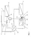
- This refrigerant circuit has a swash plate compressor 1, a gas cooler (refrigerant condenser) 2, an inner heat exchanger 3 with a first refrigerant line coil 3.1, a thermostatic expansion valve 4 of known type with a thermostatic sensor 5, an evaporator 6, at the outlet of which the sensor 5 is arranged, a liquid collector 7 and the heat exchanger 3 with a second refrigerant line coil 3.2 in front of the compressor 1.
- a 3-way control valve 8 is arranged in the valve cover on the suction side of the compressor 1, via which the refrigerant is sucked into the latter.
- This control valve 8 has a connection 8.1 to the suction chamber of the compressor 1, a connection 8.2 to its high pressure chamber, a connection 8.3 to its crank chamber and an electromagnetic actuator 8.4 (not shown further), which is operatively connected to these connections 8.1 to 8.3.
- the actuator 8.4 is connected to control electronics 9, in which the CO 2 vapor pressure curve is stored and which receives as an input variable the saturation temperature of the refrigerant at the inlet of the evaporator 6 from a temperature sensor 10 arranged there.
- the CO 2 refrigerant which has a pressure of approximately 35 to 45 bar and a temperature of approximately 20 ° C. on the suction side of the compressor 1, is compressed in the compressor 1 to a pressure of essentially 110 bar, the temperature of the Refrigerant rises to approx. 100 ° C.
- the gas cooler 2 the refrigerant is cooled to approx. 55 ° to 60 ° C by the outside air flowing past and liquefied in the process.
- the heat extracted from the CO 2 refrigerant is dissipated with the outside air.
- the CO 2 refrigerant flowing through the line coil 3.1 gives heat to the one flowing through the line coil 3.2
- Refrigerant from which is integrated in the suction line of the compressor, wherein it is cooled to a temperature of substantially 25 ° C.
- the liquid CO 2 refrigerant which has a pressure of about 110 bar and a temperature of essentially 25 ° C. on the high pressure side, is converted into the wet vapor state, where it is expanded and released to a pressure of 35 to 45 bar a temperature of 0 ° to 10 ° C is cooled.
- the CO 2 refrigerant enters the evaporator 6, where it evaporates by absorbing heat from the outside or recirculated air to be cooled for the passenger compartment at a constant pressure of 35 to 45 bar, which corresponds to the suction pressure at the compressor 1.
- the expansion valve 4 as an adjustable mass flow valve is set so that the refrigerant mass flow passing through the expansion valve 4 for cooling the air is set so that the refrigerant in the evaporator 6 is converted as completely as possible into the gaseous state and at the evaporator outlet by about 2 ° to 4 ° C is overheated.
- the gaseous refrigerant then flows through the liquid collector 7 in order to retain residues of liquid refrigerant.
- Saturated wet CO 2 is present at the evaporator inlet, the saturation temperature of which depends on the output of the compressor 1. If the compressor 1 generates a high CO 2 mass flow and a greater cooling capacity than the target cooling capacity due to a high speed of the vehicle engine with which it is coupled, the saturation temperature at the evaporator inlet and thus also the saturation pressure drop. In order to reduce the mass flow and thus the cooling capacity of the compressor 1, the piston stroke in this must be reduced. This is done with the help of the central control electronics 9 and the pulse-width-modulated control valve 8, which is coupled to the central control electronics 9, which receives the saturation temperature of the CO refrigerant from the temperature sensor 10.
- the suction pressure in the compressor 1 is kept essentially constant, regardless of the speed of the compressor, via the control valve 8.
- the inclination of the swash plate in this must be reduced. This is done by changing the pressure difference between the pressure in the crank chamber and the pressure in the suction chamber of the compressor 1. Consequently, with the pressure in the suction chamber remaining constant, the pressure in the crank chamber must be increased in order to reduce the inclination of the swash plate and the piston stroke.
- the actuator 8.4 of the control valve 8 is adjusted by the control electronics 9 so that gaseous CO 2 refrigerant is pressed into the crank chamber of the compressor 1 from the high-pressure chamber connection 8.2.
Abstract
Description
Die Erfindung betrifft einen Kältemittelkreislauf mit einem geregelten Taumelscheibenkompressor, insbesondere für eine mit dem Kältemittel R744 (CO2-Kältemittel) betriebene Kfz-Klimaanlage.The invention relates to a refrigerant circuit with a regulated swash plate compressor, in particular for a motor vehicle air conditioning system operated with the refrigerant R744 (CO 2 refrigerant).
In Kfz-Klimaanlagen wird die Luft, die der Fahrgastzelle zugeführt wird, an einem Wärmetauscher (Verdampfer) gekühlt, wobei das in diesen geleitete Kältemittel verdampft und die dafür erforderliche Wärmemenge der vorbeiströmenden Luft entzieht. In einem Kreisprozeß wird das Kältemittel durch Zustandsänderungen aufbereitet, so daß für das Kühlen der Luft eine begrenzte Kältemittelmenge ausreicht. In einem zweiten Wärmetauscher, dem Gaskühler oder Kondensator (Kältemittelverflüssiger), wird dem Kältemittel die im Verdampfer zugeführte Wärmemenge durch Außenluft wieder entzogen, wozu zwischen dem Kältemittel und der Außenluft eine Temperaturdifferenz herrschen muß. Daher wird das gasförmige Kältemittel in einem Kompressor verdichtet und in seiner Temperatur erhöht, bevor es in den Gaskühler geleitet und dort verflüssigt wird. Zwischen dem Verdampfer und dem Gaskühler ist des weiteren ein Expansionsorgan angeordnet, um das im Kompressor verdichtete und somit mit einem höheren Druck und mit einer höheren Temperatur versehene Kältemittel wieder zu entspannen und um den Kältemittelfluß zu regeln. Kompressor und Expansionsventil trennen den Kältemittelkreislauf in einen Hochdruck- und einen Niederdruckbereich. Üblicherweise befindet sich im Hochdruckbereich, also im Bereich des verdichteten Kältemittels zwischen dem Kompressor und dem Expansionsorgan auch ein Kältemittelsammler, in dem das stark hygroskopische Kältemittel getrocknet wird, um Korrossionsschäden im Verdichter zu vermeiden.In automotive air conditioning systems, the air that is supplied to the passenger compartment is at one Heat exchanger (evaporator) cooled, the refrigerant conducted in it evaporates and extracts the required amount of heat from the air flowing past. In a cyclic process, the refrigerant is conditioned by changes in state, so that a limited amount of refrigerant is sufficient to cool the air. In one second heat exchanger, the gas cooler or condenser (refrigerant condenser), the amount of heat supplied to the evaporator by the outside air withdrawn again, for which purpose between the refrigerant and the outside air Temperature difference must prevail. Therefore, the gaseous refrigerant is in one Compressor compresses and increases in temperature before it enters the gas cooler is directed and liquefied there. Between the evaporator and the gas cooler is the further arranged an expansion device to the compressed in the compressor and thus refrigerants provided with a higher pressure and a higher temperature to relax again and to regulate the refrigerant flow. Compressor and Expansion valves separate the refrigerant circuit into a high pressure and one Low pressure area. Usually located in the high pressure area, i.e. in the area of the compressed refrigerant between the compressor and the expansion device also a refrigerant collector in which the highly hygroscopic refrigerant is dried to avoid corrosion damage in the compressor.
In Kraftfahrzeug-Klimaanlagen werden in der Regel Taumelscheibenkompressoren (Kompressoren) eingesetzt. Bei einem in der DE 41 39186 A1 beschriebenen Kompressor wird eine Drehbewegung der in einem Kurbelgehäuse angeordneten Taumelscheibe über Verbindungselemente oder Kupplungsglieder in eine hin- und hergehende Bewegung von in Zylindern bewegbar angeordneten Kolben umgesetzt. In diesen wird aus einer Ansaugkammer angesaugtes gasförmiges Kältemittel komprimiert und durch eine Ausstoßkammer ausgefördert. Der Hub der Kolben ändert sich in Übereinstimmung mit Änderungen im Neigungswinkel der Taumelscheibe. Dieser Neigungswinkel wird in bekannter Weise durch eine Regelung des Druckes in der Kurbelkammer, in der die Taumelscheibe angeordnet ist, mit Bezug zum Ansaugdruck im Zylinder eingestellt, wobei dieser Druck durch ein im Zylinderblock untergebrachtes Regelventil geregelt wird. Als Ergebnis dessen wird die Neigung der Taumelscheibe geändert, um die Förderleistung des Kompressors an die geforderte Kälteleistung anzupassen. Zur Stabilisierung der Neigungsstellung der Taumelscheibe ist diese durch eine Regelfeder in Richtung der Reduzierung ihrer Schrägstellung, also in Richtung einer Verkleinerung des Hubvolumens, vorgespannt.Swashplate compressors are usually used in motor vehicle air conditioning systems (Compressors) used. In one described in DE 41 39186 A1 Compressor is a rotary movement which is arranged in a crankcase Swashplate over connecting elements or coupling links in a back and forth Moving movement implemented by pistons movably arranged in cylinders. In gaseous refrigerant drawn in from a suction chamber is compressed and discharged through an exhaust chamber. The stroke of the pistons changes to Agreement with changes in the swash plate inclination angle. This Tilt angle is controlled in a known manner by regulating the pressure in the Crank chamber in which the swash plate is arranged, with reference to the intake pressure set in the cylinder, this pressure by a housed in the cylinder block Control valve is regulated. As a result, the swash plate inclination changed to the delivery capacity of the compressor to the required cooling capacity adapt. To stabilize the inclination of the swash plate, this is through a control spring in the direction of reducing its inclination, i.e. in the direction a reduction in the stroke volume, preloaded.
Wegen der schnellen Änderung der Betriebsbedingungen infolge der Fahrzeugbewegung mit wechselnden Fahrgeschwindigkeiten und unterschiedlichem Wärmeeinfall unterliegt der Kältebedarf großen Schwankungen, an den sich die Kälteleistung des Kompressors anpassen muß. In der CH 690 189 A5 ist ein Regelverfahren beschrieben, bei dem der Kältemittelkreislauf in Strömungsrichtung hinter dem Expansionsventil und dem sich hinter diesem anschließenden Wärmeaustauscher mit dem Triebraum (Kurbelkammer) des Kompressors verbunden ist, so daß in diesem mindestens angenähert derselbe Druck wie an dieser Verbindungsstelle vorhanden ist. Die Leistungsregelung erfolgt dabei durch ein Regelventil, daß in Strömungsrichtung hinter dieser Verbindungsstelle und an der Saugseite des Kompressors angeordnet ist, so daß die Verstellung der Neigung der Taumelscheibe durch die geregelte Differenz zwischen dem Druck in der Kurbelkammer und demjenigen an der Saugseite erfolgt.Because of the rapid change in operating conditions as a result of Vehicle movement with changing driving speeds and different Incidence of heat is subject to large fluctuations in the cooling demand, to which the The cooling capacity of the compressor must be adjusted. In CH 690 189 A5 there is a Control method described in which the refrigerant circuit in the flow direction behind the expansion valve and the one behind it Heat exchanger connected to the drive chamber (crank chamber) of the compressor is, so that in this at least approximately the same pressure as on this Connection point is present. The power is regulated by a Control valve that in the flow direction behind this connection point and at the Suction side of the compressor is arranged so that the adjustment of the inclination of the Swashplate by the regulated difference between the pressure in the crank chamber and the one on the suction side.
Es ist Aufgabe der Erfindung, einen Kältemittelkreislauf mit einem geregelten Taumelscheibenkompressor nach dem Oberbegriff des Anspruchs 1 alternativ und auf einfache Weise zu regeln.It is an object of the invention to provide a refrigerant circuit with a regulated Swash plate compressor according to the preamble of claim 1 alternatively and easy way to regulate.
Diese Aufgabe wird bei einem Kältemittelkreislauf nach dem Oberbegriff des
Anspruchs 1 durch dessen kennzeichnende Merkmale und ein Verfahren mit den
Merkmalen des Anspruchs 7 gelöst.This task is carried out in a refrigerant circuit according to the generic term of
Claim 1 by its characterizing features and a method with the
Features of
Der vorgeschlagene Kältemittelkreislauf besteht aus einem Taumelscheibenkompressor (Kompressor), an dessen Ausgang ein Hochdruckabschnitt mit einem Gaskühler oder Kältemittelverflüssiger und an dessen Saugseite (Kompressoreingang) ein Niederdruckabschnitt mit einem Verdampfer angeschlossen sind, und einem den Hochdruckabschnitt mit dem Niederdruckabschnitt verbindenden regelbaren Expansionsorgan, die jeweils durch eine Kältemittelleitung miteinander verbunden sind, sowie einem Regelventil an der Saugseite des Kompressors, über das das Kältemittel wieder in diesen gesaugt wird, wobei vor dem Eingang des Verdampfers ein Temperatursensor oder in der Saugleitung vor dem Kompressor ein Drucksensor angeordnet ist, der über eine Regelelektronik mit dem Stellantrieb des Regelventils in Wirkverbindung steht, und daß die neigungsverstellbare Taumelscheibe, das Regelventil und der jeweilige Sensor einen Saugdruckregelkreis ausbilden. Das Regelventil ist ein 3-Wege-Ventil mit einem Saugdruck-, einem Hochdruck- und einem Kurbelkammeranschluß. Der Temperatursensor mißt dabei die Sättigungstemperatur am Verdampfereingang, aus der über die in einer Regelelektronik abgelegte Dampfdruckkurve des jeweiligen Kältemittels der Verdampferdruck und damit auch der Saugdruck bestimmt wird. Damit entfällt eine komplizierte und aufwändige Regelung mit mehreren Sensoren. Bevorzugt wird anstelle eines Drucksensors in der Saugleitung des Kompressors ein Temperatursensor vor dem Verdampfereingang eingesetzt, da dieser kostengünstiger ist. Die Regelstrategie sieht dabei vor, den Saugdruck unabhängig von der Drehzahl des Kompressors konstant zu halten. Das heißt, daß der Kolbenhub bei hohen Motor- und damit Kompressordrehzahlen klein und bei Leerlauf maximal ist. Der auf diese Weise geregelte Kältemittelkreilauf ermöglicht eine schnelle Anpassung der Kompressorleistung an die jeweilige Kälteanforderung.The proposed refrigerant circuit consists of a swash plate compressor (Compressor), at the outlet of which a high pressure section with a gas cooler or Refrigerant condenser and on its suction side (compressor inlet) Low pressure section are connected to an evaporator, and the High pressure section with adjustable connecting the low pressure section Expansion device, which are connected to each other by a refrigerant line, and a control valve on the suction side of the compressor, through which the refrigerant is sucked back into this, being in front of the inlet of the evaporator Temperature sensor or a pressure sensor in the suction line in front of the compressor is arranged, the control electronics with the actuator of the control valve in There is an operative connection, and that the tilt-adjustable swash plate, the control valve and the respective sensor form a suction pressure control circuit. The control valve is a 3-way valve with a suction pressure, a high pressure and a Crank chamber connection. The temperature sensor measures the saturation temperature at Evaporator input from which is stored in a control electronics Vapor pressure curve of the respective refrigerant, the evaporator pressure and thus also the Suction pressure is determined. This eliminates the need for complicated and time-consuming regulation several sensors. Instead of a pressure sensor in the suction line, the Compressor a temperature sensor used in front of the evaporator inlet, because of this is cheaper. The control strategy provides that the suction pressure is independent of keep the speed of the compressor constant. This means that the piston stroke at high engine and thus compressor speeds are low and at maximum when idling. The refrigerant circuit controlled in this way enables rapid adjustment of the Compressor output for the respective cooling requirement.
Das Regelventil ist bevorzugt ein pulsbreitenmoduliertes 3-Wege-Ventil mit einem elektromagnetischen Stellantrieb, der eine kurze Reaktionszeit hat.The control valve is preferably a 3-way valve with a pulse width modulation electromagnetic actuator that has a short response time.
In der Ausgangsleitung des Kältemittelverflüssigers kann ein innerer Wärmetauscher mit der Saugleitung des Kompressors gebildet sein, durch den das unter Hochdruck stehende gekühlte Kältemittel zum Expansionsorgan und das entspannte und dampfförmige Kältemittel zum Kompressor geleitet werden, so daß eine Abkühlung des zu entspannenden und zu verdampfenden Kältemittels erfolgt, mit der Konsequenz, daß der Flüssigkeitsanteil des Kältemittels nach der Expansion steigt und somit mehr flüssiges Kältemittel zur Verfügung steht. Der innere Wärmetauscher erhöht damit die Kälteleistung und auch die Effizienz des Kältekreislaufs. Aber auch wegen der schnellen Änderung der Betriebsbedingungen ist ein innerer Wärmetauscher vorteilhaft. Diese Ausführung mit einem inneren Wärmetauscher eignet sich insbesondere für CO2-Kältemittel.An internal heat exchanger with the suction line of the compressor can be formed in the outlet line of the refrigerant condenser, through which the high-pressure cooled refrigerant is led to the expansion element and the expanded and vaporous refrigerant is led to the compressor, so that the refrigerant to be expanded and evaporated is cooled , with the consequence that the liquid portion of the refrigerant increases after the expansion and thus more liquid refrigerant is available. The internal heat exchanger thus increases the cooling capacity and also the efficiency of the cooling circuit. An internal heat exchanger is also advantageous because of the rapid change in operating conditions. This version with an internal heat exchanger is particularly suitable for CO 2 refrigerants.
Als Expansionsorgan wird vorteilhafterweise ein themostatisches Expansionsventil eingesetzt. Im Anfahrzustand der Klimaanlage ist die Überhitzung am Verdampferausgang erhöht, so daß das Expansionsventil weit öffnet und der Kältemittelmassenstrom erhöht wird, wodurch in kürzester Zeit die maximale Kälteleistung erreicht wird.A thematic expansion valve is advantageously used as the expansion organ used. When the air conditioner starts up, overheating is on Evaporator outlet increased so that the expansion valve opens wide and the Refrigerant mass flow is increased, making the maximum in the shortest possible time Cooling capacity is achieved.
Die Erfindung wird nachstehend anhand eines Ausführungsbeispiels für eine insbesondere mit CO2-Kältemittel betriebene Kraftfahrzeug-Klimaanlage erläutert. Die zugehörigen Zeichnungen zeigen:
- Fig.1:
- den Kältemittelkreislauf der Klimaanlage und
- Fig. 2:
- die CO2-Dampfdruckkurve.
- Fig.1:
- the refrigerant circuit of the air conditioning system and
- Fig. 2:
- the CO 2 vapor pressure curve.
Dieser Kältemittelkreislauf weist in Kreislaufrichtung nacheinander einen
Taumelscheibenkompressor 1, einen Gaskühler (Kältemittelverflüssiger) 2, einen
inneren Wärmetauscher 3 mit einer ersten Kältemittel-Leitungsschlange 3.1, ein
thermostatisches Expansionsventil 4 bekannter Bauart mit einem thermostatischen
Sensor 5, einen Verdampfer 6, an dessen Ausgang der Sensor 5 angeordnet ist, einen
Flüssigkeitssammler 7 und den Wärmetauscher 3 mit einer zweiten Kältemittel-Leitungsschlange
3.2 vor dem Kompressor 1 auf. Im Ventildeckel an der Saugseite des
Kompressors 1 ist ein 3-Wege-Regelventil 8 angeordnet, über das das Kältemittel in
diesen gesaugt wird. Dieses Regelventil 8 weist einen Anschluß 8.1 an die Saugkammer
des Kompressors 1, einen Anschluß 8.2 an dessen Hochdruckkammer, einen
Anschluß 8.3 an dessen Kurbelkammer und ein nicht weiter dargestelltes
elektromagnetisches Stellglied 8.4 auf, das mit diesen Anschlüssen 8.1 bis 8.3 in
Wirkverbindung steht. Das Stellglied 8.4 ist an eine Regelelektronik 9 angeschlossen, in
der die CO2-Dampfdruckkurve abgelegt ist und die als Eingangsgröße die am Eingang
des Verdampfers 6 gegebene Sättigungstemperatur des Kältemittels von einem dort
angeordneten Temperatursensor 10 empfängt.This refrigerant circuit has a swash plate compressor 1, a gas cooler (refrigerant condenser) 2, an
Das CO2-Kältemittel, das auf der Saugseite des Kompressors 1 einen Druck von etwa
35 bis 45 bar und eine Temperatur von ca. 20° C aufweist, wird im Kompressor 1 auf
einen Druck von im wesentlichen 110 bar verdichtet, wobei die Temperatur des
Kältemittels auf ca. 100°C steigt. Im Gaskühler 2 wird das Kältemittel durch
vorbeiströmende Außenluft auf ca. 55° bis 60°C abgekühlt und dabei verflüssigt. Die
dem CO2-Kältemittel entnommene Wärme wird mit der Außenluft abgeführt. Im inneren
Wärmetauscher 3 gibt das durch die Leitungsschlange 3.1 strömende CO2-Kältemittel
Wärme an das durch die Leitungsschlange 3.2 strömende The CO 2 refrigerant, which has a pressure of approximately 35 to 45 bar and a temperature of approximately 20 ° C. on the suction side of the compressor 1, is compressed in the compressor 1 to a pressure of essentially 110 bar, the temperature of the Refrigerant rises to approx. 100 ° C. In the
Kältemittel ab, die in die Saugleitung des Kompressors integriert ist, wobei es auf eine
Temperatur von im wesentlichen 25°C abgekühlt wird. Im Expansionsventil 4 wird das
flüssige CO2-Kältemittel, das auf der Hochdruckseite einen Druck von etwa 110 bar und
eine Temperatur von im wesentlichen 25°C aufweist, in den Naßdampfzustand
überführt, wobei es auf einen Druck von 35 bis 45 bar entspannt und auf eine
Temperatur von 0° bis 10°C abgekühlt wird. Mit diesem Zustand gelangt das CO2-Kältemittel
in den Verdampfer 6, in dem es durch Wärmeaufnahme von der zu
kühlenden Außen- oder Umluft für den Fahrgastraum bei einem gleichbleibendem Druck
von 35 bis 45 bar, der dem Saugdruck am Kompressor 1 entspricht, verdampft. Das
Expansionsventil 4 als verstellbares Massenstromventil wird dabei so eingestellt, daß
der zum Kühlen der Luft das Expansionsventil 4 passierende Kältemittel-Massenstrom
so eingestellt ist, daß das Kältemittel im Verdampfer 6 möglichst vollständig in den
gasförmigen Zustand überführt wird und am Verdampferausgang um etwa 2° bis 4°C
überhitzt ist. Anschließend durchströmt das gasförmige Kältemittel den
Flüssigkeitssammler 7, um Reste flüssigen Kältemittels zurückzuhalten.Refrigerant from, which is integrated in the suction line of the compressor, wherein it is cooled to a temperature of substantially 25 ° C. In the
Am Verdampfereingang liegt gesättigter CO2-Naßdampf vor, dessen
Sättigungstemperatur von der Leistung des Kompressors 1 abhängig ist. Wenn der
Kompressor 1 infolge einer hohen Drehzahl des Fahrzeugmotors, mit dem er gekoppelt
ist, einen hohen CO2-Massenstrom und eine größere Kälteleistung als die Soll-Kälteleistung
erzeugt, fällt die Sättigungstemperatur am Verdampfereingang und damit
auch der Sättigungsdruck. Um den Massenstrom und damit die Kälteleistung des
Kompressors 1 zu reduzieren, muß der Kolbenhub in diesem verringert werden. Das
geschieht mit Hilfe der zentralen Regelelektronik 9 und des pulsbreitenmodulierten
Regelventils 8, das mit der zentralen Regelelektronik 9 gekoppelt ist, die die
Sättigungstemperatur des CO-Kältemittels vom Temperatursensor 10 empfängt.Saturated wet CO 2 is present at the evaporator inlet, the saturation temperature of which depends on the output of the compressor 1. If the compressor 1 generates a high CO 2 mass flow and a greater cooling capacity than the target cooling capacity due to a high speed of the vehicle engine with which it is coupled, the saturation temperature at the evaporator inlet and thus also the saturation pressure drop. In order to reduce the mass flow and thus the cooling capacity of the compressor 1, the piston stroke in this must be reduced. This is done with the help of the
Über das Regelventil 8 wird nach der diesem Regelverfahren zugrundeliegenden
Regelphilosophie der Saugdruck im Kompressor 1 im wesentlichen konstant gehalten,
unabhängig von der Drehzahl des Kompressors. Um den Kolbenhub im Kompressor 1
zu reduzieren, muß die Neigung der Taumelscheibe in diesem verringert werden. Das
geschieht durch eine Änderung der Druckdifferenz zwischen dem Druck in der
Kurbelkammer und dem Druck in der Ansaugkammer des Kompressors 1. Bei
gleichbleibendem Druck in der Ansaugkammer muß demzufolge der Druck in der
Kurbelkammer erhöht werden, um die Neigung der Taumelscheibe und den Kolbenhub
zu verringern. Dazu wird das Stellglied 8.4 des Regelventils 8 durch die
Regelelektronik 9 so verstellt, das aus dem Hochdruckkammer-Anschluß 8.2
gasförmiges CO2-Kältemittel in den Kurbelraum des Kompressors 1 gedrückt wird. According to the control philosophy on which this control method is based, the suction pressure in the compressor 1 is kept essentially constant, regardless of the speed of the compressor, via the
- 11
- Kompressorcompressor
- 22
- Gaskühlergas cooler
- 33
- Wärmetauscherheat exchangers
- 3.13.1
- Kältemittel-LeitungsschlangeRefrigerant piping snake
- 3.23.2
- Kältemittel-LeitungsschlangeRefrigerant piping snake
- 44
- Expansionsventilexpansion valve
- 55
- Sensorsensor
- 66
- VerdampferEvaporator
- 77
- Flüssigkeitssammlerliquid receiver
- 88th
- 3-Wege-Regelventil3-way control valve
- 8.18.1
- Saugkammer-AnschlußSuction port
- 8.28.2
- Hochdruckkammer-AnschlußHigh-pressure chamber connection
- 8.38.3
- Kurbelkammer-AnschlußCrank chamber connection
- 8.48.4
- Stellgliedactuator
- 99
- Regelelektronikcontrol electronics
- 1010
- Temperatursensortemperature sensor
Claims (9)
Applications Claiming Priority (2)
| Application Number | Priority Date | Filing Date | Title |
|---|---|---|---|
| DE10306394 | 2003-02-15 | ||
| DE10306394A DE10306394A1 (en) | 2003-02-15 | 2003-02-15 | Refrigerant circuit with a regulated swash plate compressor |
Publications (1)
| Publication Number | Publication Date |
|---|---|
| EP1450041A1 true EP1450041A1 (en) | 2004-08-25 |
Family
ID=32731018
Family Applications (1)
| Application Number | Title | Priority Date | Filing Date |
|---|---|---|---|
| EP04000690A Withdrawn EP1450041A1 (en) | 2003-02-15 | 2004-01-15 | Refrigerant circuit with a controlled swash-plate type compressor |
Country Status (2)
| Country | Link |
|---|---|
| EP (1) | EP1450041A1 (en) |
| DE (1) | DE10306394A1 (en) |
Cited By (1)
| Publication number | Priority date | Publication date | Assignee | Title |
|---|---|---|---|---|
| CN102261773A (en) * | 2010-05-24 | 2011-11-30 | 上海日立电器有限公司 | Heat pump water heater system |
Citations (4)
| Publication number | Priority date | Publication date | Assignee | Title |
|---|---|---|---|---|
| US5694784A (en) * | 1995-05-10 | 1997-12-09 | Tes Wankel Technische Forschungs-Und Entwicklungsstelle Lindau Gmbh | Vehicle air conditioning system |
| US5964578A (en) * | 1996-04-01 | 1999-10-12 | Kabushiki Kaisha Toyoda Jidoshokki Seisakusho | Control valve in variable displacement compressor |
| EP0952412A2 (en) * | 1998-04-16 | 1999-10-27 | Kabushiki Kaisha Toyoda Jidoshokki Seisakusho | Refrigerating system and method of operating the same |
| EP1114932A2 (en) * | 2000-01-07 | 2001-07-11 | Kabushiki Kaisha Toyoda Jidoshokki Seisakusho | Control device of variable displacement compressor |
Family Cites Families (6)
| Publication number | Priority date | Publication date | Assignee | Title |
|---|---|---|---|---|
| JPH0717151B2 (en) * | 1987-07-04 | 1995-03-01 | 株式会社豊田自動織機製作所 | Variable capacity compressor operation control method |
| JPH01175517A (en) * | 1987-12-28 | 1989-07-12 | Diesel Kiki Co Ltd | Air conditioner for vehicle |
| NO890076D0 (en) * | 1989-01-09 | 1989-01-09 | Sinvent As | AIR CONDITIONING. |
| KR950003458Y1 (en) * | 1990-11-29 | 1995-05-02 | 가부시끼가이샤 도요다지도쇽끼 세이사꾸쇼 | Swash plate compressor |
| CH690189A5 (en) * | 1995-03-10 | 2000-05-31 | Daimler Benz Ag | A method for controlling the power of a system for cooling the passenger compartment of a motor vehicle. |
| DE10135727B4 (en) * | 2001-07-21 | 2019-07-04 | Volkswagen Ag | Control valve fed with AC voltage and swash plate compressor with this control valve |
-
2003
- 2003-02-15 DE DE10306394A patent/DE10306394A1/en not_active Withdrawn
-
2004
- 2004-01-15 EP EP04000690A patent/EP1450041A1/en not_active Withdrawn
Patent Citations (4)
| Publication number | Priority date | Publication date | Assignee | Title |
|---|---|---|---|---|
| US5694784A (en) * | 1995-05-10 | 1997-12-09 | Tes Wankel Technische Forschungs-Und Entwicklungsstelle Lindau Gmbh | Vehicle air conditioning system |
| US5964578A (en) * | 1996-04-01 | 1999-10-12 | Kabushiki Kaisha Toyoda Jidoshokki Seisakusho | Control valve in variable displacement compressor |
| EP0952412A2 (en) * | 1998-04-16 | 1999-10-27 | Kabushiki Kaisha Toyoda Jidoshokki Seisakusho | Refrigerating system and method of operating the same |
| EP1114932A2 (en) * | 2000-01-07 | 2001-07-11 | Kabushiki Kaisha Toyoda Jidoshokki Seisakusho | Control device of variable displacement compressor |
Cited By (1)
| Publication number | Priority date | Publication date | Assignee | Title |
|---|---|---|---|---|
| CN102261773A (en) * | 2010-05-24 | 2011-11-30 | 上海日立电器有限公司 | Heat pump water heater system |
Also Published As
| Publication number | Publication date |
|---|---|
| DE10306394A1 (en) | 2004-08-26 |
Similar Documents
| Publication | Publication Date | Title |
|---|---|---|
| DE102005007321B4 (en) | Ejector pump circuit with several evaporators | |
| DE102007007570B4 (en) | Refrigerant flow rate control device and ejector cooling cycle system with it | |
| DE102006035881B4 (en) | Ejektorpumpenkühlkreis | |
| DE10321191B4 (en) | Vapor compression cooling cycle | |
| EP0701096B1 (en) | Method for operating a cold producing installation for air conditioning of vehicles and cold producing installation carrying out the same | |
| DE102006026359B4 (en) | Air conditioning for vehicles | |
| DE4003651A1 (en) | TRANSPORT COOLING UNIT WITH SECONDARY CONDENSER AND MAXIMUM WORKING PRESSURE EXPANSION VALVE | |
| DE10356447A1 (en) | Refrigeration cycle system for vehicle air conditioning system, has throttle valve reducing and increasing degree of valve hole throttle opening as level of refrigerant subcooling increases and decreases, respectively | |
| DE10254016A1 (en) | Device for cooling charging air for turbocharger with first cooling stage has second cooling stage(s), cooling device with coolant circuit with evaporator and/or refrigerant circuit | |
| DE102008027608A1 (en) | Two-stage decompression ejector and refrigeration cycle device | |
| DE102007002549A1 (en) | Evaporator unit and ejector type refrigeration cycle | |
| DE102010051976A1 (en) | Air conditioner for motor vehicle, has heat exchanger that is thermally connected with drive unit, particularly combustion engine, by coolant circuit, and two condensers are provided, where one of condenser has another downstream condenser | |
| DE102006041612A1 (en) | A refrigeration cycle apparatus | |
| DE102017118425A1 (en) | Circulatory system for a vehicle and method | |
| WO2014090484A1 (en) | Method for operating a refrigerant circuit as a heat pump and heat pump operable as a refrigerant circuit | |
| EP2640585A1 (en) | Vehicle having an air conditioning system | |
| DE19831792A1 (en) | Automobile air-conditioning system | |
| DE10347748A1 (en) | Multi-zone temperature control system | |
| DE102011110551A1 (en) | Ejector-type refrigerant cycle device | |
| EP2018985B1 (en) | Air-conditioning system for a motor vehicle, and method for its operation | |
| EP1462281B1 (en) | Air conditiong device with multiple evaporators for a motor vehicle | |
| DE102004041251A1 (en) | Compressor used as a fixed displacement compressor for an air conditioning system for vehicles comprises a suction gas throttle | |
| EP1450041A1 (en) | Refrigerant circuit with a controlled swash-plate type compressor | |
| DE602005001771T2 (en) | Cooling system for an air conditioner | |
| DE102019119751B3 (en) | Method for operating a refrigeration cycle of a motor vehicle and refrigeration cycle |
Legal Events
| Date | Code | Title | Description |
|---|---|---|---|
| PUAI | Public reference made under article 153(3) epc to a published international application that has entered the european phase |
Free format text: ORIGINAL CODE: 0009012 |
|
| AK | Designated contracting states |
Kind code of ref document: A1 Designated state(s): AT BE BG CH CY CZ DE DK EE ES FI FR GB GR HU IE IT LI LU MC NL PT RO SE SI SK TR |
|
| AX | Request for extension of the european patent |
Extension state: AL LT LV MK |
|
| 17P | Request for examination filed |
Effective date: 20050225 |
|
| AKX | Designation fees paid |
Designated state(s): AT BE BG CH CY CZ DE DK EE ES FI FR GB GR HU IE IT LI LU MC NL PT RO SE SI SK TR |
|
| STAA | Information on the status of an ep patent application or granted ep patent |
Free format text: STATUS: THE APPLICATION IS DEEMED TO BE WITHDRAWN |
|
| 18D | Application deemed to be withdrawn |
Effective date: 20051124 |