EP1450038A1 - Starting apparatus - Google Patents
Starting apparatus Download PDFInfo
- Publication number
- EP1450038A1 EP1450038A1 EP04003636A EP04003636A EP1450038A1 EP 1450038 A1 EP1450038 A1 EP 1450038A1 EP 04003636 A EP04003636 A EP 04003636A EP 04003636 A EP04003636 A EP 04003636A EP 1450038 A1 EP1450038 A1 EP 1450038A1
- Authority
- EP
- European Patent Office
- Prior art keywords
- unmovable
- contact portion
- movable
- shock absorbing
- side wall
- Prior art date
- Legal status (The legal status is an assumption and is not a legal conclusion. Google has not performed a legal analysis and makes no representation as to the accuracy of the status listed.)
- Granted
Links
- 230000035939 shock Effects 0.000 claims abstract description 93
- 238000006243 chemical reaction Methods 0.000 claims abstract description 34
- 229920005989 resin Polymers 0.000 claims description 44
- 239000011347 resin Substances 0.000 claims description 44
- 230000006835 compression Effects 0.000 claims description 13
- 238000007906 compression Methods 0.000 claims description 13
- 230000006378 damage Effects 0.000 abstract description 6
- 239000007858 starting material Substances 0.000 description 30
- 230000002093 peripheral effect Effects 0.000 description 9
- 230000010354 integration Effects 0.000 description 4
- 230000015572 biosynthetic process Effects 0.000 description 3
- 229920001971 elastomer Polymers 0.000 description 3
- 239000005060 rubber Substances 0.000 description 3
- 229920003051 synthetic elastomer Polymers 0.000 description 3
- 229920003002 synthetic resin Polymers 0.000 description 3
- 239000000057 synthetic resin Substances 0.000 description 3
- 239000005061 synthetic rubber Substances 0.000 description 3
- 230000006866 deterioration Effects 0.000 description 2
- 229910000838 Al alloy Inorganic materials 0.000 description 1
- 238000005299 abrasion Methods 0.000 description 1
- 230000005540 biological transmission Effects 0.000 description 1
- 238000002485 combustion reaction Methods 0.000 description 1
- 230000003247 decreasing effect Effects 0.000 description 1
- 238000006073 displacement reaction Methods 0.000 description 1
- 206010016256 fatigue Diseases 0.000 description 1
- 239000004519 grease Substances 0.000 description 1
- 238000003754 machining Methods 0.000 description 1
- 238000000465 moulding Methods 0.000 description 1
- 229920005992 thermoplastic resin Polymers 0.000 description 1
Images


Classifications
-
- F—MECHANICAL ENGINEERING; LIGHTING; HEATING; WEAPONS; BLASTING
- F02—COMBUSTION ENGINES; HOT-GAS OR COMBUSTION-PRODUCT ENGINE PLANTS
- F02N—STARTING OF COMBUSTION ENGINES; STARTING AIDS FOR SUCH ENGINES, NOT OTHERWISE PROVIDED FOR
- F02N15/00—Other power-operated starting apparatus; Component parts, details, or accessories, not provided for in, or of interest apart from groups F02N5/00 - F02N13/00
- F02N15/02—Gearing between starting-engines and started engines; Engagement or disengagement thereof
- F02N15/04—Gearing between starting-engines and started engines; Engagement or disengagement thereof the gearing including disengaging toothed gears
- F02N15/06—Gearing between starting-engines and started engines; Engagement or disengagement thereof the gearing including disengaging toothed gears the toothed gears being moved by axial displacement
- F02N15/062—Starter drives
- F02N15/063—Starter drives with resilient shock absorbers
-
- F—MECHANICAL ENGINEERING; LIGHTING; HEATING; WEAPONS; BLASTING
- F02—COMBUSTION ENGINES; HOT-GAS OR COMBUSTION-PRODUCT ENGINE PLANTS
- F02N—STARTING OF COMBUSTION ENGINES; STARTING AIDS FOR SUCH ENGINES, NOT OTHERWISE PROVIDED FOR
- F02N15/00—Other power-operated starting apparatus; Component parts, details, or accessories, not provided for in, or of interest apart from groups F02N5/00 - F02N13/00
- F02N15/02—Gearing between starting-engines and started engines; Engagement or disengagement thereof
- F02N15/04—Gearing between starting-engines and started engines; Engagement or disengagement thereof the gearing including disengaging toothed gears
- F02N15/043—Gearing between starting-engines and started engines; Engagement or disengagement thereof the gearing including disengaging toothed gears the gearing including a speed reducer
- F02N15/046—Gearing between starting-engines and started engines; Engagement or disengagement thereof the gearing including disengaging toothed gears the gearing including a speed reducer of the planetary type
-
- Y—GENERAL TAGGING OF NEW TECHNOLOGICAL DEVELOPMENTS; GENERAL TAGGING OF CROSS-SECTIONAL TECHNOLOGIES SPANNING OVER SEVERAL SECTIONS OF THE IPC; TECHNICAL SUBJECTS COVERED BY FORMER USPC CROSS-REFERENCE ART COLLECTIONS [XRACs] AND DIGESTS
- Y10—TECHNICAL SUBJECTS COVERED BY FORMER USPC
- Y10T—TECHNICAL SUBJECTS COVERED BY FORMER US CLASSIFICATION
- Y10T74/00—Machine element or mechanism
- Y10T74/13—Machine starters
- Y10T74/131—Automatic
- Y10T74/134—Clutch connection
-
- Y—GENERAL TAGGING OF NEW TECHNOLOGICAL DEVELOPMENTS; GENERAL TAGGING OF CROSS-SECTIONAL TECHNOLOGIES SPANNING OVER SEVERAL SECTIONS OF THE IPC; TECHNICAL SUBJECTS COVERED BY FORMER USPC CROSS-REFERENCE ART COLLECTIONS [XRACs] AND DIGESTS
- Y10—TECHNICAL SUBJECTS COVERED BY FORMER USPC
- Y10T—TECHNICAL SUBJECTS COVERED BY FORMER US CLASSIFICATION
- Y10T74/00—Machine element or mechanism
- Y10T74/13—Machine starters
- Y10T74/131—Automatic
- Y10T74/137—Reduction gearing
Definitions
- the present invention relates to a starting apparatus used to start an engine. More particularly, the present invention relates to a starting apparatus having a reduction gear with a planetary gear.
- An internal combustion engine (hereinafter, simply referred to as “engine”) needs to be started by using a starting apparatus (hereinafter, pertinently referred to as “starter”).
- starter As the starting apparatus, there are a gear type starter and the like all of which are common in that an electric motor (hereinafter, simply referred to as “motor”) constitutes a drive source.
- motor an electric motor
- a shock absorbing member having an elastic body of rubber or the like is arranged between the internal gear and a portion of constraining the internal gear. This is for example proposed in unexamined Japanese Patent Publication No. JP-A-5-52166.
- a projection which extends from a side face of the internal gear in the axial direction, is held by a shock absorbing member (elastic body). Therefore, the starter is not enlarged in a radially outside direction.
- a friction plate is biased toward a pivoting plate engaging with the internal gear and the internal gear is constricted by friction force produced between them. Therefore, the structure of the starting apparatus is complicated.
- the internal gear is not provided with a detent and therefore, the internal gear continues rotation little by little while the exerted reaction force is large. Therefore, an efficiency of transmitting drive force of the motor is likely to be reduced. If the detent is simply provided to the internal gear, a large reaction force is applied to the detent member. This may cause damage to the periphery of the detent.
- the present invention is made in view of such a situation and it is an object of the present invention to provide a highly reliable, comparatively simple and efficient starting apparatus capable of resolving unpleasant sound or the like in starting.
- a starting apparatus has a drive motor and a reduction gear.
- the reduction gear has a sun gear, an internal gear, a planetary gear, a carrier and a rotation restricting unit.
- the sun gear is rotated by receiving an input from the drive motor.
- the internal gear is arranged concentrically with the sun gear on an outer peripheral side of the sun gear.
- the planetary gear meshes with the sun gear and the internal gear.
- the carrier rotatably supports the planetary gear and outputs the input of the sun gear by reducing a speed thereof.
- the rotation restricting unit for restricting rotation of the internal gear is arranged in a state of being movable in a circumferential direction.
- the drive motor rotates to start an engine via the reduction gear.
- the rotation restricting unit includes a movable locking portion, a movable contact portion, an unmovable locking portion, an unmovable contact portion and a shock absorbing member.
- the movable locking portion is provided at the internal gear and integrally rotates with the internal gear.
- the movable contact portion is arranged at a predetermined interval from the movable locking portion.
- the movable contact portion integrally rotates with the movable locking portion.
- the unmovable locking portion is opposed to the movable locking portion and faces the movable locking portion in the circumferential direction. Also, the unmovable locking portion is arranged in a state of being unmovable in the circumferential direction.
- the unmovable contact portion extends in an axial direction by being opposed to the movable contact portion and faces the movable contact portion in the circumferential direction. Also, the unmovable contact portion is arranged in a state of being unmovable in the circumferential direction.
- the shock absorbing member is in a shape of an elastic block. The shock absorbing member is elastically held at least between the movable locking portion and the unmovable locking portion for elastically receiving a reaction operated to the internal gear when the drive motor rotates to start the engine via the reduction gear. Further, a compressed amount of the shock absorbing member compressed between the movable locking portion and the unmovable locking portion is restricted by bringing the movable contact portion and the unmovable contact portion into contact with each other.
- the movable locking portion and the unmovable locking portion are disposed to make contact with each other at least at the outside diameter portions thereof first.
- the internal gear is restricted from rotating at least in one direction by the rotation restricting means.
- the internal gear receives reaction force (torque in opposed direction) in a direction opposite to an output of the carrier.
- the reaction force is received by the unmovable locking portion from the movable locking portion via the shock absorbingmember.
- the internal gear is restricted from rotating in the direction of the reaction force.
- the reaction force exerted to the internal gear is received by the unmovable locking portion elastically mildly by presence of the shock absorbing member. Therefore, shock load applied to the respective portions is reduced. Also, unpleasant sound, which is caused by direct contact of the locking portions, will be reduced.
- the shock absorbing member also functions as a vibration isolating member and therefore, can absorb vibration or sound generated at the reduction gear or a surrounding thereof.
- the rotation of the internal gear is restricted by bringing the movable contact portion into contact with the unmovable contact portion. Because the movable contact portion and the unmovable contact portion function as detent, rotation of the internal gear is restricted and therefore, an input from the drive motor is outputted from the carrier efficiently by reducing speed thereof. Further, the movable contact portion and the unmovable contact portion are disposed to make contact at the outside diameter portions thereof first. Therefore, the reaction force received between the movable contact portion and the unmovable contact portion is received at the position further from a rotation center axis. That is, the force applied at the contact portions is reduced. Therefore, it is less likely to cause cracks and the like to the movable contact portion and the unmovable contact portion, thereby increasing reliability of the starting apparatus.
- the reduction gear of the invention can sufficiently reduce vibration, unpleasant sound or the like generated in operating the starting apparatus although the reduction gear is provided with a comparatively simple structure.
- a starting apparatus of the first embodiment of the present invention is for example employed to a gear type starter (hereinafter, simply referred to as "starter") 1.
- the starter 1 mainly includes a reduction gear 10, a motor 80 and a magnet switch 90.
- An output of the motor 80 is transmitted from a carrier 13 to an output shaft formed with a helical spline at an outer peripheral face thereof, through the reduction gear 10.
- An overrunning clutch (one way clutch) 82 and a pinion gear 83 are arranged on the helical spline.
- the overrunning clutch 82 and the pinion gear 83 are pushed in an axially forward direction (to a left side of Fig. 1) by lever operation of the magnet switch 90.
- the pinion gear 83 is temporarily brought in mesh with a ring gear attached to a crankshaft of the engine, to thereby crank the engine.
- the pinion gear 83 of the starter 1 is idly rotated by the overrunning clutch 82, to thereby restrict excessive rotation of the motor 80.
- the reduction gear 10 is constructed of a sun gear 11, three planetary gears 12, the carrier 13, a cylindrical resin member 14, a containing case (case) 18, and shock absorbing members 15.
- the sun gear 11 is formed at a motor main shaft 81 extending from the motor 80.
- the three planetary gears 12 are arranged at the periphery of the sun gear 11.
- the planetary gears 12 mesh with the sun gear 11.
- the carrier 13 rotatably and revolvably supports the planetary gears 12.
- the cylindrical resin member 14 is arranged on the outer periphery of the planetary gears 12.
- the cylindrical resin member 14 is formed with an internal gear 149 on a cylindrical inner face thereof, to mesh with the planetary gears 12.
- the containing case 18 is arranged on an axially front side (left side of Fig.
- the shock absorbing members 15 are interposed between the cylindrical resin member 14 and the containing case 18.
- a cover plate 19 is provided on an axially rear face of the cylindrical resin member 19. The cover plate 19 closes a front opening of a housing of the motor 80 and restricts an axially rearward movement of the cylindrical resin member 14.
- the cylindrical resin member 14, the shock absorbing member 15 and the case 18 construct a rotation restricting unit.
- the rotation restricting unit is a feature of the embodiment and will be described in detail hereafter.
- the cylindrical resin member 14 is substantially in a shape of a bottomed cylinder and is integrally molded by thermoplastic resin.
- the cylindrical resin member 14 is arranged such that an annular bottom wall is located on a front side (left side in Fig. 2) and the cylindrical wall portion is located on a rear side (right side in Fig. 2).
- the internal gear 149 is integrally molded on the cylindrical inner face of the cylindrical wall portion.
- the annular bottomwall of the cylindrical resin member 14 is formed with three pairs of movable locking projections 141 and movable contact projections 142.
- the movable locking projections 141 and the movable contact projections 142 are radially formed at regular intervals in a circumferential direction and project in the axially forward direction.
- a wall thickness of the movable contact projection 142 is greater than a wall thickness of the movable locking projection 141 to be able to stably receive large reaction force.
- a specific shape of the movable contact projection 142 will be described later in detail.
- the cylindrical resin member 14 is provided with an inner ring-like projection 145 and an outer ring-like projection 146.
- the inner ring-like projection 145 is formed along an inner peripheral end of the bottom wall and slightly projects in the axially forward direction.
- the outer ring-like projection 146 is formed along an outer peripheral end of the bottom wall and slightly projects in the axially forward direction.
- main movable recessed portions 143 and sub movable recessed portions 144 which are slightly recessed, are alternately formed by the inner ring-like projection 145, the outer ring-like projection 146, the movable locking projections 141, and the movable contact projections 142.
- a ratio of circumferential lengths of the main movable recessed portion 143 and the sub movable recessed portion 144 can be easily adjusted by changing a position of the movable locking projection 141 between the adjacent two movable contact projections 142.
- each of the shock absorbing members 15 has a main elastic block portion 151, a sub elastic block portion 152 and a bridging portion 153 bridging between the main elastic block portion 151 and the sub elastic block portion 152.
- the shock absorbing member 15 is integrally molded by an oil resistant synthetic resin (NBR or the like).
- the shock absorbing member 15 is made of the oil resistant synthetic resin because the rubber will not deteriorated even when grease used for reducing abrasive resistance or the like is adhered to the rubber. By this, the function of the shock absorbing member 15 will last for a long period of time.
- Themain elastic block portion 151 is in the form of a fan-shaped block and a periphery of substantially a central portion thereof is constricted. Further, on the outer peripheral end of the main elastic block portion 151 that makes contact with the case 18, semispherical elastic projections 154 are formed on both its front face and its rear face.
- the sub elastic block portion 152 is in the form of a fan-shaped block. A circumferential length of the sub elastic block portion 152 is considerably shorter than that of the main elastic block portion 151. In the embodiment, the circumferential ratio of the main elastic block portion 151 to the sub elastic block portion 152 is about 5 to 1.
- the bridging portion 153 connects an inner end of the main elastic block portion 151 and an inner end of the sub elastic block portion 152 in a form of belt.
- the case 18 is substantially in a form of a disk and formed by pertinently machining an aluminum alloy cast product.
- a front side (left side in Fig. 4) of the case 18 is formed substantially in a shape of a planar plate.
- Three pairs of unmovable locking projections 181 and unmovable contact projections 182 are formed on a rear face (right side in Fig. 4) of the case 18.
- the three pairs of the unmovable locking projections 181 and unmovable contact projections 182 are arranged radially at regular intervals.
- the unmovable locking projections 181 and the unmovable contact projections 182 project in the axially rearward direction.
- a wall thickness of the unmovable contact projection 182 is greater than a wall thickness of the unmovable locking projection 181 to stably receive large reaction force.
- a specific shape of the unmovable contact projection 182 will be described later in detail.
- the case 18 is formed with an inner ring-like projection 185 and an outer ring-like projection 186.
- the inner ring-like projection projects from an inner peripheral end of the case 18 in the axially rearward direction.
- the outer ring-like projection projects from an outer peripheral end of the case 18 in the axially rearward direction.
- Main unmovable recessed portions 183 and sub unmovable recessed portions 184 which are recessed, are formed by the inner ring-like projection 185, the outer ring-like projection 186, the unmovable locking projections 181, and the unmovable contact projections 182 alternately in the circumferential direction. Further, a ratio of circumferential lengths of the main unmovable recessed portion 183 to the sub unmovable recessed portion 184 can be easily adjusted by changing the position of the unmovable locking projection 181 between the adjacent two unmovable contact projections 182.
- the case 18 is provided with a locking piece 189 on its outer peripheral portion.
- the locking piece 189 is engaged with a housing of the starter 1 (not illustrated) to prevent the case 18 from rotating in the circumferential direction.
- Fig. 5 shows an exploded view of the three members.
- Fig. 6 shows the cylindrical resin member 14 on which the shock absorbing members 15 are mounted for convenience of explanation. In fact, the shock absorbing members 15 are mounted to the containing case 18 first, then the cylindrical resin member 14 is integrated thereto. An explanation will be given as follows in view thereof.
- the shock absorbing members 15 are fixed to the case 18. At this time, each of the shock absorbing members 15 is fitted between the unmovable locking projection 181 and the unmovable contact projection 182 of the case 18. Then, the cylindrical resin member 14 is joined with the case 18 such that the movable locking projection 141 of the cylindrical resin member 14 is inserted between the main elastic block portion 151 and the sub elastic block portion 152 of the shock absorbing member 15. Therefore, elastic block portion 151 and the sub elastic block portion 152 elastically interpose the movable locking projection 141 between them.
- This fixing step of the cylindrical resin member 14 to the shock absorbing member 15 is performed at the respective three locations in the circumferential direction.
- the unmovable locking projections 181 are generally interposed between the movable contact projections 142 of the cylindrical resin member 14 and the main elastic block portions 151 of the shock absorbingmember 15. Further, the sub elastic block portion 152 of the shock absorbing member 15 is elastically interposed between the unmovable contact portion 182 and the movable locking projection 141.
- the inner ring-like projection 145 and the outer ring-like projection 146 of the cylindrical resin member 14 are respectively opposed to the inner ring-like projection 185 and the outer ring-like projection 186 of the containing case 18. Therefore, a hermetically sealed inner space are formed between the cylindrical resin member 14 and the containing case 18.
- the shock absorbing members 15 are contained in the inner space.
- the cylindrical resin member 14 is elastically supported in the axial direction, that is, in a thrust direction relative to the case 18 by the elastic projections 154 provided on both the front face and the rear face of the main elastic block portions 151 of the shock absorbing member 15.
- the elastic projection 154 is formed in the semispherical shape and makes point contact with the wall face. Therefore, pivoting of the cylindrical resin member 14 relative to the case 18 is less likely to be hampered. Accordingly, wear, deterioration or the like of the elastic projection 154 is reduced. Further, since the cylindrical resin member 14 is supported by the elastic projections 154 at the three locations disposed at regular intervals in the circumferential direction, the cylindrical resin member 14 maintains a very stable position. Therefore, transmission loss of the drive force of the internal gear 149 caused by an inclination or the like thereof, wear or the like thereof can be reduced.
- Fig. 7A shows the rotation restricting unit before starting the engine.
- Fig. 7B shows the rotation restricting unit after starting the engine.
- the shock absorbing member 15 is fitted in the main unmovable recessed portion 183, specifically, in a space defined by the unmovable locking projection 181, the unmovable contact projection 182 and the movable locking projection 141 in a condition being elastically compressed (pre-compression). Further, the movable contact projection 142 is loosely fitted in the sub unmovable recessed portion 184, that is, in a space defined by the unmovable locking projection 181 and another unmovable contact projection 182 that is adjacent to the unmovable locking projection 181 in the circumferential direction.
- the shock absorbing member 15 Before operating the starter 1, the shock absorbing member 15 is not substantially compressed except a pre-compression amount that is caused in mounting the shock absorbing member 15 to the case 18. Also, the movable contact projection 142 is located at a position separate from the unmovable contact projection 182, that is, located on a side of the unmovable locking projection 181.
- the cylindrical resin member 14 receives the reaction force from the internal gear 149 in a direction denoted by an arrow A1 (upward in Fig. 7B).
- the reaction force By the reaction force, the movable locking projection 141 compresses the main elastic block portion 151 in the direction A1 of the reaction force.
- the reaction force operated to the cylindrical resin member 14 is mildly absorbed from the start by the main elastic block portion 151 through the movable locking projection 141. Accordingly, it is less likely that shock load will be rapidly exerted thereto.
- the main unmovable recessed portion 183 achieves a function of a guide groove.
- the shock absorbing member 15 and the movable locking projection 141 are respectively guided thereby.
- the sub unmovable recessed portion 184 achieves a function of a guide groove.
- the movable contact projection 142 is guided in the sub unmovable recessed portion 184.
- the movable contact projection 142 which moves integrally with the movable locking projection 141, is brought into contact with the unmovable contact projection 182 of the case 18, which is fixed, as shown in Fig. 7B. Thereafter, the rotation of the cylindrical resin member 14 in the direction A1 of the reaction force is restricted.
- the compressed amount of the main elastic block portion 151 is prevented from exceeding the limit compressed amount (maximum compressed amount).
- the shock absorbing member 15 and the cylindrical resin member 14 return from the state shown in Fig. 7B to the state shown in Fig. 7A.
- the movable locking projection 141 is reversely rotated, that is, returns toward another unmovable contact projection 182, which is located on a lower side of Fig. 7.
- the returning force is small and the sub elastic block portion 152 exists between the movable locking projection 141 and the unmovable contact projection 182. At this time, therefore, shock load or the like is less likely to be applied to the respective portions and unpleasant sound or the like will not be caused at the surrounding.
- the movable contact projection 142 and the unmovable contact projection 182 have substantially trapezoidal-shaped cross-sections.
- the movable contact portion 142 has side walls extending substantially in the radial direction.
- the unmovable contact portion 182 has side walls 182a, 182b, in form of substantially flat surfaces, extending substantially in the radial direction.
- the movable contact projection 142 and the unmovable contact projection 182 make contact with each other at the side walls 142a, 182a that are located radially outside of a centerline LL' (contact portion M in Fig. 8).
- the centerline LL' passes through middle positions of the movable contact projection 142 and the unmovable contact projection 182 in the radial direction. That is, the movable contact projection 142 and the unmovable contact projection 182 are formed such that outside diameter portions thereof are located in closer proximity to each other than their respective inside diameter portions.
- the side wall of the movable contact projection 142 which faces the side wall 182a of the unmovable contact portion 182, is formed of an outside diameter portion 142a and an inside diameter portion 142c.
- the outside diameter portion 142a is formed on a radial line from the center axis O.
- the inside diameter portion 142c is formed on a broken line L1 that passes through the point T1 on the central line LL' and a point C1.
- the point C1 is located radially outside from the center axis O. Therefore, the inner side wall 142c is recessed from the radial line on which the outer side wall 142a lies in the direction separate from the unmovable contact projection 182.
- the outside diameter portion 142a leads the inside diameter portion 142c with respect to a radial line from the center axis O that passes through an inside diameter corner of the inside diameter portion 142c in its rotation direction.
- the outside diameter portion 142a makes contact with the side wall 182a of the unmovable contact projection 182 first.
- the movable contact projection 142 and the unmovable contact projection 182 make contact with each other at the radially outside portions thereof first.
- the movable contact projection 142 has the side walls 142a, 142b.
- the angle defined between the side walls 142a, 142b increases with the distance from the center axis O.
- the side walls 142a, 142b are formed on lines L2, L3 that pass through the points T2 and the point C2.
- the point T2 is located on the radial line (dotted line in Fig. 9) from the center axis O that passes through the corner of the inside diameter portions of the movable contact projection 142.
- the point C2 is located radially outside from the center axis O.
- the outside diameter portions of the movable contact projection 142 lead the inside diameter portions with respect to the radial lines from the center axis O that pass through the inside diameter portions in its rotation direction. Therefore, when the movable contact projection 142 is brought into contact with the unmovable contact projection 182, the movable contact projection 142 and the unmovable contact projection 182 make contact at the outside diameter portions thereof.
- the angle defined between the side walls 142a, 142b of the movable contact projection 142 increases with the distance from the center axis O.
- the side walls 142a, 142b are formed on lines L4, L5 that pass through the points T3 and the point C3.
- the point T3 is located on radial lines that connect the center axis O and the corner at the outside diameter portions of the movable contact portion 142.
- the point C3 is located radially outside from the center axis O.
- the movable contact projection 142 and the unmovable contact projection 182 make contact with each other at the outside diameter portions thereof first.
- the side walls of the movable contact projection 142 are changed in various ways.
- the side walls of the unmovable contact projection 182 can be changed.
- the sidewalls 182a, 182b of the unmovable contact projection 182 may be formed in manners similar to the side walls 142a, 142b, 142c of the mocavle contact projection 142.
- the above described side walls can be employed to both the movable contact projection 142 and the unmovable contact projection 182 in various combinations.
- the internal gear 149 is restricted from rotating at least in one direction by the rotation restricting unit constructed of the movable locking portion 141, the unmovable locking portion 181, the shock absorbing member 15, the movable contact portion 142 and the unmovable contact portion 182.
- the reaction force exerted to the internal gear 140 is received by the unmovable locking portion 181 through the movable locking portion 141 and the shock absorbing member 15.
- the internal gear 149 is restricted from rotating in the direction of the reaction force.
- the reaction force is received by the unmovable locking portion 181 elastically and gently by presence of the shock absorbing member 15. Therefore, shock load is not applied to the respective portions and unpleasant sound or the like will not be generated.
- the shock absorbing member 15 functions as a vibration isolating member and therefore, can absorb vibration or sound generated at the reduction gear 10 or a surrounding thereof. In this way, the reduction gear 10 can reduce vibration, unpleasant sound or the like generated in operating the starter 1 although the reduction gear 10 is provided with a comparatively simple structure.
- shock absorbing member 15 Since the shock absorbing member 15 is elastically held between the movable locking portion 141 and the unmovable locking portion 181, load applied from the movable locking portion 141 to the shock absorbing member 15 is elastic and gradual from start of operating the starter 1. Further, when the shock absorbing member 15 returns after starting the engine, the movable locking portion 141 gradually receives the return force. A state in which the shock absorbing member 15 is elastically held between the movable locking portion 141 and the unmovable locking portion 181 is achieved by, for example, fixing the shock absorbing member 15 between the movable locking portion 141 and the unmovable locking portion 181 while compressing the shock absorbing member 15 by a small amount.
- the highly reliable and highly efficient starter 1 which is capable of reducing unpleasant sound or the like, is provided. Further, a compressed amount allowed to the shock absorbing member (maximum compressed amount) 15 can easily be set to change by adjusting an interval between themovable contact portion 142 and the unmovable contact portion 182 and therefore, a degree of freedom of designing the reduction gear 10 is increased.
- the movable contact portion 142 and the unmovable contact portion 182, which provide the detent are disposed to contact with each other at least at the outside diameter portions thereof first. Accordingly, the reaction force (rotational torque) , which is received between the movable contact portion 142 and the unmovable contact portion 182, are received at the position that is farther from the center axis O. Therefore, the force exerted to the contact portions M is reduced. Because it is less likely to cause cracks on the movable contact portion 142 and the unmovable contact portion 182, the reliability of the starter 1 improves. Further, it is possible to increase the thickness of the movable contact portion 142 and the unmovable contact portion 182 at the outside diameter portions greater than the inside diameter portions.
- the movable contact portion 142 and the unmovable contact portion 182 are easily reinforced. Even if casts having large tolerances and volume products are used, the movable contact portion 142 and the unmovable contact portion 182 canmake contact at the outside diameter portions. Therefore, it is less likely to cause cracks on the inside diameter portions of the movable contact portion 142 and the unmovable contact portion 182.
- the side wall 142a of the movable contact portion 142 which is adjacent to and makes contact with the side wall 182a of the unmovable contact portion 182 slightly protrudes toward the unmovable contact portion 182 from the radial line passing through the inside diameter portion thereof. It is not always necessary that the side wall 142a is flat.
- the side wall 142a can be curved from the inside diameter portion to the outside diameter portion.
- the side wall 182a of the unmovable contact portion 182 can be formed such that the outside diameter portion thereof protrudes more than the inside diameter portion thereof with respect to a radial line from the center axis O that passes through the inside diameter portion.
- the opposite side wall 182b of the unmovable contact portion 182 can be formed similar to the side wall 182a.
- the movable contact portion 142 and the unmovable contact projection 182 are disposed to make contact with each other at least at the outside diameter portions first. Thereafter, the contact projections 142, 182 can make contact at the middle portions and then at the inside diameter portions. That is, the portions 142, 182 can make surface contact after the contact of the outside diameter portions thereof.
- the shock absorbing member 15 can be provided by such as a spring, synthetic resin, synthetic rubber or the like.
- the shock absorbing member 15 is in the shape of the elastic block, it is preferable that the shock absorbing member 15 is made of synthetic rubber in view of function, reliability, cost, integration performance or the like.
- the movable contact portion 142 and the unmovable contact portion 182 are arranged such that a maximum compression rate of the shock absorbing member 15 is in a range of 10 % through 30%.
- an allowable maximum compression rate of synthetic rubber is normally set to be around 20% in consideration of durability thereof.
- the shock absorbing member 15 is used in a short period of time in starting the engine as in the shock absorbing member 15, even in the case in which the compression rate exceeds 20%, the reliability is not deteriorated for a long period of time.
- the compression rate exceeds 30%, it is not preferable because the shock absorbing member 15 may be destructed or damaged.
- the compression rate is confined in 30%.
- an upper limit of the compression rate can be easily restricted by the contact of the movable contact portion 142 and the unmovable contact portion 182.
- a lower limit of the compression rate is set to 10% for effectively utilizing elasticity of the shock absorbing member 15.
- the shock absorbing member 15 includes the main elastic block portion 151 having the main elastic block portion 151.
- the central portion with respect to the circumferential direction of the main elastic block portion 151 is constricted more slenderly than an end portion thereof.
- the main elastic block portion 151 is compressible in the circumferential direction. Therefore, at least deformation resistance of the central portion is reduced. Further, when the shock absorbing member 15 is compressed, the constricted portion is expanded to the surrounding. Thus, the shape is changed in accordance with compress ion at the portion and therefore, elasticity of the shock absorbing member 15 is effectively utilized.
- the shock absorbing member 15 having large shock absorbing function is provided. Further, the shock absorbing member 15 is not constricted at the end portion and therefore, both the end portions of the shock absorbing member 15 are stably held by the movable locking portion 142 and the unmovable locking portion 182.
- the shock absorbing member 15 further includes the sub elastic blockportion 152 elastically held between the movable locking portion 141 and the unmovable contact portion 182 and the bridging portion 153 connecting between the main elastic block portion 151 and the sub elastic block portion 152 to span the movable locking portion 141.
- the ratio of the circumferential length of the main elastic block portion 151 to that of the sub elastic block portion 152 is preferably in a range of 4 through 6.
- the movable locking portion 141 is elastically held by the sub elastic block portion 152 on the side opposite to the main elastic block portion 151.
- the movable locking portion 141 and the internal gear 149 are elastically held in both the rotational directions.
- the movable locking portion 141 is held further stably. Therefore, unpleasant sound or the like generated by the reduction gear 10 can be reduced.
- the main elastic block portion 151 and the sub elastic block portion 152 are connected by the bridging portion 153 and therefore, integration or part control is facilitated.
- the ratio of the circumferential length of the main elastic block portion 151 to that of the sub elastic block portion 152 is in the range of 4 through 6 because the reaction force in starting, which is exerted in a direction of compressing the main elastic block portion 151, is larger than the opposite force exerted in a direction of compressing the sub elastic block portion 152.
- the ratio of the circumferential length is less than 4, it is difficult to ensure durability of the main elastic block portion 151.
- the ratio of the circumferential length is greater than 6, it is difficult to achieve compact formation.
- the ratio of circumferential length may be compared by lengths of center circle arcs of the main elastic block portion 151 and the sub elastic block portion 152.
- the shape, the number or the like of the shock absorbing member 15 is not particularly limited, it is preferable to arrange the shock absorbing members 15 respectively uniformly at three locations ormore in the circumferential direction in order to achieve compact formation of the starter 1 and stable operation of the internal gear 149.
- three sets or more of the movable locking portions 141, the movable contact portions 142, the unmovable locking portions 181 and the unmovable contact portions 182 are respectively arranged at regular intervals in the circumferential direction.
- the shock absorbing members 15 are respectively arranged between the movable locking portions 141 and the unmovable locking portions 181.
- the reaction force in starting can be received by a plurality of the shock absorbing members 15 and therefore, the shock absorbing members 15 can be decreased in size and stable shock absorbing function can be achieved.
- the shock absorbing members 15 can be integrated into a ring-like shape in view of part control, integration or the like. However, it is preferable to provide the shock absorbing members 15 separately. Because promotion of reliability of the shock absorbing members 15 is achieved by preventing dragging between the shock absorbing members 15 in accordance with compression of the main elastic block portion 151.
- the movable locking portion 141 and the movable contact portion 142 are disposed to rotate with the internal gear 149, it is not always necessary that the movable locking portion 141 and the movable contact portion 142 are integrated into a single piece.
- the internal gear 149, the movable locking portion 141, and the movable contact portion 142 are provided as the separate parts, and are joined to have a locking relationship so as to rotate integrally.
- the movable locking portion 141, the movable contact portion 142 and the internal gear 149 are integrally formed into the single part. Therefore, part control and assembly are facilitated. Even when the part has a complicated shape, the part can comparatively easily be provided at low cost by integral molding of resin. Hence, it is preferable that the movable locking portion 141, the movable contact portion 142, and the internal gear 149 are provided by the res in member having the substantially bottomed cylindrical shape, which is integrally molded by a resin.
- the internal gear 149 is inner teeth formed on an inner peripheral wall of the cylindrical portion of the cylindrical resin member 14.
- the movable locking portion 141 and the movable contact portion 142 project in the axially outward direction from the bottom face of the resin member.
- shock of reaction force or the like exerted to the internal gear 149 and the movable locking portion 141 can be absorbed by the shock absorbing member 15. Therefore, even when the members are integrally molded by resin, the members are not destructed or damaged and are excellent in wear resistance. Accordingly, reliability is improved.
- the unmovable locking portion 181 and the unmovable contact portion 182 are provided separately from the above resin member.
- the unmovable locking portion 181 and the unmovable contact portion 182 are formed in the case 18 to project from the bottom wall of the case in the axial direction.
- the unmovable locking portion 181 and the unmovable contact portion 182 are accommodated in the recessed portion formed in the cylindrical portion of the case 18.
- the internal gear 149 is elastically held also in the axial direction.
- the shock absorbing member 15 is provided with the elastic projected portions 154 extending in the axial direction.
- the elastic projected portions 154 are disposed on the side of the unmovable locking portion 181.
- the elastic projected portions 154 achieve a stable holding function.
- the elastic projected portions 154 achieve stable holding function in the axial direction. Further, since the elastic projected portion 154 has the semispherical shape, the elastic projected portion 154 makes a point contact with a sliding surface. Therefore, abrasion resistance is reduced and the internal gear 149 is smoothly pivoted. Further, since the sliding area is small, wear, damage or deterioration of the shock absorbing member 15 is reduced.
- the starter 1 receives the reaction force in operating the starter by the shock absorbing member 15 while alleviating the reaction force. Therefore, damage or the like to the respective parts are reduced. The reliability of the starter 1 is improved.
- unmovable state referring to the unmovable locking portion or the unmovable contact portion, signifies that the portion is not substantially pivoted and more or less play or the like is not problematic thereby.
- the starter 1 of the invention is not limited to the gear type starter but may be other type of starter.
- “circumferential direction” or “axial direction” in the specification is defined relative to the rotation center axis O of the reduction gear 10.
Landscapes
- Engineering & Computer Science (AREA)
- Chemical & Material Sciences (AREA)
- Combustion & Propulsion (AREA)
- Mechanical Engineering (AREA)
- General Engineering & Computer Science (AREA)
- Connection Of Motors, Electrical Generators, Mechanical Devices, And The Like (AREA)
- Lock And Its Accessories (AREA)
Abstract
Description
- The present invention relates to a starting apparatus used to start an engine. More particularly, the present invention relates to a starting apparatus having a reduction gear with a planetary gear.
- An internal combustion engine (hereinafter, simply referred to as "engine") needs to be started by using a starting apparatus (hereinafter, pertinently referred to as "starter"). As the starting apparatus, there are a gear type starter and the like all of which are common in that an electric motor (hereinafter, simply referred to as "motor") constitutes a drive source.
- In starting the engine, comparatively large torque is required although depending on a kind and a displacement thereof. Therefore, when the engine is cranked directly by the motor, the physical configuration of the motor naturally becomes large. Hence, in a recent starting apparatus requesting light-weighted compact formation, high torque necessary for starting is achieved by interposing a reduction gear between the motor and the engine to thereby increase a speed reducing ratio.
- Although there are various reduction gears, a reduction gear of a planetary gear type, which compactly achieves a large speed reducing ratio, is frequently used. In the planetary-type reduction gear, a driving force inputted from the motor to a sun gear of the reduction gear is outputted from a carrier supporting a planetary gear with high torque. As premise thereof, a large reaction force (torque) produced in accordance with the output needs to be received by an internal gear. That is, rotation of the internal gear in the circumferential direction needs to be restricted.
- Meanwhile, in the engine, torque necessary for rotating the engine is rapidly varied by strokes of intake, compression and the like and an engine rotation speed is also pulsated. The motor of the starter cannot well follow such a load variation or the like and therefore, the reaction force applied to the internal gear is not constant. As a result, unpleasant sound is likely to be generated in starting the engine due to vibration or the like of the internal gear by simply constraining the internal gear.
- Hence, in order to alleviate and absorb the load variation or the like operated to the internal gear or the like, a shock absorbing member having an elastic body of rubber or the like is arranged between the internal gear and a portion of constraining the internal gear. This is for example proposed in unexamined Japanese Patent Publication No. JP-A-5-52166.
- According to the starter disclosed in JP-A-5-52166, a projection, which extends from a side face of the internal gear in the axial direction, is held by a shock absorbing member (elastic body). Therefore, the starter is not enlarged in a radially outside direction. In this case, however, a friction plate is biased toward a pivoting plate engaging with the internal gear and the internal gear is constricted by friction force produced between them. Therefore, the structure of the starting apparatus is complicated. Further, the internal gear is not provided with a detent and therefore, the internal gear continues rotation little by little while the exerted reaction force is large. Therefore, an efficiency of transmitting drive force of the motor is likely to be reduced. If the detent is simply provided to the internal gear, a large reaction force is applied to the detent member. This may cause damage to the periphery of the detent.
- The present invention is made in view of such a situation and it is an object of the present invention to provide a highly reliable, comparatively simple and efficient starting apparatus capable of resolving unpleasant sound or the like in starting.
- According to the present invention, a starting apparatus has a drive motor and a reduction gear. The reduction gear has a sun gear, an internal gear, a planetary gear, a carrier and a rotation restricting unit. The sun gear is rotated by receiving an input from the drive motor. The internal gear is arranged concentrically with the sun gear on an outer peripheral side of the sun gear. The planetary gear meshes with the sun gear and the internal gear. The carrier rotatably supports the planetary gear and outputs the input of the sun gear by reducing a speed thereof. The rotation restricting unit for restricting rotation of the internal gear is arranged in a state of being movable in a circumferential direction. The drive motor rotates to start an engine via the reduction gear.
- Further, the rotation restricting unit includes a movable locking portion, a movable contact portion, an unmovable locking portion, an unmovable contact portion and a shock absorbing member. The movable locking portion is provided at the internal gear and integrally rotates with the internal gear. The movable contact portion is arranged at a predetermined interval from the movable locking portion. The movable contact portion integrally rotates with the movable locking portion. The unmovable locking portion is opposed to the movable locking portion and faces the movable locking portion in the circumferential direction. Also, the unmovable locking portion is arranged in a state of being unmovable in the circumferential direction. The unmovable contact portion extends in an axial direction by being opposed to the movable contact portion and faces the movable contact portion in the circumferential direction. Also, the unmovable contact portion is arranged in a state of being unmovable in the circumferential direction. The shock absorbing member is in a shape of an elastic block. The shock absorbing member is elastically held at least between the movable locking portion and the unmovable locking portion for elastically receiving a reaction operated to the internal gear when the drive motor rotates to start the engine via the reduction gear. Further, a compressed amount of the shock absorbing member compressed between the movable locking portion and the unmovable locking portion is restricted by bringing the movable contact portion and the unmovable contact portion into contact with each other. In addition, the movable locking portion and the unmovable locking portion are disposed to make contact with each other at least at the outside diameter portions thereof first.
- Accordingly, the internal gear is restricted from rotating at least in one direction by the rotation restricting means. In starting the engine by the starting apparatus, the internal gear receives reaction force (torque in opposed direction) in a direction opposite to an output of the carrier. The reaction force is received by the unmovable locking portion from the movable locking portion via the shock absorbingmember. Thus, the internal gear is restricted from rotating in the direction of the reaction force. Here, the reaction force exerted to the internal gear is received by the unmovable locking portion elastically mildly by presence of the shock absorbing member. Therefore, shock load applied to the respective portions is reduced. Also, unpleasant sound, which is caused by direct contact of the locking portions, will be reduced. Further, the shock absorbing member also functions as a vibration isolating member and therefore, can absorb vibration or sound generated at the reduction gear or a surrounding thereof.
- Further, even when the large reaction force is exerted to the internal gear, the rotation of the internal gear is restricted by bringing the movable contact portion into contact with the unmovable contact portion. Because the movable contact portion and the unmovable contact portion function as detent, rotation of the internal gear is restricted and therefore, an input from the drive motor is outputted from the carrier efficiently by reducing speed thereof. Further, the movable contact portion and the unmovable contact portion are disposed to make contact at the outside diameter portions thereof first. Therefore, the reaction force received between the movable contact portion and the unmovable contact portion is received at the position further from a rotation center axis. That is, the force applied at the contact portions is reduced. Therefore, it is less likely to cause cracks and the like to the movable contact portion and the unmovable contact portion, thereby increasing reliability of the starting apparatus.
- In this way, the reduction gear of the invention can sufficiently reduce vibration, unpleasant sound or the like generated in operating the starting apparatus although the reduction gear is provided with a comparatively simple structure.
- Other objects, features and advantages of the present invention will become more apparent from the following detailed description made with reference to the accompanying drawings, in which like parts are designated by like reference numbers and in which:
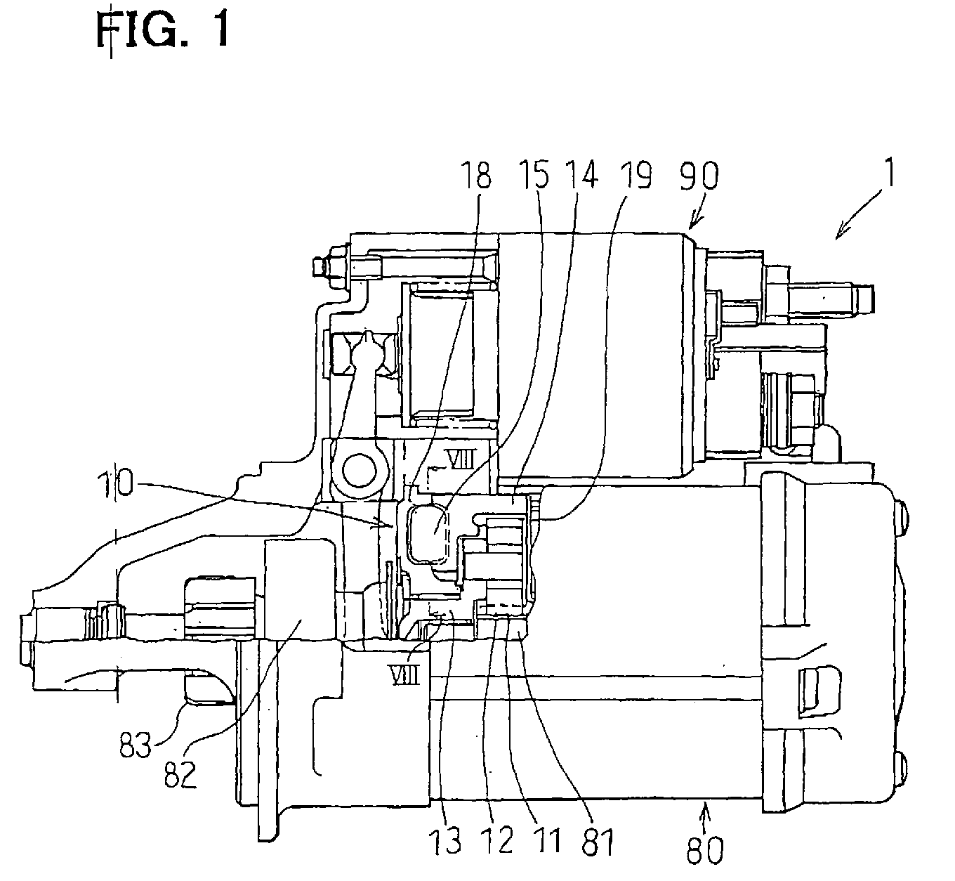
- Fig. 1 is a general view of a starting apparatus, partly including a cross-section, according to a first embodiment of the present invention;
- Fig. 2 is a perspective view of a cylindrical resin member of the starting apparatus according to the first embodiment of the present invention;
- Fig. 3 is a plan view of a shock absorbing member of the starting apparatus according to the first embodiment of the present invention;
- Fig. 4 is a perspective view of a containing case of the starting apparatus according to the first embodiment of the present invention;
- Fig. 5 is an exploded view of a rotation restricting unit according to the first embodiment of the present invention;
- Fig. 6 is a perspective view of the cylindrical resin member on which the shock absorbing member is mounted according to the first embodiment of the present invention;
- Figs. 7A and 7B are planarly developing views showing operation of the rotation restricting unit, in which Fig. 7A shows a state before operation of the starting apparatus and Fig. 7B shows a state during the operation of the starting apparatus; and
- Fig. 8 is a semi-cross-sectional view of the rotation restricting unit taken along a line VIII-VIII in Fig. 1;
- Fig- 9 is a semi-cross-sectional view of the rotation restricting unit according to a second embodiment of the present invention; and
- Fig. 10 is a semi-cross-sectional view of the rotation restricting unit according to a third embodiment of the present invention.
-
- Embodiments of the present invention will be described hereinafter with reference to the drawings.
- Referring to Fig. 1, a starting apparatus of the first embodiment of the present invention is for example employed to a gear type starter (hereinafter, simply referred to as "starter") 1. The
starter 1 mainly includes a reduction gear 10, amotor 80 and amagnet switch 90. An output of themotor 80 is transmitted from acarrier 13 to an output shaft formed with a helical spline at an outer peripheral face thereof, through the reduction gear 10. An overrunning clutch (one way clutch) 82 and apinion gear 83 are arranged on the helical spline. In starting, the overrunningclutch 82 and thepinion gear 83 are pushed in an axially forward direction (to a left side of Fig. 1) by lever operation of themagnet switch 90. Further, thepinion gear 83 is temporarily brought in mesh with a ring gear attached to a crankshaft of the engine, to thereby crank the engine. When the engine has been started, thepinion gear 83 of thestarter 1 is idly rotated by the overrunningclutch 82, to thereby restrict excessive rotation of themotor 80. - Meanwhile, the reduction gear 10 is constructed of a
sun gear 11, threeplanetary gears 12, thecarrier 13, acylindrical resin member 14, a containing case (case) 18, andshock absorbing members 15. Thesun gear 11 is formed at a motormain shaft 81 extending from themotor 80. The threeplanetary gears 12 are arranged at the periphery of thesun gear 11. Theplanetary gears 12 mesh with thesun gear 11. Thecarrier 13 rotatably and revolvably supports the planetary gears 12. Thecylindrical resin member 14 is arranged on the outer periphery of the planetary gears 12. Thecylindrical resin member 14 is formed with aninternal gear 149 on a cylindrical inner face thereof, to mesh with the planetary gears 12. The containingcase 18 is arranged on an axially front side (left side of Fig. 1) of thecylindrical resin member 14. Theshock absorbing members 15 are interposed between thecylindrical resin member 14 and the containingcase 18. Acover plate 19 is provided on an axially rear face of thecylindrical resin member 19. Thecover plate 19 closes a front opening of a housing of themotor 80 and restricts an axially rearward movement of thecylindrical resin member 14. - The
cylindrical resin member 14, theshock absorbing member 15 and thecase 18 construct a rotation restricting unit. The rotation restricting unit is a feature of the embodiment and will be described in detail hereafter. - As shown in Fig. 2, the
cylindrical resin member 14 is substantially in a shape of a bottomed cylinder and is integrally molded by thermoplastic resin. Thecylindrical resin member 14 is arranged such that an annular bottom wall is located on a front side (left side in Fig. 2) and the cylindrical wall portion is located on a rear side (right side in Fig. 2). Theinternal gear 149 is integrally molded on the cylindrical inner face of the cylindrical wall portion. The annular bottomwall of thecylindrical resin member 14 is formed with three pairs ofmovable locking projections 141 andmovable contact projections 142. Themovable locking projections 141 and themovable contact projections 142 are radially formed at regular intervals in a circumferential direction and project in the axially forward direction. A wall thickness of themovable contact projection 142 is greater than a wall thickness of themovable locking projection 141 to be able to stably receive large reaction force. A specific shape of themovable contact projection 142 will be described later in detail. - Further, the
cylindrical resin member 14 is provided with an inner ring-like projection 145 and an outer ring-like projection 146. The inner ring-like projection 145 is formed along an inner peripheral end of the bottom wall and slightly projects in the axially forward direction. The outer ring-like projection 146 is formed along an outer peripheral end of the bottom wall and slightly projects in the axially forward direction. On the bottom wall of thecylindrical resin member 14, main movable recessedportions 143 and sub movable recessedportions 144, which are slightly recessed, are alternately formed by the inner ring-like projection 145, the outer ring-like projection 146, themovable locking projections 141, and themovable contact projections 142. Further, a ratio of circumferential lengths of the main movable recessedportion 143 and the sub movable recessedportion 144 can be easily adjusted by changing a position of themovable locking projection 141 between the adjacent twomovable contact projections 142. - As shown in Fig. 3, each of the
shock absorbing members 15 has a mainelastic block portion 151, a subelastic block portion 152 and a bridgingportion 153 bridging between the mainelastic block portion 151 and the subelastic block portion 152. Theshock absorbing member 15 is integrally molded by an oil resistant synthetic resin (NBR or the like). Theshock absorbing member 15 is made of the oil resistant synthetic resin because the rubber will not deteriorated even when grease used for reducing abrasive resistance or the like is adhered to the rubber. By this, the function of theshock absorbing member 15 will last for a long period of time. - Themain
elastic block portion 151 is in the form of a fan-shaped block and a periphery of substantially a central portion thereof is constricted. Further, on the outer peripheral end of the mainelastic block portion 151 that makes contact with thecase 18, semisphericalelastic projections 154 are formed on both its front face and its rear face. The subelastic block portion 152 is in the form of a fan-shaped block. A circumferential length of the subelastic block portion 152 is considerably shorter than that of the mainelastic block portion 151. In the embodiment, the circumferential ratio of the mainelastic block portion 151 to the subelastic block portion 152 is about 5 to 1. The bridgingportion 153 connects an inner end of the mainelastic block portion 151 and an inner end of the subelastic block portion 152 in a form of belt. - As shown in Fig. 4, the
case 18 is substantially in a form of a disk and formed by pertinently machining an aluminum alloy cast product. A front side (left side in Fig. 4) of thecase 18 is formed substantially in a shape of a planar plate. Three pairs ofunmovable locking projections 181 andunmovable contact projections 182 are formed on a rear face (right side in Fig. 4) of thecase 18. The three pairs of theunmovable locking projections 181 andunmovable contact projections 182 are arranged radially at regular intervals. Theunmovable locking projections 181 and theunmovable contact projections 182 project in the axially rearward direction. A wall thickness of theunmovable contact projection 182 is greater than a wall thickness of theunmovable locking projection 181 to stably receive large reaction force. A specific shape of theunmovable contact projection 182 will be described later in detail. - Further, the
case 18 is formed with an inner ring-like projection 185 and an outer ring-like projection 186. The inner ring-like projection projects from an inner peripheral end of thecase 18 in the axially rearward direction. The outer ring-like projection projects from an outer peripheral end of thecase 18 in the axially rearward direction. Main unmovable recessedportions 183 and sub unmovable recessedportions 184, which are recessed, are formed by the inner ring-like projection 185, the outer ring-like projection 186, theunmovable locking projections 181, and theunmovable contact projections 182 alternately in the circumferential direction. Further, a ratio of circumferential lengths of the main unmovable recessedportion 183 to the sub unmovable recessedportion 184 can be easily adjusted by changing the position of theunmovable locking projection 181 between the adjacent twounmovable contact projections 182. - Further, the
case 18 is provided with alocking piece 189 on its outer peripheral portion. Thelocking piece 189 is engaged with a housing of the starter 1 (not illustrated) to prevent thecase 18 from rotating in the circumferential direction. - Next, assembling of the
cylindrical resin member 14, theshock absorbing member 15 and thecase 18 will be described with reference to Figs. 5 and 6. Fig. 5 shows an exploded view of the three members. Fig. 6 shows thecylindrical resin member 14 on which theshock absorbing members 15 are mounted for convenience of explanation. In fact, theshock absorbing members 15 are mounted to the containingcase 18 first, then thecylindrical resin member 14 is integrated thereto. An explanation will be given as follows in view thereof. - First, the
shock absorbing members 15 are fixed to thecase 18. At this time, each of theshock absorbing members 15 is fitted between theunmovable locking projection 181 and theunmovable contact projection 182 of thecase 18. Then, thecylindrical resin member 14 is joined with thecase 18 such that themovable locking projection 141 of thecylindrical resin member 14 is inserted between the mainelastic block portion 151 and the subelastic block portion 152 of theshock absorbing member 15. Therefore,elastic block portion 151 and the subelastic block portion 152 elastically interpose themovable locking projection 141 between them. This fixing step of thecylindrical resin member 14 to theshock absorbing member 15 is performed at the respective three locations in the circumferential direction. By this, theunmovable locking projections 181 are generally interposed between themovable contact projections 142 of thecylindrical resin member 14 and the mainelastic block portions 151 of theshock absorbingmember 15. Further, the subelastic block portion 152 of theshock absorbing member 15 is elastically interposed between theunmovable contact portion 182 and themovable locking projection 141. - In a condition that the
cylindrical resin member 14 and thecase 18 are joined, the inner ring-like projection 145 and the outer ring-like projection 146 of thecylindrical resin member 14 are respectively opposed to the inner ring-like projection 185 and the outer ring-like projection 186 of the containingcase 18. Therefore, a hermetically sealed inner space are formed between thecylindrical resin member 14 and the containingcase 18. Theshock absorbing members 15 are contained in the inner space. Also, thecylindrical resin member 14 is elastically supported in the axial direction, that is, in a thrust direction relative to thecase 18 by theelastic projections 154 provided on both the front face and the rear face of the mainelastic block portions 151 of theshock absorbing member 15. Theelastic projection 154 is formed in the semispherical shape and makes point contact with the wall face. Therefore, pivoting of thecylindrical resin member 14 relative to thecase 18 is less likely to be hampered. Accordingly, wear, deterioration or the like of theelastic projection 154 is reduced. Further, since thecylindrical resin member 14 is supported by theelastic projections 154 at the three locations disposed at regular intervals in the circumferential direction, thecylindrical resin member 14 maintains a very stable position. Therefore, transmission loss of the drive force of theinternal gear 149 caused by an inclination or the like thereof, wear or the like thereof can be reduced. - Next, an operation of the rotation restricting unit will be described with reference to Figs. 7A and 7B. Fig. 7A shows the rotation restricting unit before starting the engine. Fig. 7B shows the rotation restricting unit after starting the engine.
- As shown in Fig. 7A, before the starting operation of the
starter 1, theshock absorbing member 15 is fitted in the main unmovable recessedportion 183, specifically, in a space defined by theunmovable locking projection 181, theunmovable contact projection 182 and themovable locking projection 141 in a condition being elastically compressed (pre-compression). Further, themovable contact projection 142 is loosely fitted in the sub unmovable recessedportion 184, that is, in a space defined by theunmovable locking projection 181 and anotherunmovable contact projection 182 that is adjacent to theunmovable locking projection 181 in the circumferential direction. Before operating thestarter 1, theshock absorbing member 15 is not substantially compressed except a pre-compression amount that is caused in mounting theshock absorbing member 15 to thecase 18. Also, themovable contact projection 142 is located at a position separate from theunmovable contact projection 182, that is, located on a side of theunmovable locking projection 181. - On the other hand, when the starter S starts operation, the
cylindrical resin member 14 receives the reaction force from theinternal gear 149 in a direction denoted by an arrow A1 (upward in Fig. 7B). By the reaction force, themovable locking projection 141 compresses the mainelastic block portion 151 in the direction A1 of the reaction force. In the embodiment, before starting thestarter 1, themovable locking projection 141 and the mainelastic block portion 151 are elastically in close contact with each other. Therefore, the reaction force operated to thecylindrical resin member 14 is mildly absorbed from the start by the mainelastic block portion 151 through themovable locking projection 141. Accordingly, it is less likely that shock load will be rapidly exerted thereto. Further, in the compressing operation, the main unmovable recessedportion 183 achieves a function of a guide groove. Theshock absorbing member 15 and themovable locking projection 141 are respectively guided thereby. Furthermore, the sub unmovable recessedportion 184 achieves a function of a guide groove. Themovable contact projection 142 is guided in the sub unmovable recessedportion 184. - When the reaction force is further increased and the compressed amount of the main
elastic block portion 151 by themovable locking projection 141 reaches a vicinity of a limit (for example, compressed amount of 30%), themovable contact projection 142, which moves integrally with themovable locking projection 141, is brought into contact with theunmovable contact projection 182 of thecase 18, which is fixed, as shown in Fig. 7B. Thereafter, the rotation of thecylindrical resin member 14 in the direction A1 of the reaction force is restricted. By the contact ofthemovable contact projection 142 and theunmovable contact projection 182, the compressed amount of the mainelastic block portion 151 is prevented from exceeding the limit compressed amount (maximum compressed amount). - Further, when the reaction force exerted to the
cylindrical resin member 14 is released after starting the engine or the like, theshock absorbing member 15 and thecylindrical resin member 14 return from the state shown in Fig. 7B to the state shown in Fig. 7A. At this time, themovable locking projection 141 is reversely rotated, that is, returns toward anotherunmovable contact projection 182, which is located on a lower side of Fig. 7. Inherently, the returning force is small and the subelastic block portion 152 exists between themovable locking projection 141 and theunmovable contact projection 182. At this time, therefore, shock load or the like is less likely to be applied to the respective portions and unpleasant sound or the like will not be caused at the surrounding. - Next, the specific shape and positional relationship between the
movable contact projection 142 and theunmovable contact projection 182 will de described with reference to Fig. 8. In Fig. 8, theshock absorbing members 15 are not illustrated for the convenience of explanation. - As shown in Fig. 8, the
movable contact projection 142 and theunmovable contact projection 182 have substantially trapezoidal-shaped cross-sections. Themovable contact portion 142 has side walls extending substantially in the radial direction. Theunmovable contact portion 182 hasside walls movable contact projection 142 and theunmovable contact projection 182 make contact with each other at theside walls movable contact projection 142 and theunmovable contact projection 182 in the radial direction. That is, themovable contact projection 142 and theunmovable contact projection 182 are formed such that outside diameter portions thereof are located in closer proximity to each other than their respective inside diameter portions. - More specifically, in the first embodiment, the side wall of the
movable contact projection 142, which faces theside wall 182a of theunmovable contact portion 182, is formed of anoutside diameter portion 142a and aninside diameter portion 142c. Theoutside diameter portion 142a is formed on a radial line from the center axis O. Theinside diameter portion 142c is formed on a broken line L1 that passes through the point T1 on the central line LL' and a point C1. The point C1 is located radially outside from the center axis O. Therefore, theinner side wall 142c is recessed from the radial line on which theouter side wall 142a lies in the direction separate from theunmovable contact projection 182. In other wards, theoutside diameter portion 142a leads theinside diameter portion 142c with respect to a radial line from the center axis O that passes through an inside diameter corner of theinside diameter portion 142c in its rotation direction. - Accordingly, when the
movable contact projection 142 is brought into contact with theunmovable contact projection 182, theoutside diameter portion 142a makes contact with theside wall 182a of theunmovable contact projection 182 first. - Next, the second embodiment of the present invention will be described with reference to Fig. 9. Also in the second embodiment, the
movable contact projection 142 and theunmovable contact projection 182 make contact with each other at the radially outside portions thereof first. In the second embodiment, themovable contact projection 142 has theside walls side walls side walls movable contact projection 142. The point C2 is located radially outside from the center axis O. - Also in the second embodiment, the outside diameter portions of the
movable contact projection 142 lead the inside diameter portions with respect to the radial lines from the center axis O that pass through the inside diameter portions in its rotation direction. Therefore, when themovable contact projection 142 is brought into contact with theunmovable contact projection 182, themovable contact projection 142 and theunmovable contact projection 182 make contact at the outside diameter portions thereof. - Next, the third embodiment of the present invention will be described with reference to Fig. 10. Also in the third embodiment, the angle defined between the
side walls movable contact projection 142 increases with the distance from the center axis O. Specifically, theside walls movable contact portion 142. The point C3 is located radially outside from the center axis O. - Similar to the first and the second embodiments, the
movable contact projection 142 and theunmovable contact projection 182 make contact with each other at the outside diameter portions thereof first. - In the first to the third embodiments, the side walls of the
movable contact projection 142 are changed in various ways. Alternatively, the side walls of theunmovable contact projection 182 can be changed. The sidewalls 182a, 182b of theunmovable contact projection 182 may be formed in manners similar to theside walls mocavle contact projection 142. Further, the above described side walls can be employed to both themovable contact projection 142 and theunmovable contact projection 182 in various combinations. - According to the
starter 1 of the embodiments, theinternal gear 149 is restricted from rotating at least in one direction by the rotation restricting unit constructed of themovable locking portion 141, theunmovable locking portion 181, theshock absorbing member 15, themovable contact portion 142 and theunmovable contact portion 182. - In starting the engine by the
starter 1, the reaction force exerted to the internal gear 140 is received by theunmovable locking portion 181 through themovable locking portion 141 and theshock absorbing member 15. Thus, theinternal gear 149 is restricted from rotating in the direction of the reaction force. The reaction force is received by theunmovable locking portion 181 elastically and gently by presence of theshock absorbing member 15. Therefore, shock load is not applied to the respective portions and unpleasant sound or the like will not be generated. Further, theshock absorbing member 15 functions as a vibration isolating member and therefore, can absorb vibration or sound generated at the reduction gear 10 or a surrounding thereof. In this way, the reduction gear 10 can reduce vibration, unpleasant sound or the like generated in operating thestarter 1 although the reduction gear 10 is provided with a comparatively simple structure. - Even when the large reaction force is exerted to the
internal gear 149, rotation of theinternal gear 149 is restricted by bringing themovable contact portion 142 into contact with theunmovable contact portion 182. Therefore, a compressed amount of theshock absorbing member 15 is limited within a predetermined range. Thereby, destruction, damage, early fatigue or the like of theshock absorbing member 15 by an excessively large compressed amount can be restricted beforehand. Further, reliability of theshock absorbing member 15 and therefore, reliability of thestarter 1 is improved. Further, themovable contact portion 142 and theunmovable contact portion 182 function as the detent, rotation of theinternal gear 149 is restricted and therefore, an input from thedrive motor 80 is outputted from thecarrier 13 by reducing speed thereof. - Since the
shock absorbing member 15 is elastically held between themovable locking portion 141 and theunmovable locking portion 181, load applied from themovable locking portion 141 to theshock absorbing member 15 is elastic and gradual from start of operating thestarter 1. Further, when theshock absorbing member 15 returns after starting the engine, themovable locking portion 141 gradually receives the return force. A state in which theshock absorbing member 15 is elastically held between themovable locking portion 141 and theunmovable locking portion 181 is achieved by, for example, fixing theshock absorbing member 15 between themovable locking portion 141 and theunmovable locking portion 181 while compressing theshock absorbing member 15 by a small amount. - In this way, the highly reliable and highly
efficient starter 1, which is capable of reducing unpleasant sound or the like, is provided. Further, a compressed amount allowed to the shock absorbing member (maximum compressed amount) 15 can easily be set to change by adjusting an interval betweenthemovable contact portion 142 and theunmovable contact portion 182 and therefore, a degree of freedom of designing the reduction gear 10 is increased. - Further, the
movable contact portion 142 and theunmovable contact portion 182, which provide the detent, are disposed to contact with each other at least at the outside diameter portions thereof first. Accordingly, the reaction force (rotational torque) , which is received between themovable contact portion 142 and theunmovable contact portion 182, are received at the position that is farther from the center axis O. Therefore, the force exerted to the contact portions M is reduced. Because it is less likely to cause cracks on themovable contact portion 142 and theunmovable contact portion 182, the reliability of thestarter 1 improves. Further, it is possible to increase the thickness of themovable contact portion 142 and theunmovable contact portion 182 at the outside diameter portions greater than the inside diameter portions. Therefore, themovable contact portion 142 and theunmovable contact portion 182 are easily reinforced. Even if casts having large tolerances and volume products are used, themovable contact portion 142 and theunmovable contact portion 182 canmake contact at the outside diameter portions. Therefore, it is less likely to cause cracks on the inside diameter portions of themovable contact portion 142 and theunmovable contact portion 182. - The
side wall 142a of themovable contact portion 142, which is adjacent to and makes contact with theside wall 182a of theunmovable contact portion 182 slightly protrudes toward theunmovable contact portion 182 from the radial line passing through the inside diameter portion thereof. It is not always necessary that theside wall 142a is flat. Theside wall 142a can be curved from the inside diameter portion to the outside diameter portion. Theside wall 182a of theunmovable contact portion 182 can be formed such that the outside diameter portion thereof protrudes more than the inside diameter portion thereof with respect to a radial line from the center axis O that passes through the inside diameter portion. Also, theopposite side wall 182b of theunmovable contact portion 182 can be formed similar to theside wall 182a. Since it is not limited to the rotational direction of thestarter 1, this arrangement improves general versatility of the parts. Themovable contact portion 142 and theunmovable contact projection 182 are disposed to make contact with each other at least at the outside diameter portions first. Thereafter, thecontact projections portions - The
shock absorbing member 15 can be provided by such as a spring, synthetic resin, synthetic rubber or the like. In a case that theshock absorbing member 15 is in the shape of the elastic block, it is preferable that theshock absorbing member 15 is made of synthetic rubber in view of function, reliability, cost, integration performance or the like. In this case further, it is preferable that themovable contact portion 142 and theunmovable contact portion 182 are arranged such that a maximum compression rate of theshock absorbing member 15 is in a range of 10 % through 30%. - In general, an allowable maximum compression rate of synthetic rubber is normally set to be around 20% in consideration of durability thereof. However, since the
shock absorbing member 15 is used in a short period of time in starting the engine as in theshock absorbing member 15, even in the case in which the compression rate exceeds 20%, the reliability is not deteriorated for a long period of time. However, if the compression rate exceeds 30%, it is not preferable because theshock absorbing member 15 may be destructed or damaged. Hence, in the embodiments, the compression rate is confined in 30%. Further, an upper limit of the compression rate can be easily restricted by the contact of themovable contact portion 142 and theunmovable contact portion 182. A lower limit of the compression rate is set to 10% for effectively utilizing elasticity of theshock absorbing member 15. - In order to gently absorb the reaction force exerted to the
internal gear 149 by theshock absorbing member 15, it is necessary that theshock absorbing member 15 per se is easy to deform. Hence, theshock absorbing member 15 includes the mainelastic block portion 151 having the mainelastic block portion 151. The central portion with respect to the circumferential direction of the mainelastic block portion 151 is constricted more slenderly than an end portion thereof. Also, the mainelastic block portion 151 is compressible in the circumferential direction. Therefore, at least deformation resistance of the central portion is reduced. Further, when theshock absorbing member 15 is compressed, the constricted portion is expanded to the surrounding. Thus, the shape is changed in accordance with compress ion at the portion and therefore, elasticity of theshock absorbing member 15 is effectively utilized. In this way, by providing the constricted portion substantially at the center, theshock absorbing member 15 having large shock absorbing function is provided. Further, theshock absorbing member 15 is not constricted at the end portion and therefore, both the end portions of theshock absorbing member 15 are stably held by themovable locking portion 142 and theunmovable locking portion 182. - In fact, a direction of force operated to the
movable locking portion 142 is changed before and after starting the engine. Therefore, themovable locking portion 142 and theinternal gear 149 can be rotated in a direction opposite to the direction Al of the reaction force. At this time, vibration or unpleasant sound may be generated by the reduction gear although an amount thereof is small. Hence, theshock absorbing member 15 further includes the subelastic blockportion 152 elastically held between themovable locking portion 141 and theunmovable contact portion 182 and the bridgingportion 153 connecting between the mainelastic block portion 151 and the subelastic block portion 152 to span themovable locking portion 141. The ratio of the circumferential length of the mainelastic block portion 151 to that of the subelastic block portion 152 is preferably in a range of 4 through 6. - Thereby, the
movable locking portion 141 is elastically held by the subelastic block portion 152 on the side opposite to the mainelastic block portion 151. As a result, themovable locking portion 141 and theinternal gear 149 are elastically held in both the rotational directions. Themovable locking portion 141 is held further stably. Therefore, unpleasant sound or the like generated by the reduction gear 10 can be reduced. Further, since the mainelastic block portion 151 and the subelastic block portion 152 are connected by the bridgingportion 153 and therefore, integration or part control is facilitated. - Here, the ratio of the circumferential length of the main
elastic block portion 151 to that of the subelastic block portion 152 is in the range of 4 through 6 because the reaction force in starting, which is exerted in a direction of compressing the mainelastic block portion 151, is larger than the opposite force exerted in a direction of compressing the subelastic block portion 152. When the ratio of the circumferential length is less than 4, it is difficult to ensure durability of the mainelastic block portion 151. On the other hand, when the ratio of the circumferential length is greater than 6, it is difficult to achieve compact formation. Further, the ratio of circumferential length may be compared by lengths of center circle arcs of the mainelastic block portion 151 and the subelastic block portion 152. - Although the shape, the number or the like of the
shock absorbing member 15 is not particularly limited, it is preferable to arrange theshock absorbing members 15 respectively uniformly at three locations ormore in the circumferential direction in order to achieve compact formation of thestarter 1 and stable operation of theinternal gear 149. Hence, three sets or more of themovable locking portions 141, themovable contact portions 142, theunmovable locking portions 181 and theunmovable contact portions 182 are respectively arranged at regular intervals in the circumferential direction. Theshock absorbing members 15 are respectively arranged between themovable locking portions 141 and theunmovable locking portions 181. - Accordingly, inclination or deviation of the
internal gear 149 in starting can be restricted and thestarter 1 can be operated smoothly. Further, the reaction force in starting can be received by a plurality of theshock absorbing members 15 and therefore, theshock absorbing members 15 can be decreased in size and stable shock absorbing function can be achieved. - In the case of providing the
shock absorbing members 15 at a plurality of locations, theshock absorbing members 15 can be integrated into a ring-like shape in view of part control, integration or the like. However, it is preferable to provide theshock absorbing members 15 separately. Because promotion of reliability of theshock absorbing members 15 is achieved by preventing dragging between theshock absorbing members 15 in accordance with compression of the mainelastic block portion 151. - Although the
movable locking portion 141 and themovable contact portion 142 are disposed to rotate with theinternal gear 149, it is not always necessary that themovable locking portion 141 and themovable contact portion 142 are integrated into a single piece. For example, theinternal gear 149, themovable locking portion 141, and themovable contact portion 142 are provided as the separate parts, and are joined to have a locking relationship so as to rotate integrally. - In the embodiments, the
movable locking portion 141, themovable contact portion 142 and theinternal gear 149 are integrally formed into the single part. Therefore, part control and assembly are facilitated. Even when the part has a complicated shape, the part can comparatively easily be provided at low cost by integral molding of resin. Hence, it is preferable that themovable locking portion 141, themovable contact portion 142, and theinternal gear 149 are provided by the res in member having the substantially bottomed cylindrical shape, which is integrally molded by a resin. Theinternal gear 149 is inner teeth formed on an inner peripheral wall of the cylindrical portion of thecylindrical resin member 14. Themovable locking portion 141 and themovable contact portion 142 project in the axially outward direction from the bottom face of the resin member. - In the embodiments, shock of reaction force or the like exerted to the
internal gear 149 and themovable locking portion 141 can be absorbed by theshock absorbing member 15. Therefore, even when the members are integrally molded by resin, the members are not destructed or damaged and are excellent in wear resistance. Accordingly, reliability is improved. - Since the rotation of the
unmovable locking portion 181 and theunmovable contact portion 182 is constricted, theunmovable locking portion 181 and theunmovable contact portion 182 are provided separately from the above resin member. Theunmovable locking portion 181 and theunmovable contact portion 182 are formed in thecase 18 to project from the bottom wall of the case in the axial direction. Theunmovable locking portion 181 and theunmovable contact portion 182 are accommodated in the recessed portion formed in the cylindrical portion of thecase 18. - Although an explanation has been given of a case in which the
internal gear 149 is pivoted in the circumferential direction, in consideration of various vibrations applied to theinternal gear 149, integration tolerance or the like, it is preferable that theinternal gear 149 is elastically held also in the axial direction. Hence, theshock absorbing member 15 is provided with the elastic projectedportions 154 extending in the axial direction. In this case, the elastic projectedportions 154 are disposed on the side of theunmovable locking portion 181. Thus, the elastic projectedportions 154 achieve a stable holding function. When the elastic projectedportions 154 are formed on the side of theunmovable locking portion 181, the elastic projectedportions 154 will less likely to be dragged with the rotation of themovable locking portion 141. Therefore, the elastic projectedportions 154 achieve stable holding function in the axial direction. Further, since the elastic projectedportion 154 has the semispherical shape, the elastic projectedportion 154 makes a point contact with a sliding surface. Therefore, abrasion resistance is reduced and theinternal gear 149 is smoothly pivoted. Further, since the sliding area is small, wear, damage or deterioration of theshock absorbing member 15 is reduced. - In this way, the
starter 1 receives the reaction force in operating the starter by theshock absorbing member 15 while alleviating the reaction force. Therefore, damage or the like to the respective parts are reduced. The reliability of thestarter 1 is improved. - In the specification, "unmovable" state referring to the unmovable locking portion or the unmovable contact portion, signifies that the portion is not substantially pivoted and more or less play or the like is not problematic thereby.
- Further, the
starter 1 of the invention is not limited to the gear type starter but may be other type of starter. Further, "circumferential direction" or "axial direction" in the specification is defined relative to the rotation center axis O of the reduction gear 10. - The present invention should not be limited to the disclosed embodiment, but may be implemented in other ways without departing from the spirit of the invention.
Claims (6)
- A starting apparatus (1) for starting an engine comprising:a drive motor (80) generating a rotational force;a reduction gear device (10) including:a sun gear (11) disposed to rotate by receiving the rotational force from the drive motor (80);an internal gear (149) arranged concentrically with the sun gear (11) on an outer periphery of the sun gear (11) and rotatable in a circumferential direction;a planetary gear (12) meshing with the sun gear (11) and the internal gear (149);a carrier (13) rotatably supporting the planetary gear (12) and outputting the rotation of the sun gear (11) by reducing a speed thereof; anda rotation restricting unit (14, 15, 18) to restrict rotation of the internal gear (149), wherein the rotation restricting unit includes;a movable locking portion (141) provided to move with the internal gear (149) in the circumferential direction;a movable contact portion (142) disposed at a predetermined distance from the movable locking portion (141) in the circumferential direction and movable with the movable locking portion (141);an unmovable locking portion (181) held in a state unmovable in the circumferential direction and opposed to the movable locking portion (141) in the circumferential direction;an unmovable contact portion (182) held in a state unmovable in the circumferential direction and opposed to the movable contact portion (142) in the circumferential direction; anda shock absorbing member (15) elastically held between the movable locking potion (141) and the unmovable locking portion (181) for elastically receiving a reaction force applied to the internal gear (149) when the drive motor (80) starts to rotate the engine via the reduction gear device (10), wherein a compression amount of the shock absorbing member (15) is restricted by bringing the movable contact portion (142) into contact with the unmovable contact portion (182), and wherein the movable contact portion (142) and the unmovable contact portion (182) are disposed such that the movable contact portion (142) and the unmovable contact portion (182) make contact at least at outside diameter portions (M) thereof first when the movable contact portion (142) is brought into contact with the unmovable contact portion (182).
- The starting apparatus according to claim 1, wherein
the movable contact portion (142) has a first side wall (142a, 142c) and a second side wall (142b) opposite to each other in the circumferential direction, the first side wall (142a, 142c) facing the unmovable contact portion (182),
the movable contact portion (142) is disposed such that an outside diameter portion (142a) of the first side wall leads an inside diameter portion (142c) of the first side wall with respect to a radial line from a center axis (O) of the rotation restricting unit in its rotation direction, the radial line passing through the inside diameter portion of the first side wall. - The starting apparatus according to claim 2, wherein the second side wall (142b) of the movable contact portion (142) is disposed such that an outs ide diameter portion thereof leads an inside diameter portion thereof with respect to a radial line from the center axis (O) of the rotation restricting unit in its rotation direction, the radial line passing through the inside diameter portion of the second side wall (142b).
- The starting apparatus according to any one of claims 1 to 3, wherein
the unmovable contact portion (182) has a first side wall (182a) and a second side wall (182b) opposite to each other in the circumferential direction, the first side wall (182a) facing the movable contact portion (142),
the first side wall (182a) is disposed such that an outside diameter portion thereof protrudes more than an inside diameter portion thereof with respect to a radial line from the center axis (O) of the rotation restricting unit, the radial line passing through the inside diameter portion of the first side wall (182a). - The starting apparatus according to any one of claims 1 to 4, wherein the movable contact portion (142) and the unmovable contact portion (182) are disposed such that outside diameter portions thereof are located in closer proximity to each other than their respective inside diameter portions.
- The starting apparatus according to claim 5, wherein
the rotation restricting unit further includes a cylindrical resin member (14) and a case member (18) opposed to each other in an axial direction, wherein
the internal gear (149) is provided on an inner wall of the cylindrical resin member (14),
the movable contact portion (142) and the movable locking portion (141) are formed on the cylindrical resin member (14) to protrude in the axial direction toward the case member (18), and
the unmovable contact portion (182) and the unmovable locking portion (181) are formed on the case member (18) to protrude in the axial direction toward the cylindrical resin member (14).
Applications Claiming Priority (2)
| Application Number | Priority Date | Filing Date | Title |
|---|---|---|---|
| JP2003041295 | 2003-02-19 | ||
| JP2003041295A JP4135524B2 (en) | 2003-02-19 | 2003-02-19 | Starter |
Publications (2)
| Publication Number | Publication Date |
|---|---|
| EP1450038A1 true EP1450038A1 (en) | 2004-08-25 |
| EP1450038B1 EP1450038B1 (en) | 2006-04-12 |
Family
ID=32732942
Family Applications (1)
| Application Number | Title | Priority Date | Filing Date |
|---|---|---|---|
| EP04003636A Expired - Lifetime EP1450038B1 (en) | 2003-02-19 | 2004-02-18 | Starting apparatus |
Country Status (4)
| Country | Link |
|---|---|
| US (1) | US6997072B2 (en) |
| EP (1) | EP1450038B1 (en) |
| JP (1) | JP4135524B2 (en) |
| DE (1) | DE602004000614T2 (en) |
Cited By (3)
| Publication number | Priority date | Publication date | Assignee | Title |
|---|---|---|---|---|
| FR2944325A1 (en) * | 2009-04-10 | 2010-10-15 | Denso Corp | STARTER WITH NOISE REDUCTION STRUCTURE. |
| FR2997732A1 (en) * | 2012-11-08 | 2014-05-09 | Valeo Equip Electr Moteur | THERMAL MOTOR STARTER PROVIDED WITH SHEAR ABSORPTION DEVICE |
| EP2769082B1 (en) * | 2011-10-14 | 2025-04-09 | Valeo Electrification | Starter for combustion engine |
Families Citing this family (4)
| Publication number | Priority date | Publication date | Assignee | Title |
|---|---|---|---|---|
| US6993989B2 (en) * | 2002-04-26 | 2006-02-07 | Denso Corporation | Starting apparatus |
| JP4380595B2 (en) | 2005-05-31 | 2009-12-09 | 株式会社デンソー | Starter |
| JP5176868B2 (en) * | 2008-10-24 | 2013-04-03 | 株式会社デンソー | Starter |
| US9376999B2 (en) * | 2013-08-22 | 2016-06-28 | Paul H. Sloan, Jr. | Engine starter inertia drive |
Citations (4)
| Publication number | Priority date | Publication date | Assignee | Title |
|---|---|---|---|---|
| FR516919A (en) * | 1918-06-29 | 1921-04-28 | Max Wild | Starter device particularly for automobile engines |
| US4680979A (en) * | 1984-12-20 | 1987-07-21 | Mitsubishi Denki Kabushiki Kaisha | Planetary gear starter |
| JPH0552166A (en) * | 1991-08-22 | 1993-03-02 | Nippondenso Co Ltd | Starter |
| US5199309A (en) * | 1990-12-28 | 1993-04-06 | Mitsubishi Denki K.K. | Starter unit |
Family Cites Families (7)
| Publication number | Priority date | Publication date | Assignee | Title |
|---|---|---|---|---|
| JPS5853857U (en) * | 1981-10-09 | 1983-04-12 | 三菱電機株式会社 | starter |
| JP3603508B2 (en) * | 1996-02-15 | 2004-12-22 | 株式会社デンソー | Starter |
| US5905309A (en) * | 1996-02-15 | 1999-05-18 | Denso Corporation | Starter with shock absorbing device |
| FR2803345B1 (en) * | 1999-12-30 | 2002-03-01 | Valeo Equip Electr Moteur | STARTER EQUIPPED WITH A SHOCK ABSORBER AND TORQUE LIMITER |
| DE10016706A1 (en) * | 2000-04-05 | 2001-10-11 | Bosch Gmbh Robert | Starting device |
| JP2002180938A (en) * | 2000-12-08 | 2002-06-26 | Denso Corp | Starter |
| US6993989B2 (en) | 2002-04-26 | 2006-02-07 | Denso Corporation | Starting apparatus |
-
2003
- 2003-02-19 JP JP2003041295A patent/JP4135524B2/en not_active Expired - Fee Related
-
2004
- 2004-02-18 EP EP04003636A patent/EP1450038B1/en not_active Expired - Lifetime
- 2004-02-18 DE DE602004000614T patent/DE602004000614T2/en not_active Expired - Lifetime
- 2004-02-19 US US10/780,769 patent/US6997072B2/en not_active Expired - Lifetime
Patent Citations (4)
| Publication number | Priority date | Publication date | Assignee | Title |
|---|---|---|---|---|
| FR516919A (en) * | 1918-06-29 | 1921-04-28 | Max Wild | Starter device particularly for automobile engines |
| US4680979A (en) * | 1984-12-20 | 1987-07-21 | Mitsubishi Denki Kabushiki Kaisha | Planetary gear starter |
| US5199309A (en) * | 1990-12-28 | 1993-04-06 | Mitsubishi Denki K.K. | Starter unit |
| JPH0552166A (en) * | 1991-08-22 | 1993-03-02 | Nippondenso Co Ltd | Starter |
Cited By (4)
| Publication number | Priority date | Publication date | Assignee | Title |
|---|---|---|---|---|
| FR2944325A1 (en) * | 2009-04-10 | 2010-10-15 | Denso Corp | STARTER WITH NOISE REDUCTION STRUCTURE. |
| EP2769082B1 (en) * | 2011-10-14 | 2025-04-09 | Valeo Electrification | Starter for combustion engine |
| FR2997732A1 (en) * | 2012-11-08 | 2014-05-09 | Valeo Equip Electr Moteur | THERMAL MOTOR STARTER PROVIDED WITH SHEAR ABSORPTION DEVICE |
| WO2014072651A3 (en) * | 2012-11-08 | 2014-07-17 | Valeo Equipements Electriques Moteur | Heat engine starter provided with a device for shock absorption by shearing |
Also Published As
| Publication number | Publication date |
|---|---|
| DE602004000614T2 (en) | 2007-05-03 |
| JP4135524B2 (en) | 2008-08-20 |
| US20040231442A1 (en) | 2004-11-25 |
| JP2004251168A (en) | 2004-09-09 |
| EP1450038B1 (en) | 2006-04-12 |
| DE602004000614D1 (en) | 2006-05-24 |
| US6997072B2 (en) | 2006-02-14 |
Similar Documents
| Publication | Publication Date | Title |
|---|---|---|
| EP1357287B1 (en) | Starting apparatus | |
| KR100671579B1 (en) | Vehicle starter | |
| US5323663A (en) | Starter | |
| JP4508027B2 (en) | Internal combustion engine starting torque transmission mechanism | |
| JP4174820B2 (en) | Starter | |
| CN115571028B (en) | Drive device, seat assembly, and vehicle having the same | |
| US6997072B2 (en) | Starting apparatus | |
| EP0790405B1 (en) | Starter having planetary gear reduction device | |
| CN1066524C (en) | Stepless transmitter | |
| JPH1182041A (en) | Power transmission device for internal combustion engine | |
| JP4339584B2 (en) | Starter | |
| CN114851925A (en) | Seat height adjuster and seat height adjusting device | |
| JP2002180936A (en) | Starter | |
| US6957594B2 (en) | Starter having helical ventilation groove in tube | |
| JP4573589B2 (en) | V belt type continuously variable transmission | |
| JPH08326640A (en) | Starter | |
| JP3897252B2 (en) | Starter | |
| JP3389921B2 (en) | Starter | |
| CN100404911C (en) | V shape belt type stepless gear | |
| US20080004147A1 (en) | Starter | |
| JP2003314418A (en) | Starting device | |
| CN1078688C (en) | Centrifugal clutch | |
| KR101247492B1 (en) | Friction clutch, in particular for motor vehicle, of the type comprising an improved shock absorber | |
| JP2006125325A (en) | Starter | |
| JP2004011845A (en) | Planetary gear reducer and battery-driven device using the same |
Legal Events
| Date | Code | Title | Description |
|---|---|---|---|
| PUAI | Public reference made under article 153(3) epc to a published international application that has entered the european phase |
Free format text: ORIGINAL CODE: 0009012 |
|
| AK | Designated contracting states |
Kind code of ref document: A1 Designated state(s): AT BE BG CH CY CZ DE DK EE ES FI FR GB GR HU IE IT LI LU MC NL PT RO SE SI SK TR |
|
| AX | Request for extension of the european patent |
Extension state: AL LT LV MK |
|
| 17P | Request for examination filed |
Effective date: 20040811 |
|
| 17Q | First examination report despatched |
Effective date: 20050201 |
|
| AKX | Designation fees paid |
Designated state(s): DE FR IT |
|
| GRAP | Despatch of communication of intention to grant a patent |
Free format text: ORIGINAL CODE: EPIDOSNIGR1 |
|
| RBV | Designated contracting states (corrected) |
Designated state(s): DE FR IT |
|
| GRAS | Grant fee paid |
Free format text: ORIGINAL CODE: EPIDOSNIGR3 |
|
| RAP1 | Party data changed (applicant data changed or rights of an application transferred) |
Owner name: DENSO CORPORATION |
|
| GRAA | (expected) grant |
Free format text: ORIGINAL CODE: 0009210 |
|
| AK | Designated contracting states |
Kind code of ref document: B1 Designated state(s): DE FR IT |
|
| PG25 | Lapsed in a contracting state [announced via postgrant information from national office to epo] |
Ref country code: IT Free format text: LAPSE BECAUSE OF FAILURE TO SUBMIT A TRANSLATION OF THE DESCRIPTION OR TO PAY THE FEE WITHIN THE PRESCRIBED TIME-LIMIT;WARNING: LAPSES OF ITALIAN PATENTS WITH EFFECTIVE DATE BEFORE 2007 MAY HAVE OCCURRED AT ANY TIME BEFORE 2007. THE CORRECT EFFECTIVE DATE MAY BE DIFFERENT FROM THE ONE RECORDED. Effective date: 20060412 |
|
| REF | Corresponds to: |
Ref document number: 602004000614 Country of ref document: DE Date of ref document: 20060524 Kind code of ref document: P |
|
| ET | Fr: translation filed | ||
| PLBE | No opposition filed within time limit |
Free format text: ORIGINAL CODE: 0009261 |
|
| STAA | Information on the status of an ep patent application or granted ep patent |
Free format text: STATUS: NO OPPOSITION FILED WITHIN TIME LIMIT |
|
| 26N | No opposition filed |
Effective date: 20070115 |
|
| PG25 | Lapsed in a contracting state [announced via postgrant information from national office to epo] |
Ref country code: IT Free format text: LAPSE BECAUSE OF NON-PAYMENT OF DUE FEES Effective date: 20100218 |
|
| PGRI | Patent reinstated in contracting state [announced from national office to epo] |
Ref country code: IT Effective date: 20141217 |
|
| REG | Reference to a national code |
Ref country code: FR Ref legal event code: PLFP Year of fee payment: 13 |
|
| REG | Reference to a national code |
Ref country code: FR Ref legal event code: PLFP Year of fee payment: 14 |
|
| REG | Reference to a national code |
Ref country code: FR Ref legal event code: PLFP Year of fee payment: 15 |
|
| PGFP | Annual fee paid to national office [announced via postgrant information from national office to epo] |
Ref country code: DE Payment date: 20190219 Year of fee payment: 16 Ref country code: IT Payment date: 20190225 Year of fee payment: 16 |
|
| PGFP | Annual fee paid to national office [announced via postgrant information from national office to epo] |
Ref country code: FR Payment date: 20190219 Year of fee payment: 16 |
|
| REG | Reference to a national code |
Ref country code: DE Ref legal event code: R119 Ref document number: 602004000614 Country of ref document: DE |
|
| PG25 | Lapsed in a contracting state [announced via postgrant information from national office to epo] |
Ref country code: DE Free format text: LAPSE BECAUSE OF NON-PAYMENT OF DUE FEES Effective date: 20200901 Ref country code: FR Free format text: LAPSE BECAUSE OF NON-PAYMENT OF DUE FEES Effective date: 20200229 |
|
| PG25 | Lapsed in a contracting state [announced via postgrant information from national office to epo] |
Ref country code: IT Free format text: LAPSE BECAUSE OF NON-PAYMENT OF DUE FEES Effective date: 20200218 |