TECHNICAL FIELD
The present invention relates to a technology for extending the life span of a member
for use in high-temperature equipment, such as a gas turbine blade, a turbine blade for a jet
engine or a boiler tube.
BACKGROUND ART
(1) Thermal Barrier Coating (TBC)
A high-temperature equipment member, such as an industrial gas turbine blade or a
boiler tube, has a coated surface to obtain enhanced heat resistance and corrosion resistance,
in many cases. With regard to heat resistance, a ceramics coating, so-called thermal barrier
coating (TBC), is typically applied to the equipment member.
In use of ceramics, an alloy layer, so-called undercoat (or bondcoat), is generally
inserted between a ceramics layer and a metal substrate to assure adhesion therebetween,
because the relatively large difference in thermal expansion coefficient between ceramics and
substrate metal is likely to cause peeling of the ceramics layer at the TBC/substrate interface.
However, under an ultra-high temperature environment of about 800 to 1200°C, the undercoat
will be deteriorated due to reaction with the substrate, or the peeling of the ceramics layer
will occur due to an oxide layer thickly grown on the surface of the undercoat. This leads to
a serious problem that the equipment member has a short life span of several months.
(2) Al (or Cr, Si) Diffusion Coating Process
With regard to corrosion resistance, the equipment member is typically subjected to an
Al (or Cr, Si) diffusion coating process. However, under an ultra-high temperature
environment of about 800 to 1200°C, a protective film cannot be stably maintained for a long
time-period due to significantly high diffusion rate and high reactivity of a metal element
contributing to corrosion resistance. Further, under a severe corrosive environment
containing Cl or S, an metal element, such as Cr or Al, constituting the protective film will be
quickly consumed even in a temperature range of 500 to 800°C, which leads to difficulties in
maintaining the protective film stably for a long time-period, and a serious problem of
significantly shortened life span in the equipment member.
(3) Ni-Cr Thermal Spraying
For providing enhanced corrosion resistance, a high Ni-high Cr alloy thermal sprayed
coating is applied to the equipment member, in some cases. However, this case involves the
same problem as that in the above (2).
(4) TBC System combined with Re-added Undercoat
Japanese Patent Laid-Open Publication No. 11-61439 discloses a TBC system including
an undercoat with Re (Rhenium) added thereto at 12 weight% or more (several % by atomic
composition). Japanese Patent Laid-Open Publication No. 2000-511236 titled "Structural
Component including Superalloy Substrate and Layer Structure formed thereon, and
Production Method thereof" discloses an undercoat for a TBC, containing Re in the range of
35 to 60 weight% (about 15 to 30% by atomic composition). These publications discloses
neither the function of Re nor the effect of the Re addition. U.S. Patent No. 6,299,986
discloses a superalloy article in which a barrier coating containing 4 wt% or less of Re is
formed on a Ni-based superalloy substrate containing 5.0 to 7.0 wt% of Re.
(5) Re Coating & Re alloy Coating
Japanese Patent Laid-Open Publication No. 03-120327 discloses a protective film
containing 1 to 20 wt% of Re and 22 to 50 wt% of Cr. Japanese Patent Laid-Open
Publication No. 09-143665 discloses a production method of a high-temperature member
comprising pure Re, Re-Mo alloy or Re-W alloy. The method disclosed in this publication
is intended to produce a Re or Re alloy structural member which is used independently in the
form of a thin plate.
DISCLOSURE OF INVENTION
Under existing circumstances involving the aforementioned unsolved problems, there is
no other choice but to lower the operating temperature of the high-temperature equipment at
the sacrifice of the performance thereof so as to assure a desired life span of the equipment
member.
Despite of various researches on a method using Re or Re alloy as a diffusion barrier,
the inventors could not find out an intended layer structure capable of stably providing a
diffusion barrier performance.
The present invention is directed to suppress the problem of the anti-corrosion coating
formed through the conventional TBC, system, Al (or Cr, Si) diffusion coating process or
thermal splaying, or the deterioration of a substrate and a coating layer due to the reaction
therebetween, so as to provide intended life span of a high-temperature equipment member.
A Re (or Ir, Rh, Pt, W) alloy layer can be coated on the surface of a substrate, or
inserted between a substrate and a TBC layer to provide an excellent diffusion barrier layer.
However, if Re in the Re alloy coating is contained at a low concentration, or a specific alloy,
such as Re-Ni binary alloy, incapable of forming a stable alloy phase with Re under high
temperature is used, a Re-Ni alloy phase will be separated into a Re-rich phase and a
counter-element (e.g. Ni)-rich phase, resulting in deteriorated diffusion barrier function.
Through researches based on diffusion tests using various Re alloys, the inventors have
found out that a ReCr alloy containing 50 to 90 atomic% of Re has a diffusion coefficient far
smaller than that of a ReCr alloy containing less than 30 atomic% of Re or a Re-Ni alloy, and
thus, among Re alloy coatings formed on a substrate, a ReCr alloy containing 50 atomic% or
more of Re exhibits particularly distinctive diffusion barrier function. The present invention
provides an excellent diffusion barrier layer based on the above knowledge.
Specifically, the present invention provides a ReCr alloy coating for diffusion barrier,
comprising an atomic composition of 50 % to less than 90 % Re, with the remainder
consisting essentially of Cr except for inevitable impurities. The ReCr alloy coating allows
the substrate to maintain an excellent heat resistance and corrosion resistance.
The alloy coating for diffusion barrier may include a stress relief layer inserted between
the substrate and the alloy coating. This structure can suppress a crack of the alloy coating
caused by the difference in thermal expansion between the substrate and alloy coating and the
substrate to maintain the alloy coating as a continuous layer, so as to more effectively utilize
the heat resistance and corrosion resistance of the alloy coating.
The alloy coating for diffusion barrier may further include a diffusion layer laminated
on the ReCr alloy coating. The diffusion layer contains at least one selected from the group
consisting of Al, Si and Cr. In this structure, the ReCr alloy coating can prevent the
diffusion of an element causing the deterioration of corrosion resistance (e.g. Ti, Nb, Ta) from
the substrate to the diffusion layer, and the diffusion of an element causing the deterioration
of phase stability (e.g. Al, Si, Cr) from the diffusion layer to the substrate. Thus, an
excellent oxidation resistance and the strength of the substrate can be maintained for a long
time-period.
The alloy coating for diffusion barrier may further include a heat barrier ceramics
laminated on the ReCr alloy coating. The heat barrier ceramics allows the above materials
to be used under high temperature.
BRIEF DESCRIPTION OF DRAWINGS
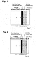
FIG 1 is a schematic diagram showing the sectional structure of a Ni-based alloy in
Inventive Example 1.
FIG. 2 is a schematic diagram showing the sectional structure of a Ni-based alloy in
Inventive Example 2.
FIGS. 3(a) to 3(d) are schematic diagrams showing the sectional structures of Ni-based
alloys in Comparative Examples 1 to 4, respectively.
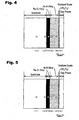
FIG 4 is a schematic diagram showing the sectional structure of the Ni-based alloy in
Inventive Example 1 after oxidized in the atmosphere at 1100°C for one month.
FIG 5 is a schematic diagram showing the sectional structure of the Ni-based alloy in
Inventive Example 2 after oxidized in the atmosphere at 1100°C for one month.
FIGS. 6(a) to 6(d) are schematic diagrams showing the sectional structures of Ni-based
alloys in Comparative Examples 1 to 4 after oxidized in the atmosphere at 1100°C for one
month, respectively.
FIG. 7 is a graph showing the thickness of an oxidized scale of each of Inventive
Examples 1 and 2 and Comparative Examples 1 to 4 after oxidized in the atmosphere at
1100°C for one month.
BEST MODE FOR CARRYING OUT THE INVENTION
The present invention will now be described in detail.
The present invention relates to a ReCr alloy coating for diffusion barrier, comprising an
atomic composition of 50 % to less than 90 % Re, with the remainder consisting essentially
of Cr except for inevitable impurities. The inventors have fund out that a Re alloy coating
can be used as a diffusion barrier layer because its metal elements have a lower diffusing
capacity than that of a Ni-based alloy coating and a Fe-based alloy coating, and a ReCr alloy
forms a σ phase capable of providing particularly distinctive diffusion barrier function among
the Re alloy coatings.
If Re is less than 50%, the rate of Cr-rich phase will be increased more than that of the σ
phase to o cause the deterioration in diffusion barrier function of the alloy coating. If Re is
greater than 90%, the rate of a Re single phase will be increased to cause slightly deteriorated
diffusion barrier function. Differently from a Re alloy phase, the Re single-phase is apt to
allow cracks to be introduced therein due to thermal shock. Further, due to poor adhesion
between the Re single-phase and the substrate, the alloy coating cannot stably exist as a
diffusion layer on the surface of the substrate for a long time-period. Therefore, the
concentration of Re is limited in the range of 50 % to less than 90 % by atomic composition.
Preferably, the concentration of Re is in the range of 55 % to 75 % by atomic composition.
While the ReCr alloy coating can be preferably formed through a magnetron sputtering
process, a physical deposition process, a chemical deposition process or thermal spraying
process may be used to form the same alloy coating. A process for forming the Re alloy
coating with the desired composition is not limited to these processes, but the desired Re
alloy coating may be formed by diffusing alloy components of the substrate to the film
through a heat treatment. In either case, the alloy coating is preferably subjected to a heat
treatment at a high temperature in vacuum under a non-oxidation atmosphere, such as an inert
atmosphere, to homogenize the composition and structure of the Re layer or Re alloy layer
coated on the substrate. In this manner, when the alloy coating for diffusion barrier of the
present invention includes a diffusion layer containing at least one selected from the group
consisting of Al, Si and Cr, the components of the substrate can be diffused while
substantially preventing the elements of Al, Si and Cr from being diffused.
When the alloy coating for diffusion barrier of the present invention includes a stress
relief layer inserted between the substrate and the alloy layer, the stress relief layer is
preferably a ReCr-(Ni, Fe, Co) alloy layer, for example, wherein the Re concentration is
reduced by about 5 to 20 atomic%, and the concentration of either one of Ni in a Ni-based
alloy substrate, Fe in a Fe-based alloy substrate, and Co in a Co-based alloy substrate, is
increased by about 5 to 20 atomic%, as compared to those of the diffusion barrier layer.
This structure can suppress cracks in the alloy coating due to the difference in thermal
expansion coefficient between the substrate and the alloy coating so as to maintain the alloy
coating as a continuous layer to more effectively bring out the heat resistance and corrosion
resistance of the alloy coating.
As a process for laminating the diffusion layer containing at least one selected from the
group consisting of Al, Si and Cr, a conventional process, such as a pack process or a CVD
process, may be appropriately used. For example, a receptor layer for Al, Si or Cr to be
diffused may be formed by plating a metal layer containing at least one selected from the
group consisting of Ni, Fe and Co, on a ReCr alloy coating, and subjecting the alloy coating
with the metal layer to a diffusion treatment at a high temperature to form an alloy layer
containing these elements.
When the alloy coating for diffusion barrier of the present invention further includes a
heat barrier ceramics laminated on the diffusion-barrier alloy coating, the ceramics preferably
includes at least one selected from the group consisting of ZrO2, CaO, MgO, SiO2 and Al2O3.
The heat barrier ceramics can provide a lower temperature of the internal alloy layer to
suppress the growth of oxide on the surface of the alloy coating and the diffusion between the
alloy coating and the substrate so as to maintain the structural stability of the alloy coating
and the substrate for an extended time-period.
[EXAMPLE]
[Inventive Example 1]
After an 55 atomic% Re-45 atomic% Cr alloy coating was coated on a Ni-based alloy of
Inconel 738LC (Ni-16% Cr-8.5% Co-0.9% Nb-1.7% Mo-2.6%W-3.4 Ti-3.4% Al (weight %))
for use in a rotor blade or stationary blade of a gas turbine, the Ni-based alloy was Ni-plated,
and then subjected to an Al diffusion coating. Specifically, the alloy coating was formed by
coating a 55 atomic% Re-45 atomic% Cr alloy on the surface of the substrate through a
magnetron sputtering process using the ReCr alloy as a target, and then subjecting the
substrate with the alloy layer to a homogenizing heat treatment in vacuum at 1100°C for 5
hours.
A Watts bath was used for the Ni plating. Specifically, the plating conditions were set
as follows: a bath composition [the weight ratio of NiSO4• 7H2O : NiCl2 : H3BO3 = 20 : 3 : 2],
pH = 5, a bath temperature of 50°C, and a current density of 50 mA/cm2. The Al diffusion
coating was performed under the condition that the substrate with coated Re alloy and
plated-Ni was heated at 1000°C in vacuum for 5 hours while being immersed in a mixed
powder of a Ni-50 atomic% Al alloy powder and an Al2O3 powder.
FIG 1 shows the sectional structure of the Ni-based alloy after the treatment. Further,
Table 1 shows the analysis result of the composition of each point in FIG 1 using an electron
probe microanalyzer (EPMA). The data (1) to (5) in Table 1 correspond to the points (1) to
(5) in FIG. 1, respectively.
| (atomic%) |
| | (1) | (2) | (3) | (4) | (5) |
| Re | 0.0 | 0.1 | 52.7 | 0.0 | 0.0 |
| Ni | 60.3 | 58.6 | 1.9 | 48.2 | 49.4 |
| Cr | 18.2 | 21.2 | 41.9 | 1.8 | 0.4 |
| Co | 8.0 | 7.5 | 1.2 | 0.2 | 0.1 |
| W | 1.0 | 0.6 | 1.0 | 0.0 | 0.0 |
| Mo | 0.8 | 0.7 | 0.8 | 0.0 | 0.0 |
| Ta | 0.4 | 0.4 | 0.1 | 0.0 | 0.0 |
| Nb | 0.4 | 0.5 | 0.1 | 0.0 | 0.0 |
| Al | 7.0 | 6.9 | 0.3 | 49.8 | 50.1 |
| Ti | 3.9 | 3.5 | 0.0 | 0.0 | 0.0 |
| O | 0.0 | 0.0 | 0.0 | 0.0 | 0.0 |
As seen in Table 1, after the post-treatment, the 55 atomic% Re-45 atomic% Cr alloy
coating is formed as an alloy coating having an atomic composition of 52.7% Re and 41.9%
Cr. That is, the alloy coating has a composition of the σ phase (see FIG. 1). The other
alloy element other than Re and Cr is less than 2% by atomic component, and this alloy
coating is essentially a ReCr alloy coating.
[Inventive Example 2]
As with Inventive Example 1, after an 75 atomic% Re-25 atomic% Cr alloy coating was
coated on a Ni-based alloy of Inconel 738LC (Ni-16% Cr-8.5% Co-0.9% Nb-1.7%
Mo-2.6%W-3.4 Ti-3.4% Al (weight %)) for use in a rotor blade or stationary blade of a gas
turbine, the Ni-based alloy was Ni-plated, and then subjected to an Al diffusion coating.
Specifically, the alloy coating was formed by coating a 75 atomic% Re-25 atomic% Cr alloy
on the surface of the substrate through a magnetron sputtering process using the ReCr alloy
as a target, and then subjecting the substrate with the alloy layer to a homogenizing heat
treatment in vacuum at 1100°C for 5 hours.
A Watts bath was used for the Ni plating. Specifically, the plating conditions were set
as follows: a bath composition [the weight ratio of NiSO4• 7H2O : NiCl2 : H3BO3 = 20 : 3 : 2],
pH = 5, a bath temperature of 50°C, and a current density of 50 mA/cm2. The Al diffusion
coating was performed under the condition that the substrate with coated Re alloy and
plated-Ni was heated at 1000°C in vacuum for 5 hours while being immersed in a mixed
powder of a Ni-50 atomic% Al alloy powder and an Al2O3 powder.
FIG 2 shows the sectional structure of the Ni-based alloy after the treatment. Further,
Table 2 shows the analysis result of the composition of each point in FIG. 2 using an electron
probe microanalyzer (EPMA). The data (1) to (5) in Table 1 correspond to the points (1) to
(5) in FIG. 2, respectively.
| (atomic%) |
| | (1) | (2) | (3) | (4) | (5) |
| Re | 0.0 | 0.2 | 71.5 | 0.0 | 0.0 |
| Ni | 60.0 | 58.1 | 2.0 | 48.9 | 49.3 |
| Cr | 17.7 | 20.8 | 22.9 | 1.5 | 0.6 |
| Co | 8.1 | 7.9 | 1.4 | 0.7 | 0.4 |
| W | 1.0 | 0.8 | 0.9 | 0.0 | 0.0 |
| Mo | 1.0 | 0.7 | 0.9 | 0.0 | 0.0 |
| Ta | 0.5 | 0.4 | 0.0 | 0.0 | 0.0 |
| Nb | 0.5 | 0.5 | 0.1 | 0.0 | 0.0 |
| Al | 7.1 | 6.9 | 0.2 | 48.9 | 49.7 |
| Ti | 4.1 | 3.7 | 0.1 | 0.0 | 0.0 |
| O | 0.0 | 0.0 | 0.0 | 0.0 | 0.0 |
As seen in Table 2, after the post-treatment, the 75 atomic% Re-25 atomic% Cr alloy
coating is formed as an alloy coating having an atomic composition of 71.5% Re and 22.9 Cr.
As with the Inventive Example 1, the other alloy element other than Re and Cr is less than
2% by atomic component, and this alloy coating is essentially a ReCr alloy coating.
[Comparative Examples 1 to 4]
FIGS. 3(a), 3(b), 3(c) and 3(d) show the sectional structures of a pure Ni-based alloy
(Inconel 738LC) as Comparative Example 1, a Ni-based alloy (Inconel 738LC) subjected
only to an Al diffusion coating as Comparative Example 2, a Ni-based alloy (Inconel 718)
subjected to a Ni-plating and an Al diffusion coating after coating a 20 atomic% Re-60
atomic% Ni-20 atomic% Cr alloy coating thereon, as Comparative Example 3, and a
Ni-based alloy (Inconel 738LC) subjected to a Ni-plating and an Al diffusion coating after
coating a 20 atomic% Re-80 atomic% Cr alloy coating thereon, as Comparative Example 4,
respectively.
The Re alloy coating was formed by coating a 20 atomic% Re-60 atomic% Ni-20
atomic% Cr alloy in Comparative Example 3, or a 20 atomic% Re-80 atomic% Cr alloy in
Comparative Example 4, on the substrate through a magnetron sputtering process, and
subjecting the substrate with the alloy to a heat treatment at 1100°C in vacuum for 5 hours.
The respective conditions of the Ni plating and the Al diffusion coating process were the
same as those in Inventive example 1.
Table 3 shows the analysis result of the composition of each point of the section of the
Ni-based alloy in Comparative Example 1 according to EPMA. The data (1) to (3) in Table
3 correspond to the points (1) to (3) in FIG. 3(a), respectively.
| (atomic%) |
| | (1) | (2) | (3) |
| Re | 0.0 | 0.0 | 0.0 |
| Ni | 59.8 | 60.6 | 60.0 |
| Cr | 17.6 | 17.8 | 17.9 |
| Co | 8.4 | 8.3 | 8.4 |
| W | 1.0 | 1.0 | 0.9 |
| Mo | 1.2 | 1.1 | 1.1 |
| Ta | 0.6 | 0.5 | 0.5 |
| Nb | 0.5 | 0.5 | 0.4 |
| Al | 6.9 | 7.0 | 7.0 |
| Ti | 4.0 | 3.8 | 3.8 |
Table 4 shows the analysis result of the composition of each point of the section of the
Ni-based alloy in Comparative Example 2 according to EPMA. The data (1) to (5) in Table
4 correspond to the points (1) to (5) in FIG 3(b), respectively.
| (atomic%) |
| | (1) | (2) | (3) | (4) | (5) |
| Re | 0.0 | 0.0 | 0.0 | 0.0 | 0.0 |
| Ni | 59.8 | 56.4 | 53.9 | 39.3 | 42.0 |
| Cr | 17.6 | 15.2 | 12.0 | 6.1 | 4.0 |
| Co | 8.4 | 7.1 | 4.3 | 2.8 | 2.7 |
| W | 1.1 | 0.8 | 0.3 | 0.1 | 0.0 |
| Mo | 1.1 | 0.9 | 0.5 | 0.0 | 0.0 |
| Ta | 0.6 | 0.5 | 0.4 | 0.2 | 0.1 |
| Nb | 0.5 | 0.4 | 0.3 | 0.1 | 0.1 |
| Al | 6.9 | 15.2 | 25.1 | 49.5 | 49.9 |
| Ti | 4.0 | 3.5 | 3.2 | 1.9 | 1.2 |
Table 5 shows the analysis result of the composition of each point of the section of the
Ni-based alloy in Comparative Example 3 according to EPMA. The data (1) to (5) in Table
5 correspond to the points (1) to (5) in FIG. 3(c), respectively.
| (atomic%) |
| | (1) | (2) | (3) | (4) | (5) |
| Re | 0.0 | 1.0 | 9.2 | 0.9 | 0.0 |
| Ni | 59.6 | 57.7 | 47.9 | 44.0 | 43.0 |
| Cr | 18.0 | 15.2 | 19.4 | 10.5 | 6.0 |
| Co | 8.4 | 7.1 | 4.3 | 3.2 | 2.2 |
| W | 0.9 | 0.8 | 0.3 | 0.1 | 0.0 |
| Mo | 1.1 | 0.9 | 0.6 | 0.3 | 0.0 |
| Ta | 0.5 | 0.5 | 0.2 | 0.2 | 0.1 |
| Nb | 0.5 | 0.4 | 0.2 | 1.0 | 0.0 |
| Al | 7.0 | 12.9 | 16.5 | 39.5 | 47.8 |
| Ti | 4.0 | 3.5 | 1.4 | 1.2 | 0.9 |
| O | 0.0 | 0.0 | 0.0 | 0.0 | 0.0 |
Table 6 shows the analysis result of the composition of each point of the section of the
Ni-based alloy in Comparative Example 4. The data (1) to (5) in Table 6 correspond to the
points (1) to (5) in FIG 3(d), respectively.
| (atomic%) |
| | (1) | (2) | (3) | (4) | (5) |
| Re | 0.0 | 2.1 | 8.9 | 1.3 | 0.0 |
| Ni | 59.4 | 51.3 | 7.9 | 44.1 | 46.9 |
| Cr | 18.1 | 22.8 | 56.2 | 12.3 | 6.0 |
| Co | 8.2 | 7.1 | 3.9 | 2.7 | 2.2 |
| W | 0.8 | 0.7 | 0.5 | 0.2 | 0.0 , |
| Mo | 1.2 | 0.9 | 0.9 | 0.3 | 0.0 |
| Ta | 0.5 | 0.4 | 0.2 | 0.1 | 0.0 |
| Nb | 0.6 | 0.4 | 0.3 | 0.2 | 0.1 |
| Al | 7.2 | 11.3 | 19.2 | 37.8 | 43.9 |
| Ti | 4.0 | 3.0 | 2.0 | 1.0 | 0.9 |
In each of Comparative Examples 2 to 4, the Al concentration in the vicinity of the
surface of the coating layer composed of the Re alloy coating and the Ni-Al alloy diffusion
layer is about 40 atomic%, which is a sufficient amount of Al to form Al2O3 serving as a
dense protective layer. However, differently from Inventive Examples 1 and 2, in all of
Comparative examples 2 to 4, Al and Ti/Nb are clearly diffused to the substrate and the
coating layer, respectively.
Further, in Comparative Example 3, after the post-treatment, the 20 atomic% Re-60
atomic% Ni-20 atomic% Cr alloy coating is formed as an alloy coating having an atomic
composition of 9.2% Re, 47.9% Ni, 19.4% Cr, 4.3% Co, 16.5% Al and 1.4% Ti.
In Comparative Example 4, after the post-treatment, the 20 atomic% Re-80 atomic% Cr
alloy coating is formed as an alloy coating having an atomic composition of 8.9% Re, 7.9%
Ni, 56.2% Cr, 3.9% Co, 19.2% Al and 2.0% Ti.
FIGS. 4 and 5, and FIGS. 6(a) to 6(d) show the sectional structures of Inventive
Examples 1 and 2, and Comparative Examples 1 to 4 after oxidized in the atmosphere at
1100°C for one month. FIGS. 2 and 3 correspond to FIGS. 4 and 5, respectively, and FIGS.
4(a) to 4(d) correspond to FIGS. 6(a) to 6(d), respectively.
Table 7 shows the analysis result of the composition of each point of the section of an
oxidized test piece of the Ni-based alloy in Inventive Example 1. The data (1) to (6) in
Table 7 correspond to the points (1) to (6) in FIG 4, respectively.
| (atomic%) |
| | (1) | (2) | (3) | (4) | (5) | (6) |
| Re | 0.0 | 0.0 | 52.5 | 0.0 | 0.0 | 0.0 |
| Ni | 60.1 | 58.0 | 1.8 | 48.0 | 50.2 | 0.0 |
| Cr | 18.4 | 21.5 | 42.1 | 1.9 | 0.4 | 0.0 |
| Co | 8.0 | 7.7 | 1.3 | 0.3 | 0.1 | 0.0 |
| W | 1.0 | 0.7 | 1.0 | 0.0 | 0.0 | 0.0 |
| Mo | 0.8 | 0.6 | 0.7 | 0.0 | 0.0 | 0.0 |
| Ta | 0.4 | 0.4 | 0.2 | 0.0 | 0.0 | 0.0 |
| Nb | 0.4 | 0.5 | 0.1 | 0.0 | 0.0 | 0.0 |
| Al | 7.0 | 7.0 | 0.3 | 49.8 | 49.3 | 39.8 |
| Ti | 3.9 | 3.6 | 0.0 | 0.0 | 0.0 | 0.0 |
| O | 0.0 | 0.0 | 0.0 | 0.0 | 0.0 | 60.2 |
Table 8 shows the analysis result of the composition of each point of the section of an
oxidized test piece of the Ni-based alloy in Inventive Example 2. The data (1) to (6) in
Table 8 correspond to the points (1) to (6) in FIG. 5, respectively.
| (atomic%) |
| | (1) | (2) | (3) | (4) | (5) | (6) |
| Re | 0.0 | 0.1 | 71.4 | 0.0 | 0.0 | 0.0 |
| Ni | 59.9 | 58.2 | 1.5 | 48.9 | 49.4 | 0.1 |
| Cr | 17.7 | 20.8 | 23.4 | 1.3 | 0.6 | 0.0 |
| Co | 8.2 | 7.9 | 1.3 | 0.6 | 0.4 | 0.0 |
| W | 1.0 | 0.8 | 1.1 | 0.0 | 0.0 | 0.0 |
| Mo | 1.0 | 0.7 | 1.0 | 0.0 | 0.0 | 0.0 |
| Ta | 0.5 | 0.4 | 0.0 | 0.0 | 0.0 | 0.0 |
| Nb | 0.6 | 0.5 | 0.1 | 0.0 | 0.0 | 0.0 |
| Al | 7.1 | 6.9 | 0.1 | 49.2 | 49.6 | 39.8 |
| Ti | 4.0 | 3.7 | 0.1 | 0.0 | 0.0 | 0.0 |
| O | 0.0 | 0.0 | 0.0 | 0.0 | 0.0 | 60.1 |
Table 9 shows the analysis result of the composition of each point of the section of an
oxidized test piece of the Ni-based alloy in Comparative Example 1. The data (1) to (6) in
Table 9 correspond to the points (1) to (6) in FIG 6(a), respectively.
| (atomic%) |
| | (1) | (2) | (3) | (4) | (5) | (6) |
| Re | 0.0 | 0.0 | 0.0 | 0.0 | 0.0 | 0.0 |
| Ni | 59.7 | 61.9 | 62.1 | 5.2 | 24.3 | 32.3 |
| Cr | 18.1 | 17.1 | 16.9 | 20.9 | 13.1 | 7.9 |
| Co | 8.0 | 8.9 | 9.9 | 1.2 | 4.9 | 9.2 |
| W | 1.0 | 1.2 | 1.0 | 0.0 | 0.0 | 0.0 |
| Mo | 1.0 | 1.3 | 1.2 | 0.0 | 0.0 | 0.0 |
| Ta | 0.5 | 0.3 | 0.3 | 0.0 | 0.2 | 0.2 |
| Nb | 0.5 | 0.5 | 0.4 | 0.0 | 0.1 | 0.4 |
| Al | 7.2 | 6.3 | 6.1 | 14.9 | 6.7 | 4.4 |
| Ti | 4.0 | 2.5 | 2.1 | 0.0 | 2.1 | 2.9 |
| O | 0.0 | 0.0 | 0.0 | 57.8 | 48.6 | 42.7 |
Table 10 shows the analysis result of the composition of each point of the section of an
oxidized test piece of the Ni-based alloy in Comparative Example 2. The data (1) to (6) in
Table 10 correspond to the points (1) to (6) in FIG. 6(b), respectively.
| (atomic%) |
| | (1) | (2) | (3) | (4) | (5) | (6) |
| Re | 0.0 | 0.0 | 0.0 | 0.0 | 0.0 | 0.0 |
| Ni | 59.6 | 56.4 | 58.9 | 61.8 | 64.2 | 12.9 |
| Cr | 17.9 | 16.4 | 13.2 | 8.0 | 5.5 | 3.8 |
| Co | 8.0 | 8.5 | 6.6 | 5.1 | 3.7 | 7.2 |
| Co | 8.0 | 8.5 | 6.6 | 5.1 | 3.7 | 7.2 |
| W | 1.0 | 1.2 | 1.0 | 0.3 | 0.1 | 0.1 |
| Mo | 1.0 | 1.3 | 1.2 | 0.0 | 0.0 | 0.0 |
| Ta | 0.5 | 0.3 | 0.3 | 0.1 | 0.2 | 0.1 |
| Nb | 0.6 | 0.5 | 0.4 | 0.2 | 0.1 | 0.1 |
| Al | 7.3 | 12.9 | 16.3 | 23.9 | 25.7 | 23.6 |
| Ti | 4.1 | 2.5 | 2.1 | 0.6 | 0.5 | 0.7 |
| O | 0.0 | 0.0 | 0.0 | 0.0 | 0.0 | 51.5 |
Table 11 shows the analysis result of the composition of each point of the section of an
oxidized test piece of the Ni-based alloy in Comparative Example 3. The data (1) to (6) in
Table 11 correspond to the points (1) to (6) in FIG 6(c), respectively.
| (atomic%) |
| | (1) | (2) | (3) | (4) | (5) | (6) |
| Re | 0.0 | 1.5 | 8.4 | 1.6 | 0.0 | 0.0 |
| Ni | 59.6 | 55.3 | 43.0 | 58.0 | 62.7 | 3.8 |
| Cr | 18.0 | 15.2 | 19.0 | 10.5 | 6.0 | 0.9 |
| Co | 8.4 | 7.1 | 5.9 | 4.1 | 3.3 | 4.5 |
| W | 0.9 | 0.8 | 0.5 | 0.1 | 0.0 | 0.1 |
| Mo | 1.1 | 0.9 | 0.6 | 0.3 | 0.0 | 0.0 |
| Ta | 0.5 | 0.5 | 0.4 | 0.2 | 0.1 | 0.1 |
| Nb | 0.5 | 0.4 | 0.3 | 0.1 | 0.0 | 0.1 |
| Al | 7.0 | 15.2 | 20.5 | 24.1 | 27.1 | 30.2 |
| Ti | 4.0 | 3.1 | 1.4 | 1.0 | 0.8 | 0.5 |
| O | 0.0 | 0.0 | 0.0 | 0.0 | 0.0 | 59.8 |
Table 12 shows the analysis result of the composition of each point of the section of an
oxidized test piece of the Ni-based alloy in Comparative Example 4. The data (1) to (6) in
Table 12 correspond to the points (1) to (6) in FIG. 6(d), respectively. Further, FIG. 7 shows
the thickness of each oxidized scale created these surfaces.
| (atomic%) |
| | (1) | (2) | (3) | (4) | (5) | (6) |
| Re | 0.0 | 2.1 | 8.6 | 2.0 | 0.0 | 0.0 |
| Ni | 59.4 | 42.7 | 11.6 | 51.9 | 59.2 | 4.1 |
| Cr | 18.1 | 26.9 | 50.7 | 16.7 | 11.2 | 0.9 |
| Co | 8.2 | 7.1 | 4.5 | 3.1 | 1.9 | 3.9 |
| W | 0.8 | 0.7 | 0.5 | 0.3 | 0.1 | 0.2 |
| Mo | 1.2 | 0.9 | 0.9 | 0.4 | 0.0 | 0.0 |
| Ta | 0.5 | 0.4 | 0.2 | 0.1 | 0.0 | 0.1 |
| Nb | 0.6 | 0.4 | 0.3 | 0.2 | 0.1 | 0.1 |
| Al | 7.2 | 15.8 | 20.7 | 24.1 | 26.8 | 33.0 |
| Ti | 4.0 | 3.0 | 2.0 | 1.2 | 0.7 | 0.5 |
| O | 0.0 | 0.0 | 0.0 | 0.0 | 0.0 | 57.2 |
In both Inventive Examples 1 and 2, a dense oxidized scale with a thin thickness of
about 1 µm containing Al2O3 almost without other elements was formed on the surface of the
coating layer, and no peeling of the film was observed. In addition, neither the diffusion of
the elements (e.g. Ti and Nb) of the substrate to the Ni-Al alloy diffusion layer nor the
diffusion of Al of the Ni-Al alloy diffusion layer to the substrate were practically observed.
The concentration Al in the Ni-Al alloy diffusion layer was maintained at about 50%
approximately equal to that before oxidation, and no significant change was observed in the
composition of the substrate. The Re alloy diffusion barrier layer also exhibited
substantially the same composition as that before oxidation.
In contrast, the following results were obtained from test peaces of Comparative
Examples 1 to 4. In the pure Ni-based alloy ((a), Comparative Example 1), an oxidized
scale composed of two layers consisting of an outer layer containing Ni, Co and Cr as a
primary component and an inner layer containing Cr and Al as a primary component was
formed on the surface thereof, and an oxide was formed within the substrate. The oxidized
scale has a thick thickness of 100 µm or more, and the peeling of the film was observed at
many portions.
In the Ni-based alloy (b) subjected only the Al diffusion coating in Comparative
Examples 2, while an oxidized scale has a thickness of about 15 µm and contained Ni, Cr, Al
and Co as a primary component, the film had peeled portions as with Comparative Example 1.
Further, while the Al concentration of the Ni-Al diffusion layer was about 50% before
oxidation, it was reduced at about 25% after oxidation. Therefore, it can be proved that the
reduction of the Al concentration was caused by the accelerated consumption of Al due to a
high oxidizing speed, and the diffusion of Al to the substrate.
In the Ni-based alloy (c) subjected to the Al diffusion coating after coating the 9.2%
Re-47.9% Ni-19.4 Cr-4.3% Co-16.5% Al-1.4% Ti alloy coating in Comparative Example 3,
while the peeling level of the film was low as compared to Comparative Examples I and 2,
an oxidized scale having a thickness of about 12 µm and containing Ti and Nb in addition to
Al, Ni and Co as a primary component was created.
Given that the oxidized scale parabolically grows, if there is a 6 times difference in
thickness between the oxidized scales of two different film, in the same time-period, these
films will have a 36 times difference in life span therebetween. Thus, it can be said that the
difference in thickness between the oxidized scales of the Inventive Example 1 and the
Comparative Example 3 is significant.
Further, while the Al concentration of the Ni-Al diffusion layer was close to 50% before
oxidation, it was reduced at about 27% after oxidation. The Al concentration in the vicinity
of the surface of the substrate was also increased up to about 15%. Therefore, it can be
proved that even if the 9.2% Re-47.9% Ni-19.4 Cr-4.3% Co-16.5% Al-1.4% Ti alloy coating
having a low Re concentration is coated, Ti and Nb will be diffused from the substrate from
the coating layer, and Al will be diffused from the Ni-Al diffusion layer to the substrate,
during oxidation at 1100°C.
The Ni-based alloy (d) subjected to the Al diffusion coating after coating the 8.9%
Re-7.9% Ni-56.2% Cr-3.9% Co-19.2% Al-2.0% Ti alloy coating in Comparative Example 4,
exhibited a similar behavior to Comparative Example 3 to create an oxidized scale having a
thickness of about 10 µm and containing Ti and Nb in addition to Al, Ni, Co and Cr as a
primary component.
While the Al concentration of the Ni-Al diffusion layer was close to 50% before
oxidation, it was reduced at about 27% after oxidation. Therefore, it can be proved that
even if the 8.9% Re-7.9% Ni-56.2% Cr-3.9% Co-19.2% Al-2.0% Ti alloy coating having a
low Re concentration is coated, Ti and Nb will be diffused from the substrate from the
coating layer, and Al will be diffused from the Ni-Al diffusion layer to the substrate, during
oxidation at 1100°C.
As seen in the above results, it is verified that Inventive Example 1 (55 atomic% Re-45
atomic% Cr alloy coating and Inventive example 2 (75 atomic% Re-25 atomic% Cr alloy
coating) as examples of the present invention bring out sufficient function as a diffusion
barrier layer against oxidation at 1100°C for one month to provide excellent oxidation
resistance.
By contrast, in not only the pure Ni-based alloy, but also the Ni-based alloy subjected
only to the Al diffusion coating, and the Ni-based alloy coated with the low-concentration Re
alloy coating and the Al diffusion layer, a thick oxidized scale is formed even if the Al
concentration of the surface of the coating layer is approximately the same as Inventive
Examples 1 and 2, before oxidation. This is caused by the lowered Al concentration in
connection with the diffusion of Al in the Al alloy layer to the substrate, and the deteriorated
purity of Al2O3 in connection with the diffusion of Ti and/or Nb from the substrate to the
oxidized scale, due to the activated diffusion between the respective elements of the substrate
and the coating layer during the oxidation at 1100°C for one month.
INDUSTRIAL APPLICABILITY
The diffusion-barrier ReCr alloy coating having an atomic composition of 50 % to less
than 90 % Re, with the remainder consisting essentially of Cr except for inevitable impurities
can be coated on the surface of a high-temperature equipment member (or inserted between
the substrate and the TBC layer) to provide excellent heat/corrosion resistances, and an
extended life span as compared to conventional techniques.