EP1449792A1 - Stabilized FIBC with reinforced element - Google Patents
Stabilized FIBC with reinforced element Download PDFInfo
- Publication number
- EP1449792A1 EP1449792A1 EP03003656A EP03003656A EP1449792A1 EP 1449792 A1 EP1449792 A1 EP 1449792A1 EP 03003656 A EP03003656 A EP 03003656A EP 03003656 A EP03003656 A EP 03003656A EP 1449792 A1 EP1449792 A1 EP 1449792A1
- Authority
- EP
- European Patent Office
- Prior art keywords
- fibc
- reinforcing element
- shoulders
- stiffening elements
- sidewalls
- Prior art date
- Legal status (The legal status is an assumption and is not a legal conclusion. Google has not performed a legal analysis and makes no representation as to the accuracy of the status listed.)
- Withdrawn
Links
Images


Classifications
-
- B—PERFORMING OPERATIONS; TRANSPORTING
- B65—CONVEYING; PACKING; STORING; HANDLING THIN OR FILAMENTARY MATERIAL
- B65D—CONTAINERS FOR STORAGE OR TRANSPORT OF ARTICLES OR MATERIALS, e.g. BAGS, BARRELS, BOTTLES, BOXES, CANS, CARTONS, CRATES, DRUMS, JARS, TANKS, HOPPERS, FORWARDING CONTAINERS; ACCESSORIES, CLOSURES, OR FITTINGS THEREFOR; PACKAGING ELEMENTS; PACKAGES
- B65D88/00—Large containers
- B65D88/16—Large containers flexible
- B65D88/1612—Flexible intermediate bulk containers [FIBC]
- B65D88/1675—Lifting fittings
-
- B—PERFORMING OPERATIONS; TRANSPORTING
- B65—CONVEYING; PACKING; STORING; HANDLING THIN OR FILAMENTARY MATERIAL
- B65D—CONTAINERS FOR STORAGE OR TRANSPORT OF ARTICLES OR MATERIALS, e.g. BAGS, BARRELS, BOTTLES, BOXES, CANS, CARTONS, CRATES, DRUMS, JARS, TANKS, HOPPERS, FORWARDING CONTAINERS; ACCESSORIES, CLOSURES, OR FITTINGS THEREFOR; PACKAGING ELEMENTS; PACKAGES
- B65D88/00—Large containers
- B65D88/16—Large containers flexible
- B65D88/1612—Flexible intermediate bulk containers [FIBC]
- B65D88/1631—Flexible intermediate bulk containers [FIBC] with shape keeping flexible elements
-
- B—PERFORMING OPERATIONS; TRANSPORTING
- B65—CONVEYING; PACKING; STORING; HANDLING THIN OR FILAMENTARY MATERIAL
- B65D—CONTAINERS FOR STORAGE OR TRANSPORT OF ARTICLES OR MATERIALS, e.g. BAGS, BARRELS, BOTTLES, BOXES, CANS, CARTONS, CRATES, DRUMS, JARS, TANKS, HOPPERS, FORWARDING CONTAINERS; ACCESSORIES, CLOSURES, OR FITTINGS THEREFOR; PACKAGING ELEMENTS; PACKAGES
- B65D88/00—Large containers
- B65D88/16—Large containers flexible
- B65D88/1612—Flexible intermediate bulk containers [FIBC]
- B65D88/1675—Lifting fittings
- B65D88/1693—Rigid
Definitions
- This invention relates to a flexible intermediate bulk container (FIBC) made of woven fabric or plastic film comprising a top portion, sidewalls and a bottom portion, the bottom portion having at least two longitudinal shoulders on opposite sides of the FIBC with a clearance to the ground, so that forks of a forklift can be positioned underneath the shoulders, and further comprising flexible stiffening elements inside the flexible intermediate bulk container, which are tension loaded when the FIBC is filled with bulk material and thereby substantially maintain the shape of the shoulders when the FIBC is filled.
- FIBC flexible intermediate bulk container
- EP 0 665 175 and 0 819 620 disclose to use FIBCs having recesses formed into the outer shape of the FIBCs which can be compared to the basic structure of the complete package mentioned in DE 36 14 558 C3, and which also allow a transport of such FIBCs with forklifts without using a pallet positioned underneath the FIBCs or without using the lifting device of the FIBCs. While EP 0 665 175 suggests to use certain reinforcing elements to stabilize the shape of the recesses under load conditions, EP 0 819 620 suggests to couple at least one flexible stiffening element between parts of the protruding bottom portion.
- the object of the invention is achieved, if a reinforcing element is fixed to and connecting opposite surfaces of the sidewalls, and stiffening elements are fixed to and connecting the reinforcing element with the inner margins of the shoulders.
- the sidewalls do not bulge out any more as much as they do without a reinforcing element.
- the width of the reinforcing element is as wide as the corresponding width of the bottom portion and top portion, the width of the filled FIBC is limited to the width of the reinforcing element in a substantially vertical plane along the reinforcing element.
- the filled FIBC rather assumes a shape of a kidney than bulge out to a more or less circular shape in a cross-sectional view.
- an FIBC which has a square cross section when empty, assumes a more or less rectangular cross section when filled with bulk material, if the width of the reinforcing element is corresponding to the width of the top portion or bottom portion.
- the centre of gravity of a filled FIBC is closer to a forklift, which eases the handling of the FIBC, and due to the more rectangular shape, less hollow space occurs upon loading such FIBCs in a truck or container.
- Connecting the reinforcing element with the inner margins of the shoulders by the stiffening elements better distributes the load forces into the structure of the FIBC when the FIBC is lifted by means of the FIBC's lifting device when filling.
- gravitational forces are acting upon the bulk material filled into the FIBC. Due to the fact that gravitational forces are effective in a vertical plane under usual operating conditions, the substantially horizontally orientated forces generated by the stiffening elements disclosed in prior art are quite ineffective.
- the height of the protruding bottom needs to be extended to achieve at least a small offset in the height of stiffening elements bridging the width of the protruding bottom, which, however, results in a loss of space inside of the FIBC, because due to the increased height the recesses become more voluminous than necessary for allowing a fork to get under the FIBC.
- the stiffening elements may be directed from the inner margins of the shoulders in an inclined angle towards a higher plane above the bottom portion of the FIBC, which then may be designed flatter than known from prior art.
- the upwardly directed stiffening elements also better match to the acting direction of the gravitational forces.
- the load transmitted by the stiffening elements into the reinforcing element is distributed into the sidewalls over the full length of the line the reinforcing element is fixed to the sidewalls.
- the reinforcing element can easily be sewed, melted, glued or otherwise fixed to the sidewalls of the FIBC.
- the stiffening elements can be fixed respectively to the inner margins of the shoulders and the reinforcing element.
- the additional costs for safely handling the FIBC without a pallet are very low.
- the capability to keep up the form of the FIBC recesses and the reliability and overall stability of the FIBC is substantially increased.
- the supporting surface of the bottom is reduced because of the recesses and that is why the additional stability is of high importance for storage and transport.
- the FIBC 2 shown in Fig. 1 as an example is made of flexible material such as woven fabric or plastic film, designed to be in contact with the contents, either directly or through a coating, and collapsible when empty.
- the FIBC 2 consists of sidewalls 4, which may be provided by one or more panels joined together and as shown in Fig. 1, or a tube of one or more layers, and a top portion 6 which forms the upper part of the FIBC 2 and a bottom portion 8 which is connected to or integral with the walls and forms the base of the standing FIBC 2.
- the FIBC 2 For the operation of the FIBC 2 it may be equipped with filling devices like a spout or a slit, discharging devices like spouts or other closing parts and handling devices 10 like one or more webbings, loops, ropes, frames or other devices formed from a continuation of the walls of the FIBC 2 or which are integral or detachable, and are used to support or lift the FIBC.
- filling devices like a spout or a slit
- discharging devices like spouts or other closing parts and handling devices 10 like one or more webbings, loops, ropes, frames or other devices formed from a continuation of the walls of the FIBC 2 or which are integral or detachable, and are used to support or lift the FIBC.
- stitched seams and joints are locked off and/or back sewn or provided with a minimum 20 mm tail. Surfaces may be joined by welding, gluing or heat-sealing.
- FIBC 2 When selecting an FIBC 2 for use, consideration is given to the physical and chemical properties of the intended contents of the FIBC 2, such as bulk density, flow characteristics, degree of aeration, particle size and shape, compatibility with the materials used for the construction of the FIBC 2, fill temperature and whether the raw materials of the FIBC have an adequate food approval. Further consideration is directed to the methods to be used for filling, handling, transporting, storing and emptying the FIBC 2, and general environmental considerations.
- the FIBC 2 which is subject of this invention, has lateral recesses 12 at its bottom portion 8, which are arranged on opposite sides of the FIBC 2 in a substantially parallel manner.
- the upper margins of the recesses 12 form substantially flat sides, which are used as shoulders 14.
- the shoulders 14 are substantially parallel to the ground, and there is also enough clearance to the ground so that a fork of a forklift can be pushed underneath.
- the bottom side surfaces of the shoulders 14 get in contact with the surface of the fork of a forklift, when the fork is lifted for movement of the FIBC 2.
- At the inner margins of the shoulders 14 there is a bend towards the sidewalls 16 of the protruding bottom 18, which projects downwardly directed between the lateral recesses 12.
- the bend is shown with a rectangular angle, however; also higher or lower angles of the bend are possible.
- the bend together with the sidewalls 16 of the protruding bottom 18 act as a limit stop to keep the FIBC 2 safely positioned on the fork while being transported by the forklift.
- the FIBC 2 shown in Fig. 1 is an FIBC, which is ready to be filled.
- the thin material of the FIBC 2 will bulge out at locations where the gravitational forces are acting against the bottom portion 8 and sidewalls 4 of the FIBC 2.
- the FIBC 2 will assume an altered outer form upon filling. If the FIBC 2 is fully or partially filled with bulk material, which flows or pours into and inside of the FIBC 2, the distribution of gravitational forces is comparable to the hydrostatic distribution of forces in liquids. Accordingly, the gravitational forces of the bulk material filled into the FIBC 2 tend to shift sharp bends or plain shapes of the FIBC 2 into rounded shapes.
- the lateral recesses 12 with the shoulders 14 and sidewalls 16 in the bottom portion 8 of the empty FIBC 2 would then disappear and, upon filling, the bottom portion 8 of FIBC 2 would substantially assume the shape of a big round bubble.
- the filled FIBC 2 would slip through the space between the fork fingers of a forklift as soon as the fork lifts it. Therefore, a reinforcement of the FIBC 2 is necessary.
- the interrupted line on a sidewall 4 of a FIBC 2 marks the area where a reinforcing element (not shown in Fig. 1) arranged inside of FIBC 2 could be fixed to the sidewalls 4.
- a special reinforcing element 20 and stiffening elements 22 are integrated in the FIBC.
- An example of a suitable integration is shown in Fig. 2, where a portion of sidewall 4 is cut away.
- the reinforcing element 20 is arranged in a substantially vertical plane inside of the FIBC 2, and its lateral sides are fixed in a suitable manner to opposite sidewalls 4, so that they are connected by the reinforcing element 20.
- the reinforcing element 20 is shown as a single panel made from one piece, but it may also consist of a plurality of single sections connected to a panel in a suitable way.
- the reinforcing element 20 may consist of the same material as the FIBC 2 itself, but also different materials may be used. To ease the handling of empty FIBCs 2, flexible materials are preferred.
- the reinforcing element 20 separates the inside of an FIBC 2 into different compartments, thus increasing the stability of the FIBC 2.
- the reinforcing element 20 is substantially inflexible in a horizontal and vertical pulling direction.
- the reinforcing element 20 is arranged in a substantially parallel line towards the direction of the shoulders 14 and approximately in the middle of the distance between the inner margins 26 of opposite shoulders 14.
- the width of the reinforcing element 20 is adapted to the width of the FIBC 2 itself.
- the height of the reinforcing element 20 may be selected as required; the height may reach up to the top portion with the filling opening and may reach down into the region of the protruding bottom 18.
- the stiffening elements 22 are fixed with one side to the reinforcing element 20, and with their other side they are fixed to the inner margins 26 of the shoulders 14.
- the stiffening elements 20 may consist of the same material as the FIBC 2 itself, but also different materials may be used. Again, flexible materials are preferred. Due to the fact that the reinforcing element 20 is arranged in the middle of the distance between the inner margins 26 of opposite shoulders 14, the stiffening elements 22 are about equally long. As a consequence of these geometrical relations, the forces inside of the FIBC are evenly distributed into the structure of the FIBC 2.
- the stiffening elements 22 are exactly as long as it is required to hold the inner margins 26 of shoulders 14 approximately in their original shape and position, irrespective of the load generated by bulk material filled into the FIBC 2.
- the stiffening elements 22 are arranged in an ascending angle from the inner margins 26 of the opposite shoulders 14 to the fixing location of the stiffening elements at the reinforcing element 20.
- the stiffening elements 22 are better suited to balance the current gravitational forces and maintain the original shape of the shoulders 14, even if the FIBC is filled with bulk material.
- the stiffening elements 22 may comprise openings 24, to allow bulk material filled into the FIBC 2 to flow, pour or trickle through them.
- Fig. 2a the sidewalls 4 and top portion 6 are not shown, so that only the structure of the bottom portion 8, the reinforcement element 20 and the stiffening elements 22 are visible.
- the reinforcing element 20 and/or the stiffening elements 22 may at least partially comprise an open-meshed net structure, which is inflexible upon pulling loads in at least one direction.
- Fig. 3 an example is shown where the stiffening element 22 is completely made by a net.
- the net is knitted without knots.
- a stiffening element 22 is even made by single yarns, which are arranged in a parallel orientation, but of course the yarns may also be arranged crosswise. Instead of yarns, also filaments, ropes, ribbons, tape or the like may be used.
- Fig. 4a again the sidewalls 4 and the top portion 6 of the FIBC 2 from Fig. 4 are not shown.
- the angle ⁇ which is preferably smaller than 180 °, so that the forces acting upon the stiffening elements 22 are directed upwardly into the reinforcing element 20 and from there into the surrounding structure of the sidewalls 4.
- Fig. 5 to 7 show some examples, how openings 24 may be arranged in a stiffening element 22.
- the stiffening element 22 is shown made by simple yarn, with stabilizing structures at the ends so that with these structures the stiffening element 22 can be fixed to the reinforcing element 20 and/or the inner margins of the shoulders 14.
- openings are cut into a structure of a stiffening element 22, and such openings 24 may have any shape and size, as it is suitable for the intended application.
- Fig. 7 shows a net structure, and it may also be any other structure of net material.
- Fig. 8 a lengthwise cross-sectional view of an FIBC 2 can be seen.
- the reinforcing element 20 ends with some distance D above the protruding bottom 18, and the stiffening elements 22 are inclined from the inner margins 26 towards their fixing point at the reinforcing element 20.
- the top portion 6 is equipped with a filling device, and at the bottom of the bottom portion 8 is a discharging device.
- Fig. 9 shows a crosswise cross-sectional view along line A-A in Fig. 8, when the FIBC is empty.
- the FIBC 2 is equipped with additional edge connecting elements 28. These edge-connecting elements 28 also comprise openings 24, so that bulk material filled into the FIBC 2 can flow into the edge compartments of the FIBC 2.
- edge connecting elements 28 can be seen in Fig. 10: there a crosswise cross-sectional view along line A-A in Fig. 9 is shown, when the FIBC is filled with bulk material.
- the bulk material tends to bulge out the sidewalls 4 of the FIBC 2, however, by the stiffening function of the edge connecting elements 28 the FIBC does not assume a more or less circular but more or less a square cross sectional form.
- the stiffened form is additionally supported by the function of the reinforcing element 20, which additionally connects opposite sidewalls 4.
- Fig. 11 - 13 show nearly identical views upon an FIBC 2 as shown in Fig. 8 - 10, but here without the additional edge connecting elements 28.
- the bottom end of reinforcing element 20 is reaching down into the space of the protruding bottom 18.
- Fig. 12 a cross-sectional view upon an empty FIBC 2 is shown, and in Fig. 13 the FIBC 2 is filled.
- Fig. 13 it can be seen that an FIBC 2 assumes a shape of a kidney in a cross-sectional view, because the reinforcing element 20 reinforces the sidewalls 4 in the area where the reinforcing element 20 connects them.
- the shoulders 14 and/or the sidewalls 16 of the bottom portion may be armoured and/or reinforced by elements like the shaped parts 25 shown in Fig. 4a.
- the armours and reinforcements protect the outer surface of the FIBC 2 in the region of the shoulder 14 and the sidewalls 16 of the bottom portion against damages, which might be caused by the fork of the forklift. Because of the higher rigidity of shoulders 14 and sidewalls 16, a risk free and quicker and more effective forklift handling is possible.
- FIG. 14 an FIBC 2 is shown, which comprises two reinforcing elements 20. Of course, there may also be more than two reinforcing elements 20, if required or suitable for an application.
- the reinforcing elements 20 arranged in a vertical plane inside of FIBC 2 and substantially parallel to each other. This can also be seen in Fig. 15, which is a cross-sectional view along line AA in Fig. 14.
- Fig. 15 the FIBC 2 is empty, and the width of reinforcing elements 20 is substantially equal to the Iwidth of the parallel sidewalls 4 and the bottom portion 8.
- Fig. 16 shows the same view as Fig. 15, however, with an FIBC 2, which is filled with bulk material.
- the sidewalls 4, which are connected by the reinforcing elements 20, do not bulge out as much as it is shown in Fig. 13 for an application with a single reinforcing element 20 in a FIBC 2.
- the FIBC 2 with the two reinforcing elements 20 shows a form which comes closer to a generally rectangular shape.
- Fig. 17 again shows an FIBC 2 with sidewalls 4 and a reinforcing element 20.
- the reinforcing element 20 is wider than the width of a sidewall 4 and bottom portion 8. This results in a slack 30 in a width direction of the reinforcing element 20, when the FIBC 2 is empty.
- the reinforcing element 20 may assume a form which has an approximately circular cross section, as shown in Fig. 19.
Abstract
To be able to handle an FIBC (2) by a forklift without prior positioning of the FIBC (2)
on a pallet and without using the lifting loops or the like to increase the overall stability
of the FIBC over the full structure of the FIBC (2), it is suggested, that one or
more reinforcing elements (20) are fixed to and connecting opposite surfaces of the
sidewalls (4), and stiffening elements (22) are fixed to and connecting the one or
more reinforcing elements (20) with the inner margins (26) of the shoulders (14).
Description
- This invention relates to a flexible intermediate bulk container (FIBC) made of woven fabric or plastic film comprising a top portion, sidewalls and a bottom portion, the bottom portion having at least two longitudinal shoulders on opposite sides of the FIBC with a clearance to the ground, so that forks of a forklift can be positioned underneath the shoulders, and further comprising flexible stiffening elements inside the flexible intermediate bulk container, which are tension loaded when the FIBC is filled with bulk material and thereby substantially maintain the shape of the shoulders when the FIBC is filled.
- From the prior art document DE 26 14 558 C3 it is known to stack a quantity of bags in such a way that at the bottom portion of the completed film shrinked or stretched package unit there are recesses so that a fork of a forklift can be moved into the recesses. A protruding portion of the bottom is formed between the recesses, so that the complete package rests upon the groundward surface of this protruding bottom. When the complete package shall be lifted from the ground, the fork of the forklift gets in contact with the downwardly directed surfaces of the recesses, and the complete package can be lifted while the weight of the complete package rests upon the downwardly directed surfaces of the recesses and the fork of the forklift. By this way of arranging the quantity of bags a pallet for moving the shrinked or stretched quantity of bags as a single unit becomes void.
- Prior art documents EP 0 665 175 and 0 819 620 disclose to use FIBCs having recesses formed into the outer shape of the FIBCs which can be compared to the basic structure of the complete package mentioned in DE 36 14 558 C3, and which also allow a transport of such FIBCs with forklifts without using a pallet positioned underneath the FIBCs or without using the lifting device of the FIBCs. While EP 0 665 175 suggests to use certain reinforcing elements to stabilize the shape of the recesses under load conditions, EP 0 819 620 suggests to couple at least one flexible stiffening element between parts of the protruding bottom portion. These solutions might be useful to stabilize the space directly around the recesses in the FIBC, however, these solutions cannot stabilize the FIBC as a whole. If the stiffening elements directly connect the sidewalls of the protruding bottom portion, it may occur that bulk material bends the stiffening elements to the ground with the consequence, that the length of the stiffening elements is shortened by such an amount, that the sidewalls of the protruding bottom are pulled inside and collapse. If the FIBC is in such a shape, it is impossible to lift such an FIBC with a forklift, because the recesses have disappeared.
- It is an object of the invention to improve the overall stability of a complete FIBC together with a stabilization of the bottom portion around the shoulders. This result should be achieved by simple and cost-effective means, and the general flexibility of the FIBC should be maintained.
- The object of the invention is achieved, if a reinforcing element is fixed to and connecting opposite surfaces of the sidewalls, and stiffening elements are fixed to and connecting the reinforcing element with the inner margins of the shoulders.
- By this arrangement of a reinforcing element in combination with stiffening elements a more even distribution of loads along the full height of an FIBC is achieved. The stabilizing function isn't limited to the recesses or the protruding bottom, but reaches as high as the reinforcing element is reaching inside of the FIBC.
- By the inner connection of opposite surfaces of sidewalls the sidewalls do not bulge out any more as much as they do without a reinforcing element. If the width of the reinforcing element is as wide as the corresponding width of the bottom portion and top portion, the width of the filled FIBC is limited to the width of the reinforcing element in a substantially vertical plane along the reinforcing element. As a consequence, the filled FIBC rather assumes a shape of a kidney than bulge out to a more or less circular shape in a cross-sectional view. This means, that an FIBC, which has a square cross section when empty, assumes a more or less rectangular cross section when filled with bulk material, if the width of the reinforcing element is corresponding to the width of the top portion or bottom portion. Thereby, the centre of gravity of a filled FIBC is closer to a forklift, which eases the handling of the FIBC, and due to the more rectangular shape, less hollow space occurs upon loading such FIBCs in a truck or container. By altering the width of a reinforcing element in relation to the width of sidewalls or the bottom or top portion and/or along its height, desired special shapes of a filled FIBC can be achieved.
- Connecting the reinforcing element with the inner margins of the shoulders by the stiffening elements better distributes the load forces into the structure of the FIBC when the FIBC is lifted by means of the FIBC's lifting device when filling. By lifting the FIBC, gravitational forces are acting upon the bulk material filled into the FIBC. Due to the fact that gravitational forces are effective in a vertical plane under usual operating conditions, the substantially horizontally orientated forces generated by the stiffening elements disclosed in prior art are quite ineffective. The height of the protruding bottom needs to be extended to achieve at least a small offset in the height of stiffening elements bridging the width of the protruding bottom, which, however, results in a loss of space inside of the FIBC, because due to the increased height the recesses become more voluminous than necessary for allowing a fork to get under the FIBC. By using the reinforcing element as an intermediate member for connecting opposite inner margins of shoulders by stiffening elements, the stiffening elements may be directed from the inner margins of the shoulders in an inclined angle towards a higher plane above the bottom portion of the FIBC, which then may be designed flatter than known from prior art. Thus the upwardly directed stiffening elements also better match to the acting direction of the gravitational forces. The load transmitted by the stiffening elements into the reinforcing element is distributed into the sidewalls over the full length of the line the reinforcing element is fixed to the sidewalls.
- The reinforcing element can easily be sewed, melted, glued or otherwise fixed to the sidewalls of the FIBC. Also the stiffening elements can be fixed respectively to the inner margins of the shoulders and the reinforcing element. As the material for the reinforcing element and the stiffening elements may also be low priced, the additional costs for safely handling the FIBC without a pallet are very low. In contrast to that, the capability to keep up the form of the FIBC recesses and the reliability and overall stability of the FIBC is substantially increased. The supporting surface of the bottom is reduced because of the recesses and that is why the additional stability is of high importance for storage and transport.
- A better understanding of the invention can be achieved by referring to further improvements, embodiments and examples contained in the following more detailed description of the invention, the drawings and the characterizing elements mentioned in the sub claims.
- In the accompanying drawings,
- Fig. 1
- shows a perspective view upon an FIBC, which is ready for filling,
- Fig. 2
- shows an arrangement of interiors of an FIBC,
- Fig. 2a
- shows the arrangement of Fig. 2 without sidewalls and top portion,
- Fig. 3
- shows an FIBC with a net structure as a stiffening element,
- Fig. 3a
- shows the arrangement of Fig. 3 without sidewalls and top portion,
- Fig. 4
- shows an FIBC with a yarn structure as a stiffening element,
- Fig. 4a
- shows the arrangement of Fig. 4 without sidewalls and top portion,
- Fig. 5 - 7
- show examples of stiffening elements,
- Fig. 8
- shows a lengthwise cross-sectional view of an FIBC with additional edge connecting elements,
- Fig. 9
- shows a crosswise cross-sectional view along line A-A in Fig. 8, when the FIBC is empty,
- Fig. 10
- shows a crosswise cross-sectional view along line A-A in Fig. 8, when the FIBC is filled with bulk material
- Fig. 11 - 13
- show different views upon an FIBC in an empty and filled status,
- Fig. 14 - 16
- show different views upon an FIBC with double reinforcing elements,
- Fig. 17 - 19
- show different views upon an FIBC with a reinforcing element which is wider than the width of the sidewalls.
- The
FIBC 2 shown in Fig. 1 as an example is made of flexible material such as woven fabric or plastic film, designed to be in contact with the contents, either directly or through a coating, and collapsible when empty. There are many types ofFIBC 2 available on the market with different designs, measures, safe working loads, safety factors and lifting devices. TheFIBC 2 consists ofsidewalls 4, which may be provided by one or more panels joined together and as shown in Fig. 1, or a tube of one or more layers, and a top portion 6 which forms the upper part of theFIBC 2 and abottom portion 8 which is connected to or integral with the walls and forms the base of the standingFIBC 2. - For the operation of the
FIBC 2 it may be equipped with filling devices like a spout or a slit, discharging devices like spouts or other closing parts andhandling devices 10 like one or more webbings, loops, ropes, frames or other devices formed from a continuation of the walls of theFIBC 2 or which are integral or detachable, and are used to support or lift the FIBC. Usually, stitched seams and joints are locked off and/or back sewn or provided with a minimum 20 mm tail. Surfaces may be joined by welding, gluing or heat-sealing. TheFIBC 2 may provide a special treatment by the addition of ultra violet absorbers and/or antioxidants, flame-retardants, insect repellents and the like. - When selecting an
FIBC 2 for use, consideration is given to the physical and chemical properties of the intended contents of theFIBC 2, such as bulk density, flow characteristics, degree of aeration, particle size and shape, compatibility with the materials used for the construction of theFIBC 2, fill temperature and whether the raw materials of the FIBC have an adequate food approval. Further consideration is directed to the methods to be used for filling, handling, transporting, storing and emptying theFIBC 2, and general environmental considerations. - The
FIBC 2, which is subject of this invention, haslateral recesses 12 at itsbottom portion 8, which are arranged on opposite sides of theFIBC 2 in a substantially parallel manner. The upper margins of therecesses 12 form substantially flat sides, which are used as shoulders 14. Theshoulders 14 are substantially parallel to the ground, and there is also enough clearance to the ground so that a fork of a forklift can be pushed underneath. The bottom side surfaces of theshoulders 14 get in contact with the surface of the fork of a forklift, when the fork is lifted for movement of theFIBC 2. At the inner margins of theshoulders 14 there is a bend towards thesidewalls 16 of the protruding bottom 18, which projects downwardly directed between the lateral recesses 12. The bend is shown with a rectangular angle, however; also higher or lower angles of the bend are possible. The bend together with thesidewalls 16 of the protruding bottom 18 act as a limit stop to keep theFIBC 2 safely positioned on the fork while being transported by the forklift. - The
FIBC 2 shown in Fig. 1 is an FIBC, which is ready to be filled. As soon as bulk material is filled into theFIBC 2, the thin material of theFIBC 2 will bulge out at locations where the gravitational forces are acting against thebottom portion 8 andsidewalls 4 of theFIBC 2. As a consequence, theFIBC 2 will assume an altered outer form upon filling. If theFIBC 2 is fully or partially filled with bulk material, which flows or pours into and inside of theFIBC 2, the distribution of gravitational forces is comparable to the hydrostatic distribution of forces in liquids. Accordingly, the gravitational forces of the bulk material filled into theFIBC 2 tend to shift sharp bends or plain shapes of theFIBC 2 into rounded shapes. Without any technical precautions, the lateral recesses 12 with theshoulders 14 andsidewalls 16 in thebottom portion 8 of theempty FIBC 2 would then disappear and, upon filling, thebottom portion 8 ofFIBC 2 would substantially assume the shape of a big round bubble. However, with such a shape the filledFIBC 2 would slip through the space between the fork fingers of a forklift as soon as the fork lifts it. Therefore, a reinforcement of theFIBC 2 is necessary. The interrupted line on asidewall 4 of aFIBC 2 marks the area where a reinforcing element (not shown in Fig. 1) arranged inside ofFIBC 2 could be fixed to thesidewalls 4. - To limit the bulging action of the
FIBC 2 upon filling, a special reinforcingelement 20 and stiffeningelements 22 are integrated in the FIBC. An example of a suitable integration is shown in Fig. 2, where a portion ofsidewall 4 is cut away. - It can be seen that the reinforcing
element 20 is arranged in a substantially vertical plane inside of theFIBC 2, and its lateral sides are fixed in a suitable manner toopposite sidewalls 4, so that they are connected by the reinforcingelement 20. The reinforcingelement 20 is shown as a single panel made from one piece, but it may also consist of a plurality of single sections connected to a panel in a suitable way. The reinforcingelement 20 may consist of the same material as theFIBC 2 itself, but also different materials may be used. To ease the handling ofempty FIBCs 2, flexible materials are preferred. The reinforcingelement 20 separates the inside of anFIBC 2 into different compartments, thus increasing the stability of theFIBC 2. To enable a flow of bulk material between the compartments when filling, there are someoptional openings 24 in the structure of the reinforcingelement 20. The reinforcingelement 20 is substantially inflexible in a horizontal and vertical pulling direction. The reinforcingelement 20 is arranged in a substantially parallel line towards the direction of theshoulders 14 and approximately in the middle of the distance between theinner margins 26 ofopposite shoulders 14. The width of the reinforcingelement 20 is adapted to the width of theFIBC 2 itself. The height of the reinforcingelement 20 may be selected as required; the height may reach up to the top portion with the filling opening and may reach down into the region of the protrudingbottom 18. - The
stiffening elements 22 are fixed with one side to the reinforcingelement 20, and with their other side they are fixed to theinner margins 26 of theshoulders 14. Thestiffening elements 20 may consist of the same material as theFIBC 2 itself, but also different materials may be used. Again, flexible materials are preferred. Due to the fact that the reinforcingelement 20 is arranged in the middle of the distance between theinner margins 26 ofopposite shoulders 14, thestiffening elements 22 are about equally long. As a consequence of these geometrical relations, the forces inside of the FIBC are evenly distributed into the structure of theFIBC 2. Thestiffening elements 22 are exactly as long as it is required to hold theinner margins 26 ofshoulders 14 approximately in their original shape and position, irrespective of the load generated by bulk material filled into theFIBC 2. Preferably, thestiffening elements 22 are arranged in an ascending angle from theinner margins 26 of theopposite shoulders 14 to the fixing location of the stiffening elements at the reinforcingelement 20. Thereby, thestiffening elements 22 are better suited to balance the current gravitational forces and maintain the original shape of theshoulders 14, even if the FIBC is filled with bulk material. Also thestiffening elements 22 may compriseopenings 24, to allow bulk material filled into theFIBC 2 to flow, pour or trickle through them. - In Fig. 2a the
sidewalls 4 and top portion 6 are not shown, so that only the structure of thebottom portion 8, thereinforcement element 20 and thestiffening elements 22 are visible. - To improve the even distribution of bulk material inside of the
FIBC 2, the reinforcingelement 20 and/or thestiffening elements 22 may at least partially comprise an open-meshed net structure, which is inflexible upon pulling loads in at least one direction. In Fig. 3 an example is shown where the stiffeningelement 22 is completely made by a net. Preferably the net is knitted without knots. - Again, in Fig. 3a the sidewalls and the top portion 6 of the
FIBC 2 shown in Fig. 3 are not shown, so that the basic structure can be recognized in a better way. - As an alternative, in Fig. 4 a
stiffening element 22 is even made by single yarns, which are arranged in a parallel orientation, but of course the yarns may also be arranged crosswise. Instead of yarns, also filaments, ropes, ribbons, tape or the like may be used. There are also shapedparts 25 arranged in therecesses 12 to reinforce or strengthen the structure of the FIBC in the region of therecesses 12. Such shaped parts may be glued, welded, sewed or otherwisely fixed to the structure of theFIBC 2. - In Fig. 4a again the
sidewalls 4 and the top portion 6 of theFIBC 2 from Fig. 4 are not shown. In Fig. 4a there is especially shown the angle α, which is preferably smaller than 180 °, so that the forces acting upon thestiffening elements 22 are directed upwardly into the reinforcingelement 20 and from there into the surrounding structure of thesidewalls 4. - Fig. 5 to 7 show some examples, how
openings 24 may be arranged in astiffening element 22. In Fig. 5 thestiffening element 22 is shown made by simple yarn, with stabilizing structures at the ends so that with these structures the stiffeningelement 22 can be fixed to the reinforcingelement 20 and/or the inner margins of theshoulders 14. In Fig. 6 openings are cut into a structure of astiffening element 22, andsuch openings 24 may have any shape and size, as it is suitable for the intended application. Fig. 7 shows a net structure, and it may also be any other structure of net material. - In Fig. 8 a lengthwise cross-sectional view of an
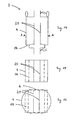
FIBC 2 can be seen. The reinforcingelement 20 ends with some distance D above the protruding bottom 18, and thestiffening elements 22 are inclined from theinner margins 26 towards their fixing point at the reinforcingelement 20. The top portion 6 is equipped with a filling device, and at the bottom of thebottom portion 8 is a discharging device. Fig. 9 shows a crosswise cross-sectional view along line A-A in Fig. 8, when the FIBC is empty. TheFIBC 2 is equipped with additionaledge connecting elements 28. These edge-connectingelements 28 also compriseopenings 24, so that bulk material filled into theFIBC 2 can flow into the edge compartments of theFIBC 2. The function of theedge connecting elements 28 can be seen in Fig. 10: there a crosswise cross-sectional view along line A-A in Fig. 9 is shown, when the FIBC is filled with bulk material. The bulk material tends to bulge out thesidewalls 4 of theFIBC 2, however, by the stiffening function of theedge connecting elements 28 the FIBC does not assume a more or less circular but more or less a square cross sectional form. The stiffened form is additionally supported by the function of the reinforcingelement 20, which additionally connectsopposite sidewalls 4. - Fig. 11 - 13 show nearly identical views upon an
FIBC 2 as shown in Fig. 8 - 10, but here without the additionaledge connecting elements 28. In Fig. 11 the bottom end of reinforcingelement 20 is reaching down into the space of the protrudingbottom 18. In Fig. 12 a cross-sectional view upon anempty FIBC 2 is shown, and in Fig. 13 theFIBC 2 is filled. In Fig. 13 it can be seen that anFIBC 2 assumes a shape of a kidney in a cross-sectional view, because the reinforcingelement 20 reinforces thesidewalls 4 in the area where the reinforcingelement 20 connects them. It is easy to understand, that due to the kidney-shape the centre of gravity of the filled FIBC is closer to the forklift, and due to the more rectangular cross-sectional form less hollow space occurs if a plurality ofsuch FIBCs 2 is loaded into a truck or container. It can also well be seen that the out bulging sides ofFIBC 2 are reaching over the lateral outer sides ofshoulders 14. This supports a safe handling of anFIBC 2 during transport with a forklift. - To increase the rigidity of an
FIBC 2 in thebottom portion 8, theshoulders 14 and/or thesidewalls 16 of the bottom portion may be armoured and/or reinforced by elements like the shapedparts 25 shown in Fig. 4a. The armours and reinforcements protect the outer surface of theFIBC 2 in the region of theshoulder 14 and thesidewalls 16 of the bottom portion against damages, which might be caused by the fork of the forklift. Because of the higher rigidity ofshoulders 14 and sidewalls 16, a risk free and quicker and more effective forklift handling is possible. - In Fig. 14 an
FIBC 2 is shown, which comprises two reinforcingelements 20. Of course, there may also be more than two reinforcingelements 20, if required or suitable for an application. The reinforcingelements 20 arranged in a vertical plane inside ofFIBC 2 and substantially parallel to each other. This can also be seen in Fig. 15, which is a cross-sectional view along line AA in Fig. 14. In Fig. 15 theFIBC 2 is empty, and the width of reinforcingelements 20 is substantially equal to the Iwidth of theparallel sidewalls 4 and thebottom portion 8. Fig. 16 shows the same view as Fig. 15, however, with anFIBC 2, which is filled with bulk material. As can be seen by the cross sectional view, thesidewalls 4, which are connected by the reinforcingelements 20, do not bulge out as much as it is shown in Fig. 13 for an application with a single reinforcingelement 20 in aFIBC 2. TheFIBC 2 with the two reinforcingelements 20 shows a form which comes closer to a generally rectangular shape. - Fig. 17 again shows an
FIBC 2 withsidewalls 4 and a reinforcingelement 20. As shown in Fig. 18, the reinforcingelement 20 is wider than the width of asidewall 4 andbottom portion 8. This results in a slack 30 in a width direction of the reinforcingelement 20, when theFIBC 2 is empty. If the reinforcingelement 20 has a wider width than asidewall 4, it may assume a form which has an approximately circular cross section, as shown in Fig. 19. By choosing suitable dimensions of one or more reinforcingelements 20, many different desired outer shapes of filledFIBCs 2 can be achieved.
Claims (10)
- FIBC (2) made of woven fabric or plastic film comprising a top portion (6), sidewalls (4) and a bottom portion (8), the bottom portion (8) having at least two longitudinal shoulders (14) on opposite sides of the FIBC (2) with a clearance to the ground, so that a fork of a forklift can be positioned underneath the shoulders (14), and further comprising flexible stiffening elements (22) inside the flexible intermediate bulk container (2), which are tension loaded when the FIBC (2) is filled with bulk material and thereby substantially maintain the shape of the shoulders (14) when the FIBC (2) is filled, characterized in, that a reinforcing element (20) is fixed to and connecting opposite surfaces of the sidewalls (4), and stiffening elements (22) are fixed to and connecting the reinforcing element (20) with the inner margins (26) of the shoulders (14).
- FIBC (2) according to claim 1, characterized in, that in an upstanding position of the FIBC (2) the horizontal plane of fixing of the stiffening elements (22) to the reinforcing element (20) is higher than the horizontal plane of fixing of the stiffening elements (22) to the inner margins (26) of the shoulders (14).
- FIBC (2) according to claim 1 or 2, characterized in, that the reinforcing element (20) consists of a panel made of flexible material.
- FIBC (2) according to any of the preceding claims, characterized in, that the reinforcing element (20) is arranged in a substantially vertical plane inside of the FIBC (2).
- FIBC (2) according to any of the preceding claims, characterized in, that the stiffening elements (22) are made of flexible material.
- FIBC (2) according to any of the preceding claims, characterized in, that the reinforcing element (20) and/or the stiffening elements (22) comprise openings (24) which allow bulk material filled into the FIBC (2) to flow, pour or trickle through them.
- FIBC (2) according to any of the preceding claims, characterized in, that the reinforcing element (20) and/or the stiffening elements (22) at least partially comprise an open-meshed net structure, which is inflexible upon pulling loads in at least one direction.
- FIBC (2) according to any of the preceding claims, characterized in, that the stiffening elements (22) are made by filaments, yarns (28), ropes, ribbons or tapes.
- FIBC (2) according to any of the preceding claims, characterized in, that the shoulders (14) and/or sidewalls (16) of the bottom portion (8) are reinforced.
- FIBC (2) according to any of the preceding claims, characterized in, that the reinforcing element (20) is arranged substantially in a parallel line towards the direction of the shoulders (14).
Priority Applications (1)
| Application Number | Priority Date | Filing Date | Title |
|---|---|---|---|
| EP03003656A EP1449792A1 (en) | 2003-02-18 | 2003-02-18 | Stabilized FIBC with reinforced element |
Applications Claiming Priority (1)
| Application Number | Priority Date | Filing Date | Title |
|---|---|---|---|
| EP03003656A EP1449792A1 (en) | 2003-02-18 | 2003-02-18 | Stabilized FIBC with reinforced element |
Publications (1)
| Publication Number | Publication Date |
|---|---|
| EP1449792A1 true EP1449792A1 (en) | 2004-08-25 |
Family
ID=32731530
Family Applications (1)
| Application Number | Title | Priority Date | Filing Date |
|---|---|---|---|
| EP03003656A Withdrawn EP1449792A1 (en) | 2003-02-18 | 2003-02-18 | Stabilized FIBC with reinforced element |
Country Status (1)
| Country | Link |
|---|---|
| EP (1) | EP1449792A1 (en) |
Citations (3)
| Publication number | Priority date | Publication date | Assignee | Title |
|---|---|---|---|---|
| EP0819620A1 (en) * | 1996-06-04 | 1998-01-21 | Natthi Cholsaipant | Flexible bulk bag |
| NL1010700C2 (en) * | 1998-12-02 | 2000-06-06 | Ihor Rotterdam B V | Box-shaped folding bag for loose material, has double skinned walls with reinforcing plates and cross connection strips to minimize side bulges |
| TR200102886A2 (en) * | 2001-10-08 | 2002-10-21 | Sunjüt Suni̇ Jüt Sanayi̇ Ve Ti̇c. A. Ş. | Mesh-based angles for bag compactness. |
-
2003
- 2003-02-18 EP EP03003656A patent/EP1449792A1/en not_active Withdrawn
Patent Citations (3)
| Publication number | Priority date | Publication date | Assignee | Title |
|---|---|---|---|---|
| EP0819620A1 (en) * | 1996-06-04 | 1998-01-21 | Natthi Cholsaipant | Flexible bulk bag |
| NL1010700C2 (en) * | 1998-12-02 | 2000-06-06 | Ihor Rotterdam B V | Box-shaped folding bag for loose material, has double skinned walls with reinforcing plates and cross connection strips to minimize side bulges |
| TR200102886A2 (en) * | 2001-10-08 | 2002-10-21 | Sunjüt Suni̇ Jüt Sanayi̇ Ve Ti̇c. A. Ş. | Mesh-based angles for bag compactness. |
Similar Documents
| Publication | Publication Date | Title |
|---|---|---|
| US4300608A (en) | Self-raising strap loop | |
| KR100188806B1 (en) | Package for transporting and storing bulk goods | |
| US4499599A (en) | Stackable flexible bulk container | |
| US6935500B1 (en) | Bulk bag with support system | |
| KR950000585B1 (en) | Cargo bag and method of forming same | |
| US8365912B2 (en) | Wire containment structure including container and bag | |
| US5076710A (en) | Spread strap flexible bulk container | |
| EP2785616B1 (en) | Container system comprising a "big bag", a support and a rope | |
| US5785175A (en) | Flexible bulk bag with improved base | |
| KR101874264B1 (en) | Container bag | |
| US6390675B1 (en) | Bag | |
| US20010027826A1 (en) | Flexible intermediate bulk container with fork lift guide | |
| EP2379426B1 (en) | Bag for bulk goods, and method for use in storing and/or transporting bulk goods | |
| US5203633A (en) | Spread strap flexible bulk container | |
| GB2429198A (en) | Lifting sleeves of a bulk bag | |
| US9446897B2 (en) | Bag for transporting and handling liquid or quasi liquid substances | |
| AU2009100871A4 (en) | Bulk bag | |
| EP1449792A1 (en) | Stabilized FIBC with reinforced element | |
| GB1581438A (en) | Containers | |
| JP2730557B2 (en) | Flexible bulk container | |
| US20050100248A1 (en) | Easy-to-transport sack | |
| EP0180379A2 (en) | Intermediate bulk containers | |
| KR100875255B1 (en) | Flowable Bulk Material Container | |
| US20030116460A1 (en) | System for stabilizing flexible bulk containers | |
| WO2009027989A1 (en) | Builder's bags |
Legal Events
| Date | Code | Title | Description |
|---|---|---|---|
| PUAI | Public reference made under article 153(3) epc to a published international application that has entered the european phase |
Free format text: ORIGINAL CODE: 0009012 |
|
| 17P | Request for examination filed |
Effective date: 20030329 |
|
| AK | Designated contracting states |
Kind code of ref document: A1 Designated state(s): AT BE BG CH CY CZ DE DK EE ES FI FR GB GR HU IE IT LI LU MC NL PT SE SI SK TR |
|
| AX | Request for extension of the european patent |
Extension state: AL LT LV MK RO |
|
| AKX | Designation fees paid | ||
| REG | Reference to a national code |
Ref country code: DE Ref legal event code: 8566 |
|
| STAA | Information on the status of an ep patent application or granted ep patent |
Free format text: STATUS: THE APPLICATION IS DEEMED TO BE WITHDRAWN |
|
| 18D | Application deemed to be withdrawn |
Effective date: 20050226 |