EP1449745A1 - Procédé et dispositif de guidage d'une remorque, véhicule équipé d'un tel dispositif - Google Patents
Procédé et dispositif de guidage d'une remorque, véhicule équipé d'un tel dispositif Download PDFInfo
- Publication number
- EP1449745A1 EP1449745A1 EP04370004A EP04370004A EP1449745A1 EP 1449745 A1 EP1449745 A1 EP 1449745A1 EP 04370004 A EP04370004 A EP 04370004A EP 04370004 A EP04370004 A EP 04370004A EP 1449745 A1 EP1449745 A1 EP 1449745A1
- Authority
- EP
- European Patent Office
- Prior art keywords
- axle
- steering
- towed
- towing
- angle
- Prior art date
- Legal status (The legal status is an assumption and is not a legal conclusion. Google has not performed a legal analysis and makes no representation as to the accuracy of the status listed.)
- Granted
Links
- 238000000034 method Methods 0.000 title claims abstract description 42
- 238000006073 displacement reaction Methods 0.000 claims abstract description 13
- 238000005070 sampling Methods 0.000 claims abstract description 12
- 238000012937 correction Methods 0.000 claims description 17
- 230000008878 coupling Effects 0.000 claims description 15
- 238000010168 coupling process Methods 0.000 claims description 15
- 238000005859 coupling reaction Methods 0.000 claims description 15
- 230000006870 function Effects 0.000 claims description 13
- 230000008569 process Effects 0.000 description 14
- 238000011282 treatment Methods 0.000 description 6
- 238000012546 transfer Methods 0.000 description 3
- 235000021183 entrée Nutrition 0.000 description 2
- 210000003608 fece Anatomy 0.000 description 2
- 239000010871 livestock manure Substances 0.000 description 2
- 239000007921 spray Substances 0.000 description 2
- 206010029216 Nervousness Diseases 0.000 description 1
- 230000002238 attenuated effect Effects 0.000 description 1
- 238000012550 audit Methods 0.000 description 1
- 238000013461 design Methods 0.000 description 1
- 238000010586 diagram Methods 0.000 description 1
- 201000010099 disease Diseases 0.000 description 1
- 208000037265 diseases, disorders, signs and symptoms Diseases 0.000 description 1
- 230000000694 effects Effects 0.000 description 1
- 238000005265 energy consumption Methods 0.000 description 1
- 239000012530 fluid Substances 0.000 description 1
- 230000000855 fungicidal effect Effects 0.000 description 1
- 239000000417 fungicide Substances 0.000 description 1
- 230000006872 improvement Effects 0.000 description 1
- 238000005259 measurement Methods 0.000 description 1
- 230000009467 reduction Effects 0.000 description 1
- 239000002002 slurry Substances 0.000 description 1
- 230000036962 time dependent Effects 0.000 description 1
Images

Classifications
-
- B—PERFORMING OPERATIONS; TRANSPORTING
- B62—LAND VEHICLES FOR TRAVELLING OTHERWISE THAN ON RAILS
- B62D—MOTOR VEHICLES; TRAILERS
- B62D13/00—Steering specially adapted for trailers
- B62D13/02—Steering specially adapted for trailers for centrally-pivoted axles
- B62D13/025—Steering specially adapted for trailers for centrally-pivoted axles the pivoted movement being initiated by the coupling means between tractor and trailer
-
- B—PERFORMING OPERATIONS; TRANSPORTING
- B62—LAND VEHICLES FOR TRAVELLING OTHERWISE THAN ON RAILS
- B62D—MOTOR VEHICLES; TRAILERS
- B62D13/00—Steering specially adapted for trailers
- B62D13/04—Steering specially adapted for trailers for individually-pivoted wheels
Definitions
- the present invention relates to a method and a device for guiding a steered trailer on the path followed by a towing vehicle.
- the invention also relates to the case of a vehicle whose front and rear axles are steered.
- the invention also relates to a vehicle provided with such a guide device.
- the invention was particularly developed in the context agricultural machinery. Indeed, during the passage in a field of a tractor to which a trailer is coupled, several problems can arise to pose.
- the spray is a fungicide
- the areas subcontracted risk of developing the disease against which a treatment had been planned and as a result of constituting a home likely to contaminate other plants once the intensity of treatment has attenuated.
- the signal leading to the deferral of the angle is generated either at intervals of constant time assuming a forward speed of the vehicle constant tractor, taking into account the forward speed and the chassis length. So, such systems lack precision, especially when the towing vehicle changes gear or even stops, because they are based on an indirect measure of the distance traveled.
- the object of the present invention is to provide a method and a device for guiding a trailer, as well as a vehicle equipped with such a device, which overcome the aforementioned drawbacks.
- An object of the present invention is to provide a method of guidance of a trailer such that it follows trace in trace the trajectory of the towing vehicle, as well as a device capable of implementing such a guiding process.
- Another object of the present invention is to provide a guide method and device flexible enough to be adapted to various types of couplings, in particular agricultural, field in which it is frequent to use successively different towed vehicles but the same towing vehicle.
- Another object of the present invention is to provide a guidance process which allows losses to be reduced both at the level of yield than in terms of the effectiveness of treatments applied to crops.
- Another object of the present invention is to provide a method and a trailer guide which take account of the changes in the direction of the towing vehicle within a turn.
- Another object of the invention is to propose a method and a guidance device independent of the coupling speed.
- the invention also relates to a vehicle equipped with such a device.
- the invention relates first of all to a method of guiding a RQ trailer fitted with at least one steering axle R along the path C described by a tractor vehicle VT equipped with at least one tractor axle T.
- the rear axle of the VT towing vehicle to which the RQ trailer is coupled.
- This axle is considered to be the towing axle T whether it is itself an axle engine or not of the towing vehicle.
- the trailer RQ is coupled to said axle at the coupling point 1.
- the tractor axle T is fixed, for example, i.e. that its wheels are not steered.
- the invention also aims to apply to a self-propelled vehicle with both front and rear axles directors.
- the RQ trailer includes a steering axle towed R and a drawbar 2 secured to the tractor axle T at level of the coupling point 1.
- the drawbar 2 has a length L varying from 3 to 8 m and for example from 3 to 5 m. This length is much greater than the distance between the coupling point 1 of the RQ trailer and the middle of the tractor axle T, the latter generally being between 30 and 80 cm, and for example between 30 and 50 cm. Also, in a first approximation, we consider that the distance separating the tractor axle T from the towed steering axle R is substantially equal to the length L of the drawbar 2.
- the problem that arises is the following: how to do so that a towed steering axle R goes through the same points as the tractor axle T. Indeed, when the tractor vehicle VT changes direction, several physical phenomena are involved in the RQ trailer.
- the traction force exerted by the towing vehicle VT at level of the towed steering axle R is broken down into a component longitudinal parallel to the plane of rotation of the wheels 4 in our example and a lateral component perpendicular to said plane of rotation of the wheels 4.
- a first phenomenon is due to the lateral component of said tensile force. This phenomenon tends to leave the trailer RQ of path C followed by the towing vehicle VT.
- Second phenomena tend to maintain the RQ trailer in its path. These are longitudinal friction, negligible compared to the lateral friction, of the gyroscopic effect of 4 wheels in rotation of the RQ trailer and the inertia of the RQ trailer.
- the problem is therefore to correct the axle trajectory towed director R of the trailer so that at all times whatever the path and speed of the hitch, consisting of the VT towing vehicle and the RQ trailer, the first phenomenon remains negligible compared to second phenomena.
- the proposed method therefore consists of iteratively calculating a steering angle ⁇ i to be applied to the towed steering axle R so that it moves along the path C of the tractor vehicle VT.
- the method according to the invention therefore comprises a step of sampling the path C of the tractor vehicle VT, intended to know close points, in comparison with the length of the coupling, of the path C followed by the tractor vehicle.
- the higher the sampling frequency the greater the precision of the process. In fact, this will make it possible to calculate and apply a steering angle ⁇ i which will be able to evolve almost continuously according to the changes in the direction taken by the tractor vehicle VT.
- the method also includes a step of recording the parameters relating to the positions C i of the tractor axle T sampled on the path C, with respect to the towed steering axle R. In fact, it is necessary to keep this information as long as the towed steering axle R has not reached one of these sampled positions C i of the tractor axle T.
- the last step of the method consists in applying at least partially said calculated steering angle ⁇ i , to the towed steering axle R. It is specified that the calculated steering angle ⁇ i is possibly partially applied because it is possible that this angle ⁇ i exceeds the deflection limits of the towed steering axle R. In this case, as we will see later, a new deflection angle ⁇ i can be calculated during a subsequent iteration of the process, so that gradually bring the trailer RQ back into the path of the towing vehicle VT.
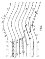
- the towed steering axle R is located at point C 0 and the towed axle T at point C 10 .
- the points of curve C located between the towed steering axle R and the towing axle T are numbered R 0 to R 10 .
- the points C i , T 0 (i) and R 1 (i-1) are merged, as shown by the first steps of the process illustrated by the curves in Figure 4.
- the curves (t 0 , t 1 , ..., t 23 ) correspond to successive iterations of the process according to the invention.
- the different positions occupied by the tractor axle T on the trajectory C are therefore designated either in a reference linked to the trajectory and independent of time, the points then being called C 1 , or in a movable reference linked to the towed steering axle R, time dependent, the points then being called R 0 , R 1 , etc.
- the parameters relating to the position C i of the tractor axle T on the path C relative to the towed steering axle R are either measured (front steering angle f i of the tractor vehicle and rear steering angle r i of the towed steering axle) are calculated (basic angle e i of trajectory correction).
- said elementary angles e i of trajectory correction are recorded in a shift register of FIFO type (first in, first out) to thus constitute a stack of said elementary angles e i of trajectory correction, which it suffices to sum for obtaining said steering angle ⁇ i to be applied to the towed steering axle R so that it moves on the trajectory C.
- a predetermined number N of positions C i previously recorded, thus located between the towing axle, are thus taken into account T and the towed steering axle R, since only the parameters relating to the points through which said towed steering axle R has not yet passed are kept in said shift register.
- the invention also relates to a device for guiding a RQ trailer fitted with at least one towed steering axle R, along the trajectory C described by a VT tractor vehicle equipped with at least one axle tractor T.
- the device comprises means for sampling the trajectory C of the towing vehicle as a function of the distance traveled by the coupling, to determine the movement of the vehicle tractor.
- a displacement sensor 5 which measures the distance traveled by the towed steering axle R.
- it is a sensor subject to the towed steering axle. R and cooperating with magnetic pads arranged at regular intervals on the periphery of a steering wheel 4 of the steering axle R.
- the device also comprises measurement means and means for recording parameters relating to the position C i of the tractor axle T on the path C relative to the towed steering axle R, as a function of the displacement.
- the sensors used are angular position sensors 6, 7, capable of measuring the front steering angle f i and rear r i .
- a front angular position sensor 6 is placed on the drawbar 2 of the trailer and measures the front steering angle f i formed between the fixed tractor axle T and the towed steering axle R, via a removable linkage system .
- a second angular position sensor 7 is placed at the rear of the chassis of the RQ trailer, on the fixed part of the towed steering axle R and measures the rear steering angle r formed between the drawbar 2 and the plane of rotation of the steering wheels 4 of the trailer RQ.
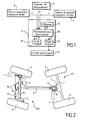
- the device comprises means for calculating the steering angle ⁇ i to be applied to the towed steering axle R so that it moves on the path C. It is for example an electronic computer 9 which receives information from the various sensors 5, 6 and 7.
- the device finally comprises control means able to apply at least partially said steering angle ⁇ i calculated to the towed steering axle R.
- the computer 9 comprises at minus a microprocessor 10, a memory 11 and a shift register 12.
- the microprocessor 10 is programmed to perform the operations of calculating said elementary trajectory correction angles e i and of the steering angle ⁇ i , to be applied to the towed steering axle R. It cooperates with said memory 11 and said shift register 12 by exchanging the information necessary for the calculations made.
- the microprocessor 10 also cooperates with a hydraulic circuit 14 by means of a device 13 for controlling the nervousness of the hydraulics, in order to apply said turning angle ⁇ i at least partially.
- Said computer 9 is for example equipped with components MOS-FET for hydraulic control.
- the steering angle ⁇ i is applied to said towed steering axle R by a hydraulic cylinder 15 cooperating with the steering wheels 4 to turn it, within the authorized turning limits.
- the device and the method according to the invention therefore make it possible to restore the front steering angle f i measured at the level of the towing axle T, when the towed steering axle R has reached the corresponding point, taking account of the fact that the front steering angle f i may have varied in the meantime.
- the steering angle ⁇ i to be applied to the towed steering axle R is therefore not applied directly but calculated as a function of a predetermined number N of positions C i previously recorded.
- the displacement sensor allows the system to be independent of speed. Even after a stop in a bend, followed by a restart, guiding the trailer RQ along the path C of the VT towing vehicle, possible.
- the invention also relates to a vehicle equipped with a device as described above, capable of implementing the method according to the invention.
- the tractor axle T may be the rear axle of an agricultural tractor, to which a trailer is coupled.
- the trailer it may be by example of a sprayer of phytosanitary products or other products of treatment, or a manure spreader.
- the traction is fitted with a joint located at a variable distance, 30 cm 3 m from the coupling point. This articulation makes it possible to apply an angle of steering at the trailer at the coupling point. In this case, we therefore have an articulated drawbar and not a steering axle, and the trailer remains steering.
Landscapes
- Engineering & Computer Science (AREA)
- Chemical & Material Sciences (AREA)
- Combustion & Propulsion (AREA)
- Transportation (AREA)
- Mechanical Engineering (AREA)
- Steering Control In Accordance With Driving Conditions (AREA)
- Guiding Agricultural Machines (AREA)
- Regulating Braking Force (AREA)
- Control Of Position, Course, Altitude, Or Attitude Of Moving Bodies (AREA)
- Power Steering Mechanism (AREA)
Abstract
Description
- on échantillonne la trajectoire du véhicule tracteur en fonction de la distance parcourue par l'attelage, constitué dudit véhicule tracteur et de ladite remorque, pour déterminer le déplacement du véhicule tracteur ;
- on enregistre successivement des paramètres relatifs à la position de l'essieu tracteur sur la trajectoire par rapport à l'essieu directeur remorqué, en fonction dudit déplacement ;
- on calcule pas à pas l'angle de braquage à appliquer à l'essieu directeur remorqué pour qu'il se déplace sur la trajectoire, en tenant compte d'un nombre prédéterminé de positions enregistrées précédemment ;
- on applique au moins partiellement ledit angle de braquage calculé audit essieu directeur remorqué.
- des moyens d'échantillonnage de la trajectoire du véhicule tracteur en fonction de la distance parcourue par l'attelage constitué du véhicule tracteur et de la remorque, pour déterminer le déplacement du véhicule tracteur ;
- des moyens de mesure et des moyens d'enregistrement de paramètres relatifs à la position de l'essieu tracteur sur la trajectoire par rapport à l'essieu directeur remorqué, en fonction dudit déplacement ;
- des moyens de calcul de l'angle de braquage à appliquer à l'essieu directeur remorqué pour qu'il se déplace sur la trajectoire ;
- des moyens de commande pour appliquer au moins partiellement ledit angle de braquage calculé à l'essieu directeur remorqué.
- la figure 1 est un diagramme représentant les moyens de l'invention selon une première variante ainsi que leurs relations,
- la figure 2 est une vue schématique de dessus d'un attelage équipé d'un dispositif conforme à l'invention,
- la figure 3 est une illustration schématique d'une boucle de fonctionnement d'un procédé conforme à l'invention,
- la figure 4 est une illustration schématique du déplacement d'un attelage selon l'invention le long de sa trajectoire, pour une bonne compréhension des notations utilisées dans la description.
- l'angle de braquage avant f0 formé entre l'essieu tracteur T et l'essieu directeur remorqué R, au point T ;
- l'angle de braquage arrière r0 formé entre le plan de rotation des roues directrices 4 et la barre de traction 2, au point R0.

- une entrée de sécurité, destinée à inhiber le système, par exemple pour les trajets sur route,
- des entrées de sélection du mode de fonctionnement, par exemple manuel ou automatique,
- un connecteur pour le paramétrage du dispositif à l'aide d'un ordinateur.
Claims (13)
- Procédé de guidage d'une remorque (RQ) équipée d'au moins un essieu directeur (R), le long de la trajectoire (C) décrite par un véhicule tracteur (VT) équipé d'au moins un essieu tracteur (T), caractérisé en ce que :on échantillonne la trajectoire (C) du véhicule tracteur (VT) en fonction de la distance parcourue par l'attelage, constitué dudit véhicule tracteur (VT) et de ladite remorque (RQ), pour déterminer le déplacement du véhicule tracteur (VT) ;on enregistre successivement des paramètres relatifs à la position (Ci) de l'essieu tracteur (T) sur la trajectoire (C) par rapport à l'essieu directeur remorqué (R), en fonction dudit déplacement ;on calcule, pas à pas, l'angle de braquage (αi) à appliquer à l'essieu directeur remorqué (R) pour qu'il se déplace sur la trajectoire (C), en tenant compte d'un nombre prédéterminé (N) de positions (Ci) enregistrées précédemment ;on applique au moins partiellement ledit angle de braquage (αi) calculé audit essieu directeur remorqué (R).
- Procédé selon la revendication 1, dans lequel on échantillonne ladite trajectoire et on enregistre lesdits paramètres à chaque fois que l'attelage a parcouru une distance prédéterminée (d).
- Procédé selon la revendication 1 ou 2, dans lequel lesdits paramètres sont mesurés et/ou calculés et comprennent l'angle de braquage avant (fi) du véhicule tracteur (VT) formé entre lesdits essieux tracteur (T) et directeur remorqué (R), ainsi que l'angle de braquage arrière (ri) de l'essieu directeur remorqué (R).
- Procédé selon la revendication 3, dans lequel lesdits paramètres comprennent en outre un angle élémentaire (ei) de correction de trajectoire qu'il faudra appliquer audit essieu directeur remorqué (R) lorsqu'il se trouvera à la position (Ci) de l'essieu tracteur (T).
- Procédé selon la revendication 4, dans lequel on enregistre ledit angle élémentaire (ei) de correction de trajectoire dans un registre à décalage (12).
- Procédé selon la revendication 4 ou 5, dans lequel on calcule ledit angle de braquage (αi) en sommant le nombre prédéterminé (N) d'angles élémentaires (ei) de correction de trajectoire correspondant aux positions enregistrées (Ci) situées entre l'essieu tracteur (T) et l'essieu directeur remorqué (R).
- Procédé selon l'une quelconque des revendications précédentes, dans lequel on calcule par interpolation, entre deux positions enregistrées successives (Ci, Ci+1), une position intercalaire pour améliorer la précision du guidage.
- Dispositif de guidage d'une remorque (RQ) équipée d'au moins un essieu directeur (R), le long de la trajectoire (C) décrite par un véhicule tracteur (VT) équipé d'au moins un essieu tracteur (T), comprenant :des moyens d'échantillonnage de la trajectoire (C) du véhicule tracteur (VT) en fonction de la distance parcourue par ledit attelage, pour déterminer le déplacement du véhicule tracteur (VT) ;des moyens de mesure et des moyens d'enregistrement des paramètres relatifs à la position (Ci) de l'essieu tracteur (T) sur la trajectoire (C) par rapport à l'essieu directeur remorqué (R), en fonction dudit déplacement ;des moyens de calcul de l'angle de braquage (αi) à appliquer à l'essieu directeur remorqué (R) pour qu'il se déplace sur la trajectoire (C) ;des moyens de commande pour appliquer au moins partiellement ledit angle de braquage (αi) calculé audit essieu directeur remorqué (R).
- Dispositif de guidage selon la revendication 8, dans lequel lesdits moyens d'échantillonnage se présentent sous la forme d'un capteur magnétique de déplacement (5).
- Dispositif selon la revendication 8 ou 9, dans lequel lesdits moyens de mesure des paramètres relatifs à la position (Ci) de l'essieu tracteur (T) sur la trajectoire (C) par rapport à l'essieu directeur remorqué (R) se présentent sous la forme de capteurs de position angulaire (6, 7) mesurant d'une part l'angle formé entre l'essieu directeur remorqué (R) et l'essieu tracteur (T) ou angle de braquage avant (fi), et d'autre part, l'angle de braquage arrière (ri).
- Dispositif selon l'une quelconque des revendications 8 à 10, comprenant un calculateur (9) intégrant des moyens d'enregistrement se présentant sous la forme d'une mémoire (11) et/ou d'un registre à décalage (12), des moyens de calcul se présentant sous la forme d'un micro-processeur (10), et des moyens de commande (13) d'un circuit hydraulique (14) destinés à appliquer au moins partiellement ledit angle de braquage (αi) calculé audit essieu directeur remorqué (R).
- Dispositif selon la revendication 11, dans lequel ledit circuit hydraulique (14) comprend un vérin hydraulique.
- Véhicule équipé d'un dispositif selon l'une quelconque des revendications 8 à 12.
Applications Claiming Priority (2)
| Application Number | Priority Date | Filing Date | Title |
|---|---|---|---|
| FR0302104 | 2003-02-20 | ||
| FR0302104A FR2851542B1 (fr) | 2003-02-20 | 2003-02-20 | Procede et dispositif de guidage d'une remorque, vehicule equipe d'un tel dispositif |
Publications (2)
| Publication Number | Publication Date |
|---|---|
| EP1449745A1 true EP1449745A1 (fr) | 2004-08-25 |
| EP1449745B1 EP1449745B1 (fr) | 2011-04-13 |
Family
ID=32732036
Family Applications (1)
| Application Number | Title | Priority Date | Filing Date |
|---|---|---|---|
| EP04370004A Expired - Lifetime EP1449745B1 (fr) | 2003-02-20 | 2004-02-20 | Procédé et dispositif de guidage d'une remorque, véhicule équipé d'un tel dispositif |
Country Status (6)
| Country | Link |
|---|---|
| EP (1) | EP1449745B1 (fr) |
| AT (1) | ATE505388T1 (fr) |
| DE (1) | DE602004032190D1 (fr) |
| DK (1) | DK1449745T3 (fr) |
| ES (1) | ES2364966T3 (fr) |
| FR (1) | FR2851542B1 (fr) |
Cited By (4)
| Publication number | Priority date | Publication date | Assignee | Title |
|---|---|---|---|---|
| US10085371B2 (en) | 2013-12-11 | 2018-10-02 | Cnh Industrial America Llc | Steerable rear axle on a field cultivator |
| WO2019012073A1 (fr) * | 2017-07-13 | 2019-01-17 | Rolf Meissner | Procédé permettant de maintenir la voie d'un véhicule à deux voies |
| FR3141428A1 (fr) | 2022-10-27 | 2024-05-03 | Sc Optima | Procédé et système de guidage d’essieu d’un véhicule tracté sur la trajectoire d’un véhicule tracteur |
| EP4397513A1 (fr) | 2022-10-27 | 2024-07-10 | Sc Optima | Procédé et système de guidage d'essieu d'un véhicule tracté sur la trajectoire d'un véhicule tracteur |
Citations (3)
| Publication number | Priority date | Publication date | Assignee | Title |
|---|---|---|---|---|
| US5329451A (en) | 1990-09-26 | 1994-07-12 | Nissan Diesel Motor Co., Ltd. | Steerable trailer and steering apparatus of combination vehicle |
| US5366059A (en) | 1992-08-27 | 1994-11-22 | Prairie Machine & Parts Mfg. Ltd. | Steering system for plurality of vehicles |
| US20010054524A1 (en) | 2000-05-16 | 2001-12-27 | Masters Nathan Eugene | Robotic vehicle that tracks the path of a lead vehicle |
-
2003
- 2003-02-20 FR FR0302104A patent/FR2851542B1/fr not_active Expired - Fee Related
-
2004
- 2004-02-20 AT AT04370004T patent/ATE505388T1/de not_active IP Right Cessation
- 2004-02-20 DE DE602004032190T patent/DE602004032190D1/de not_active Expired - Lifetime
- 2004-02-20 DK DK04370004.6T patent/DK1449745T3/da active
- 2004-02-20 EP EP04370004A patent/EP1449745B1/fr not_active Expired - Lifetime
- 2004-02-20 ES ES04370004T patent/ES2364966T3/es not_active Expired - Lifetime
Patent Citations (3)
| Publication number | Priority date | Publication date | Assignee | Title |
|---|---|---|---|---|
| US5329451A (en) | 1990-09-26 | 1994-07-12 | Nissan Diesel Motor Co., Ltd. | Steerable trailer and steering apparatus of combination vehicle |
| US5366059A (en) | 1992-08-27 | 1994-11-22 | Prairie Machine & Parts Mfg. Ltd. | Steering system for plurality of vehicles |
| US20010054524A1 (en) | 2000-05-16 | 2001-12-27 | Masters Nathan Eugene | Robotic vehicle that tracks the path of a lead vehicle |
Cited By (4)
| Publication number | Priority date | Publication date | Assignee | Title |
|---|---|---|---|---|
| US10085371B2 (en) | 2013-12-11 | 2018-10-02 | Cnh Industrial America Llc | Steerable rear axle on a field cultivator |
| WO2019012073A1 (fr) * | 2017-07-13 | 2019-01-17 | Rolf Meissner | Procédé permettant de maintenir la voie d'un véhicule à deux voies |
| FR3141428A1 (fr) | 2022-10-27 | 2024-05-03 | Sc Optima | Procédé et système de guidage d’essieu d’un véhicule tracté sur la trajectoire d’un véhicule tracteur |
| EP4397513A1 (fr) | 2022-10-27 | 2024-07-10 | Sc Optima | Procédé et système de guidage d'essieu d'un véhicule tracté sur la trajectoire d'un véhicule tracteur |
Also Published As
| Publication number | Publication date |
|---|---|
| ATE505388T1 (de) | 2011-04-15 |
| DK1449745T3 (da) | 2011-07-11 |
| DE602004032190D1 (de) | 2011-05-26 |
| ES2364966T3 (es) | 2011-09-19 |
| FR2851542A1 (fr) | 2004-08-27 |
| EP1449745B1 (fr) | 2011-04-13 |
| FR2851542B1 (fr) | 2006-03-17 |
Similar Documents
| Publication | Publication Date | Title |
|---|---|---|
| EP0598155B1 (fr) | Procédé et dispositif de commande du virage d'un véhicule chenillé ou à roues non directrices | |
| FR2530114A1 (fr) | Vehicule de travail roulant a marche automatique notamment une faucheuse ou analogue | |
| EP1449745B1 (fr) | Procédé et dispositif de guidage d'une remorque, véhicule équipé d'un tel dispositif | |
| EP4119428A1 (fr) | Ensemble roulant comprenant un engin tracteur et une remorque et procédé de pilotage d'un tel ensemble roulant | |
| WO2004052711A1 (fr) | Procede d’etablissement, dans un systeme de direction assistee electrique pour vehicule automobile, de la consigne du couple d’assistance | |
| EP0275744B1 (fr) | Dispositif de correction de l'angle d'attitude d'un véhicule automobile | |
| CA2907607A1 (fr) | Procede de reduction du risque de basculement d'un vehicule automoteur equipe d'un systeme de suspension pilotable | |
| FR2520185A1 (fr) | Dispositif de guidage automatique du deplacement d'un vehicule, notamment d'un vehicule tous terrains | |
| FR2589115A1 (fr) | Systeme de freinage a regulation du glissement pour un vehicule dont toutes les roues sont motrices | |
| EP3877821B1 (fr) | Procédé de détermination d'une trajectoire d'un véhicule autonome | |
| EP1934083B1 (fr) | Procede pour la detection de la tenue d'un volant de conduite d'une direction assistee electrique de vehicule automobile | |
| EP1088743A1 (fr) | Remorque à roues orientables | |
| EP1932747A1 (fr) | Procédé et dispositif de commande des roues directrices d'une remorque | |
| FR3043624A1 (fr) | Mesure du taux de patinage | |
| WO2023066610A1 (fr) | Procédé de détermination de la position angulaire d'un véhicule complexe à deux axes de rotation et système configuré pour mettre en œuvre un tel procédé | |
| FR3049815A1 (fr) | Vehicule tracteur autoguide | |
| EP1910154B1 (fr) | Procede d'aide au parcage en temps reel pour vehicule automobile et dispositif correspondant | |
| EP0655185B1 (fr) | Procédé et dispositif de contrÔle en effort et en position | |
| EP1234747B1 (fr) | Ensemble de direction assistée électrique pour véhicule et procédé de commande associé | |
| FR3141428A1 (fr) | Procédé et système de guidage d’essieu d’un véhicule tracté sur la trajectoire d’un véhicule tracteur | |
| EP4397513A1 (fr) | Procédé et système de guidage d'essieu d'un véhicule tracté sur la trajectoire d'un véhicule tracteur | |
| FR2969099A1 (fr) | Procede de controle d'une fonction d'aide au suivi d'une voie de circulation comprenant deux lignes | |
| EP1982887A1 (fr) | Procédé de contrôle de stabilité en boucle ouverte pour véhicule automobile | |
| FR2878403A1 (fr) | Dispositif d'aide au guidage d'un engin par rapport a au moins un rang d'une culture palissee | |
| EP1982888A1 (fr) | Procédé de contrôle de stabilité en boucle fermée pour véhicule automobile |
Legal Events
| Date | Code | Title | Description |
|---|---|---|---|
| PUAI | Public reference made under article 153(3) epc to a published international application that has entered the european phase |
Free format text: ORIGINAL CODE: 0009012 |
|
| AK | Designated contracting states |
Kind code of ref document: A1 Designated state(s): AT BE BG CH CY CZ DE DK EE ES FI FR GB GR HU IE IT LI LU MC NL PT RO SE SI SK TR |
|
| AX | Request for extension of the european patent |
Extension state: AL HR LT LV MK |
|
| RIN1 | Information on inventor provided before grant (corrected) |
Inventor name: NORODINE, MICHEL Inventor name: HOUSSARD, OLIVIER |
|
| 17P | Request for examination filed |
Effective date: 20050210 |
|
| AKX | Designation fees paid |
Designated state(s): AT BE BG CH CY CZ DE DK EE ES FI FR GB GR HU IE IT LI LU MC NL PT RO SE SI SK TR |
|
| 17Q | First examination report despatched |
Effective date: 20070712 |
|
| GRAP | Despatch of communication of intention to grant a patent |
Free format text: ORIGINAL CODE: EPIDOSNIGR1 |
|
| GRAJ | Information related to disapproval of communication of intention to grant by the applicant or resumption of examination proceedings by the epo deleted |
Free format text: ORIGINAL CODE: EPIDOSDIGR1 |
|
| GRAP | Despatch of communication of intention to grant a patent |
Free format text: ORIGINAL CODE: EPIDOSNIGR1 |
|
| GRAS | Grant fee paid |
Free format text: ORIGINAL CODE: EPIDOSNIGR3 |
|
| GRAA | (expected) grant |
Free format text: ORIGINAL CODE: 0009210 |
|
| AK | Designated contracting states |
Kind code of ref document: B1 Designated state(s): AT BE BG CH CY CZ DE DK EE ES FI FR GB GR HU IE IT LI LU MC NL PT RO SE SI SK TR |
|
| REG | Reference to a national code |
Ref country code: GB Ref legal event code: FG4D Free format text: NOT ENGLISH |
|
| REG | Reference to a national code |
Ref country code: CH Ref legal event code: EP |
|
| REG | Reference to a national code |
Ref country code: IE Ref legal event code: FG4D Free format text: LANGUAGE OF EP DOCUMENT: FRENCH |
|
| REF | Corresponds to: |
Ref document number: 602004032190 Country of ref document: DE Date of ref document: 20110526 Kind code of ref document: P |
|
| REG | Reference to a national code |
Ref country code: DE Ref legal event code: R096 Ref document number: 602004032190 Country of ref document: DE Effective date: 20110526 |
|
| REG | Reference to a national code |
Ref country code: DK Ref legal event code: T3 |
|
| REG | Reference to a national code |
Ref country code: NL Ref legal event code: T3 |
|
| REG | Reference to a national code |
Ref country code: ES Ref legal event code: FG2A Ref document number: 2364966 Country of ref document: ES Kind code of ref document: T3 Effective date: 20110919 |
|
| PG25 | Lapsed in a contracting state [announced via postgrant information from national office to epo] |
Ref country code: PT Free format text: LAPSE BECAUSE OF FAILURE TO SUBMIT A TRANSLATION OF THE DESCRIPTION OR TO PAY THE FEE WITHIN THE PRESCRIBED TIME-LIMIT Effective date: 20110816 Ref country code: SE Free format text: LAPSE BECAUSE OF FAILURE TO SUBMIT A TRANSLATION OF THE DESCRIPTION OR TO PAY THE FEE WITHIN THE PRESCRIBED TIME-LIMIT Effective date: 20110413 |
|
| REG | Reference to a national code |
Ref country code: IE Ref legal event code: FD4D |
|
| PG25 | Lapsed in a contracting state [announced via postgrant information from national office to epo] |
Ref country code: CY Free format text: LAPSE BECAUSE OF FAILURE TO SUBMIT A TRANSLATION OF THE DESCRIPTION OR TO PAY THE FEE WITHIN THE PRESCRIBED TIME-LIMIT Effective date: 20110413 Ref country code: FI Free format text: LAPSE BECAUSE OF FAILURE TO SUBMIT A TRANSLATION OF THE DESCRIPTION OR TO PAY THE FEE WITHIN THE PRESCRIBED TIME-LIMIT Effective date: 20110413 Ref country code: GR Free format text: LAPSE BECAUSE OF FAILURE TO SUBMIT A TRANSLATION OF THE DESCRIPTION OR TO PAY THE FEE WITHIN THE PRESCRIBED TIME-LIMIT Effective date: 20110714 Ref country code: AT Free format text: LAPSE BECAUSE OF FAILURE TO SUBMIT A TRANSLATION OF THE DESCRIPTION OR TO PAY THE FEE WITHIN THE PRESCRIBED TIME-LIMIT Effective date: 20110413 Ref country code: SI Free format text: LAPSE BECAUSE OF FAILURE TO SUBMIT A TRANSLATION OF THE DESCRIPTION OR TO PAY THE FEE WITHIN THE PRESCRIBED TIME-LIMIT Effective date: 20110413 |
|
| PG25 | Lapsed in a contracting state [announced via postgrant information from national office to epo] |
Ref country code: IE Free format text: LAPSE BECAUSE OF FAILURE TO SUBMIT A TRANSLATION OF THE DESCRIPTION OR TO PAY THE FEE WITHIN THE PRESCRIBED TIME-LIMIT Effective date: 20110413 Ref country code: CZ Free format text: LAPSE BECAUSE OF FAILURE TO SUBMIT A TRANSLATION OF THE DESCRIPTION OR TO PAY THE FEE WITHIN THE PRESCRIBED TIME-LIMIT Effective date: 20110413 Ref country code: EE Free format text: LAPSE BECAUSE OF FAILURE TO SUBMIT A TRANSLATION OF THE DESCRIPTION OR TO PAY THE FEE WITHIN THE PRESCRIBED TIME-LIMIT Effective date: 20110413 |
|
| PLBE | No opposition filed within time limit |
Free format text: ORIGINAL CODE: 0009261 |
|
| STAA | Information on the status of an ep patent application or granted ep patent |
Free format text: STATUS: NO OPPOSITION FILED WITHIN TIME LIMIT |
|
| PG25 | Lapsed in a contracting state [announced via postgrant information from national office to epo] |
Ref country code: SK Free format text: LAPSE BECAUSE OF FAILURE TO SUBMIT A TRANSLATION OF THE DESCRIPTION OR TO PAY THE FEE WITHIN THE PRESCRIBED TIME-LIMIT Effective date: 20110413 Ref country code: RO Free format text: LAPSE BECAUSE OF FAILURE TO SUBMIT A TRANSLATION OF THE DESCRIPTION OR TO PAY THE FEE WITHIN THE PRESCRIBED TIME-LIMIT Effective date: 20110413 |
|
| 26N | No opposition filed |
Effective date: 20120116 |
|
| REG | Reference to a national code |
Ref country code: DE Ref legal event code: R097 Ref document number: 602004032190 Country of ref document: DE Effective date: 20120116 |
|
| PG25 | Lapsed in a contracting state [announced via postgrant information from national office to epo] |
Ref country code: MC Free format text: LAPSE BECAUSE OF NON-PAYMENT OF DUE FEES Effective date: 20120229 |
|
| REG | Reference to a national code |
Ref country code: CH Ref legal event code: PL |
|
| PG25 | Lapsed in a contracting state [announced via postgrant information from national office to epo] |
Ref country code: LI Free format text: LAPSE BECAUSE OF NON-PAYMENT OF DUE FEES Effective date: 20120229 Ref country code: CH Free format text: LAPSE BECAUSE OF NON-PAYMENT OF DUE FEES Effective date: 20120229 |
|
| PG25 | Lapsed in a contracting state [announced via postgrant information from national office to epo] |
Ref country code: BG Free format text: LAPSE BECAUSE OF FAILURE TO SUBMIT A TRANSLATION OF THE DESCRIPTION OR TO PAY THE FEE WITHIN THE PRESCRIBED TIME-LIMIT Effective date: 20110713 |
|
| PG25 | Lapsed in a contracting state [announced via postgrant information from national office to epo] |
Ref country code: TR Free format text: LAPSE BECAUSE OF FAILURE TO SUBMIT A TRANSLATION OF THE DESCRIPTION OR TO PAY THE FEE WITHIN THE PRESCRIBED TIME-LIMIT Effective date: 20110413 |
|
| PG25 | Lapsed in a contracting state [announced via postgrant information from national office to epo] |
Ref country code: LU Free format text: LAPSE BECAUSE OF NON-PAYMENT OF DUE FEES Effective date: 20120220 |
|
| PG25 | Lapsed in a contracting state [announced via postgrant information from national office to epo] |
Ref country code: HU Free format text: LAPSE BECAUSE OF FAILURE TO SUBMIT A TRANSLATION OF THE DESCRIPTION OR TO PAY THE FEE WITHIN THE PRESCRIBED TIME-LIMIT Effective date: 20040220 |
|
| REG | Reference to a national code |
Ref country code: FR Ref legal event code: PLFP Year of fee payment: 13 |
|
| REG | Reference to a national code |
Ref country code: FR Ref legal event code: PLFP Year of fee payment: 14 |
|
| REG | Reference to a national code |
Ref country code: FR Ref legal event code: PLFP Year of fee payment: 15 |
|
| PGFP | Annual fee paid to national office [announced via postgrant information from national office to epo] |
Ref country code: NL Payment date: 20190225 Year of fee payment: 16 |
|
| PGFP | Annual fee paid to national office [announced via postgrant information from national office to epo] |
Ref country code: IT Payment date: 20200228 Year of fee payment: 17 Ref country code: DE Payment date: 20200221 Year of fee payment: 17 Ref country code: GB Payment date: 20200221 Year of fee payment: 17 |
|
| PGFP | Annual fee paid to national office [announced via postgrant information from national office to epo] |
Ref country code: BE Payment date: 20200221 Year of fee payment: 17 |
|
| PGFP | Annual fee paid to national office [announced via postgrant information from national office to epo] |
Ref country code: ES Payment date: 20200422 Year of fee payment: 17 |
|
| REG | Reference to a national code |
Ref country code: DK Ref legal event code: EBP Effective date: 20200229 |
|
| REG | Reference to a national code |
Ref country code: NL Ref legal event code: MM Effective date: 20200301 |
|
| PG25 | Lapsed in a contracting state [announced via postgrant information from national office to epo] |
Ref country code: NL Free format text: LAPSE BECAUSE OF NON-PAYMENT OF DUE FEES Effective date: 20200301 |
|
| PG25 | Lapsed in a contracting state [announced via postgrant information from national office to epo] |
Ref country code: DK Free format text: LAPSE BECAUSE OF NON-PAYMENT OF DUE FEES Effective date: 20200229 |
|
| REG | Reference to a national code |
Ref country code: DE Ref legal event code: R119 Ref document number: 602004032190 Country of ref document: DE |
|
| GBPC | Gb: european patent ceased through non-payment of renewal fee |
Effective date: 20210220 |
|
| REG | Reference to a national code |
Ref country code: BE Ref legal event code: MM Effective date: 20210228 |
|
| PG25 | Lapsed in a contracting state [announced via postgrant information from national office to epo] |
Ref country code: DE Free format text: LAPSE BECAUSE OF NON-PAYMENT OF DUE FEES Effective date: 20210901 Ref country code: GB Free format text: LAPSE BECAUSE OF NON-PAYMENT OF DUE FEES Effective date: 20210220 |
|
| PG25 | Lapsed in a contracting state [announced via postgrant information from national office to epo] |
Ref country code: IT Free format text: LAPSE BECAUSE OF NON-PAYMENT OF DUE FEES Effective date: 20210220 |
|
| REG | Reference to a national code |
Ref country code: ES Ref legal event code: FD2A Effective date: 20220513 |
|
| PG25 | Lapsed in a contracting state [announced via postgrant information from national office to epo] |
Ref country code: ES Free format text: LAPSE BECAUSE OF NON-PAYMENT OF DUE FEES Effective date: 20210221 Ref country code: BE Free format text: LAPSE BECAUSE OF NON-PAYMENT OF DUE FEES Effective date: 20210228 |
|
| PGFP | Annual fee paid to national office [announced via postgrant information from national office to epo] |
Ref country code: FR Payment date: 20230220 Year of fee payment: 20 |