EP1449680A1 - A tire having a composite belt structure - Google Patents
A tire having a composite belt structure Download PDFInfo
- Publication number
- EP1449680A1 EP1449680A1 EP04100581A EP04100581A EP1449680A1 EP 1449680 A1 EP1449680 A1 EP 1449680A1 EP 04100581 A EP04100581 A EP 04100581A EP 04100581 A EP04100581 A EP 04100581A EP 1449680 A1 EP1449680 A1 EP 1449680A1
- Authority
- EP
- European Patent Office
- Prior art keywords
- belt
- tire
- layers
- cords
- zigzag
- Prior art date
- Legal status (The legal status is an assumption and is not a legal conclusion. Google has not performed a legal analysis and makes no representation as to the accuracy of the status listed.)
- Granted
Links
- 239000002131 composite material Substances 0.000 title claims abstract description 7
- 230000003014 reinforcing effect Effects 0.000 claims abstract description 10
- 239000011324 bead Substances 0.000 description 13
- 239000004677 Nylon Substances 0.000 description 4
- 230000015572 biosynthetic process Effects 0.000 description 4
- 229920001778 nylon Polymers 0.000 description 4
- 238000000034 method Methods 0.000 description 3
- 238000004804 winding Methods 0.000 description 3
- 238000005452 bending Methods 0.000 description 2
- 238000010276 construction Methods 0.000 description 2
- 229920002302 Nylon 6,6 Polymers 0.000 description 1
- 230000001133 acceleration Effects 0.000 description 1
- 238000013459 approach Methods 0.000 description 1
- 238000005336 cracking Methods 0.000 description 1
- 230000003247 decreasing effect Effects 0.000 description 1
- 230000002349 favourable effect Effects 0.000 description 1
- 239000000463 material Substances 0.000 description 1
- 230000001737 promoting effect Effects 0.000 description 1
- 230000002787 reinforcement Effects 0.000 description 1
Images


Classifications
-
- B—PERFORMING OPERATIONS; TRANSPORTING
- B60—VEHICLES IN GENERAL
- B60C—VEHICLE TYRES; TYRE INFLATION; TYRE CHANGING; CONNECTING VALVES TO INFLATABLE ELASTIC BODIES IN GENERAL; DEVICES OR ARRANGEMENTS RELATED TO TYRES
- B60C9/00—Reinforcements or ply arrangement of pneumatic tyres
- B60C9/18—Structure or arrangement of belts or breakers, crown-reinforcing or cushioning layers
- B60C9/26—Folded plies
- B60C9/263—Folded plies further characterised by an endless zigzag configuration in at least one belt ply, i.e. no cut edge being present
-
- B—PERFORMING OPERATIONS; TRANSPORTING
- B60—VEHICLES IN GENERAL
- B60C—VEHICLE TYRES; TYRE INFLATION; TYRE CHANGING; CONNECTING VALVES TO INFLATABLE ELASTIC BODIES IN GENERAL; DEVICES OR ARRANGEMENTS RELATED TO TYRES
- B60C9/00—Reinforcements or ply arrangement of pneumatic tyres
- B60C9/18—Structure or arrangement of belts or breakers, crown-reinforcing or cushioning layers
- B60C9/20—Structure or arrangement of belts or breakers, crown-reinforcing or cushioning layers built-up from rubberised plies each having all cords arranged substantially parallel
- B60C9/22—Structure or arrangement of belts or breakers, crown-reinforcing or cushioning layers built-up from rubberised plies each having all cords arranged substantially parallel the plies being arranged with all cords disposed along the circumference of the tyre
- B60C9/2204—Structure or arrangement of belts or breakers, crown-reinforcing or cushioning layers built-up from rubberised plies each having all cords arranged substantially parallel the plies being arranged with all cords disposed along the circumference of the tyre obtained by circumferentially narrow strip winding
-
- Y—GENERAL TAGGING OF NEW TECHNOLOGICAL DEVELOPMENTS; GENERAL TAGGING OF CROSS-SECTIONAL TECHNOLOGIES SPANNING OVER SEVERAL SECTIONS OF THE IPC; TECHNICAL SUBJECTS COVERED BY FORMER USPC CROSS-REFERENCE ART COLLECTIONS [XRACs] AND DIGESTS
- Y10—TECHNICAL SUBJECTS COVERED BY FORMER USPC
- Y10T—TECHNICAL SUBJECTS COVERED BY FORMER US CLASSIFICATION
- Y10T152/00—Resilient tires and wheels
- Y10T152/10—Tires, resilient
- Y10T152/10495—Pneumatic tire or inner tube
- Y10T152/10765—Characterized by belt or breaker structure
- Y10T152/10783—Reinforcing plies made up from wound narrow ribbons
Definitions
- This invention relates to pneumatic tires having a carcass and a belt reinforcing structure, more particularly to high speed heavy load radial ply tires such as those used on aircraft.
- Pneumatic tires for high speed applications experience a high degree of flexure in the crown area of the tire as the tire enters and leaves the contact patch. This problem is particularly exacerbated on aircraft tires wherein the tires can reach speed of over 200 mph at takeoff and landing.
- the radially inner belt plies contained cords extending substantially in a zigzag path at a cord angle A of 5 degrees to 15 degrees in the circumferential direction with respect to the equatorial plane while being bent at both sides or lateral edges of the ply.
- Each of the outer belt plies contains cords having a cord angle B larger than the cord angle A of the radially inner belt plies.
- the invention relates to a pneumatic tire according to claim 1.
- the cords are folded or preferably bent to change direction across the crown of the carcass thus forming a zigzag cord path.
- At least two radially inner zigzag belt layers are positioned between the carcass and the at least one spirally wound belt layer.
- Each of the radially inner zigzag belt layers has cords wound at an inclination of 5 degrees to 30 degrees relative to the centerplane of the tire and extending in alternation to turnaround points at each lateral edge of the belt layers.
- the cords of the at least two radially inner spirally wound belt layers are wound from a single cord or from a group of 2 to 20 cords which continuously extend to form spirally wound belt layer and the at least two radially outer belt layers.
- the cords of the spirally wound belt layer in a single cord or a group of 2 to 20 cords may be continuously wound to form the at least two radially outer belt layers.
- the tire should have three belt layers, preferably five, as a minimum as measured at the tire's center.
- the tire is well suited for high speeds and large loads such as found in aircraft tires.
- Axial and “axially” mean lines or directions that are parallel to the axis of rotation of the tire.
- Cut belt or cut breaker reinforcing structure means at least two cut layers of plies of parallel cords, woven or unwoven, underlying the tread, unanchored to the bead, and having both left and right cord angles, preferably in the range from 10 degrees to 33 degrees with respect to the equatorial plane of the tire.
- “Bias ply tire” means a tire having a carcass with reinforcing cords in the carcass ply extending diagonally across the tire from bead core to bead core at a 25°-50° angle with respect to the equatorial plane of the tire. Cords run at opposite angles in alternate layers.
- Carcass means the tire structure apart from the belt structure, tread, undertread, and sidewall rubber over the plies, but including the beads.
- “Circumferential” means lines or directions extending along the perimeter of the surface of the annular tread perpendicular to the axial direction.
- Core means one of the reinforcement strands of which the plies in the tire are comprised.
- Equatorial plane means the plane perpendicular to the tire's axis of rotation and passing through the center of its tread.
- Ply means a continuous layer of rubber-coated parallel cords.
- Ring and radially mean directions radially toward or away from the axis of rotation of the tire.
- Ring-ply tire means a belted or circumferentially-restricted pneumatic tire in which the ply cords which extend from bead to bead are laid at cord angles, preferably between 65° and 90° with respect to the equatorial plane of the tire.
- Zerogzag belt reinforcing structure means at least two layers of cords or a ribbon of parallel cords having 2 to 20 cords in each ribbon and laid up in an alternating pattern extending at an angle between 5° and 30° between lateral edges of the belt layers.
- numeral 21 is a radial tire of the preferred embodiment of the invention, as shown, to be mounted onto an airplane, which comprises a pair of bead portions 23 each containing a bead core 22 embedded therein, a sidewall portion 24 extending substantially outward from each of the bead portions 23 in the radial direction of the tire, and a tread portion 25 of substantially cylindrical shape extending between radially outer ends of these sidewall portions 24.
- the tire 21 is reinforced with a carcass 31 toroidially extending from one of the bead portions 23 to the other bead portion 23.
- the carcass 31 is comprised of at least two carcass plies 32, e.g. six carcass plies 32 in the illustrated embodiment.
- each of these carcass plies 32 contains many nylon cords 33 such as nylon-6,6 cords extending substantially perpendicular to an equatorial plane E of the tire (i.e. extending in the radial direction of the tire).
- a tread rubber 36 is arranged on the outside of the carcass 31 in the radial direction.
- a belt 40 is arranged between the carcass 31 and the tread rubber 36 and is comprised of plural inner belt plies or layers 41 located near the carcass 31, i.e. two radially inner belt layers 41 in the illustrated embodiment and plural radially outer belt layers 42 located near to the tread rubber 36, i.e. two radially outer belt layers 42 in the illustrated embodiment. As shown in FIGS.
- each of the radially inner belt plies 41 is formed by providing a rubberized strip 43 of one or more cords 46, winding the strip 43 generally in the circumferential direction while being inclined to extend between side ends or lateral edges 44 and 45 of the layer forming a zigzag path and conducting such a winding many times while the strip 43 is shifted at approximately a width of the strip in the circumferential direction so as not to form a gap between the adjoining strips 43.
- the cords 46 extend substantially zigzag in the circumferential direction while changing the bending direction at a turnaround point at both ends 44, 45 and are substantially uniformly embedded in the first inner belt layer 41 over a full region of the first inner belt layer 41.
- the cords 46 lie one upon another, so that two first and second inner belt layers 41 are formed while crossing the cords 46 of these plies with each other.
- the radially outer belt layers 42 are made using the same method. Interposed between the inner layers 41 and outer layers 42 is at least one spirally wound layer 39 of cords 46, the cords being wound at an angle of plus or minus 5 degrees or less relative to the circumferential direction.
- the tire illustrated is a 42x17.0R18 with a 26 ply rating and the tire 21 has the belt composite reinforcing structure as shown in FIG. 9.
- the tire of FIG. 9 has two inner zigzag layers 41 and three spiral layers 39 and two outer zigzag layers 42.
- the cords 46 of the inner belt plies 41 cross with each other at a cord angle A of 5 degrees to 15 degrees with respect to the equatorial plane of the tire when the strip 43 is reciprocated at least once between both side ends 44 and 45 of the ply within every 360 degrees of the circumference as mentioned above.
- the widths of the inner belt layers 41 become narrower as the ply 41 is formed outward in the radial direction or approaches toward the tread rubber 36. Further, when the inner belt layers 41 is formed by winding the rubberized strip 43 containing plural cords 46 arranged in parallel with each other as mentioned above, a period for forming the ply layer 41 can be shortened and also the cord 46 arrangement can be made accurate. However, the strip 43 is bent at the side ends 44, 45 of the ply with a small radius of curvature R as shown in FIG. 5, so that a large compressive strain is produced in a cord 46 located at innermost side of the curvature R in the strip 43 to remain as a residual strain.
- the compressive strain produced in the cord 46 can be controlled to not exceed 25%. Therefore, when the inner belt layer 41 is formed by using the rubberized strip 43 containing plural nylon cords 46 therein, it is preferable that the value of R/W is not less than 2.0. In addition to the case where the strip 43 is bent at both side ends 44, 45 of the ply in form of an arc as shown in FIG.
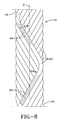
- the strip 43 may have a straight portion extending along the side end 44 (45) and an arc portion located at each end of the straight portion as shown in FIG. 6. Even in the latter case, it is favorable that the value of R/W in the arc portion is not less than 2.0. Furthermore, when the strip 43 is wound while being bent with a given radius of curvature R at both side ends 44, 45 of the ply, a zone 47 of a bent triangle formed by overlapping three strips 43 with each other at a half width of the strip as shown in FIG. 7 is repeatedly created in these bent portions or in the vicinity of both side ends 44, 45 of the ply in the circumferential direction as shown in FIG. 5. These two strips 43 are usually overlapped with each other by each forming operation.
- the width changes in accordance with the position in the circumferential direction continuously in the circumferential direction.
- these laminated bent portions 47 turn inward in the axial direction as they are formed outward in the radial direction as shown in FIG. 7 because the widths of the inner belt layers 41 become narrower toward the outside in the radial direction as previously mentioned.
- the outer end in widthwise direction of the middle strip 43c sandwiched between upper and lower strips 43a and 43b overlaps with the zone 47 located inward from the middle strip 43c in the radial direction as shown in FIG. 7.
- the middle layers 39 of the composite belt structure 40 are spirally wound around the radially inner belt layers 41. As shown in FIG. 7 the spirally wound layer 39 extends completely across the two radially inner belt layers 41 and ends at 39a just inside the end 41 a.
- the cords 46 within each strip 39 extend at an angle of 5 degrees or less relative to the circumferential equatorial plane. As shown four cords are in each strip.
- the strips 41, 39,and 42 could be wound using a single cord 46 or plural cords 46 in a strip or ribbon having plural cords in the range of 2 to 20 cords within each strip.
- the strips 43 had a width W, W being 0.5 inches. It is believed preferable that the strip width W should be 1.0 inch or less to facilitate bending to form the zigzag paths of the inner and outer layers 41, 42.
- the layers 41, 39, and 42 are all formed from a continuous strip 43 that simply forms the at least two radially zigzag layers 41 and then continues to form the at least one spirally wound layer 39 and then continues on to form the at least two radially outer layers 42.
- the spirally wound layers 39 could be formed as a separate layer from a strip 43.
- This alternative method of construction permits the cords 46 to be of different size or even of different materials from the zigzag layers 41 and 42.
- the circumferential layer 39 by being placed between the zigzag layers 41 and 42 greatly reduces the circumferential growth of the tire 21 in not only the belt edges 44, 45 but in particular the crown area of the tread 36.
- the spirally wound circumferential layer 39 by resisting growth in the crown area of the tire, greatly reduces the cut propensity due to foreign object damage and also reduces tread cracking under the grooves. This means the tire's high speed durability is greatly enhanced and its load carrying capacity is even greater. Aircraft tires using multiple layers of only zigzag ribbons on radial plied carcasses showed excellent lateral cornering forces. This is a common problem of radial tires using spiral layers in combination with cut belt layers which show poor cornering or lateral force characteristics. Unfortunately, using all zigzag layered belt layers have poor load and durability issues that are inferior to the more conventional spiral belt layers in combination with cut belt layers.
- the present invention has greatly improved the durability of the zigzag type belt construction while achieving very good lateral force characteristics as illustrated in FIG. 10.
- the all zigzag belted tire A is slightly better than the tire B of the present invention which is shown better than the spiral belt with a combination of cut belt layers of tire C in terms of lateral forces. Nevertheless the all zigzag belted tire A cannot carry the required double overloads at inflation whereas the tire B of the present invention easily meets these load requirements.
- the tire of the present invention may have a nylon overlay directly below the tread. This overlay is used to assist in retreading.
Abstract
Description
- This invention relates to pneumatic tires having a carcass and a belt reinforcing structure, more particularly to high speed heavy load radial ply tires such as those used on aircraft.
- Pneumatic tires for high speed applications experience a high degree of flexure in the crown area of the tire as the tire enters and leaves the contact patch. This problem is particularly exacerbated on aircraft tires wherein the tires can reach speed of over 200 mph at takeoff and landing.
- When a tire spins at very high speeds the crown area tends to grow in dimension due to the high angular accelerations and velocity tending to pull the tread area radially outwardly. Counteracting these forces is the load of the vehicle which is only supported in the small area of the tire known as the contact patch.
- US-A- 5,427,167, suggests the use of a large number of belt plies piled on top of one another was prone to cracks inside the belt layers which tended to grow outwardly causing a cut peel off and scattering of the belt and the tread during running. Therefore, such a belt ply is not used for airplanes. Watanabe found that zigzag belt layers could be piled onto the radially inner belt layers if the cord angles progressively increased from the inner belt layers toward the outer belt layers. In other words the radially inner belt plies contained cords extending substantially in a zigzag path at a cord angle A of 5 degrees to 15 degrees in the circumferential direction with respect to the equatorial plane while being bent at both sides or lateral edges of the ply. Each of the outer belt plies contains cords having a cord angle B larger than the cord angle A of the radially inner belt plies.
- The invention relates to a pneumatic tire according to claim 1. Preferably, at each turnaround point the cords are folded or preferably bent to change direction across the crown of the carcass thus forming a zigzag cord path.
- In a preferred embodiment at least two radially inner zigzag belt layers are positioned between the carcass and the at least one spirally wound belt layer. Each of the radially inner zigzag belt layers has cords wound at an inclination of 5 degrees to 30 degrees relative to the centerplane of the tire and extending in alternation to turnaround points at each lateral edge of the belt layers.
- The cords of the at least two radially inner spirally wound belt layers are wound from a single cord or from a group of 2 to 20 cords which continuously extend to form spirally wound belt layer and the at least two radially outer belt layers.
- Alternatively, the cords of the spirally wound belt layer in a single cord or a group of 2 to 20 cords may be continuously wound to form the at least two radially outer belt layers.
- As described above the tire should have three belt layers, preferably five, as a minimum as measured at the tire's center.
- The tire is well suited for high speeds and large loads such as found in aircraft tires.
- "Axial" and "axially" mean lines or directions that are parallel to the axis of rotation of the tire.
- "Cut belt or cut breaker reinforcing structure" means at least two cut layers of plies of parallel cords, woven or unwoven, underlying the tread, unanchored to the bead, and having both left and right cord angles, preferably in the range from 10 degrees to 33 degrees with respect to the equatorial plane of the tire.
- "Bias ply tire" means a tire having a carcass with reinforcing cords in the carcass ply extending diagonally across the tire from bead core to bead core at a 25°-50° angle with respect to the equatorial plane of the tire. Cords run at opposite angles in alternate layers.
- "Carcass" means the tire structure apart from the belt structure, tread, undertread, and sidewall rubber over the plies, but including the beads.
- "Circumferential" means lines or directions extending along the perimeter of the surface of the annular tread perpendicular to the axial direction.
- "Cord" means one of the reinforcement strands of which the plies in the tire are comprised.
- "Equatorial plane (EP)" means the plane perpendicular to the tire's axis of rotation and passing through the center of its tread.
- "Ply" means a continuous layer of rubber-coated parallel cords.
- "Radial" and "radially" mean directions radially toward or away from the axis of rotation of the tire.
- "Radial-ply tire" means a belted or circumferentially-restricted pneumatic tire in which the ply cords which extend from bead to bead are laid at cord angles, preferably between 65° and 90° with respect to the equatorial plane of the tire.
- "Zigzag belt reinforcing structure" means at least two layers of cords or a ribbon of parallel cords having 2 to 20 cords in each ribbon and laid up in an alternating pattern extending at an angle between 5° and 30° between lateral edges of the belt layers.
-
- FIG. 1 us a schematically section view of a first embodiment of the tire according to the invention;
- FIG. 2 is a partially cutaway top view of the tire shown in FIG. 1;
- FIG. 3 is a schematically perspective view of an inner or outer zigzag belt layer in the middle of the formation;
- FIG. 4 is a schematically developed view of the inner or outer zigzag belt layers in the middle of the formation;
- FIG. 5 is an enlargedly developed view of the inner or outer zigzag belt layers in the vicinity of the side end of the ply in the middle of the formation;
- FIG. 6 is an enlargedly developed view of another embodiment of the inner belt layer in the vicinity of the side end of the ply in the middle of the formation;
- FIG. 7 is a schematically enlarged section view of the composite belt layers in the vicinity of side end portions of these plies;
- FIG. 8 is a schematically developed view of the inner layer located at an outmost side;
- FIG. 9 is a schematically enlarged section view of another embodiment of plural inner belt plies in the vicinity of side end portions of these plies;
- FIG. 10 compares three tires A, B and C with regard to their lateral force characteristics.
-
- In FIGS. 1 and 2,
numeral 21 is a radial tire of the preferred embodiment of the invention, as shown, to be mounted onto an airplane, which comprises a pair ofbead portions 23 each containing abead core 22 embedded therein, asidewall portion 24 extending substantially outward from each of thebead portions 23 in the radial direction of the tire, and atread portion 25 of substantially cylindrical shape extending between radially outer ends of thesesidewall portions 24. Furthermore, thetire 21 is reinforced with acarcass 31 toroidially extending from one of thebead portions 23 to theother bead portion 23. Thecarcass 31 is comprised of at least twocarcass plies 32, e.g. sixcarcass plies 32 in the illustrated embodiment. Among these carcass plies 32, four inner plies are wound around thebead core 22 from inside of the tire toward outside thereof to form turnup portions, while two outer plies are extended downward to thebead core 22 along the outside of the turnup portion of theinner carcass ply 32. Each of thesecarcass plies 32 containsmany nylon cords 33 such as nylon-6,6 cords extending substantially perpendicular to an equatorial plane E of the tire (i.e. extending in the radial direction of the tire). Atread rubber 36 is arranged on the outside of thecarcass 31 in the radial direction. - A
belt 40 is arranged between thecarcass 31 and thetread rubber 36 and is comprised of plural inner belt plies orlayers 41 located near thecarcass 31, i.e. two radiallyinner belt layers 41 in the illustrated embodiment and plural radiallyouter belt layers 42 located near to thetread rubber 36, i.e. two radiallyouter belt layers 42 in the illustrated embodiment. As shown in FIGS. 3 and 8, each of the radiallyinner belt plies 41 is formed by providing arubberized strip 43 of one ormore cords 46, winding thestrip 43 generally in the circumferential direction while being inclined to extend between side ends orlateral edges strip 43 is shifted at approximately a width of the strip in the circumferential direction so as not to form a gap between theadjoining strips 43. As a result, thecords 46 extend substantially zigzag in the circumferential direction while changing the bending direction at a turnaround point at bothends inner belt layer 41 over a full region of the firstinner belt layer 41. Moreover, it is intended to form the radiallyinner belt layer 41 by the above method, thecords 46 lie one upon another, so that two first and secondinner belt layers 41 are formed while crossing thecords 46 of these plies with each other. Similarly the radiallyouter belt layers 42 are made using the same method. Interposed between theinner layers 41 andouter layers 42 is at least one spirallywound layer 39 ofcords 46, the cords being wound at an angle of plus or minus 5 degrees or less relative to the circumferential direction. - In the pneumatic radial tire for airplanes, there are various sizes, the tire illustrated is a 42x17.0R18 with a 26 ply rating and the
tire 21 has the belt composite reinforcing structure as shown in FIG. 9. As shown the tire of FIG. 9 has twoinner zigzag layers 41 and threespiral layers 39 and twoouter zigzag layers 42. In any such tire size, thecords 46 of the inner belt plies 41 cross with each other at a cord angle A of 5 degrees to 15 degrees with respect to the equatorial plane of the tire when thestrip 43 is reciprocated at least once between bothside ends - In the illustrated embodiment, the widths of the
inner belt layers 41 become narrower as theply 41 is formed outward in the radial direction or approaches toward thetread rubber 36. Further, when theinner belt layers 41 is formed by winding therubberized strip 43 containingplural cords 46 arranged in parallel with each other as mentioned above, a period for forming theply layer 41 can be shortened and also thecord 46 arrangement can be made accurate. However, thestrip 43 is bent at theside ends cord 46 located at innermost side of the curvature R in thestrip 43 to remain as a residual strain. When thecord 46 is nylon cord, if the compressive strain exceeds 25%, there is a fear of promoting the cord fatigue. However, when a ratio of R/W (R is a radius of curvature (mm) of thestrip 43 at the side ends 44, 45 of the layer, and W is a width of the strip 43) is not less than 2.0 as shown in FIG. 6, the compressive strain produced in thecord 46 can be controlled to not exceed 25%. Therefore, when theinner belt layer 41 is formed by using therubberized strip 43 containingplural nylon cords 46 therein, it is preferable that the value of R/W is not less than 2.0. In addition to the case where thestrip 43 is bent at both side ends 44, 45 of the ply in form of an arc as shown in FIG. 5, thestrip 43 may have a straight portion extending along the side end 44 (45) and an arc portion located at each end of the straight portion as shown in FIG. 6. Even in the latter case, it is favorable that the value of R/W in the arc portion is not less than 2.0. Furthermore, when thestrip 43 is wound while being bent with a given radius of curvature R at both side ends 44, 45 of the ply, azone 47 of a bent triangle formed by overlapping threestrips 43 with each other at a half width of the strip as shown in FIG. 7 is repeatedly created in these bent portions or in the vicinity of both side ends 44, 45 of the ply in the circumferential direction as shown in FIG. 5. These twostrips 43 are usually overlapped with each other by each forming operation. The width changes in accordance with the position in the circumferential direction continuously in the circumferential direction. Moreover, these laminatedbent portions 47 turn inward in the axial direction as they are formed outward in the radial direction as shown in FIG. 7 because the widths of the inner belt layers 41 become narrower toward the outside in the radial direction as previously mentioned. In thebent portion 47, the outer end in widthwise direction of the middle strip 43c sandwiched between upper and lower strips 43a and 43b overlaps with thezone 47 located inward from the middle strip 43c in the radial direction as shown in FIG. 7. When thebelt 40 is constructed with these inner belt layers 41, the total number of belt layers or plies can be decreased while maintaining total strength but reducing the weight and also the occurrence of standing wave during the running at high speed can be prevented. - The middle layers 39 of the
composite belt structure 40 are spirally wound around the radially inner belt layers 41. As shown in FIG. 7 thespirally wound layer 39 extends completely across the two radially inner belt layers 41 and ends at 39a just inside the end 41 a. Thecords 46 within eachstrip 39 extend at an angle of 5 degrees or less relative to the circumferential equatorial plane. As shown four cords are in each strip. In practice thestrips single cord 46 orplural cords 46 in a strip or ribbon having plural cords in the range of 2 to 20 cords within each strip. In theexemplary tire 21 of the size 42x17.0R18 strips 43 having 8 cords perstrip 42 were used. Thestrips 43 had a width W, W being 0.5 inches. It is believed preferable that the strip width W should be 1.0 inch or less to facilitate bending to form the zigzag paths of the inner andouter layers - In the most preferred embodiment the
layers continuous strip 43 that simply forms the at least two radially zigzag layers 41 and then continues to form the at least onespirally wound layer 39 and then continues on to form the at least two radially outer layers 42. Alternatively, the spirally wound layers 39 could be formed as a separate layer from astrip 43. This alternative method of construction permits thecords 46 to be of different size or even of different materials from the zigzag layers 41 and 42. What is believed to be the most important aspect of the invention is thecircumferential layer 39 by being placed between thezigzag layers tire 21 in not only the belt edges 44, 45 but in particular the crown area of thetread 36. The spirally woundcircumferential layer 39, by resisting growth in the crown area of the tire, greatly reduces the cut propensity due to foreign object damage and also reduces tread cracking under the grooves. This means the tire's high speed durability is greatly enhanced and its load carrying capacity is even greater. Aircraft tires using multiple layers of only zigzag ribbons on radial plied carcasses showed excellent lateral cornering forces. This is a common problem of radial tires using spiral layers in combination with cut belt layers which show poor cornering or lateral force characteristics. Unfortunately, using all zigzag layered belt layers have poor load and durability issues that are inferior to the more conventional spiral belt layers in combination with cut belt layers. - The present invention has greatly improved the durability of the zigzag type belt construction while achieving very good lateral force characteristics as illustrated in FIG. 10. The all zigzag belted tire A is slightly better than the tire B of the present invention which is shown better than the spiral belt with a combination of cut belt layers of tire C in terms of lateral forces. Nevertheless the all zigzag belted tire A cannot carry the required double overloads at inflation whereas the tire B of the present invention easily meets these load requirements.
- The tire of the present invention may have a nylon overlay directly below the tread. This overlay is used to assist in retreading.
Claims (5)
- A pneumatic tire (21) having a carcass (31) and a belt reinforcing structure, the belt reinforcing structure (40) being characterized by a composite belt structure (40) of cord reinforced layers (39, 41, 42) including at least two radially outer zigzag belt layers (42), each outer zigzag belt layer (42) having cords (46) inclined at 5 to 30 degrees relative to the centerplane of the tire extending in alternation to turnaround points at each lateral edge (44, 45), and at least one spirally wound belt layer (39) having cords (46) wound spirally at an inclination of 5 degrees or less relative to the tire's centerplane and located radially inward of and preferably adjacent to the at least two radially outer zigzag belt layers (42).
- The pneumatic tire of claim 1, the belt reinforcing structure further characterized by at least two radially inner zigzag belt layers (41), the radially inner zigzag belt layers (41) being positioned between the carcass (31) and the at least one spiral wound belt layer (39), at each radially inner zigzag belt layer (41) having cords (46) wound in alternation at an inclination of 5 degrees to 30 degrees relative to the centerplane of the tire (21) to turnaround points at each lateral edge (44, 45) of the belt layer.
- The pneumatic tire of claim 1 or 2, wherein the cords (46) of the radially inner spirally wound belt layers (41) are wound from a single cord or from a group of 2 to 20 cords which continuously extend to form the at least two radially outer zigzag belt layers (42).
- The pneumatic tire of at least one of the preceding claims, wherein the composite belt structure has five belt layers, two radially inner zigzag belt layers (41), one spirally wound belt layer (39) and two radially outer zigzag belt layers (42).
- The pneumatic tire of at least one of the preceding claims, the tire being an aircraft tire having one or more radial plies (32) in the carcass (31).
Applications Claiming Priority (2)
| Application Number | Priority Date | Filing Date | Title |
|---|---|---|---|
| US373384 | 2003-02-24 | ||
| US10/373,384 US20040163748A1 (en) | 2003-02-24 | 2003-02-24 | Tire having a composite belt structure |
Publications (2)
| Publication Number | Publication Date |
|---|---|
| EP1449680A1 true EP1449680A1 (en) | 2004-08-25 |
| EP1449680B1 EP1449680B1 (en) | 2007-03-21 |
Family
ID=32736483
Family Applications (1)
| Application Number | Title | Priority Date | Filing Date |
|---|---|---|---|
| EP04100581A Expired - Fee Related EP1449680B1 (en) | 2003-02-24 | 2004-02-13 | A tire having a composite belt structure |
Country Status (5)
| Country | Link |
|---|---|
| US (2) | US20040163748A1 (en) |
| EP (1) | EP1449680B1 (en) |
| JP (1) | JP4564268B2 (en) |
| BR (1) | BRPI0400143A (en) |
| DE (1) | DE602004005367T2 (en) |
Cited By (8)
| Publication number | Priority date | Publication date | Assignee | Title |
|---|---|---|---|---|
| EP1806241A1 (en) * | 2006-01-04 | 2007-07-11 | Bridgestone Corporation | Radial tire for airplane |
| EP1806242A1 (en) * | 2006-01-04 | 2007-07-11 | Bridgestone Corporation | Radial tire for airplane |
| EP2394822A1 (en) * | 2010-06-11 | 2011-12-14 | The Goodyear Tire & Rubber Company | Tire comprising a zigzag belt reinforcing structure, in particular a reduced weight aircraft tire |
| FR2976217A1 (en) * | 2011-06-13 | 2012-12-14 | Goodyear Tire & Rubber | PNEUMATIC BANDAGE |
| FR2976218A1 (en) * | 2011-06-13 | 2012-12-14 | Goodyear Tire & Rubber | PNEUMATIC BANDAGE |
| WO2015071152A1 (en) * | 2013-11-15 | 2015-05-21 | Compagnie Generale Des Etablissements Michelin | Crown reinforcement for an aircraft tyre |
| US9272577B2 (en) | 2011-06-13 | 2016-03-01 | The Goodyear Tire & Rubber Company | Aircraft radial tire |
| EP3643530A4 (en) * | 2017-06-19 | 2021-01-13 | Bridgestone Corporation | Bead core, production method therefor, and pneumatic tire |
Families Citing this family (13)
| Publication number | Priority date | Publication date | Assignee | Title |
|---|---|---|---|---|
| US7360571B2 (en) * | 2003-09-16 | 2008-04-22 | The Goodyear Tire & Rubber Company | Pneumatic tire with composite belt structure |
| JP4959182B2 (en) * | 2005-12-12 | 2012-06-20 | 株式会社ブリヂストン | Aircraft radial tire |
| JP4810384B2 (en) * | 2006-09-29 | 2011-11-09 | 株式会社ブリヂストン | Pneumatic tire |
| US20080105352A1 (en) * | 2006-11-03 | 2008-05-08 | Kiyoshi Ueyoko | Reduced weight aircraft tire |
| US20100154964A1 (en) * | 2008-12-19 | 2010-06-24 | Francois Pierre Charles Gerard Georges | Pneumatic tire |
| US20100154965A1 (en) * | 2008-12-19 | 2010-06-24 | Roland Willibrord Krier | Offset zigzag belt structure for a pneumatic tire |
| US8578988B2 (en) * | 2010-08-20 | 2013-11-12 | The Goodyear Tire & Rubber Company | Reduced weight aircraft tire |
| FR3012077B1 (en) * | 2013-10-23 | 2016-12-09 | Michelin & Cie | PNEUMATIC SUMMIT FRAME FOR AIRCRAFT |
| JP6501113B2 (en) * | 2015-05-13 | 2019-04-17 | 株式会社ブリヂストン | Pneumatic tire |
| JP6458120B2 (en) * | 2017-11-17 | 2019-01-23 | 住友ゴム工業株式会社 | Pneumatic tires for motorcycles |
| JP6750639B2 (en) * | 2018-01-30 | 2020-09-02 | 住友ゴム工業株式会社 | Pneumatic tire |
| JP7129900B2 (en) * | 2018-12-21 | 2022-09-02 | 株式会社ブリヂストン | Aircraft pneumatic tire |
| JP2022081052A (en) * | 2020-11-19 | 2022-05-31 | 株式会社ブリヂストン | Pneumatic tire for aircraft |
Citations (3)
| Publication number | Priority date | Publication date | Assignee | Title |
|---|---|---|---|---|
| EP0425318A2 (en) * | 1989-10-27 | 1991-05-02 | Bridgestone Corporation | Pneumatic radial tires |
| JPH09226313A (en) * | 1996-02-23 | 1997-09-02 | Bridgestone Corp | Pneumatic radial tire |
| EP0887208A2 (en) * | 1997-06-27 | 1998-12-30 | Sumitomo Rubber Industries Ltd. | Pneumatic tyre |
Family Cites Families (28)
| Publication number | Priority date | Publication date | Assignee | Title |
|---|---|---|---|---|
| US3608605A (en) * | 1969-05-28 | 1971-09-28 | William G Cole | Pneumatic tire construction |
| US4838966A (en) * | 1986-11-12 | 1989-06-13 | The Armstrong Rubber Co. | Woven endless tire reinforcing belt and method for producing same |
| GB2201925B (en) * | 1987-03-12 | 1991-02-27 | Dunlop Ltd | Radial ply tyre |
| US5271445A (en) * | 1988-09-19 | 1993-12-21 | Bridgestone Corporation | Pneumatic tire including wave-shaped cords or filaments |
| JP3009670B2 (en) * | 1988-09-19 | 2000-02-14 | 株式会社ブリヂストン | Pneumatic tires for passenger cars |
| ES2068901T3 (en) * | 1988-10-14 | 1995-05-01 | Bridgestone Corp | RADIAL TIRE FOR PLANE. |
| JP2842558B2 (en) * | 1990-05-02 | 1999-01-06 | 住友ゴム工業 株式会社 | Radial tires for motorcycles |
| US5223061A (en) * | 1990-10-01 | 1993-06-29 | The Goodyear Tire & Rubber Company | Belt structure for a radial pneumatic tire, including spirally wound strips reinforced by cords comprising aramid yarns |
| JPH04173404A (en) * | 1990-11-06 | 1992-06-22 | Sumitomo Rubber Ind Ltd | Pneumatic tire |
| JP3126516B2 (en) * | 1991-10-29 | 2001-01-22 | 株式会社ブリヂストン | Aircraft radial tires |
| JP2628939B2 (en) * | 1991-02-28 | 1997-07-09 | 住友ゴム工業株式会社 | Pneumatic tire |
| CA2063340A1 (en) * | 1991-11-12 | 1993-05-13 | Mahmoud Cherif Assaad | Biased pneumatic tire having a belt structure with six annular layers |
| JP3061322B2 (en) | 1992-03-26 | 2000-07-10 | 住友ゴム工業株式会社 | Radial tire for aircraft |
| JP3556712B2 (en) * | 1994-09-19 | 2004-08-25 | 株式会社ブリヂストン | Pneumatic tire |
| JPH08156513A (en) | 1994-12-09 | 1996-06-18 | Bridgestone Corp | Pneumatic radial tire |
| US5683543A (en) * | 1995-03-29 | 1997-11-04 | The Yokohama Rubber Co., Ltd. | Pneumatic radial tire with zigzag organic fiber cored belt layer |
| US5730814A (en) * | 1995-05-15 | 1998-03-24 | The Yokohama Rubber Co., Ltd. | Pneumatic radial tire with zigzag steel cord belt layer |
| EP0875402A4 (en) * | 1996-07-25 | 2001-03-14 | Yokohama Rubber Co Ltd | Pneumatic radial tire |
| FR2757799B1 (en) * | 1996-12-27 | 1999-02-05 | Michelin & Cie | SUMMIT FRAME FOR AIRCRAFT TIRES |
| JPH1134609A (en) * | 1997-05-23 | 1999-02-09 | Yokohama Rubber Co Ltd:The | Pneumatic radial tire |
| JP3615028B2 (en) * | 1997-10-09 | 2005-01-26 | 株式会社ブリヂストン | Pneumatic tire for ultra high speed and high load |
| JP3837219B2 (en) * | 1997-11-12 | 2006-10-25 | 横浜ゴム株式会社 | Pneumatic radial tire |
| US6708747B1 (en) * | 1998-08-19 | 2004-03-23 | Bridgestone Corporation | Pneumatic radial tires |
| EP1712376B1 (en) * | 1999-07-07 | 2009-12-16 | Sumtiomo Rubber Industries Ltd | Pneumatic tyre |
| JP2002211208A (en) * | 2000-11-17 | 2002-07-31 | Yokohama Rubber Co Ltd:The | Pneumatic radial tire for aircraft |
| JP2003062991A (en) * | 2001-08-23 | 2003-03-05 | Seiko Epson Corp | Ink-jet recording head and production method therefor |
| JP4424989B2 (en) * | 2002-01-24 | 2010-03-03 | 株式会社ブリヂストン | Pneumatic tire and manufacturing method thereof |
| US7360571B2 (en) * | 2003-09-16 | 2008-04-22 | The Goodyear Tire & Rubber Company | Pneumatic tire with composite belt structure |
-
2003
- 2003-02-24 US US10/373,384 patent/US20040163748A1/en not_active Abandoned
-
2004
- 2004-02-12 BR BR0400143-5A patent/BRPI0400143A/en not_active IP Right Cessation
- 2004-02-13 DE DE602004005367T patent/DE602004005367T2/en not_active Expired - Lifetime
- 2004-02-13 EP EP04100581A patent/EP1449680B1/en not_active Expired - Fee Related
- 2004-02-24 JP JP2004047962A patent/JP4564268B2/en not_active Expired - Fee Related
-
2005
- 2005-04-11 US US11/103,110 patent/US7789120B2/en not_active Expired - Fee Related
Patent Citations (3)
| Publication number | Priority date | Publication date | Assignee | Title |
|---|---|---|---|---|
| EP0425318A2 (en) * | 1989-10-27 | 1991-05-02 | Bridgestone Corporation | Pneumatic radial tires |
| JPH09226313A (en) * | 1996-02-23 | 1997-09-02 | Bridgestone Corp | Pneumatic radial tire |
| EP0887208A2 (en) * | 1997-06-27 | 1998-12-30 | Sumitomo Rubber Industries Ltd. | Pneumatic tyre |
Non-Patent Citations (1)
| Title |
|---|
| PATENT ABSTRACTS OF JAPAN vol. 1998, no. 01 30 January 1998 (1998-01-30) * |
Cited By (20)
| Publication number | Priority date | Publication date | Assignee | Title |
|---|---|---|---|---|
| EP1806241A1 (en) * | 2006-01-04 | 2007-07-11 | Bridgestone Corporation | Radial tire for airplane |
| EP1806242A1 (en) * | 2006-01-04 | 2007-07-11 | Bridgestone Corporation | Radial tire for airplane |
| US7798189B2 (en) | 2006-01-04 | 2010-09-21 | Bridgestone Corporation | Radial tire for airplane with zigzag belt cord having specified heat shrinkage stress |
| US7882878B2 (en) | 2006-01-04 | 2011-02-08 | Bridgestone Corporation | Radial tire for airplane |
| EP2394822A1 (en) * | 2010-06-11 | 2011-12-14 | The Goodyear Tire & Rubber Company | Tire comprising a zigzag belt reinforcing structure, in particular a reduced weight aircraft tire |
| CN102275466A (en) * | 2010-06-11 | 2011-12-14 | 固特异轮胎和橡胶公司 | Aircraft tire with reduced weight |
| US20110303336A1 (en) * | 2010-06-11 | 2011-12-15 | Kiyoshi Ueyoko | Reduced weight aircraft tire |
| US9346321B2 (en) * | 2010-06-11 | 2016-05-24 | The Goodyear Tire & Rubber Company | Reduced weight aircraft tire |
| GB2492868A (en) * | 2011-06-13 | 2013-01-16 | Goodyear Tire & Rubber | Pneumatic tyre |
| CN102825980A (en) * | 2011-06-13 | 2012-12-19 | 固特异轮胎和橡胶公司 | Reduced weight aircraft tire |
| FR2976218A1 (en) * | 2011-06-13 | 2012-12-14 | Goodyear Tire & Rubber | PNEUMATIC BANDAGE |
| GB2495167A (en) * | 2011-06-13 | 2013-04-03 | Goodyear Tire & Rubber | Pneumatic tyre |
| GB2492868B (en) * | 2011-06-13 | 2013-10-02 | Goodyear Tire & Rubber | Pneumatic tyre |
| GB2495167B (en) * | 2011-06-13 | 2014-10-01 | Goodyear Tire & Rubber | Pneumatic tyre |
| US9272577B2 (en) | 2011-06-13 | 2016-03-01 | The Goodyear Tire & Rubber Company | Aircraft radial tire |
| FR2976217A1 (en) * | 2011-06-13 | 2012-12-14 | Goodyear Tire & Rubber | PNEUMATIC BANDAGE |
| WO2015071152A1 (en) * | 2013-11-15 | 2015-05-21 | Compagnie Generale Des Etablissements Michelin | Crown reinforcement for an aircraft tyre |
| FR3013259A1 (en) * | 2013-11-15 | 2015-05-22 | Michelin & Cie | TOP REINFORCEMENT FOR AIR TIRE |
| US10589573B2 (en) | 2013-11-15 | 2020-03-17 | Compagnie Generale Des Etablissements Michelin | Crown reinforcement for an aircraft tire |
| EP3643530A4 (en) * | 2017-06-19 | 2021-01-13 | Bridgestone Corporation | Bead core, production method therefor, and pneumatic tire |
Also Published As
| Publication number | Publication date |
|---|---|
| EP1449680B1 (en) | 2007-03-21 |
| JP4564268B2 (en) | 2010-10-20 |
| DE602004005367T2 (en) | 2007-12-06 |
| US7789120B2 (en) | 2010-09-07 |
| BRPI0400143A (en) | 2004-12-28 |
| JP2004256097A (en) | 2004-09-16 |
| US20060000536A1 (en) | 2006-01-05 |
| US20040163748A1 (en) | 2004-08-26 |
| DE602004005367D1 (en) | 2007-05-03 |
Similar Documents
| Publication | Publication Date | Title |
|---|---|---|
| US7789120B2 (en) | Tire having a composite belt structure | |
| US7360571B2 (en) | Pneumatic tire with composite belt structure | |
| US20080105352A1 (en) | Reduced weight aircraft tire | |
| US9346321B2 (en) | Reduced weight aircraft tire | |
| EP2420396B1 (en) | Pneumatic tire | |
| US11186122B2 (en) | Reduced weight aircraft tire | |
| US20160200147A1 (en) | Reduced weight aircraft tire | |
| US11827064B2 (en) | Reduced weight aircraft tire | |
| US20100154961A1 (en) | Pneumatic tire | |
| EP2977229B1 (en) | Reduced weight aircraft tire | |
| US8919403B2 (en) | Pneumatic tire | |
| US8967213B2 (en) | Aircraft tire | |
| EP3290232B1 (en) | Tire with low weight and high burst strength | |
| US20120312440A1 (en) | Reduced weight aircraft tire | |
| EP2202094B1 (en) | Offset zigzag belt structure for a pneumatic tire | |
| US20210380229A1 (en) | Reduced weight aircraft tire | |
| GB2507196A (en) | Pneumatic tyre |
Legal Events
| Date | Code | Title | Description |
|---|---|---|---|
| PUAI | Public reference made under article 153(3) epc to a published international application that has entered the european phase |
Free format text: ORIGINAL CODE: 0009012 |
|
| AK | Designated contracting states |
Kind code of ref document: A1 Designated state(s): AT BE BG CH CY CZ DE DK EE ES FI FR GB GR HU IE IT LI LU MC NL PT RO SE SI SK TR |
|
| AX | Request for extension of the european patent |
Extension state: AL LT LV MK |
|
| 17P | Request for examination filed |
Effective date: 20050225 |
|
| AKX | Designation fees paid |
Designated state(s): DE FR GB |
|
| RBV | Designated contracting states (corrected) |
Designated state(s): DE FR GB |
|
| GRAP | Despatch of communication of intention to grant a patent |
Free format text: ORIGINAL CODE: EPIDOSNIGR1 |
|
| GRAS | Grant fee paid |
Free format text: ORIGINAL CODE: EPIDOSNIGR3 |
|
| GRAA | (expected) grant |
Free format text: ORIGINAL CODE: 0009210 |
|
| AK | Designated contracting states |
Kind code of ref document: B1 Designated state(s): DE FR GB |
|
| REG | Reference to a national code |
Ref country code: GB Ref legal event code: FG4D |
|
| REF | Corresponds to: |
Ref document number: 602004005367 Country of ref document: DE Date of ref document: 20070503 Kind code of ref document: P |
|
| ET | Fr: translation filed | ||
| PLBE | No opposition filed within time limit |
Free format text: ORIGINAL CODE: 0009261 |
|
| STAA | Information on the status of an ep patent application or granted ep patent |
Free format text: STATUS: NO OPPOSITION FILED WITHIN TIME LIMIT |
|
| 26N | No opposition filed |
Effective date: 20071227 |
|
| REG | Reference to a national code |
Ref country code: FR Ref legal event code: PLFP Year of fee payment: 13 |
|
| REG | Reference to a national code |
Ref country code: FR Ref legal event code: PLFP Year of fee payment: 14 |
|
| REG | Reference to a national code |
Ref country code: FR Ref legal event code: PLFP Year of fee payment: 15 |
|
| PGFP | Annual fee paid to national office [announced via postgrant information from national office to epo] |
Ref country code: GB Payment date: 20210203 Year of fee payment: 18 Ref country code: DE Payment date: 20210202 Year of fee payment: 18 |
|
| PGFP | Annual fee paid to national office [announced via postgrant information from national office to epo] |
Ref country code: FR Payment date: 20211217 Year of fee payment: 19 |
|
| REG | Reference to a national code |
Ref country code: DE Ref legal event code: R119 Ref document number: 602004005367 Country of ref document: DE |
|
| GBPC | Gb: european patent ceased through non-payment of renewal fee |
Effective date: 20220213 |
|
| PG25 | Lapsed in a contracting state [announced via postgrant information from national office to epo] |
Ref country code: GB Free format text: LAPSE BECAUSE OF NON-PAYMENT OF DUE FEES Effective date: 20220213 Ref country code: DE Free format text: LAPSE BECAUSE OF NON-PAYMENT OF DUE FEES Effective date: 20220901 |
|
| PG25 | Lapsed in a contracting state [announced via postgrant information from national office to epo] |
Ref country code: FR Free format text: LAPSE BECAUSE OF NON-PAYMENT OF DUE FEES Effective date: 20230228 |