EP1449647A1 - Shock absorbing material - Google Patents
Shock absorbing material Download PDFInfo
- Publication number
- EP1449647A1 EP1449647A1 EP02802373A EP02802373A EP1449647A1 EP 1449647 A1 EP1449647 A1 EP 1449647A1 EP 02802373 A EP02802373 A EP 02802373A EP 02802373 A EP02802373 A EP 02802373A EP 1449647 A1 EP1449647 A1 EP 1449647A1
- Authority
- EP
- European Patent Office
- Prior art keywords
- impact absorbing
- absorbing member
- impact
- rigid polyurethane
- thickness
- Prior art date
- Legal status (The legal status is an assumption and is not a legal conclusion. Google has not performed a legal analysis and makes no representation as to the accuracy of the status listed.)
- Granted
Links
Images

Classifications
-
- B—PERFORMING OPERATIONS; TRANSPORTING
- B32—LAYERED PRODUCTS
- B32B—LAYERED PRODUCTS, i.e. PRODUCTS BUILT-UP OF STRATA OF FLAT OR NON-FLAT, e.g. CELLULAR OR HONEYCOMB, FORM
- B32B27/00—Layered products comprising a layer of synthetic resin
- B32B27/06—Layered products comprising a layer of synthetic resin as the main or only constituent of a layer, which is next to another layer of the same or of a different material
- B32B27/08—Layered products comprising a layer of synthetic resin as the main or only constituent of a layer, which is next to another layer of the same or of a different material of synthetic resin
-
- B—PERFORMING OPERATIONS; TRANSPORTING
- B32—LAYERED PRODUCTS
- B32B—LAYERED PRODUCTS, i.e. PRODUCTS BUILT-UP OF STRATA OF FLAT OR NON-FLAT, e.g. CELLULAR OR HONEYCOMB, FORM
- B32B27/00—Layered products comprising a layer of synthetic resin
- B32B27/40—Layered products comprising a layer of synthetic resin comprising polyurethanes
-
- B—PERFORMING OPERATIONS; TRANSPORTING
- B32—LAYERED PRODUCTS
- B32B—LAYERED PRODUCTS, i.e. PRODUCTS BUILT-UP OF STRATA OF FLAT OR NON-FLAT, e.g. CELLULAR OR HONEYCOMB, FORM
- B32B5/00—Layered products characterised by the non- homogeneity or physical structure, i.e. comprising a fibrous, filamentary, particulate or foam layer; Layered products characterised by having a layer differing constitutionally or physically in different parts
- B32B5/18—Layered products characterised by the non- homogeneity or physical structure, i.e. comprising a fibrous, filamentary, particulate or foam layer; Layered products characterised by having a layer differing constitutionally or physically in different parts characterised by features of a layer of foamed material
-
- B—PERFORMING OPERATIONS; TRANSPORTING
- B60—VEHICLES IN GENERAL
- B60R—VEHICLES, VEHICLE FITTINGS, OR VEHICLE PARTS, NOT OTHERWISE PROVIDED FOR
- B60R21/00—Arrangements or fittings on vehicles for protecting or preventing injuries to occupants or pedestrians in case of accidents or other traffic risks
- B60R21/02—Occupant safety arrangements or fittings, e.g. crash pads
- B60R21/04—Padded linings for the vehicle interior ; Energy absorbing structures associated with padded or non-padded linings
-
- B—PERFORMING OPERATIONS; TRANSPORTING
- B60—VEHICLES IN GENERAL
- B60R—VEHICLES, VEHICLE FITTINGS, OR VEHICLE PARTS, NOT OTHERWISE PROVIDED FOR
- B60R21/00—Arrangements or fittings on vehicles for protecting or preventing injuries to occupants or pedestrians in case of accidents or other traffic risks
- B60R2021/003—Arrangements or fittings on vehicles for protecting or preventing injuries to occupants or pedestrians in case of accidents or other traffic risks characterised by occupant or pedestian
- B60R2021/0039—Body parts of the occupant or pedestrian affected by the accident
- B60R2021/0048—Head
-
- B—PERFORMING OPERATIONS; TRANSPORTING
- B60—VEHICLES IN GENERAL
- B60R—VEHICLES, VEHICLE FITTINGS, OR VEHICLE PARTS, NOT OTHERWISE PROVIDED FOR
- B60R21/00—Arrangements or fittings on vehicles for protecting or preventing injuries to occupants or pedestrians in case of accidents or other traffic risks
- B60R21/02—Occupant safety arrangements or fittings, e.g. crash pads
- B60R21/04—Padded linings for the vehicle interior ; Energy absorbing structures associated with padded or non-padded linings
- B60R2021/0442—Padded linings for the vehicle interior ; Energy absorbing structures associated with padded or non-padded linings associated with the roof panel
Definitions
- the present invention relates to an impact absorbing member.
- an impact absorbing member is provided.
- Examples of conventional impact absorbing member include a rigid polyurethane foam, a polyolefin foam, a resin formed body having a rib on one surface thereof, and a pressed product made of steel or the like.
- An impact absorbing member made of rigid polyurethane foam has the following advantages: excellent impact absorbing characteristics; low temperature dependence of the impact energy absorbing characteristics; impact absorbing characteristics which is relatively stable against a variety of plunging angle of a free motion head dummy (FMH); easy adjustment of the impact absorbing characteristics; and good economical efficiency because of relatively low cost.
- the ideal impact absorbing characteristics as impact absorbing member is as follows: its load reaches a certain value (certain acceleration) at an initial stage of the compression and, after that, keeps the certain value (certain acceleration), that is, has an F-S waveform (load-stroke waveform) in which the load (F) rises promptly relative to the stroke (S) and, after that, the load (F) keeps substantially constant with transition of the stroke (S).
- the impact absorbing member made of rigid polyurethane foam exhibits the F-S waveform nearly equal to the ideal F-S waveform when impact is applied evenly to the whole surface thereof, such as when compressed between two flat plates.
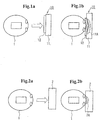
- the rigid polyurethane foam is a buckling (brittle) member. Therefore, as shown in Figs. 2a, 2b, when a spherical body such as a free motion head dummy (FMH) 1 collides with and compress an impact absorbing member 2 made of rigid polyurethane foam, stress is locally concentrated on the impact absorbing member 2 and the FMH 1 dents into the impact absorbing member. In this case, the impact energy thereby absorbed is small. That is, as shown in Fig. 2b, when the conventional head protecting member 2 of rigid polyurethane foam is pressed by the FMH 1 at a small area as shown by broken lines 2A, only a portion including the area shown by the broken lines 2A and just around the area contributes to the impact energy absorption.
- FMH free motion head dummy
- An impact absorbing member according to the present invention is an impact absorbing member comprising a body made of a rigid polyurethane foam and a surface member which has a rigidity higher than that of the body and is disposed on the impact receiving surface of the body.
- Fig. 1a shows an impact absorbing member 10 according to an embodiment of the present invention.
- the impact absorbing member 10 comprises a body 11 made of a rigid polyurethane foam and a surface member 12 which has a rigidity higher than that of the body 11 and is disposed on one surface of the body 11.
- the load generated in the initial stage of collision with an FMH 1 is dispersed on a wider area by the surface member 12. Therefore, as shown in Fig. 1b, the compressive load in the initial stage acts on a wider area of the body 11.
- the body 11 is squashed to deform not only a collided portion where the FMH 1 collides but also a wider area (shown by broken lines 11A) around the collided portion. Accordingly, even with a short stroke, large impact energy can be absorbed.
- a desired load-stroke curve is imparted to the impact absorbing member.
- the body 11 is preferably in a shape of a plate including a flat plate and a curved plate.
- the rigid polyurethane foam forming the body 11 preferably has a compressive stress at 50% relative deformation of about 0.25 MPa or more, particularly from about 0.25 MPa to 2 MPa, more particularly from about 0.25 MPa to 1.6 MPa.
- the rigid polyurethane foam preferably has a density of from 40 kg/m 3 to 200 kg/m 3 , particularly from 40 kg/m 3 to 140 kg/m 3 .
- the surface member 12 has a rigidity higher than that of the rigid polyurethane foam of the body 11 and preferably has a flexural modulus from 2 MPa to 1500 MPa.
- the surface member 12 is preferably made of synthetic resin, metal, alloy, glass, ceramics, and the like.
- the synthetic resin include polypropylene, polyethylene and polyethylene terephthalate.
- the metal include iron, aluminum, and copper.
- the alloy include iron-based alloy, aluminum-based alloy, and copper-based alloy.
- the surface member may be made of paper material, such as corrugated cardboard, or wood. In this case, however, a large thickness is required.
- the body When the impact absorbing member is a head protecting member, the body preferably has a thickness of 10-80 mm, particularly 10-40 mm, more particularly 20-30 mm. When the thickness of the body is less than 10 mm, enough stroke is not obtained so as not to exhibit enough impact energy absorbing efficiency. On the other hand, when the thickness of the body exceeds 80 mm, the impact absorbing member is bulky. Even the impact absorbing member comprising a body having a small thickness in a range from 10 mm to 25 mm can exhibit excellent impact energy absorbing efficiency.
- the surface member is in a shape of a plate preferably having a thickness of about 0.5-5 mm.
- the impact absorbing member comprises the surface member having a thickness of less than 0.5 mm, the impact absorbing property is insufficient even if the surface member is made of a high-rigid material such as ceramics.
- the surface member has a thickness exceeding 5mm, the rigidity of the impact absorbing member should be too large.
- the surface member 12 and the body 11 may be united together.
- the surface member 12 may be united with the body 11 with adhesive or pressure-sensitive adhesive.
- the surface material 12 may be disposed in a mold for forming the body and the body may be formed and integrated with the surface member by insert molding. The surface member may not be connected with the body.
- the surface member preferably covers substantially the whole area of the impact receiving surface of the body. Substantially the whole area of the surface of the body 11 may be covered by one piece of the surface member or a plurality of small surface members. Each of the small surface members may be in circular form of 25 mm or more in diameter or a square form of 25 mm or more on a side. The minimum size is preferably 25 mm ,, or more.
- the body and the surface member are suitably combined by selecting the properties of the rigid polyurethane foam forming the body and the size (thickness) of the body, and the material, the properties, and the size (thickness) of the surface member according to the purpose, thereby providing an impact absorbing member having desired excellent impact energy absorbing efficiency.
- the impact absorbing member of the present invention can be used suitably as, but not limited to, a head protecting member which is installed to vehicle body or an interior trim such as a head liner and a garnish.
- a body made of a rigid polyurethane foam having the following properties and size and a surface member made of polypropylene having the following properties and size were prepared and were united together by bonding the surface member to the body with pressure-sensitive adhesive, thereby producing an impact absorbing member of the present invention.
- HIC (d) head inj ury criteria
- An impact absorbing member was composed of the same rigid polyurethane foam as for the body of Example 1 without the surface member of Example 1.
- the size of the impact absorbing member was 150 mm ⁇ 80 mm ⁇ 30 mm in thickness.
- an F-S waveform was measured and the result is shown in Fig. 3.
- the value of the head injury criteria was 860.
- the impact absorbing member of the present invention can exhibit significantly excellent impact energy absorbing efficiency.
- the present invention can provide an impact absorbing member which has significantly excellent impact energy absorbing efficiency and is suitable as a head protecting member capable of absorbing impact energy applied to a head of an occupant in a vehicle cabin during a vehicle collision or the like and capable of reducing the value of head injury criteria.
Landscapes
- Engineering & Computer Science (AREA)
- Mechanical Engineering (AREA)
- Vehicle Interior And Exterior Ornaments, Soundproofing, And Insulation (AREA)
- Laminated Bodies (AREA)
- Vibration Dampers (AREA)
- Body Structure For Vehicles (AREA)
- Compositions Of Macromolecular Compounds (AREA)
- Pharmaceuticals Containing Other Organic And Inorganic Compounds (AREA)
Abstract
Description
150 mm × 80 mm × 30 mm in thickness
100 mm × 100 mm × 1 mm in thickness
Claims (11)
- An impact absorbing member comprising: a body made of a rigid polyurethane foam; and a surface member which has a rigidity higher than that of the body and is disposed on one surface of the body.
- An impact absorbing member as claimed in claim 1, wherein the body and the surface member are united together.
- An impact absorbing member as claimed in claim 1 or 2, wherein the rigid polyurethane form has a compressive stress at 50% relative deformation of 0.25-2 MPa.
- An impact absorbing member as claimed in any one of claims 1 through 3, wherein the rigid polyurethane form has a density of 40-200 kg/m3.
- An impact absorbing member as claimed in any one of claims 1 through 4, wherein the surface member has a flexural modulus of 2-1500 MPa.
- An impact absorbing member as claimed in any one of claims 1 through 5, wherein the surface member is a plate member disposed to cover substantially the whole area of the impact receiving surface of the body.
- An impact absorbing member as claimed in any one of claims 1 through 6, wherein the thickness of the surface member is 0.5-5 mm.
- An impact absorbing member as claimed in any one of claims 1 through 7, wherein the thickness of the body is 10-80 mm.
- An impact absorbing member as claimed in any one of claims 1 through 8, wherein the impact absorbing member is used as a head protecting member for a vehicle and is installed to a vehicle body or an interior trim such as a head liner and a garnish.
- An impact absorbing member as claimed in any one of claims 1 through 9, wherein substantially the whole area of the surface of the body is covered by one piece of the surface member.
- An impact absorbing member as claimed in any one of claims 1 through 9, wherein substantially the whole area of the surface of the body is covered by a plurality of small surface members.
Applications Claiming Priority (3)
| Application Number | Priority Date | Filing Date | Title |
|---|---|---|---|
| JP2001331038 | 2001-10-29 | ||
| JP2001331038 | 2001-10-29 | ||
| PCT/JP2002/011129 WO2003037625A1 (en) | 2001-10-29 | 2002-10-28 | Shock absorbing material |
Publications (3)
| Publication Number | Publication Date |
|---|---|
| EP1449647A1 true EP1449647A1 (en) | 2004-08-25 |
| EP1449647A4 EP1449647A4 (en) | 2005-01-19 |
| EP1449647B1 EP1449647B1 (en) | 2010-07-28 |
Family
ID=19146670
Family Applications (1)
| Application Number | Title | Priority Date | Filing Date |
|---|---|---|---|
| EP02802373A Expired - Lifetime EP1449647B1 (en) | 2001-10-29 | 2002-10-28 | Shock absorbing material |
Country Status (7)
| Country | Link |
|---|---|
| US (1) | US20040140691A1 (en) |
| EP (1) | EP1449647B1 (en) |
| JP (1) | JP4296934B2 (en) |
| AT (1) | ATE475535T1 (en) |
| CA (1) | CA2446649A1 (en) |
| DE (1) | DE60237164D1 (en) |
| WO (1) | WO2003037625A1 (en) |
Families Citing this family (3)
| Publication number | Priority date | Publication date | Assignee | Title |
|---|---|---|---|---|
| JP5281557B2 (en) * | 2009-12-11 | 2013-09-04 | 本田技研工業株式会社 | Shock absorption structure for vehicles |
| CN102883921B (en) * | 2010-04-30 | 2016-01-20 | 株式会社普利司通 | shock absorber |
| WO2015016158A1 (en) | 2013-07-31 | 2015-02-05 | 株式会社ブリヂストン | Method for producing foam-molded member, and impact-absorbing member |
Family Cites Families (37)
| Publication number | Priority date | Publication date | Assignee | Title |
|---|---|---|---|---|
| JPS4824111U (en) * | 1971-07-29 | 1973-03-20 | ||
| JPS5139741B2 (en) * | 1972-05-29 | 1976-10-29 | ||
| US4101704A (en) * | 1976-04-29 | 1978-07-18 | National Research Development Corporation | Energy absorbing materials |
| US4616866A (en) * | 1983-12-30 | 1986-10-14 | Michael Ladney, Jr. | Vehicle bumper |
| US4681366A (en) * | 1984-07-02 | 1987-07-21 | Irvin Industries, Inc. | Vanity mirror or vehicle accessory assembly and mounting apparatus therefor |
| JPS6152540U (en) * | 1984-09-11 | 1986-04-09 | ||
| JPS6189146A (en) * | 1984-10-04 | 1986-05-07 | Daihatsu Motor Co Ltd | Preparation of bumper for car |
| CA2018401A1 (en) * | 1989-06-09 | 1990-12-09 | Richard E. Powell | Composite energy absorbing material |
| JP2524791Y2 (en) * | 1989-06-27 | 1997-02-05 | マツダ株式会社 | Vehicle energy absorption structure |
| FR2666771B1 (en) * | 1990-09-19 | 1992-12-18 | Europ Sieges Automobiles | HEADREST, PARTICULARLY FOR VEHICLE SEAT. |
| FR2671595B1 (en) * | 1991-01-16 | 1994-12-02 | Commissariat Energie Atomique | SHOCK RESISTANT BY ENERGY ABSORPTION. |
| US5211696A (en) * | 1991-04-09 | 1993-05-18 | Jim Lacy | Head support for vehicle seat backs |
| BR9406444A (en) * | 1993-02-12 | 1996-02-27 | Woodbridge Foam Corp | Energy absorbing panel |
| US5700050A (en) * | 1993-11-19 | 1997-12-23 | Cambridge Industries, Inc. | Blow molded structural interior automotive parts |
| JP3052766B2 (en) * | 1994-02-22 | 2000-06-19 | トヨタ自動車株式会社 | Impact energy absorption structure by car interior materials |
| US5783015A (en) * | 1995-09-22 | 1998-07-21 | Ut Automotive Dearborn, Inc | Method of making vehicle headrest having cloth face bonded to plastic shell |
| US5709407A (en) * | 1995-10-13 | 1998-01-20 | Chrysler Corporation | Energy absorbing vehicle trim molding |
| JP2970744B2 (en) * | 1995-12-04 | 1999-11-02 | 池田物産株式会社 | Skin material integrated foam headrest |
| US5928772A (en) * | 1996-06-13 | 1999-07-27 | Dainippon Ink And Chemicals, Inc. | Panel material and method of manufacturing the same |
| DE19700091A1 (en) * | 1997-01-03 | 1998-07-16 | Fehrer Gummihaar | Energy absorbing panel |
| US5884968A (en) * | 1997-01-23 | 1999-03-23 | Lear Corporation | Seat assembly with pneumatically adjustable contour and energy absorption |
| JPH10278840A (en) * | 1997-04-11 | 1998-10-20 | Suzuki Motor Corp | Body structure |
| US5829838A (en) * | 1997-08-11 | 1998-11-03 | General Motors Corporation | Integral automotive seatback and headrest cushion |
| DE19756700C1 (en) * | 1997-12-19 | 1998-12-17 | Daimler Benz Ag | Adjustable vehicle seat |
| JPH11216791A (en) * | 1998-02-04 | 1999-08-10 | Sumitomo Metal Ind Ltd | Steel structural member and method of manufacturing the same |
| US6221930B1 (en) * | 1998-07-23 | 2001-04-24 | Bridgestone Corporation | Shock absorber |
| JP2000142287A (en) * | 1998-11-13 | 2000-05-23 | Bridgestone Corp | Energy absorber |
| DE19845730B4 (en) * | 1998-10-05 | 2005-02-10 | Audi Ag | cushion support |
| WO2000035707A1 (en) * | 1998-12-14 | 2000-06-22 | Lear Corporation | Vehicle pivotal headrest |
| US6368702B1 (en) * | 1999-01-29 | 2002-04-09 | Johnson Controls Technology Company | Rigid thermoformable foam for headliner application |
| US6120100A (en) * | 1999-03-26 | 2000-09-19 | Collins & Aikman Plastics, Inc. | Composite blow molded article and method of making same |
| US20010054814A1 (en) * | 1999-12-10 | 2001-12-27 | Bridgestone Corporation | Impact absorbing member and head protective member |
| JP4592870B2 (en) * | 2000-05-01 | 2010-12-08 | 株式会社Shoei | helmet |
| JP3607982B2 (en) * | 2000-05-17 | 2005-01-05 | トヨタ自動車株式会社 | Car body upper structure |
| EP1363772B1 (en) * | 2001-02-06 | 2004-10-06 | Fagerdala Deutschland GmbH | Composite material comprising a polypropylene cover layer and a polypropylene foam sheet |
| FR2822420B1 (en) * | 2001-03-21 | 2003-07-18 | Security Vision Concept | HEADREST, PARTICULARLY FOR MOTOR VEHICLE SEAT |
| FR2836470B1 (en) * | 2002-02-25 | 2004-07-09 | J S O | MELANIN FOAM MATTRESS AND APPLICATIONS THEREOF |
-
2002
- 2002-10-28 CA CA002446649A patent/CA2446649A1/en not_active Abandoned
- 2002-10-28 AT AT02802373T patent/ATE475535T1/en not_active IP Right Cessation
- 2002-10-28 DE DE60237164T patent/DE60237164D1/en not_active Expired - Lifetime
- 2002-10-28 WO PCT/JP2002/011129 patent/WO2003037625A1/en not_active Ceased
- 2002-10-28 US US10/476,842 patent/US20040140691A1/en not_active Abandoned
- 2002-10-28 EP EP02802373A patent/EP1449647B1/en not_active Expired - Lifetime
- 2002-10-28 JP JP2003539939A patent/JP4296934B2/en not_active Expired - Fee Related
Also Published As
| Publication number | Publication date |
|---|---|
| CA2446649A1 (en) | 2003-05-08 |
| JPWO2003037625A1 (en) | 2005-02-17 |
| ATE475535T1 (en) | 2010-08-15 |
| US20040140691A1 (en) | 2004-07-22 |
| JP4296934B2 (en) | 2009-07-15 |
| EP1449647A4 (en) | 2005-01-19 |
| EP1449647B1 (en) | 2010-07-28 |
| WO2003037625A1 (en) | 2003-05-08 |
| DE60237164D1 (en) | 2010-09-09 |
Similar Documents
| Publication | Publication Date | Title |
|---|---|---|
| EP1131570B1 (en) | Energy-absorbing structures | |
| CA2394109C (en) | Modular energy absorbing assembly | |
| JP4163615B2 (en) | Energy absorption unit | |
| EP1393985B1 (en) | Bumper core | |
| EP1679234B1 (en) | Impact energy absorbing structure for vehicle | |
| WO2008005625A1 (en) | Energy absorbing bumper assemblies and methods for absorbing kinetic energy during an impact event | |
| US20030085588A1 (en) | Deformation element, in particular for use in motor vehicles | |
| WO1996005044A1 (en) | Vehicle resin-made shock absorbing member and production process thereof | |
| EP1449647B1 (en) | Shock absorbing material | |
| JP2775146B2 (en) | Shock absorbing structure for vehicles | |
| JPH11129840A (en) | Shock absorbing member | |
| EP1308352A2 (en) | Method for mounting a shock absorbing and protecting material | |
| US11981268B2 (en) | Energy absorbing material for a vehicle | |
| US6428064B1 (en) | Energy absorbing bumper | |
| JP4457302B2 (en) | Shock absorber for automobile | |
| JP2004114864A (en) | Shock absorbing member | |
| JPH08207679A (en) | Energy absorbing material | |
| JPH07187008A (en) | Shock absorbing structure for automobile ceiling | |
| JPH08295194A (en) | Vehicle shock-absorbing structure | |
| JP3184695B2 (en) | Impact energy absorber and automotive door trim using the same | |
| JP2001163139A (en) | Head protection material | |
| JP3241175B2 (en) | Car pillar garnish | |
| JPS6127761A (en) | Impact absorbing steering wheel for vehicle | |
| JPH072029A (en) | Automotive cushioning interior material | |
| KR20030083722A (en) | Structural material, in particular suitable for vehicles, such as cars |
Legal Events
| Date | Code | Title | Description |
|---|---|---|---|
| PUAI | Public reference made under article 153(3) epc to a published international application that has entered the european phase |
Free format text: ORIGINAL CODE: 0009012 |
|
| 17P | Request for examination filed |
Effective date: 20040528 |
|
| AK | Designated contracting states |
Kind code of ref document: A1 Designated state(s): AT BE BG CH CY CZ DE DK EE ES FI FR GB GR IE IT LI LU MC NL PT SE SK TR |
|
| AX | Request for extension of the european patent |
Extension state: AL LT LV MK RO SI |
|
| A4 | Supplementary search report drawn up and despatched |
Effective date: 20041206 |
|
| RIC1 | Information provided on ipc code assigned before grant |
Ipc: 7B 32B 5/18 B Ipc: 7B 32B 27/40 A Ipc: 7B 60R 21/04 B Ipc: 7B 60R 13/02 B |
|
| 17Q | First examination report despatched |
Effective date: 20050207 |
|
| GRAP | Despatch of communication of intention to grant a patent |
Free format text: ORIGINAL CODE: EPIDOSNIGR1 |
|
| GRAS | Grant fee paid |
Free format text: ORIGINAL CODE: EPIDOSNIGR3 |
|
| GRAA | (expected) grant |
Free format text: ORIGINAL CODE: 0009210 |
|
| AK | Designated contracting states |
Kind code of ref document: B1 Designated state(s): AT BE BG CH CY CZ DE DK EE ES FI FR GB GR IE IT LI LU MC NL PT SE SK TR |
|
| REG | Reference to a national code |
Ref country code: GB Ref legal event code: FG4D |
|
| REG | Reference to a national code |
Ref country code: CH Ref legal event code: EP |
|
| REG | Reference to a national code |
Ref country code: IE Ref legal event code: FG4D |
|
| REF | Corresponds to: |
Ref document number: 60237164 Country of ref document: DE Date of ref document: 20100909 Kind code of ref document: P |
|
| REG | Reference to a national code |
Ref country code: NL Ref legal event code: VDEP Effective date: 20100728 |
|
| PG25 | Lapsed in a contracting state [announced via postgrant information from national office to epo] |
Ref country code: NL Free format text: LAPSE BECAUSE OF FAILURE TO SUBMIT A TRANSLATION OF THE DESCRIPTION OR TO PAY THE FEE WITHIN THE PRESCRIBED TIME-LIMIT Effective date: 20100728 Ref country code: AT Free format text: LAPSE BECAUSE OF FAILURE TO SUBMIT A TRANSLATION OF THE DESCRIPTION OR TO PAY THE FEE WITHIN THE PRESCRIBED TIME-LIMIT Effective date: 20100728 Ref country code: FI Free format text: LAPSE BECAUSE OF FAILURE TO SUBMIT A TRANSLATION OF THE DESCRIPTION OR TO PAY THE FEE WITHIN THE PRESCRIBED TIME-LIMIT Effective date: 20100728 |
|
| PGFP | Annual fee paid to national office [announced via postgrant information from national office to epo] |
Ref country code: FR Payment date: 20101020 Year of fee payment: 9 |
|
| PG25 | Lapsed in a contracting state [announced via postgrant information from national office to epo] |
Ref country code: BG Free format text: LAPSE BECAUSE OF FAILURE TO SUBMIT A TRANSLATION OF THE DESCRIPTION OR TO PAY THE FEE WITHIN THE PRESCRIBED TIME-LIMIT Effective date: 20101028 Ref country code: CY Free format text: LAPSE BECAUSE OF FAILURE TO SUBMIT A TRANSLATION OF THE DESCRIPTION OR TO PAY THE FEE WITHIN THE PRESCRIBED TIME-LIMIT Effective date: 20100728 Ref country code: PT Free format text: LAPSE BECAUSE OF FAILURE TO SUBMIT A TRANSLATION OF THE DESCRIPTION OR TO PAY THE FEE WITHIN THE PRESCRIBED TIME-LIMIT Effective date: 20101129 |
|
| PGFP | Annual fee paid to national office [announced via postgrant information from national office to epo] |
Ref country code: DE Payment date: 20101020 Year of fee payment: 9 |
|
| PG25 | Lapsed in a contracting state [announced via postgrant information from national office to epo] |
Ref country code: BE Free format text: LAPSE BECAUSE OF FAILURE TO SUBMIT A TRANSLATION OF THE DESCRIPTION OR TO PAY THE FEE WITHIN THE PRESCRIBED TIME-LIMIT Effective date: 20100728 Ref country code: GR Free format text: LAPSE BECAUSE OF FAILURE TO SUBMIT A TRANSLATION OF THE DESCRIPTION OR TO PAY THE FEE WITHIN THE PRESCRIBED TIME-LIMIT Effective date: 20101029 Ref country code: SE Free format text: LAPSE BECAUSE OF FAILURE TO SUBMIT A TRANSLATION OF THE DESCRIPTION OR TO PAY THE FEE WITHIN THE PRESCRIBED TIME-LIMIT Effective date: 20100728 |
|
| PGFP | Annual fee paid to national office [announced via postgrant information from national office to epo] |
Ref country code: GB Payment date: 20101027 Year of fee payment: 9 |
|
| PG25 | Lapsed in a contracting state [announced via postgrant information from national office to epo] |
Ref country code: DK Free format text: LAPSE BECAUSE OF FAILURE TO SUBMIT A TRANSLATION OF THE DESCRIPTION OR TO PAY THE FEE WITHIN THE PRESCRIBED TIME-LIMIT Effective date: 20100728 |
|
| PG25 | Lapsed in a contracting state [announced via postgrant information from national office to epo] |
Ref country code: IT Free format text: LAPSE BECAUSE OF FAILURE TO SUBMIT A TRANSLATION OF THE DESCRIPTION OR TO PAY THE FEE WITHIN THE PRESCRIBED TIME-LIMIT Effective date: 20100728 Ref country code: SK Free format text: LAPSE BECAUSE OF FAILURE TO SUBMIT A TRANSLATION OF THE DESCRIPTION OR TO PAY THE FEE WITHIN THE PRESCRIBED TIME-LIMIT Effective date: 20100728 Ref country code: EE Free format text: LAPSE BECAUSE OF FAILURE TO SUBMIT A TRANSLATION OF THE DESCRIPTION OR TO PAY THE FEE WITHIN THE PRESCRIBED TIME-LIMIT Effective date: 20100728 Ref country code: MC Free format text: LAPSE BECAUSE OF NON-PAYMENT OF DUE FEES Effective date: 20101031 Ref country code: CZ Free format text: LAPSE BECAUSE OF FAILURE TO SUBMIT A TRANSLATION OF THE DESCRIPTION OR TO PAY THE FEE WITHIN THE PRESCRIBED TIME-LIMIT Effective date: 20100728 |
|
| REG | Reference to a national code |
Ref country code: CH Ref legal event code: PL |
|
| PLBE | No opposition filed within time limit |
Free format text: ORIGINAL CODE: 0009261 |
|
| STAA | Information on the status of an ep patent application or granted ep patent |
Free format text: STATUS: NO OPPOSITION FILED WITHIN TIME LIMIT |
|
| PG25 | Lapsed in a contracting state [announced via postgrant information from national office to epo] |
Ref country code: ES Free format text: LAPSE BECAUSE OF FAILURE TO SUBMIT A TRANSLATION OF THE DESCRIPTION OR TO PAY THE FEE WITHIN THE PRESCRIBED TIME-LIMIT Effective date: 20101108 |
|
| 26N | No opposition filed |
Effective date: 20110429 |
|
| PG25 | Lapsed in a contracting state [announced via postgrant information from national office to epo] |
Ref country code: LI Free format text: LAPSE BECAUSE OF NON-PAYMENT OF DUE FEES Effective date: 20101031 Ref country code: CH Free format text: LAPSE BECAUSE OF NON-PAYMENT OF DUE FEES Effective date: 20101031 |
|
| REG | Reference to a national code |
Ref country code: DE Ref legal event code: R097 Ref document number: 60237164 Country of ref document: DE Effective date: 20110429 |
|
| PG25 | Lapsed in a contracting state [announced via postgrant information from national office to epo] |
Ref country code: IE Free format text: LAPSE BECAUSE OF NON-PAYMENT OF DUE FEES Effective date: 20101028 |
|
| GBPC | Gb: european patent ceased through non-payment of renewal fee |
Effective date: 20111028 |
|
| REG | Reference to a national code |
Ref country code: FR Ref legal event code: ST Effective date: 20120629 |
|
| PG25 | Lapsed in a contracting state [announced via postgrant information from national office to epo] |
Ref country code: DE Free format text: LAPSE BECAUSE OF NON-PAYMENT OF DUE FEES Effective date: 20120501 |
|
| REG | Reference to a national code |
Ref country code: DE Ref legal event code: R119 Ref document number: 60237164 Country of ref document: DE Effective date: 20120501 |
|
| PG25 | Lapsed in a contracting state [announced via postgrant information from national office to epo] |
Ref country code: GB Free format text: LAPSE BECAUSE OF NON-PAYMENT OF DUE FEES Effective date: 20111028 Ref country code: FR Free format text: LAPSE BECAUSE OF NON-PAYMENT OF DUE FEES Effective date: 20111102 |
|
| PG25 | Lapsed in a contracting state [announced via postgrant information from national office to epo] |
Ref country code: LU Free format text: LAPSE BECAUSE OF NON-PAYMENT OF DUE FEES Effective date: 20101028 |
|
| PG25 | Lapsed in a contracting state [announced via postgrant information from national office to epo] |
Ref country code: TR Free format text: LAPSE BECAUSE OF FAILURE TO SUBMIT A TRANSLATION OF THE DESCRIPTION OR TO PAY THE FEE WITHIN THE PRESCRIBED TIME-LIMIT Effective date: 20100728 |