EP1448921B1 - Throttle valve body - Google Patents
Throttle valve body Download PDFInfo
- Publication number
- EP1448921B1 EP1448921B1 EP02774454A EP02774454A EP1448921B1 EP 1448921 B1 EP1448921 B1 EP 1448921B1 EP 02774454 A EP02774454 A EP 02774454A EP 02774454 A EP02774454 A EP 02774454A EP 1448921 B1 EP1448921 B1 EP 1448921B1
- Authority
- EP
- European Patent Office
- Prior art keywords
- throttle valve
- valve body
- body according
- housing
- opening
- Prior art date
- Legal status (The legal status is an assumption and is not a legal conclusion. Google has not performed a legal analysis and makes no representation as to the accuracy of the status listed.)
- Expired - Lifetime
Links
- 229910052751 metal Inorganic materials 0.000 claims description 5
- 239000002184 metal Substances 0.000 claims description 5
- 238000002485 combustion reaction Methods 0.000 claims description 2
- 238000006073 displacement reaction Methods 0.000 claims description 2
- 238000001746 injection moulding Methods 0.000 claims 1
- 238000004519 manufacturing process Methods 0.000 description 5
- 238000002347 injection Methods 0.000 description 3
- 239000007924 injection Substances 0.000 description 3
- 238000003780 insertion Methods 0.000 description 2
- 230000037431 insertion Effects 0.000 description 2
- 229910052782 aluminium Inorganic materials 0.000 description 1
- XAGFODPZIPBFFR-UHFFFAOYSA-N aluminium Chemical compound [Al] XAGFODPZIPBFFR-UHFFFAOYSA-N 0.000 description 1
- 230000015572 biosynthetic process Effects 0.000 description 1
- 230000001419 dependent effect Effects 0.000 description 1
- 230000006866 deterioration Effects 0.000 description 1
- 238000001125 extrusion Methods 0.000 description 1
- 239000000463 material Substances 0.000 description 1
- 230000000149 penetrating effect Effects 0.000 description 1
- 238000005096 rolling process Methods 0.000 description 1
Images


Classifications
-
- F—MECHANICAL ENGINEERING; LIGHTING; HEATING; WEAPONS; BLASTING
- F02—COMBUSTION ENGINES; HOT-GAS OR COMBUSTION-PRODUCT ENGINE PLANTS
- F02D—CONTROLLING COMBUSTION ENGINES
- F02D9/00—Controlling engines by throttling air or fuel-and-air induction conduits or exhaust conduits
- F02D9/08—Throttle valves specially adapted therefor; Arrangements of such valves in conduits
- F02D9/10—Throttle valves specially adapted therefor; Arrangements of such valves in conduits having pivotally-mounted flaps
- F02D9/1035—Details of the valve housing
- F02D9/106—Sealing of the valve shaft in the housing, e.g. details of the bearings
-
- F—MECHANICAL ENGINEERING; LIGHTING; HEATING; WEAPONS; BLASTING
- F02—COMBUSTION ENGINES; HOT-GAS OR COMBUSTION-PRODUCT ENGINE PLANTS
- F02D—CONTROLLING COMBUSTION ENGINES
- F02D9/00—Controlling engines by throttling air or fuel-and-air induction conduits or exhaust conduits
- F02D9/08—Throttle valves specially adapted therefor; Arrangements of such valves in conduits
- F02D9/10—Throttle valves specially adapted therefor; Arrangements of such valves in conduits having pivotally-mounted flaps
- F02D9/1035—Details of the valve housing
- F02D9/104—Shaping of the flow path in the vicinity of the flap, e.g. having inserts in the housing
-
- F—MECHANICAL ENGINEERING; LIGHTING; HEATING; WEAPONS; BLASTING
- F16—ENGINEERING ELEMENTS AND UNITS; GENERAL MEASURES FOR PRODUCING AND MAINTAINING EFFECTIVE FUNCTIONING OF MACHINES OR INSTALLATIONS; THERMAL INSULATION IN GENERAL
- F16K—VALVES; TAPS; COCKS; ACTUATING-FLOATS; DEVICES FOR VENTING OR AERATING
- F16K1/00—Lift valves or globe valves, i.e. cut-off apparatus with closure members having at least a component of their opening and closing motion perpendicular to the closing faces
- F16K1/16—Lift valves or globe valves, i.e. cut-off apparatus with closure members having at least a component of their opening and closing motion perpendicular to the closing faces with pivoted closure-members
- F16K1/18—Lift valves or globe valves, i.e. cut-off apparatus with closure members having at least a component of their opening and closing motion perpendicular to the closing faces with pivoted closure-members with pivoted discs or flaps
- F16K1/22—Lift valves or globe valves, i.e. cut-off apparatus with closure members having at least a component of their opening and closing motion perpendicular to the closing faces with pivoted closure-members with pivoted discs or flaps with axis of rotation crossing the valve member, e.g. butterfly valves
- F16K1/221—Lift valves or globe valves, i.e. cut-off apparatus with closure members having at least a component of their opening and closing motion perpendicular to the closing faces with pivoted closure-members with pivoted discs or flaps with axis of rotation crossing the valve member, e.g. butterfly valves specially adapted operating means therefor
-
- F—MECHANICAL ENGINEERING; LIGHTING; HEATING; WEAPONS; BLASTING
- F16—ENGINEERING ELEMENTS AND UNITS; GENERAL MEASURES FOR PRODUCING AND MAINTAINING EFFECTIVE FUNCTIONING OF MACHINES OR INSTALLATIONS; THERMAL INSULATION IN GENERAL
- F16K—VALVES; TAPS; COCKS; ACTUATING-FLOATS; DEVICES FOR VENTING OR AERATING
- F16K27/00—Construction of housing; Use of materials therefor
- F16K27/02—Construction of housing; Use of materials therefor of lift valves
- F16K27/0209—Check valves or pivoted valves
- F16K27/0218—Butterfly valves
-
- F—MECHANICAL ENGINEERING; LIGHTING; HEATING; WEAPONS; BLASTING
- F05—INDEXING SCHEMES RELATING TO ENGINES OR PUMPS IN VARIOUS SUBCLASSES OF CLASSES F01-F04
- F05C—INDEXING SCHEME RELATING TO MATERIALS, MATERIAL PROPERTIES OR MATERIAL CHARACTERISTICS FOR MACHINES, ENGINES OR PUMPS OTHER THAN NON-POSITIVE-DISPLACEMENT MACHINES OR ENGINES
- F05C2201/00—Metals
- F05C2201/02—Light metals
- F05C2201/021—Aluminium
Definitions
- the invention relates to a throttle body for an internal combustion engine, with a housing and with a flow opening of the housing, which can be shut off by a throttle valve, wherein the throttle valve is arranged on a throttle shaft, which about its transverse to the longitudinal axis of the flow opening extending longitudinal axis driven is and whose free ends are pivotally mounted in bearings, which are arranged in bearing recesses in the housing and wherein the throttle shaft is secured by axial locking against axial displacement, wherein the throttle has at its areas where the throttle shaft protrudes axially, contact surfaces, the housing-fixed support areas are in plant.
- the object of the invention is therefore to provide a throttle body of the type mentioned, which can be installed easily and accurately positioned in the flow opening and axially secured with a simple structure.
- This object is achieved in that the support areas are directed to the flow end faces of the camp.
- the contact surfaces may extend perpendicular to the longitudinal axis of the throttle shaft and parallel to each other.
- the throttle valve has a receiving sleeve, in the recess of which the throttle valve shaft is fixedly arranged and whose end-side ends form the contact surfaces, contact surfaces on the throttle valve shaft are achieved in a simple manner.
- the throttle valve can easily have a stadium-shaped circulation contour which, starting from the mutually parallel contact surfaces, is circular and / or arc-shaped.
- the extension of the support regions in the direction of the longitudinal axis of the flow-through opening and / or transversely to the direction of the longitudinal axis of the flow-through approximately corresponds to the outer diameter of the receiving sleeve.
- the throttle valve shaft by means of a receiving sleeve and throttle shaft transverse penetrating pin or a transversely projecting screw in the axial recess be attached to the receiving sleeve.
- a simple assembly for the exact positioning of the throttle in the flow-through and simultaneous axial securing is achieved in that the bearings have bearing sleeves which are press-fitted into the bearing recesses of the housing, the bearing sleeves axially into their bearing against the contact surfaces in the bearing recesses be pressed.
- the contact surfaces on the throttle valve can be designed simply if the bearing sleeves protrude by a small amount in the flow-through.
- the bearings can be designed both as plain bearings with bearing bushes or as a rolling bearing, in particular as a needle bearing.
- bearings are roller bearings with an inner ring and an outer ring, then the end faces of the inner rings or the outer rings directed towards the flow opening form the support areas.
- the housing and / or the throttle may consist of either a plastic or metal, in particular light metal.
- the housing and / or the throttle is an injection molded part.
- the throttle body shown in the figures have a housing 1 with a flow opening 2 with an approximately circular cross section, in which a throttle valve 3 is arranged with approximately circular shape for shutting off the flow-through opening 2.
- the throttle valve 3 has a centrally extending over its surface receiving sleeve 4, in whose Axialaus originallyung 5 round cross section, a throttle shaft 6 is inserted such that both sides of the ends of the throttle shaft 6 protrude to the throttle valve 3 and protrude into needle bearing 7 in the housing.
- a transversely continuous stepped bore 8 is formed in the receiving sleeve 4, the large step is located on one side of the wall of the receiving sleeve 4 and for receiving a screw head 9, a fastening screw 10 is used. With its threaded shank 11, the fastening screw 10 is screwed into a corresponding, to the stepped bore 8 coaxial threaded bore 12 in the throttle shaft 6 and thus connects the throttle shaft 6 and the throttle valve third firmly together.
- the needle bearings are used with their outer rings 13 in corresponding bearing recesses 14 with a press fit.
- the right end of the throttle shaft 6 is pivotally driven by an electric motor drive against the force of a return spring 15 from a closed position of the throttle valve 3 in its open position.
- the electromotive drive is located in a drive housing 16 of the housing 1, which also has a plug connection 17 for the power supply and the control lines.
- the flow-through opening 2 of the throttle body has an approximately cylindrical portion 18 in the region of the throttle valve 3, followed by short, strongly conically widening portions on both sides, which are in turn continued by slightly conically widening further portions 20 to the connection openings 21 of the flow-through 2.
- the bearing recesses 14 are stepped bores in whose large steps 22 the needle bearings 7 are inserted and whose small steps 23 open into the flow-through opening 2.
- the diameter of the small steps 23 corresponds approximately to the diameter of the throttle shaft 6.
- the approximately cylindrical portion 18 has a stadium-shaped cross section with mutually parallel and perpendicular to the longitudinal axis 26 of the throttle shaft 6 support areas 24 in the mouth openings of the small stages 23 surrounding areas on the inner wall of the flow opening 2.
- Each two facing ends of the support portions 24 are circular arc-shaped Areas 25 interconnected.
- the start-up surfaces 27 form and determine the position of the throttle valve 3 in the flow passage 2 axially to the longitudinal axis 26 of the throttle shaft 6 and secure.
- both the throttle valve 3 and the housing 1 are injection molded from plastic and thus have at least approximately the same coefficient of thermal expansion, it can not jam at the contact surfaces 27 of the receiving sleeve 4 between the support areas 24 of the heat load Housing 1 come.
- the bearing recesses 14 through holes of the same diameter, in which the needle roller bearings 7 are inserted with its outer ring 13 with a press fit.
- the throttle valve 3 has the same structure as in the embodiment of Figures 1 to 3 and also at the front ends of their receiving sleeve 4, the mutually parallel and perpendicular to the longitudinal axis 26 of the throttle shaft 6 contact surfaces 27 on. These run-on surfaces 27 are in contact with the needle bearing 7 at the end faces of the outer rings 13 which are directed towards the flow-through opening 2, which project by a small amount into the section 18 of the cross-section of the flow-through opening 2. These directed to the flow opening 2 end faces form support regions 24 ', which determine the position of the throttle valve 3 axially to the longitudinal axis 26 of the throttle shaft 6 in the section 18 of the flow-through 2 and secure.
- the throttle valve 3 in Figure 7 is the representation of the throttle valve 3, which has the same structure for both embodiments and differs only in their material.
Landscapes
- Engineering & Computer Science (AREA)
- General Engineering & Computer Science (AREA)
- Mechanical Engineering (AREA)
- Chemical & Material Sciences (AREA)
- Combustion & Propulsion (AREA)
- Control Of Throttle Valves Provided In The Intake System Or In The Exhaust System (AREA)
- Lift Valve (AREA)
- Safety Valves (AREA)
Description
Die Erfindung bezieht sich auf einen Drosselklappenstutzen für einen Verbrennungsmotor, mit einem Gehäuse und mit einer Durchströmöffnung des Gehäuses, die durch eine Drosselklappe absperrbar ist, wobei die Drosselklappe auf einer Drosselklappenwelle angeordnet ist, welche um ihre quer zur Längsachse der Durchströmöffnung sich erstreckende Längsachse schwenkbar antreibbar ist und deren freie Enden in Lagern schwenkbar gelagert sind, die in Lagerausnehmungen im Gehäuse angeordnet sind und wobei die Drosselklappenwelle durch eine Axialsicherung gegen axiale Verschiebung gesichert ist, wobei die Drosselklappe an ihren Bereichen, an denen die Drosselklappenwelle axial hervorsteht, Anlaufflächen besitzt, die an gehäusefesten Abstützbereichen in Anlage sind.The invention relates to a throttle body for an internal combustion engine, with a housing and with a flow opening of the housing, which can be shut off by a throttle valve, wherein the throttle valve is arranged on a throttle shaft, which about its transverse to the longitudinal axis of the flow opening extending longitudinal axis driven is and whose free ends are pivotally mounted in bearings, which are arranged in bearing recesses in the housing and wherein the throttle shaft is secured by axial locking against axial displacement, wherein the throttle has at its areas where the throttle shaft protrudes axially, contact surfaces, the housing-fixed support areas are in plant.
Bei derartigen Drosselklappenstutzen ist es zur Axialsicherung der Drosselklappenwelle bekannt, an deren in die Lagerausnehmung ragenden Bereichen eine radial umlaufende Nut anzuordnen, in die ein an dem Gehäuse befestigtes Halteelement radial hineinragt.In such throttle body, it is known for axial securing the throttle shaft, to arrange at their projecting into the bearing recess areas a radially encircling groove into which a fixed to the housing holding member protrudes radially.
Ist die Nut in der Drosselklappenwelle eingearbeitet, so schwächt dies die Stabilität der Drosselklappenwelle. Auf die Drosselklappenwelle aufgepresste Ringe, zwischen denen die Nut gebildet ist, benötigen genaue und damit teure Passungen und beinhalten die Gefahr einer Wellenverformung und damit eine Verschlechterung des Wellenrundlaufs. Dies führt zu erhöhter Reibung und damit einem schlechteren Momentenhaushalt, der stärkere Rückzugsfedern zur Rückstellung der Drosselklappe in die Leerlaufstellung und stärkere und somit größere Motoren zum Verstellen der Drosselklappenwelle benötigt.If the groove is incorporated in the throttle shaft, this weakens the stability of the throttle shaft. On the throttle shaft pressed rings between which the groove is formed, require accurate and therefore expensive fits and include the risk of wave deformation and thus a deterioration of the wave circulation. This leads to increased friction and thus a poorer torque budget, the stronger return springs for resetting the throttle valve in the idle position and requires stronger and thus larger engines for adjusting the throttle shaft.
Die Ausbildung der Axialsicherung ist aufwendig, benötigt viel Bauraum und ist nur umständlich montierbar. Darüber hinaus müssen bei derartigen Axialsicherungen hohe Herstellungsgenauigkeiten eingehalten werden, damit die Drosselklappe genau in der Durchströmöffnung positioniert werden kann.The formation of the axial securing is expensive, needed a lot of space and is only awkwardly mountable. In addition, in such axial securing high manufacturing accuracies must be met, so that the throttle valve can be positioned accurately in the flow-through.
Aus der US-A-5 275 375 ist ein Drosselklappenstutzen der eingangs genannten Art bekannt, bei dem die Abstützbereiche durch die die Lagerausnehmungen umgebenden Bereiche der Innenwand der Durchströmöffnung des Gehäuses gebildet werden.
Damit ist die Lage der Drosselklappe in der Durchströmöffnung von den Herstellungstoleranzen von Drosselklappe und Durchströmöffnung abhängig.From US-A-5 275 375 a throttle body of the type mentioned is known in which the support areas are formed by the bearing recesses surrounding areas of the inner wall of the flow opening of the housing.
Thus, the position of the throttle in the flow-through is dependent on the manufacturing tolerances of throttle and flow-through.
Aufgabe der Erfindung ist es daher einen Drosselklappenstutzen der eingangs genannten Art zu schaffen, der bei einfachem Aufbau leicht und exakt positioniert in der Durchströmöffnung einbaubar und axial sicherbar ist.The object of the invention is therefore to provide a throttle body of the type mentioned, which can be installed easily and accurately positioned in the flow opening and axially secured with a simple structure.
Diese Aufgabe wird erfindungsgemäß dadurch gelöst, dass die Abstützbereiche die zur Durchströmöffnung gerichteten Stirnseiten der Lager sind.This object is achieved in that the support areas are directed to the flow end faces of the camp.
Durch die Anlage der Drosselklappe mit ihren Anlaufflächen an den gehäusefesten Abstützbereichen erfolgt nicht nur eine Axialsicherung der Position der Drosselklappenwelle sondern gleichzeitig auch eine exakte Positionierung der Drosselklappenwelle in der Durchströmöffnung des Drosselklappenstutzens.By the system of the throttle valve with their contact surfaces on the housing-fixed support areas is not only an axial securing the position of the throttle shaft but at the same time also an exact positioning of the throttle shaft in the flow opening of the throttle body.
Es wird eine einfache keinen wesentlichen Bauteilaufwand benötigende Ausbildung erzielt. Bei der Montage durch die Positionierung der Lager wird sowohl die genaue Lage der vorher mit der Drosselklappenwelle fest verbundenen Drosselklappe in der Durchströmöffnung als auch ein genau definierter Abstand der Lager zueinander erreicht, der sich an den tatsächlichen Maßen der Drosselklappe und der Durchströmöffnung orientiert und so vorhandene Toleranzen kompensiert. Dies ist vorteilhafterweise bei Drosselklappenstutzen anwendbar, deren Drosselklappe und Gehäuse aus Metall bestehen.It is achieved a simple no significant component cost training required training. During assembly by the positioning of the bearings, both the exact position of the previously fixed to the throttle shaft fixed throttle in the flow opening and a well-defined distance of the bearing is achieved to each other, which is based on the actual dimensions of the throttle and the flow and thus existing Tolerances compensated. This is advantageous Applicable to throttle body, whose throttle body and housing are made of metal.
Um in jeder Stellung der Drosselklappe ein gleiches Axialspiel sicher zu stellen, können die Anlaufflächen sich zur Längsachse der Drosselklappenwelle rechtwinklig und zueinander parallel erstrecken.In order to ensure the same axial play in each position of the throttle, the contact surfaces may extend perpendicular to the longitudinal axis of the throttle shaft and parallel to each other.
Dem gleichen Zweck dient es, wenn die Abstützbereiche sich rechtwinklig zur Längsachse der Drosselklappenwelle erstrecken.The same purpose is served when the support portions extend at right angles to the longitudinal axis of the throttle shaft.
Weist die Drosselklappe eine Aufnahmehülse auf, in deren Ausnehmung die Drosselklappenwelle fest angeordnet ist und deren stirnseitige Enden die Anlaufflächen bilden, so werden auf einfache Weise Anlaufflächen an der Drosselklappenwelle erreicht.If the throttle valve has a receiving sleeve, in the recess of which the throttle valve shaft is fixedly arranged and whose end-side ends form the contact surfaces, contact surfaces on the throttle valve shaft are achieved in a simple manner.
Zur Vermeidung von Leckluft bei geschlossener Drosselklappe kann auf einfache Weise die Drosselklappe eine stadionförmige Umlaufkontur besitzen, die ausgehend von den zueinander parallelen Anlaufflächen kreis- und/oder bogenförmig ausgebildet ist.In order to avoid leakage air when the throttle valve is closed, the throttle valve can easily have a stadium-shaped circulation contour which, starting from the mutually parallel contact surfaces, is circular and / or arc-shaped.
Vorzugsweise entspricht die Erstreckung der Abstützbereiche in Richtung der Längsachse der Durchströmöffnung und/oder quer zur Richtung der Längsachse der Durchströmöffnung etwa dem äußeren Durchmesser der Aufnahmehülse.Preferably, the extension of the support regions in the direction of the longitudinal axis of the flow-through opening and / or transversely to the direction of the longitudinal axis of the flow-through approximately corresponds to the outer diameter of the receiving sleeve.
Um nach Einsetzen der Drosselklappe in die Durchströmöffnung und Einführung der Drosselklappenwelle in die Axialausnehmung der Aufnahmehülse die Drosselklappe mit der Drosselklappenwelle fest zu verbinden, kann die Drosselklappenwelle mittels eine Aufnahmehülse und Drosselklappenwelle quer durchragenden Stifts oder einer quer durchragenden Schraube in der Axialausnehmung der Aufnahmehülse befestigt sein.In order to firmly connect the throttle valve with the throttle valve shaft after insertion of the throttle valve into the flow-through opening and introduction of the throttle valve shaft into the axial recess of the receiving sleeve, the throttle valve shaft by means of a receiving sleeve and throttle shaft transverse penetrating pin or a transversely projecting screw in the axial recess be attached to the receiving sleeve.
Eine einfache Montage zur exakten Positionierung der Drosselklappe in der Durchströmöffnung und gleichzeitiger Axialsicherung wird dadurch erreicht, dass die Lager Lagerhülsen aufweisen, die mit Presspassung in die Lagerausnehmungen des Gehäuses eingesetzt sind, wobei die Lagerhülsen bis in ihre an den Anlaufflächen anliegenden Stellung in die Lagerausnehmungen axial eingepresst werden.A simple assembly for the exact positioning of the throttle in the flow-through and simultaneous axial securing is achieved in that the bearings have bearing sleeves which are press-fitted into the bearing recesses of the housing, the bearing sleeves axially into their bearing against the contact surfaces in the bearing recesses be pressed.
Dabei können die Anlaufflächen an der Drosselklappe einfach ausgestaltet werden, wenn die Lagerhülsen um ein geringes Maß in die Durchströmöffnung ragen.In this case, the contact surfaces on the throttle valve can be designed simply if the bearing sleeves protrude by a small amount in the flow-through.
Grundsätzlich können die Lager sowohl als Gleitlager mit Lagerbuchsen oder aber auch als Wälzlager, insbesondere als Nadellager ausgebildet sein.Basically, the bearings can be designed both as plain bearings with bearing bushes or as a rolling bearing, in particular as a needle bearing.
Sind die Lager Wälzlager mit einem Innenring und einem Außenring, so bilden die zur Durchströmöffnung gerichteten Stirnseiten der Innenringe oder der Außenringe die Abstützbereiche. Bei der Montage der Wälzlager sind deren axialen Auspresskräfte gleichzeitig die Belastbarkeitsgrenzen der Axialsicherung.If the bearings are roller bearings with an inner ring and an outer ring, then the end faces of the inner rings or the outer rings directed towards the flow opening form the support areas. When mounting the roller bearings whose axial extrusion forces are at the same time the load limits of the axial securing.
Das Gehäuse und/oder die Drosselklappe können entweder aus einem Kunststoff oder aus Metall, insbesondere Leichtmetall bestehen.The housing and / or the throttle may consist of either a plastic or metal, in particular light metal.
Zur einfachen Herstellbarkeit ist dabei das Gehäuse und/oder die Drosselklappe ein Spritzgussteil.For ease of manufacture while the housing and / or the throttle is an injection molded part.
Ausführungsbeispiele der Erfindung sind in der Zeichnung dargestellt und werden im folgenden näher beschrieben. Es zeigen
- Figur 1
- eine perspektivische Ansicht eines Drosselklappenstutzens, der nicht Bestandteil der Erfindung ist
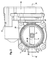
Figur 2- eine Seitenansicht des Drosselklappenstutzens nach Figur 1
Figur 3- einen Teilschnitt entlang der Linie A - A in
Figur 2 Figur 4- eine perspektivische Ansicht eines erfindungsgemäßen Ausführungsbeispiels eines Drosselklappenstutzens
Figur 5- eine Seitenansicht des Drosselklappenstutzens nach
Figur 4 Figur 6- einen Teilschnitt entlang der Linie B - B in
Figur 5 Figur 7- eine perspektivische Ansicht einer Drosselklappe.
- FIG. 1
- a perspective view of a throttle body, which is not part of the invention
- FIG. 2
- a side view of the throttle body according to Figure 1
- FIG. 3
- a partial section along the line A - A in Figure 2
- FIG. 4
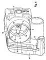
- a perspective view of an embodiment of a throttle body according to the invention
- FIG. 5
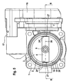
- a side view of the throttle body according to Figure 4
- FIG. 6
- a partial section along the line B - B in Figure 5
- FIG. 7
- a perspective view of a throttle.
Die in den Figuren dargestellten Drosselklappenstutzen besitzen ein Gehäuse 1 mit einer Durchströmöffnung 2 mit etwa kreisförmigen Querschnitt, in der eine Drosselklappe 3 mit etwa kreisförmiger Form zum Absperren der Durchströmöffnung 2 angeordnet ist. Die Drosselklappe 3 weist eine mittig über ihre Fläche sich erstreckende Aufnahmehülse 4 auf, in deren Axialausnehmung 5 runden Querschnitts eine Drosselklappenwelle 6 derart eingeführt ist, dass beidseitig die Enden der Drosselklappenwelle 6 an der Drosselklappe 3 hervorstehen und in Nadellager 7 im Gehäuse ragen.The throttle body shown in the figures have a housing 1 with a
Zur Befestigung der Drosselklappenwelle 6 in der Axialausnehmung 5 ist in der Aufnahmehülse 4 eine quer durchgehende Stufenbohrung 8 ausgebildet, deren große Stufe sich an einer Seite der Wandung der Aufnahmehülse 4 befindet und zur Aufnahme eines Schraubenkopfes 9 eine Befestigungsschraube 10 dient. Mit ihrem Gewindeschaft 11 ist die Befestigungsschraube 10 in eine entsprechende, zur Stufenbohrung 8 koaxiale Gewindebohrung 12 in der Drosselklappenwelle 6 eingeschraubt und verbindet so Drosselklappenwelle 6 und Drosselklappe 3 fest miteinander.To attach the
Die Nadellager sind mit ihren Außenringen 13 in entsprechenden Lagerausnehmungen 14 mit Presspassung eingesetzt.The needle bearings are used with their
Das rechte Ende der Drosselklappenwelle 6 ist durch einen elektromotorischen Antrieb entgegen der Kraft einer Rückstellfeder 15 aus einer Schließstellung der Drosselklappe 3 in deren Öffnungsstellung schwenkbar antreibbar. Der nicht dargestellte elektromotorische Antrieb befindet sich in einem Antriebsgehäuse 16 des Gehäuses 1, der auch einen Steckanschluss 17 für die Stromversorgung und die Ansteuerleitungen besitzt.The right end of the
Die Durchströmöffnung 2 des Drosselklappenstutzens besitzt im Bereich der Drosselklappe 3 einen etwa zylindrischen Abschnitt 18, an den sich beidseitig kurze stark konisch sich erweiternde Abschnitte anschließen, die wiederum durch leicht konisch sich erweiternde weitere Abschnitte 20 bis zu den Anschlussöffnungen 21 der Durchströmöffnung 2 fortgesetzt werden.The flow-through
Bei dem Ausführungsbeispiel der Figuren 1 bis 3 sind die Lagerausnehmungen 14 Stufenbohrungen, in deren großen Stufen 22 die Nadellager 7 eingesetzt sind und deren kleine Stufen 23 in die Durchströmöffnung 2 münden. Dabei entspricht der Durchmesser der kleinen Stufen 23 etwa dem Durchmesser der Drosselklappenwelle 6.In the exemplary embodiment of FIGS. 1 to 3, the bearing recesses 14 are stepped bores in whose
Der etwa zylindrische Abschnitt 18 besitzt einen stadionförmigen Querschnitt mit zueinander parallelen und zur Längsachse 26 der Drosselklappenwelle 6 rechtwinkligen Abstützbereichen 24 in den die Mündungsöffnungen der kleinen Stufen 23 umgebenden Bereichen an der Innenwand der Durchströmöffnung 2. Jeweils zwei einander zugewandte Enden der Abstützbereiche 24 sind durch kreisbogenförmige Bereiche 25 miteinander verbunden.The approximately
An den zueinander parallelen Abstützbereichen 24 des Abschnitts 18 der Durchströmöffnung 2 sind die stirnseitigen Öffnungen der Aufnahmehülse 4 in Anlage, die Anlauflaufflächen 27 bilden und die Position der Drosselklappe 3 in der Durchströmöffnung 2 axial zur Längsachse 26 der Drosselklappenwelle 6 bestimmen und sichern.At the mutually
Da bei dem Ausführungsbeispiel der Figuren 1 bis 3 sowohl die Drosselklappe 3 als auch das Gehäuse 1 aus Kunststoff spritzgegossen sind und somit einen zumindest annähernd gleichen Wärmeausdehnungskoeffizienten besitzen, kann es bei Wärmebelastung nicht zu einem Verklemmen der Anlaufflächen 27 der Aufnahmehülse 4 zwischen den Abstützbereichen 24 des Gehäuses 1 kommen.Since in the embodiment of Figures 1 to 3, both the
Die Herstellung aus Kunststoff führt zu einem geringen Gewicht und niedrigen Herstellkosten.The production of plastic leads to a low weight and low production costs.
Bei dem erfindugsgemäßen Ausführungsbeispiel der Figuren 4 bis 6 sind die Lagerausnehmungen 14 durchgehende Bohrungen gleichen Durchmessers, in die die Nadellager 7 mit ihrem Außenring 13 mit Preßpassung eingesetzt sind.In the erfindugsgemäßen embodiment of Figures 4 to 6, the bearing recesses 14 through holes of the same diameter, in which the
Die Drosselklappe 3 besitzt den gleichen Aufbau wie bei dem Ausführungsbeispiel der Figuren 1 bis 3 und weist auch an den stirnseitigen Enden ihrer Aufnahmehülse 4 die zueinander parallelen und zur Längsachse 26 der Drosselklappenwelle 6 rechtwinkligen Anlaufflächen 27 auf. Diesen Anlaufflächen 27 sind an den zur Durchströmöffnung 2 gerichteten Stirnseiten der Außenringe 13 der Nadellager 7 in Anlage, die um ein geringes Maß in den Abschnitt 18 kreisförmigen Querschnitts der Durchströmöffnung 2 ragen. Diese zur Durchströmöffnung 2 gerichteten Stirnseiten bilden dabei Abstützbereiche 24', die die Lage der Drosselklappe 3 axial zur Längsachse 26 der Drosselklappenwelle 6 in dem Abschnitt 18 der Durchströmöffnung 2 bestimmen und sichern.The
Die Bestimmung dieser Lager erfolgt durch das entsprechende axiale Einschieben mit Presspassung der Nadellager 7 in die Lagerausnehmungen 14.The determination of these bearings is carried out by the corresponding axial insertion with interference fit of the
Bei dem Ausführungsbeispiel der Figuren 4 bis 6 sind sowohl Gehäuse 1 als auch Drosselklappe 3 Spritzgussteile aus Aluminium.In the embodiment of Figures 4 to 6 are both housing 1 and
Die Drosselklappe 3 in Figur 7 ist die Darstellung der Drosselklappe 3, die für beide Ausführungsbeispiele den gleichen Aufbau besitzt und sich nur in ihrem Werkstoff unterscheidet.The
Claims (13)
- Throttle valve body for an internal combustion engine, comprising a housing (1) and a crossflow opening (2) in the housing, which can be blocked by a throttle valve (3), the throttle valve being arranged on a throttle valve shaft (6) which can be driven so as to pivot about its longitudinal axis (26) extending transversely with respect to the longitudinal axis of the crossflow opening and whose free ends are mounted such that they can pivot in bearings (7) which are arranged in bearing recesses (14) in the housing, and the throttle valve shaft being secured against axial displacement by an axial safety device, in which case, in its regions in which the throttle valve shaft protrudes axially, the throttle valve has run-on surfaces which bear on supporting regions fixed to the housing, characterized in that the supporting regions (24') are those ends of the bearings which are oriented towards the crossflow opening (2).
- Throttle valve body according to one of the preceding claims, characterized in that the run-on surfaces (27) extend at right angles to the longitudinal axis of the throttle valve shaft (6) and parallel to each other.
- Throttle valve body according to one of the preceding claims, characterized in that the supporting regions (24') extend at right angles to the longitudinal axis (26) of the throttle valve shaft (6).
- Throttle valve body according to one of the preceding claims, characterized in that the throttle valve (3) has a holding sleeve (4), in whose axial recess (5) the throttle valve shaft (6) is firmly arranged and whose ends form the run-on surfaces (27).
- Throttle valve body according to one of the preceding claims, characterized in that the throttle valve (3) has a stadium-like circumferential contour which, starting from the mutually parallel run-on surfaces (27), is formed in a circular and/or curved shape.
- Throttle valve body according to one of the preceding claims, characterized in that the extent of the supporting regions (24') in the direction of the longitudinal axis of the crossflow opening (2) and/or transversely with respect to the direction of the longitudinal axis of the crossflow opening (2) corresponds approximately to the external diameter of the holding sleeve (4).
- Throttle valve body according to Claim 4, characterized in that the throttle valve shaft (6) is fixed in the axial recess (5) of the holding sleeve (4) by means of a pin passing transversely through holding sleeve (4) and throttle valve shaft (6) or a screw (10) passing through transversely.
- Throttle valve body according to one of the preceding claims, characterized in that the bearings have bearing sleeves which are inserted into the bearing recesses (14) of the housing (1) with a press fit.
- Throttle valve body according to Claim 8, characterized in that the bearing sleeves project into the crossflow opening (2) by a small amount.
- Throttle valve body according to either of Claims 8 and 9, characterized in that the bearings are rolling-contact bearings with an inner ring and an outer ring (13), those ends of the inner rings or of the outer rings (13) which are oriented toward the crossflow opening (2) forming the supporting regions (24').
- Throttle valve body according to one of the preceding claims, characterized in that the housing (1) and/or the throttle valve (3) consist of a plastic.
- Throttle valve body according to one of Claims 1 to 10, characterized in that the housing (1) and/or the throttle valve (3) consist of metal, in particular lightweight metal.
- Throttle valve body according to one of the preceding claims, characterized in that the housing (1) and/or the throttle valve (3) is an injection molding.
Applications Claiming Priority (3)
| Application Number | Priority Date | Filing Date | Title |
|---|---|---|---|
| DE10157963 | 2001-11-26 | ||
| DE10157963A DE10157963A1 (en) | 2001-11-26 | 2001-11-26 | throttle body |
| PCT/DE2002/003822 WO2003046419A1 (en) | 2001-11-26 | 2002-10-10 | Throttle valve body |
Publications (2)
| Publication Number | Publication Date |
|---|---|
| EP1448921A1 EP1448921A1 (en) | 2004-08-25 |
| EP1448921B1 true EP1448921B1 (en) | 2006-12-06 |
Family
ID=7707013
Family Applications (1)
| Application Number | Title | Priority Date | Filing Date |
|---|---|---|---|
| EP02774454A Expired - Lifetime EP1448921B1 (en) | 2001-11-26 | 2002-10-10 | Throttle valve body |
Country Status (6)
| Country | Link |
|---|---|
| US (1) | US6871631B2 (en) |
| EP (1) | EP1448921B1 (en) |
| BR (1) | BR0214397A (en) |
| CA (1) | CA2468055A1 (en) |
| DE (2) | DE10157963A1 (en) |
| WO (1) | WO2003046419A1 (en) |
Families Citing this family (7)
| Publication number | Priority date | Publication date | Assignee | Title |
|---|---|---|---|---|
| JP2006017080A (en) * | 2004-07-05 | 2006-01-19 | Denso Corp | Intake air control device for internal combustion engine |
| DE102005009160A1 (en) * | 2004-08-13 | 2006-02-23 | Robert Bosch Gmbh | Exhaust control element for supercharging systems of internal combustion engines |
| US8342148B2 (en) * | 2006-01-20 | 2013-01-01 | Ford Global Technologies | Throttle valve for internal combustion engine |
| JP4551351B2 (en) * | 2006-04-18 | 2010-09-29 | 株式会社デンソー | Throttle valve device |
| DE102012110763B4 (en) * | 2012-11-09 | 2015-02-05 | Pierburg Gmbh | Valve device for an internal combustion engine or an electric vehicle |
| WO2014150820A1 (en) * | 2013-03-15 | 2014-09-25 | Borgwarner Inc. | A compact rotary wastegate valve |
| DE102017006770A1 (en) | 2017-07-18 | 2019-01-24 | Johannes Klimeck jun. | THROTTLE VALVE ADJUSTABLE, METHOD FOR OPERATING A THROTTOP VALVES, INTERNAL COMBUSTION ENGINE, AND MOTOR VEHICLE |
Family Cites Families (7)
| Publication number | Priority date | Publication date | Assignee | Title |
|---|---|---|---|---|
| DE3802243A1 (en) * | 1988-01-27 | 1989-08-10 | Daimler Benz Ag | STORAGE OF A THROTTLE VALVE SHAFT IN THE HOUSING OF AN EXHAUST PIPE |
| FR2692622B1 (en) * | 1992-06-17 | 1994-09-16 | Solex | Rotary throttle member for internal combustion engine power supply installation and throttle body including application. |
| DE4229299C1 (en) * | 1992-09-02 | 1994-01-13 | Mtu Friedrichshafen Gmbh | Throttle valve arrangement for an exhaust pipe of an internal combustion engine |
| DE4334180A1 (en) * | 1993-10-07 | 1995-04-13 | Bosch Gmbh Robert | Throttling device |
| FR2746198B1 (en) * | 1996-03-18 | 1998-05-22 | IMPROVEMENTS IN GAS FLOW METERING DEVICES | |
| DE19909982A1 (en) * | 1999-03-06 | 2000-09-07 | Bosch Gmbh Robert | Throttle body for controlling the performance of an internal combustion engine |
| DE10105526B4 (en) * | 2001-02-07 | 2004-12-23 | Robert Bosch Gmbh | Method of making a valve assembly |
-
2001
- 2001-11-26 DE DE10157963A patent/DE10157963A1/en not_active Withdrawn
-
2002
- 2002-10-10 CA CA002468055A patent/CA2468055A1/en not_active Abandoned
- 2002-10-10 BR BR0214397-6A patent/BR0214397A/en active Search and Examination
- 2002-10-10 DE DE50208915T patent/DE50208915D1/en not_active Expired - Lifetime
- 2002-10-10 EP EP02774454A patent/EP1448921B1/en not_active Expired - Lifetime
- 2002-10-10 WO PCT/DE2002/003822 patent/WO2003046419A1/en active IP Right Grant
-
2004
- 2004-05-17 US US10/846,581 patent/US6871631B2/en not_active Expired - Fee Related
Also Published As
| Publication number | Publication date |
|---|---|
| US20040211391A1 (en) | 2004-10-28 |
| EP1448921A1 (en) | 2004-08-25 |
| DE50208915D1 (en) | 2007-01-18 |
| US6871631B2 (en) | 2005-03-29 |
| BR0214397A (en) | 2004-11-03 |
| DE10157963A1 (en) | 2003-06-05 |
| CA2468055A1 (en) | 2003-06-05 |
| WO2003046419A1 (en) | 2003-06-05 |
Similar Documents
| Publication | Publication Date | Title |
|---|---|---|
| DE69921875T2 (en) | Two-piece throttle body | |
| EP1828623B1 (en) | Device for fastening an add-on and a support at a distance from each other | |
| EP1974597B1 (en) | Shaft system for a portable, handheld work tool and portable, handheld work tool | |
| EP1585912B1 (en) | Modular unit comprising a bush for chain drives | |
| DE20220527U1 (en) | Belt tensioner with installation pin | |
| DE10254937B4 (en) | Moment transmission device with torque limiter | |
| DE3327453A1 (en) | FUEL GEAR PUMP | |
| EP3885609B1 (en) | Belt tensioning device | |
| DE102014201742A1 (en) | ACTUATOR FOR A MOTOR VEHICLE, ESPECIALLY FOR A MOTOR VEHICLE SEAT | |
| EP3696384B1 (en) | Exhaust flap | |
| DE202005016992U1 (en) | Belt tightener for a belt drive in an internal combustion engine comprises a glide element arrangement incorporating at least two opposing gliding surfaces are made of the same material | |
| EP3290757B1 (en) | Rotary valve with compact sealing unit | |
| WO2012104242A1 (en) | Device for varying the relative angle position of a camshaft with respect to a crankshaft of an internal combustion engine | |
| DE102011083263A1 (en) | Electric machine, in particular starting device, and method for producing a support bearing arrangement of an electrical machine | |
| EP1448921B1 (en) | Throttle valve body | |
| EP3227540B1 (en) | Flap device for an internal combustion engine | |
| DE4301241C2 (en) | Longitudinal adjustment gear, in particular seat adjustment gear in a motor vehicle | |
| DE102005024205B4 (en) | An air intake control device having a tensile absorption structure | |
| WO2003095839A1 (en) | Radial piston pump for a fuel injection system having improved high-pressure resistance | |
| EP1076174B1 (en) | Single cylinder high pressure pump | |
| EP1356197B1 (en) | Device for repositioning a rotating element | |
| DE102020118449A1 (en) | Linear Actuator, Housing, Actuation System, and Assembly Method | |
| EP1419331B1 (en) | Throttle valve arrangement | |
| DE102005025872A1 (en) | Fuel metering unit for a high-pressure fuel pump and high-pressure fuel pump | |
| EP3014145A1 (en) | Adjustable camshaft |
Legal Events
| Date | Code | Title | Description |
|---|---|---|---|
| PUAI | Public reference made under article 153(3) epc to a published international application that has entered the european phase |
Free format text: ORIGINAL CODE: 0009012 |
|
| 17P | Request for examination filed |
Effective date: 20040323 |
|
| AK | Designated contracting states |
Kind code of ref document: A1 Designated state(s): AT BE CH CY DE DK ES FI FR GB GR IE IT LI LU MC NL PT SE TR |
|
| GRAP | Despatch of communication of intention to grant a patent |
Free format text: ORIGINAL CODE: EPIDOSNIGR1 |
|
| GRAS | Grant fee paid |
Free format text: ORIGINAL CODE: EPIDOSNIGR3 |
|
| GRAA | (expected) grant |
Free format text: ORIGINAL CODE: 0009210 |
|
| AK | Designated contracting states |
Kind code of ref document: B1 Designated state(s): DE FR IT |
|
| REF | Corresponds to: |
Ref document number: 50208915 Country of ref document: DE Date of ref document: 20070118 Kind code of ref document: P |
|
| ET | Fr: translation filed | ||
| PLBE | No opposition filed within time limit |
Free format text: ORIGINAL CODE: 0009261 |
|
| STAA | Information on the status of an ep patent application or granted ep patent |
Free format text: STATUS: NO OPPOSITION FILED WITHIN TIME LIMIT |
|
| 26N | No opposition filed |
Effective date: 20070907 |
|
| PGFP | Annual fee paid to national office [announced via postgrant information from national office to epo] |
Ref country code: IT Payment date: 20091023 Year of fee payment: 8 |
|
| REG | Reference to a national code |
Ref country code: FR Ref legal event code: TP |
|
| PG25 | Lapsed in a contracting state [announced via postgrant information from national office to epo] |
Ref country code: IT Free format text: LAPSE BECAUSE OF NON-PAYMENT OF DUE FEES Effective date: 20101010 |
|
| PGFP | Annual fee paid to national office [announced via postgrant information from national office to epo] |
Ref country code: DE Payment date: 20121031 Year of fee payment: 11 Ref country code: FR Payment date: 20121031 Year of fee payment: 11 |
|
| REG | Reference to a national code |
Ref country code: DE Ref legal event code: R119 Ref document number: 50208915 Country of ref document: DE Effective date: 20140501 |
|
| REG | Reference to a national code |
Ref country code: FR Ref legal event code: ST Effective date: 20140630 |
|
| PG25 | Lapsed in a contracting state [announced via postgrant information from national office to epo] |
Ref country code: FR Free format text: LAPSE BECAUSE OF NON-PAYMENT OF DUE FEES Effective date: 20131031 Ref country code: DE Free format text: LAPSE BECAUSE OF NON-PAYMENT OF DUE FEES Effective date: 20140501 |