EP1448856B1 - Retractable road barrier - Google Patents
Retractable road barrier Download PDFInfo
- Publication number
- EP1448856B1 EP1448856B1 EP02803887A EP02803887A EP1448856B1 EP 1448856 B1 EP1448856 B1 EP 1448856B1 EP 02803887 A EP02803887 A EP 02803887A EP 02803887 A EP02803887 A EP 02803887A EP 1448856 B1 EP1448856 B1 EP 1448856B1
- Authority
- EP
- European Patent Office
- Prior art keywords
- barrier
- elements
- barrier element
- supporting
- road surface
- Prior art date
- Legal status (The legal status is an assumption and is not a legal conclusion. Google has not performed a legal analysis and makes no representation as to the accuracy of the status listed.)
- Expired - Lifetime
Links
Images



Classifications
-
- E—FIXED CONSTRUCTIONS
- E01—CONSTRUCTION OF ROADS, RAILWAYS, OR BRIDGES
- E01F—ADDITIONAL WORK, SUCH AS EQUIPPING ROADS OR THE CONSTRUCTION OF PLATFORMS, HELICOPTER LANDING STAGES, SIGNS, SNOW FENCES, OR THE LIKE
- E01F15/00—Safety arrangements for slowing, redirecting or stopping errant vehicles, e.g. guard posts or bollards; Arrangements for reducing damage to roadside structures due to vehicular impact
- E01F15/02—Continuous barriers extending along roads or between traffic lanes
- E01F15/12—Continuous barriers extending along roads or between traffic lanes and having means for providing occasional passage, e.g. for emergency vehicles
Definitions
- the present invention relates to safety barriers for road use of the type comprising at least one barrier element and a supporting structure for supporting the barrier element, provided with means for anchoring thereof to the ground, wherein said supporting structure is movable between a first position, in which the barrier element is in an operative position above the road surface, and a second position, in which the barrier element is in an inoperative position in which it does not substantially project above the road surface, wherein in said inoperative condition the barrier element is received inside a trench formed in the road surface, wherein the supporting structure includes at least one supporting column articulated at one of its ends to a bracket for anchorage to the ground and, at the opposite end, to the barrier element, said supporting column being pivotable between an operative upright position and an inoperative lowered position, and in which means are provided for controlling rotation of said supporting column.
- a road barrier of the above indicated type is disclosed in document DE-A-34 20 503 .
- more barrier elements are provided which, when in the lowered position, are spaced apart from each other, so that free spaces are defined therebetween which require the provision of additional platforms in order to cover the trench which receives the barrier elements in the lowered condition.
- interruptions are formed at the areas interposed between each lowered element and an adjacent raised element.
- this solution shows a barrier with a connecting element which connects a retractable barrier element to a non-retractable barrier element, it does not provide for a connecting element between two barrier elements which are both retractable, so that there are not ample possibilities to choose the barrier portion which one wishes to retract.
- the barrier of this second known solution does not ensure a continuous surface both above and on the two sides of the barrier and moreover it has columns for supporting the retractable element which are directly articulated to the walls of the trench in which the retracted element is received, so that any operations for replacing a damaged barrier element are lengthy and costly.
- the object of the present invention is that of providing a road barrier which is able to overcome all the above mentioned drawbacks.
- the invention provides a road barrier having all the features which have been indicated at the beginning of the present description and further characterized in that said safety barrier comprises a succession of sets of one or more barrier elements, the barrier elements of each set being rigidly connected to each other, and adjacent sets of barrier elements being connected to each other by means of articulated connecting elements having variable length, which enable a relative displacement in a vertical direction of any set with respect to the other, while always defining a continuous upper surface and two side continuous side surfaces of the barrier in any position of any set of barrier elements of the barrier.
- each set of barrier elements is constituted by barrier elements whose supporting columns are articulated to a bracket which is anchored to the ground, each of these sets forms a unit which can be easily removed and replaced.
- a further object of the present invention is that of ensuring that the barrier elements can be all moved to their lowered position even in case of an absence of the electric main supply, which condition may well take place in case of an accident, or in case of a fire inside the tunnel.
- the barrier according to the invention is further characterized in that a solenoid valve is provided which can be activated in order to put a cylinder for raising the barrier element in a discharge condition, in order to cause lowering of the respective barrier element, and in that emergency electric supply means are provided for activating said solenoid valve in case of a failure in the main supply of electric current.
- a solenoid valve is provided which can be activated in order to put a cylinder for raising the barrier element in a discharge condition, in order to cause lowering of the respective barrier element
- emergency electric supply means are provided for activating said solenoid valve in case of a failure in the main supply of electric current.
- the reference number 1 designates as a whole a road tunnel having two lanes 2, 3 for passage of traffic in two opposite directions, which are separated by a safety barrier 4 built according to the invention.
- the barrier 4 comprises an aligned succession of barrier elements 5 consisting of metal channel section with reversed-U cross section and undulations for stiffening, if so required, the said barrier elements being each carried by a set of three supporting columns 6.
- Each column 6 has one end articulated in 7 ( Figure 2) to the respective barrier element 5, and the opposite end articulated in 8 to an attachment element anchored to the ground.
- the barrier elements 5 are rigidly connected together in sets of a number of elements (for example, three) by connecting elements 9 consisting of reversed-U channel section, which are set on top of one other and are bolted by means of screws 9a (see Figure 7) to the barrier elements 5.
- the ensemble consisting of three barrier elements 5 making up each set can be displaced between its normal operating position, in which it projects above the road surface ( Figure 2), and a lowered, inoperative, position, which is reached by means of simultaneous rotation downwards of the columns 6 about their respective bottom articulations 8 and in which the barrier elements 5 disappear inside a trench 10 made in the read surface.
- the movement of the barrier elements 5 between an inoperative position and the operative position is controlled, for each set of three barrier elements 5 connected rigidly together by the connecting elements 9, by a single hydraulic cylinder 11 having one end articulated to the ground and the opposite end articulated to a bracket 12 ( Figure 3) of the central column 6 of the set of three columns 6 associated to the central barrier element 5 of the set of three barrier elements 5 rigidly connected together.
- the said central column 6 is provided with a bracing arm 13.
- a plate 40 is set between each pair of adjacent columns 6 (only one plate 40 being illustrated), which has both a stiffening function and the function of partially closing the trench 10 when the barrier is raised.
- the hydraulic cylinder 11 is supplied by a pump 14 which is controlled by an electric motor 15, the assembly consisting of the motor 15 and the pump 14 being mounted inside a channel 16 ( Figure 3) anchored to the ground. Fixed to the said channel are also the attachments 17 which are provided in the trench 10 (see also Figure 7). In this way, the entire module consisting of the channel 16 and all the components illustrated in Figure 3 can be readily and quickly replaced.
- the system is provided with means for automatic control of lowering of the barrier in the event of failure of electric power supply (as in the case of an accident in a tunnel).
- a 12-V emergency electric power generator may be envisaged which drives a solenoid valve that controls the cylinder.
- Figure 4 is a perspective view which clearly illustrates the connecting element 9 that rigidly joins barrier elements 5 to form a set of three elements.
- Figure 5 is a perspective view illustrating a connecting structure 18 which is set between two adjacent sets of three barrier elements 5.
- the structure 18 comprises two portions of channel section 18a, 18b which are articulated in 7a, 7b to two adjacent columns 6 (see Figure 6) and which are moreover connected together in an articulated way by means of transverse pins 7c.
- the articulation in 7b is obtained by engagement of the side pins in side slits 20 made in the sides of the respective barrier element 5.
- the articulation 7c is also obtained by means of side pins which engage both the slits 20 made in the element 18a and the slits 21 made in the element 18b.
- the fluid cylinder is of the single effect type, which causes raising of the respective barrier element when it is supplied with fluid under pressure, whereas it automatically returns to the condition corresponding to the lowering of the barrier element when its hydraulic chamber is connected to discharge.
- this chamber of the fluid cylinder can be connected to a discharge by means of a solenoid valve which can be activated by an emergency electric supply (such as a backup battery, or an emergency electric generator) in case the main supply is interrupted following an emergency situation such as in case of a fire within the tunnel.
- an emergency electric supply such as a backup battery, or an emergency electric generator
- the elements of the barrier can also be used to carry an optical guide.
- a duct made of transparent plastic material such as polycarbon
- a light source at one end for example constituted by a plurality of LED devices
- a closing cover at the opposite end with a reflective film for example constituted by a plurality of LED devices
- the LED light source is supplied with a low voltage direct current and offers a high degree of safety in the system as well as a low energy consumption.
- this optical guide enables the forwarding of coloured light signals, if necessary intermittent, which are controlled by an electronic control unit and have the purpose for instance of signalling the proper safety spacing between each vehicle and the subsequent one, the safety speed and the stop areas for the vehicles which travel through the tunnel.
- the idea underlying the invention is to provide a safety barrier that can be quickly brought into an inoperative condition in which it does not project above the road surface, with the consequent advantages that have been mentioned at the beginning of the present description.
- the structure and arrangement of the barrier elements that have been illustrated herein, by way of example could be altogether different.
- a further preferred characteristic of the invention lies in the characteristic described previously, which regards the possibility of displacing only one portion of the barrier between the operative position and the inoperative position, without changing the positions of the adjacent portions.
- each lowerable barrier unit comprises a single barrier element.
Landscapes
- Engineering & Computer Science (AREA)
- Architecture (AREA)
- Civil Engineering (AREA)
- Structural Engineering (AREA)
- Refuge Islands, Traffic Blockers, Or Guard Fence (AREA)
- Road Signs Or Road Markings (AREA)
- Lock And Its Accessories (AREA)
- Switches With Compound Operations (AREA)
- Vehicle Body Suspensions (AREA)
- Vehicle Step Arrangements And Article Storage (AREA)
- Closing And Opening Devices For Wings, And Checks For Wings (AREA)
Abstract
Description
- The present invention relates to safety barriers for road use of the type comprising at least one barrier element and a supporting structure for supporting the barrier element, provided with means for anchoring thereof to the ground, wherein said supporting structure is movable between a first position, in which the barrier element is in an operative position above the road surface, and a second position, in which the barrier element is in an inoperative position in which it does not substantially project above the road surface, wherein in said inoperative condition the barrier element is received inside a trench formed in the road surface, wherein the supporting structure includes at least one supporting column articulated at one of its ends to a bracket for anchorage to the ground and, at the opposite end, to the barrier element, said supporting column being pivotable between an operative upright position and an inoperative lowered position, and in which means are provided for controlling rotation of said supporting column.
- A road barrier of the above indicated type is disclosed in document
DE-A-34 20 503 . In this known solution, more barrier elements are provided which, when in the lowered position, are spaced apart from each other, so that free spaces are defined therebetween which require the provision of additional platforms in order to cover the trench which receives the barrier elements in the lowered condition. Moreover, in this known solution, in case only some of the barrier elements are lowered into the inoperative position, interruptions are formed at the areas interposed between each lowered element and an adjacent raised element. Finally, the solution shown in the above indicated document has a structure such that any operations for replacing a damaged barrier portion, for example due to a road accident, become lengthy and troublesome. - The same drawbacks are encountered also in the barrier shown in document
FR-A-2 750 148 - The object of the present invention is that of providing a road barrier which is able to overcome all the above mentioned drawbacks.
- In view of achieving this object, the invention provides a road barrier having all the features which have been indicated at the beginning of the present description and further characterized in that said safety barrier comprises a succession of sets of one or more barrier elements, the barrier elements of each set being rigidly connected to each other, and adjacent sets of barrier elements being connected to each other by means of articulated connecting elements having variable length, which enable a relative displacement in a vertical direction of any set with respect to the other, while always defining a continuous upper surface and two side continuous side surfaces of the barrier in any position of any set of barrier elements of the barrier.
- Due to the above indicated features, there exists an ample flexibility in the configurations which can be selected for the barrier, since any one of the sets of barrier elements can be displaced from the operative raised position to the lowered inoperative position, while the sets adjacent to the ends of the lowered set can be either kept raised or lowered, at will, the connecting elements between adjacent sets ensuring the continuity of the upper surface and the two side surfaces of the barrier in any case. Furthermore, since each set of barrier elements is constituted by barrier elements whose supporting columns are articulated to a bracket which is anchored to the ground, each of these sets forms a unit which can be easily removed and replaced.
- A further object of the present invention is that of ensuring that the barrier elements can be all moved to their lowered position even in case of an absence of the electric main supply, which condition may well take place in case of an accident, or in case of a fire inside the tunnel.
- In view of efficiently solving this problem, the barrier according to the invention is further characterized in that a solenoid valve is provided which can be activated in order to put a cylinder for raising the barrier element in a discharge condition, in order to cause lowering of the respective barrier element, and in that emergency electric supply means are provided for activating said solenoid valve in case of a failure in the main supply of electric current. In this manner, in any situation of emergency in which the electric main supply has been interrupted, it is possible to cause an automatic lowering of the barrier elements to their retracted position.
- Further characteristics and advantages of the present invention will emerge from the ensuing description, with reference to the attached drawings, which are provided purely by way of non-limiting example and in which:
- Figure 1 is a schematic view illustrating a road tunnel in which the two traffic lanes (in opposite directions) for motor vehicles are divided by a safety barrier according to the invention;
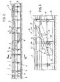
- Figure 2 is a side elevation of one portion of the safety barrier of Figure 1 in its operative condition;
- Figure 3 is a perspective view of an element of the barrier of Figures 1 and 2 in its operative condition;
- Figure 4 illustrates a connecting element which rigidly connects two barrier elements adjacent to one another;
- Figure 5 is a perspective view of an articulated connecting element which connects together two sets of barrier elements in such a way as to enable movement of one set with respect to the other;
- Figure 6 is a schematic side view which shows a connecting element between two different sets of barrier elements in two different operating conditions; and
- Figure 7 is a sectional view taken along the line VII-VII of Figure 6.
- In Figure 1, the
reference number 1 designates as a whole a road tunnel having twolanes safety barrier 4 built according to the invention. - The
barrier 4 comprises an aligned succession ofbarrier elements 5 consisting of metal channel section with reversed-U cross section and undulations for stiffening, if so required, the said barrier elements being each carried by a set of three supportingcolumns 6. Eachcolumn 6 has one end articulated in 7 (Figure 2) to therespective barrier element 5, and the opposite end articulated in 8 to an attachment element anchored to the ground. - The
barrier elements 5 are rigidly connected together in sets of a number of elements (for example, three) by connectingelements 9 consisting of reversed-U channel section, which are set on top of one other and are bolted by means ofscrews 9a (see Figure 7) to thebarrier elements 5. The ensemble consisting of threebarrier elements 5 making up each set can be displaced between its normal operating position, in which it projects above the road surface (Figure 2), and a lowered, inoperative, position, which is reached by means of simultaneous rotation downwards of thecolumns 6 about theirrespective bottom articulations 8 and in which thebarrier elements 5 disappear inside atrench 10 made in the read surface. The movement of thebarrier elements 5 between an inoperative position and the operative position is controlled, for each set of threebarrier elements 5 connected rigidly together by the connectingelements 9, by a singlehydraulic cylinder 11 having one end articulated to the ground and the opposite end articulated to a bracket 12 (Figure 3) of thecentral column 6 of the set of threecolumns 6 associated to thecentral barrier element 5 of the set of threebarrier elements 5 rigidly connected together. For stiffening purposes, the saidcentral column 6 is provided with a bracing arm 13. Aplate 40 is set between each pair of adjacent columns 6 (only oneplate 40 being illustrated), which has both a stiffening function and the function of partially closing thetrench 10 when the barrier is raised. Thehydraulic cylinder 11 is supplied by apump 14 which is controlled by anelectric motor 15, the assembly consisting of themotor 15 and thepump 14 being mounted inside a channel 16 (Figure 3) anchored to the ground. Fixed to the said channel are also theattachments 17 which are provided in the trench 10 (see also Figure 7). In this way, the entire module consisting of thechannel 16 and all the components illustrated in Figure 3 can be readily and quickly replaced. - The system is provided with means for automatic control of lowering of the barrier in the event of failure of electric power supply (as in the case of an accident in a tunnel). For example, a 12-V emergency electric power generator may be envisaged which drives a solenoid valve that controls the cylinder.
- Figure 4 is a perspective view which clearly illustrates the connecting
element 9 that rigidly joinsbarrier elements 5 to form a set of three elements. Figure 5 is a perspective view illustrating a connectingstructure 18 which is set between two adjacent sets of threebarrier elements 5. Thestructure 18 comprises two portions ofchannel section transverse pins 7c. The articulation in 7b is obtained by engagement of the side pins inside slits 20 made in the sides of therespective barrier element 5. Thearticulation 7c is also obtained by means of side pins which engage both theslits 20 made in theelement 18a and theslits 21 made in theelement 18b. - Thanks to the arrangement described above, when the set of three
barrier elements 5 that is on the left, with reference to Figure 6, is lowered, with respect to the set of three elements that is on the right-hand side, the connectingstructure 18 moves from the condition illustrated with a solid line to the condition illustrated with a dashed line. In this way, continuity of the barrier is ensured, and at the same time the possibility is guaranteed for just a few portions of the barrier to be lowered into the inoperative position, leaving the remaining portions in the normal operating condition. - According to a further important feature of the invention, the fluid cylinder is of the single effect type, which causes raising of the respective barrier element when it is supplied with fluid under pressure, whereas it automatically returns to the condition corresponding to the lowering of the barrier element when its hydraulic chamber is connected to discharge. According to the invention, this chamber of the fluid cylinder can be connected to a discharge by means of a solenoid valve which can be activated by an emergency electric supply (such as a backup battery, or an emergency electric generator) in case the main supply is interrupted following an emergency situation such as in case of a fire within the tunnel. The barrier according to the invention is thus able to provide a high degree of safety since it is automatically brought to the retracted condition in the above described emergency situations.
- Finally, the elements of the barrier can also be used to carry an optical guide. For instance, inside some or all the barrier elements it is possible to provide a duct made of transparent plastic material (such as polycarbon) with a OLF film provided inside the duct, a light source at one end, for example constituted by a plurality of LED devices, and a closing cover at the opposite end with a reflective film. The LED light source is supplied with a low voltage direct current and offers a high degree of safety in the system as well as a low energy consumption. The use of this optical guide enables the forwarding of coloured light signals, if necessary intermittent, which are controlled by an electronic control unit and have the purpose for instance of signalling the proper safety spacing between each vehicle and the subsequent one, the safety speed and the stop areas for the vehicles which travel through the tunnel.
- From the foregoing description it is evident that the idea underlying the invention is to provide a safety barrier that can be quickly brought into an inoperative condition in which it does not project above the road surface, with the consequent advantages that have been mentioned at the beginning of the present description. Of course, the structure and arrangement of the barrier elements that have been illustrated herein, by way of example could be altogether different. The same applies to the devices used for controlling movement of the barrier elements. A further preferred characteristic of the invention lies in the characteristic described previously, which regards the possibility of displacing only one portion of the barrier between the operative position and the inoperative position, without changing the positions of the adjacent portions.
- For example, It would also be possible that each lowerable barrier unit comprises a single barrier element.
Claims (5)
- A safety barrier (4) for road use, comprising:- at least one barrier element (5), and- a supporting structure (6) for supporting the barrier element, provided with means for anchoring thereof to the ground (8),- wherein said supporting structure is displaceable between a first position, in which the barrier element (5) is in an operative condition above (9) the road surface (3), and a second position, in which the barrier element is in an inoperative condition in which it does not substantially project above the road surface,- wherein, in said inoperative condition, the barrier element (5) is received inside a trench (10) formed in the road surface,- wherein the supporting structure includes at least one supporting column (6) articulated at one of its ends to a bracket (17) for anchorage to the ground and, at the opposite end, to the barrier element (5); said supporting column (6) being pivotable between un upright operative position and a lowered inoperative position,- wherein means are provided (11) for controlling rotation of said supporting column (6),characterized in that said safety barrier comprises a succession of sets of one or more barrier elements (5), the elements of each set being rigidly connected to each other (9) and adjacent sets being connected to each other by means of articulated connecting elements having a variable length (18), which enable a relative displacement in the vertical direction of one set relative to the other, while always defining a continuous upper surface and two continuous side surfaces for the barrier in any position of any set of the barrier.
- Barrier according to claim 1, characterized in that said barrier element (5) and said articulated connecting elements (18) are in form of metal profiles having a cross-section in form of an inverted U, each having an upper wall and two side walls extending through a substantial portion of the height of said supporting columns.
- Barrier according to claim 1, characterized in that said means for controlling rotation of said supporting column include a fluid cylinder, a solenoid valve for connecting said fluid cylinder a to discharge, in order to cause lowering of the respective barrier element in its retracted position, and emergency electric supply means for activating said solenoid valve in case of an interruption of the electric main supply.
- Barrier according to claim 3, characterized in that said means for activating the solenoid valve are able to become automatically operative in case of an interruption of electric main supply.
- Barrier according to any of the previous claims, characterized in that an optical guide is associated to one or more elements of the barrier.
Applications Claiming Priority (3)
| Application Number | Priority Date | Filing Date | Title |
|---|---|---|---|
| ITTO20011105 | 2001-11-27 | ||
| IT2001TO001105A ITTO20011105A1 (en) | 2001-11-27 | 2001-11-27 | ,, RETRACTABLE ROAD BARRIER ,,. |
| PCT/IB2002/004834 WO2003046289A1 (en) | 2001-11-27 | 2002-11-19 | Retractable road barrier |
Publications (2)
| Publication Number | Publication Date |
|---|---|
| EP1448856A1 EP1448856A1 (en) | 2004-08-25 |
| EP1448856B1 true EP1448856B1 (en) | 2007-08-22 |
Family
ID=11459312
Family Applications (1)
| Application Number | Title | Priority Date | Filing Date |
|---|---|---|---|
| EP02803887A Expired - Lifetime EP1448856B1 (en) | 2001-11-27 | 2002-11-19 | Retractable road barrier |
Country Status (7)
| Country | Link |
|---|---|
| US (1) | US6926462B1 (en) |
| EP (1) | EP1448856B1 (en) |
| AT (1) | ATE371058T1 (en) |
| AU (1) | AU2002365492A1 (en) |
| DE (1) | DE60222009T2 (en) |
| IT (1) | ITTO20011105A1 (en) |
| WO (1) | WO2003046289A1 (en) |
Cited By (2)
| Publication number | Priority date | Publication date | Assignee | Title |
|---|---|---|---|---|
| US20230121725A1 (en) * | 2021-10-14 | 2023-04-20 | Vandorf PAT1 Inc. | Pedestrian Access Terminal |
| US12084819B2 (en) | 2021-07-15 | 2024-09-10 | Three Smith Group Limited | Barrier member |
Families Citing this family (25)
| Publication number | Priority date | Publication date | Assignee | Title |
|---|---|---|---|---|
| CH696002A5 (en) * | 2001-12-21 | 2006-11-15 | Aquarius R S Wegerer Versicher | Road boundary. |
| GB0218347D0 (en) * | 2002-08-08 | 2002-09-18 | Primac Ltd | Retractable barrier system |
| DE10256199B4 (en) * | 2002-12-02 | 2004-11-18 | Linde, Albrecht von, Dr. | Device and method for changing the route of a vehicle racing track |
| US7037028B1 (en) * | 2003-05-01 | 2006-05-02 | Intertex Barriers & Booths, Inc. | Security barrier |
| ES2679122T3 (en) * | 2003-09-22 | 2018-08-22 | Valmont Highway Technology Limited | Guardrail |
| EP1689935B1 (en) * | 2003-11-06 | 2008-07-16 | Tallwang Holdings Pty Ltd. | Vehicle barrier system |
| GB2422397A (en) * | 2004-12-04 | 2006-07-26 | David Richard Hendrik Veen | Quick release removable crash barrier |
| NZ546970A (en) * | 2006-05-04 | 2009-01-31 | Armorflex Ltd | Improvements in and relating to cable-barriers |
| US8496395B2 (en) * | 2006-05-10 | 2013-07-30 | Gary D. Miracle | Vertically actuated vehicle barrier system |
| WO2008020702A1 (en) * | 2006-08-18 | 2008-02-21 | Shin Nam Park | Road central reservation equipped with safety guide utilizing sunlight |
| US8596617B2 (en) | 2006-11-06 | 2013-12-03 | Axip Limited | Impact energy dissipation system |
| NZ555598A (en) * | 2007-06-01 | 2010-02-26 | Armorflex Ltd | Improved Barrier Section Connection System |
| NZ556782A (en) * | 2007-07-27 | 2010-03-26 | Armorflex Ltd | Method of producing a frangible post |
| DE102008018113A1 (en) * | 2008-04-09 | 2009-10-22 | Heintzmann Sicherheitssysteme Gmbh & Co. Kg | Vehicle restraint system |
| US8424849B2 (en) * | 2008-06-04 | 2013-04-23 | Axip Limited | Guardrail |
| US20100308294A1 (en) * | 2009-06-04 | 2010-12-09 | William Orville Watkins | Open and close railgate |
| EP2418324B1 (en) | 2010-07-22 | 2012-12-26 | Jörg P. Junker | Crash barrier assembly |
| NZ590876A (en) * | 2011-12-23 | 2012-09-28 | Axip Ltd | A coupling arrangment for guardrails which upon telescopic slinding of the rails causes an increasing clamping force between them |
| CA2966172C (en) * | 2014-11-06 | 2023-06-27 | The Texas A&M University System | Single anchor terminal |
| US9517778B2 (en) | 2015-03-27 | 2016-12-13 | Kenneth I. Thompson | Railway passenger gate assembly |
| AU2017386189A1 (en) * | 2016-12-26 | 2019-08-15 | Saransh GUPTA | Apparatus for creating a dedicated lane for an emergency vehicle |
| JP6494120B2 (en) * | 2017-01-30 | 2019-04-03 | 大都技研株式会社 | Uneven housing type temporary protective fence |
| DE102018203483A1 (en) | 2018-03-08 | 2019-09-12 | Bayerische Motoren Werke Aktiengesellschaft | Method for forming a roadblock by means of vehicles |
| CN110689739B (en) * | 2019-10-12 | 2021-12-28 | 辽宁省城乡建设规划设计院有限责任公司 | Sponge city construction road indicating device |
| IT202200000578A1 (en) | 2022-01-17 | 2023-07-17 | Pasquale Impero | ROAD SAFETY BARRIER AND INFRASTRUCTURE |
Family Cites Families (13)
| Publication number | Priority date | Publication date | Assignee | Title |
|---|---|---|---|---|
| US3807699A (en) * | 1973-01-19 | 1974-04-30 | W France | Safety guard rail for highway medians |
| US4332503A (en) * | 1977-06-10 | 1982-06-01 | Hurst Jr George H | Apparatus for signaling direction of travel on a road bed |
| US4490068A (en) * | 1983-04-25 | 1984-12-25 | Dickinson Harry D | Hydraulic safety barrier traffic-way controller |
| CH660896A5 (en) | 1983-06-13 | 1987-05-29 | Burri Ag | ROADWAY BARRIER BAR. |
| US4916859A (en) * | 1985-07-02 | 1990-04-17 | Embassy Gate Associates, L.P. | Assault-resistant gate |
| FR2606049B1 (en) * | 1986-11-04 | 1993-03-12 | Mothe Gerard | MODULAR ANTI-INTRUSION BARRIER |
| NO178003C (en) * | 1990-01-18 | 1996-01-03 | Roads Corp | Removable barrier |
| US5009542A (en) * | 1990-03-06 | 1991-04-23 | Hardin Jr Paul W | Traffic barrier gate |
| US5263281A (en) * | 1992-10-08 | 1993-11-23 | Sun Power Security Gates Inc. | Vertically pivotal security gate |
| US5464177A (en) * | 1993-12-29 | 1995-11-07 | The B.F. Goodrich Company | Energy absorbing impact barrier |
| US5498100A (en) * | 1994-10-07 | 1996-03-12 | Guernsey; Robert M. | Retractable delineator system for suspension span & truss bridges |
| US5551796A (en) * | 1995-01-20 | 1996-09-03 | Emergency Public Safety Services, L.L.C. | Moveable barrier |
| FR2750148B1 (en) * | 1996-06-20 | 1998-09-11 | Amenagement Routier Comp Franc | DEVICE FOR CREATING AN OPENING IN A RACK OF RETAINING DEVICES |
-
2001
- 2001-11-27 IT IT2001TO001105A patent/ITTO20011105A1/en unknown
-
2002
- 2002-11-19 US US10/470,311 patent/US6926462B1/en not_active Expired - Fee Related
- 2002-11-19 EP EP02803887A patent/EP1448856B1/en not_active Expired - Lifetime
- 2002-11-19 DE DE60222009T patent/DE60222009T2/en not_active Expired - Lifetime
- 2002-11-19 WO PCT/IB2002/004834 patent/WO2003046289A1/en not_active Ceased
- 2002-11-19 AT AT02803887T patent/ATE371058T1/en not_active IP Right Cessation
- 2002-11-19 AU AU2002365492A patent/AU2002365492A1/en not_active Abandoned
Non-Patent Citations (1)
| Title |
|---|
| None * |
Cited By (3)
| Publication number | Priority date | Publication date | Assignee | Title |
|---|---|---|---|---|
| US12084819B2 (en) | 2021-07-15 | 2024-09-10 | Three Smith Group Limited | Barrier member |
| US20230121725A1 (en) * | 2021-10-14 | 2023-04-20 | Vandorf PAT1 Inc. | Pedestrian Access Terminal |
| US12571258B2 (en) * | 2021-10-14 | 2026-03-10 | Rsg International Corp. | Pedestrian access terminal |
Also Published As
| Publication number | Publication date |
|---|---|
| DE60222009T2 (en) | 2008-05-15 |
| US6926462B1 (en) | 2005-08-09 |
| WO2003046289A1 (en) | 2003-06-05 |
| DE60222009D1 (en) | 2007-10-04 |
| AU2002365492A1 (en) | 2003-06-10 |
| EP1448856A1 (en) | 2004-08-25 |
| ATE371058T1 (en) | 2007-09-15 |
| ITTO20011105A1 (en) | 2003-05-27 |
| US20050175408A1 (en) | 2005-08-11 |
Similar Documents
| Publication | Publication Date | Title |
|---|---|---|
| US6926462B1 (en) | Retractable road barrier | |
| US20190301117A1 (en) | Movable crash barrier section | |
| US20200208363A1 (en) | Safety trailer | |
| EP0445995A1 (en) | Traffic barrier gate | |
| EP3655588B1 (en) | Device with electrical or pneumatic actuation of a folding mechanism for encouragement of reduction of vehicle speed | |
| CA2768048C (en) | Self-supporting pier for a retractable roof system for a large building structure | |
| US4690583A (en) | Flat folding alternating barrier | |
| EP1995381B1 (en) | Recessed speed reducing system for street traffic | |
| EA029739B1 (en) | Rail crossing designed for crossing a guide rail with a second rail | |
| WO2010091449A1 (en) | A ladder deployment system | |
| KR102756085B1 (en) | Underpass structure equipped with inundation prevention apparatus and inundation evacuation struture | |
| KR102803336B1 (en) | Entry and exit automatic barrier | |
| CN113998616B (en) | Shed steel beam mounting method based on lifting vehicle | |
| EP0507624B1 (en) | Traffic flow control unit | |
| JPH07292622A (en) | Sign | |
| KR101016917B1 (en) | Road safety and lighting system | |
| KR20210030128A (en) | Road Traffic Signal Equipment | |
| CN212641304U (en) | Road bed and pavement structure for traffic vehicle diversion | |
| WO2006058383A1 (en) | Structural barrier system | |
| ES2329192T3 (en) | DEVICE FOR DRIVER TRAINING. | |
| CN216640372U (en) | Column type car-blocking roadblock with multifunctional top cover cabin | |
| KR102964627B1 (en) | Elevating access-blocking apparatus having turning-back function for preventing entry into tunnel, bridges, and underpass | |
| CN219080157U (en) | A green building materials road mound for road | |
| EP4223933A1 (en) | Road barrier element | |
| KR100632275B1 (en) | Road connection |
Legal Events
| Date | Code | Title | Description |
|---|---|---|---|
| PUAI | Public reference made under article 153(3) epc to a published international application that has entered the european phase |
Free format text: ORIGINAL CODE: 0009012 |
|
| 17P | Request for examination filed |
Effective date: 20030711 |
|
| AK | Designated contracting states |
Kind code of ref document: A1 Designated state(s): AT BE BG CH CY CZ DE DK EE ES FI FR GB GR IE IT LI LU MC NL PT SE SK TR |
|
| AX | Request for extension of the european patent |
Extension state: AL LT LV MK RO SI |
|
| GRAP | Despatch of communication of intention to grant a patent |
Free format text: ORIGINAL CODE: EPIDOSNIGR1 |
|
| GRAS | Grant fee paid |
Free format text: ORIGINAL CODE: EPIDOSNIGR3 |
|
| GRAA | (expected) grant |
Free format text: ORIGINAL CODE: 0009210 |
|
| AK | Designated contracting states |
Kind code of ref document: B1 Designated state(s): AT BE BG CH CY CZ DE DK EE ES FI FR GB GR IE IT LI LU MC NL PT SE SK TR |
|
| REG | Reference to a national code |
Ref country code: GB Ref legal event code: FG4D |
|
| REG | Reference to a national code |
Ref country code: CH Ref legal event code: EP |
|
| REG | Reference to a national code |
Ref country code: IE Ref legal event code: FG4D |
|
| REF | Corresponds to: |
Ref document number: 60222009 Country of ref document: DE Date of ref document: 20071004 Kind code of ref document: P |
|
| PG25 | Lapsed in a contracting state [announced via postgrant information from national office to epo] |
Ref country code: NL Free format text: LAPSE BECAUSE OF FAILURE TO SUBMIT A TRANSLATION OF THE DESCRIPTION OR TO PAY THE FEE WITHIN THE PRESCRIBED TIME-LIMIT Effective date: 20070822 Ref country code: ES Free format text: LAPSE BECAUSE OF FAILURE TO SUBMIT A TRANSLATION OF THE DESCRIPTION OR TO PAY THE FEE WITHIN THE PRESCRIBED TIME-LIMIT Effective date: 20071203 Ref country code: FI Free format text: LAPSE BECAUSE OF FAILURE TO SUBMIT A TRANSLATION OF THE DESCRIPTION OR TO PAY THE FEE WITHIN THE PRESCRIBED TIME-LIMIT Effective date: 20070822 Ref country code: BG Free format text: LAPSE BECAUSE OF FAILURE TO SUBMIT A TRANSLATION OF THE DESCRIPTION OR TO PAY THE FEE WITHIN THE PRESCRIBED TIME-LIMIT Effective date: 20071122 |
|
| NLV1 | Nl: lapsed or annulled due to failure to fulfill the requirements of art. 29p and 29m of the patents act | ||
| PG25 | Lapsed in a contracting state [announced via postgrant information from national office to epo] |
Ref country code: LI Free format text: LAPSE BECAUSE OF FAILURE TO SUBMIT A TRANSLATION OF THE DESCRIPTION OR TO PAY THE FEE WITHIN THE PRESCRIBED TIME-LIMIT Effective date: 20070822 Ref country code: CH Free format text: LAPSE BECAUSE OF FAILURE TO SUBMIT A TRANSLATION OF THE DESCRIPTION OR TO PAY THE FEE WITHIN THE PRESCRIBED TIME-LIMIT Effective date: 20070822 Ref country code: AT Free format text: LAPSE BECAUSE OF FAILURE TO SUBMIT A TRANSLATION OF THE DESCRIPTION OR TO PAY THE FEE WITHIN THE PRESCRIBED TIME-LIMIT Effective date: 20070822 |
|
| REG | Reference to a national code |
Ref country code: CH Ref legal event code: PL |
|
| PG25 | Lapsed in a contracting state [announced via postgrant information from national office to epo] |
Ref country code: BE Free format text: LAPSE BECAUSE OF FAILURE TO SUBMIT A TRANSLATION OF THE DESCRIPTION OR TO PAY THE FEE WITHIN THE PRESCRIBED TIME-LIMIT Effective date: 20070822 |
|
| REG | Reference to a national code |
Ref country code: IE Ref legal event code: FD4D |
|
| ET | Fr: translation filed | ||
| PG25 | Lapsed in a contracting state [announced via postgrant information from national office to epo] |
Ref country code: GR Free format text: LAPSE BECAUSE OF FAILURE TO SUBMIT A TRANSLATION OF THE DESCRIPTION OR TO PAY THE FEE WITHIN THE PRESCRIBED TIME-LIMIT Effective date: 20071123 Ref country code: DK Free format text: LAPSE BECAUSE OF FAILURE TO SUBMIT A TRANSLATION OF THE DESCRIPTION OR TO PAY THE FEE WITHIN THE PRESCRIBED TIME-LIMIT Effective date: 20070822 |
|
| PG25 | Lapsed in a contracting state [announced via postgrant information from national office to epo] |
Ref country code: SK Free format text: LAPSE BECAUSE OF FAILURE TO SUBMIT A TRANSLATION OF THE DESCRIPTION OR TO PAY THE FEE WITHIN THE PRESCRIBED TIME-LIMIT Effective date: 20070822 Ref country code: PT Free format text: LAPSE BECAUSE OF FAILURE TO SUBMIT A TRANSLATION OF THE DESCRIPTION OR TO PAY THE FEE WITHIN THE PRESCRIBED TIME-LIMIT Effective date: 20080122 Ref country code: IE Free format text: LAPSE BECAUSE OF FAILURE TO SUBMIT A TRANSLATION OF THE DESCRIPTION OR TO PAY THE FEE WITHIN THE PRESCRIBED TIME-LIMIT Effective date: 20070822 Ref country code: CZ Free format text: LAPSE BECAUSE OF FAILURE TO SUBMIT A TRANSLATION OF THE DESCRIPTION OR TO PAY THE FEE WITHIN THE PRESCRIBED TIME-LIMIT Effective date: 20070822 |
|
| PLBE | No opposition filed within time limit |
Free format text: ORIGINAL CODE: 0009261 |
|
| STAA | Information on the status of an ep patent application or granted ep patent |
Free format text: STATUS: NO OPPOSITION FILED WITHIN TIME LIMIT |
|
| PG25 | Lapsed in a contracting state [announced via postgrant information from national office to epo] |
Ref country code: MC Free format text: LAPSE BECAUSE OF NON-PAYMENT OF DUE FEES Effective date: 20071130 Ref country code: SE Free format text: LAPSE BECAUSE OF FAILURE TO SUBMIT A TRANSLATION OF THE DESCRIPTION OR TO PAY THE FEE WITHIN THE PRESCRIBED TIME-LIMIT Effective date: 20071122 |
|
| GBPC | Gb: european patent ceased through non-payment of renewal fee |
Effective date: 20071122 |
|
| 26N | No opposition filed |
Effective date: 20080526 |
|
| REG | Reference to a national code |
Ref country code: IE Ref legal event code: ERR Free format text: IN JOURNAL NUMBER 2095, UNDER THE HEADING EUROPEAN PATENTS DESIGNATING IRELAND TREATED AS ALWAYS HAVING BEEN VOID IN ACCORDANCE WITH SECTION 119(7), EUROPEAN PATENT NUMBER 1448856 WAS ADVERTISED IN ERROR AS ALWAYS HAVING BEEN VOID. |
|
| PG25 | Lapsed in a contracting state [announced via postgrant information from national office to epo] |
Ref country code: GB Free format text: LAPSE BECAUSE OF NON-PAYMENT OF DUE FEES Effective date: 20071122 |
|
| PG25 | Lapsed in a contracting state [announced via postgrant information from national office to epo] |
Ref country code: EE Free format text: LAPSE BECAUSE OF FAILURE TO SUBMIT A TRANSLATION OF THE DESCRIPTION OR TO PAY THE FEE WITHIN THE PRESCRIBED TIME-LIMIT Effective date: 20070822 |
|
| PG25 | Lapsed in a contracting state [announced via postgrant information from national office to epo] |
Ref country code: CY Free format text: LAPSE BECAUSE OF FAILURE TO SUBMIT A TRANSLATION OF THE DESCRIPTION OR TO PAY THE FEE WITHIN THE PRESCRIBED TIME-LIMIT Effective date: 20070822 |
|
| PG25 | Lapsed in a contracting state [announced via postgrant information from national office to epo] |
Ref country code: LU Free format text: LAPSE BECAUSE OF NON-PAYMENT OF DUE FEES Effective date: 20071119 |
|
| PG25 | Lapsed in a contracting state [announced via postgrant information from national office to epo] |
Ref country code: TR Free format text: LAPSE BECAUSE OF FAILURE TO SUBMIT A TRANSLATION OF THE DESCRIPTION OR TO PAY THE FEE WITHIN THE PRESCRIBED TIME-LIMIT Effective date: 20070822 |
|
| REG | Reference to a national code |
Ref country code: IE Ref legal event code: MM4A |
|
| PG25 | Lapsed in a contracting state [announced via postgrant information from national office to epo] |
Ref country code: IE Free format text: LAPSE BECAUSE OF FAILURE TO SUBMIT A TRANSLATION OF THE DESCRIPTION OR TO PAY THE FEE WITHIN THE PRESCRIBED TIME-LIMIT Effective date: 20071119 |
|
| PGFP | Annual fee paid to national office [announced via postgrant information from national office to epo] |
Ref country code: DE Payment date: 20101117 Year of fee payment: 9 |
|
| PGFP | Annual fee paid to national office [announced via postgrant information from national office to epo] |
Ref country code: IT Payment date: 20101108 Year of fee payment: 9 |
|
| PGFP | Annual fee paid to national office [announced via postgrant information from national office to epo] |
Ref country code: FR Payment date: 20111118 Year of fee payment: 10 |
|
| PG25 | Lapsed in a contracting state [announced via postgrant information from national office to epo] |
Ref country code: IT Free format text: LAPSE BECAUSE OF NON-PAYMENT OF DUE FEES Effective date: 20111119 |
|
| REG | Reference to a national code |
Ref country code: FR Ref legal event code: ST Effective date: 20130731 |
|
| REG | Reference to a national code |
Ref country code: DE Ref legal event code: R119 Ref document number: 60222009 Country of ref document: DE Effective date: 20130601 |
|
| PG25 | Lapsed in a contracting state [announced via postgrant information from national office to epo] |
Ref country code: DE Free format text: LAPSE BECAUSE OF NON-PAYMENT OF DUE FEES Effective date: 20130601 |
|
| PG25 | Lapsed in a contracting state [announced via postgrant information from national office to epo] |
Ref country code: FR Free format text: LAPSE BECAUSE OF NON-PAYMENT OF DUE FEES Effective date: 20121130 |