EP1448453B1 - Systeme de fermeture pour recipients - Google Patents
Systeme de fermeture pour recipients Download PDFInfo
- Publication number
- EP1448453B1 EP1448453B1 EP02801835A EP02801835A EP1448453B1 EP 1448453 B1 EP1448453 B1 EP 1448453B1 EP 02801835 A EP02801835 A EP 02801835A EP 02801835 A EP02801835 A EP 02801835A EP 1448453 B1 EP1448453 B1 EP 1448453B1
- Authority
- EP
- European Patent Office
- Prior art keywords
- closure
- closure according
- sheath
- aperture
- container
- Prior art date
- Legal status (The legal status is an assumption and is not a legal conclusion. Google has not performed a legal analysis and makes no representation as to the accuracy of the status listed.)
- Expired - Lifetime
Links
- 239000012530 fluid Substances 0.000 claims abstract description 10
- NJPPVKZQTLUDBO-UHFFFAOYSA-N novaluron Chemical group C1=C(Cl)C(OC(F)(F)C(OC(F)(F)F)F)=CC=C1NC(=O)NC(=O)C1=C(F)C=CC=C1F NJPPVKZQTLUDBO-UHFFFAOYSA-N 0.000 claims description 8
- 238000007789 sealing Methods 0.000 claims description 7
- 230000003068 static effect Effects 0.000 claims description 4
- 238000004891 communication Methods 0.000 claims description 3
- 239000003973 paint Substances 0.000 description 12
- 238000010276 construction Methods 0.000 description 8
- 239000007788 liquid Substances 0.000 description 7
- 235000013361 beverage Nutrition 0.000 description 5
- 239000000463 material Substances 0.000 description 3
- 238000004140 cleaning Methods 0.000 description 2
- 210000003811 finger Anatomy 0.000 description 2
- 239000004033 plastic Substances 0.000 description 2
- 229920003023 plastic Polymers 0.000 description 2
- 239000002985 plastic film Substances 0.000 description 2
- -1 polypropylene Polymers 0.000 description 2
- 239000002243 precursor Substances 0.000 description 2
- 239000004698 Polyethylene Substances 0.000 description 1
- 239000004743 Polypropylene Substances 0.000 description 1
- 239000000853 adhesive Substances 0.000 description 1
- 230000001070 adhesive effect Effects 0.000 description 1
- 235000013409 condiments Nutrition 0.000 description 1
- 230000001419 dependent effect Effects 0.000 description 1
- 230000000994 depressogenic effect Effects 0.000 description 1
- 230000035622 drinking Effects 0.000 description 1
- 238000004519 manufacturing process Methods 0.000 description 1
- 238000000034 method Methods 0.000 description 1
- 229920000573 polyethylene Polymers 0.000 description 1
- 229920001155 polypropylene Polymers 0.000 description 1
- 230000000284 resting effect Effects 0.000 description 1
- 210000003813 thumb Anatomy 0.000 description 1
- 210000001364 upper extremity Anatomy 0.000 description 1
- 238000003466 welding Methods 0.000 description 1
Images


Classifications
-
- B—PERFORMING OPERATIONS; TRANSPORTING
- B65—CONVEYING; PACKING; STORING; HANDLING THIN OR FILAMENTARY MATERIAL
- B65D—CONTAINERS FOR STORAGE OR TRANSPORT OF ARTICLES OR MATERIALS, e.g. BAGS, BARRELS, BOTTLES, BOXES, CANS, CARTONS, CRATES, DRUMS, JARS, TANKS, HOPPERS, FORWARDING CONTAINERS; ACCESSORIES, CLOSURES, OR FITTINGS THEREFOR; PACKAGING ELEMENTS; PACKAGES
- B65D47/00—Closures with filling and discharging, or with discharging, devices
- B65D47/04—Closures with discharging devices other than pumps
- B65D47/20—Closures with discharging devices other than pumps comprising hand-operated members for controlling discharge
-
- A—HUMAN NECESSITIES
- A47—FURNITURE; DOMESTIC ARTICLES OR APPLIANCES; COFFEE MILLS; SPICE MILLS; SUCTION CLEANERS IN GENERAL
- A47G—HOUSEHOLD OR TABLE EQUIPMENT
- A47G19/00—Table service
- A47G19/22—Drinking vessels or saucers used for table service
- A47G19/2205—Drinking glasses or vessels
- A47G19/2266—Means for facilitating drinking, e.g. for infants or invalids
- A47G19/2272—Means for facilitating drinking, e.g. for infants or invalids from drinking glasses or cups comprising lids or covers
-
- B—PERFORMING OPERATIONS; TRANSPORTING
- B65—CONVEYING; PACKING; STORING; HANDLING THIN OR FILAMENTARY MATERIAL
- B65D—CONTAINERS FOR STORAGE OR TRANSPORT OF ARTICLES OR MATERIALS, e.g. BAGS, BARRELS, BOTTLES, BOXES, CANS, CARTONS, CRATES, DRUMS, JARS, TANKS, HOPPERS, FORWARDING CONTAINERS; ACCESSORIES, CLOSURES, OR FITTINGS THEREFOR; PACKAGING ELEMENTS; PACKAGES
- B65D47/00—Closures with filling and discharging, or with discharging, devices
- B65D47/04—Closures with discharging devices other than pumps
- B65D47/06—Closures with discharging devices other than pumps with pouring spouts or tubes; with discharge nozzles or passages
- B65D47/065—Closures with discharging devices other than pumps with pouring spouts or tubes; with discharge nozzles or passages with hinged, foldable or pivotable spouts
- B65D47/066—Closures with discharging devices other than pumps with pouring spouts or tubes; with discharge nozzles or passages with hinged, foldable or pivotable spouts the spout being either flexible or having a flexible wall portion, whereby the spout is foldable between a dispensing and a non-dispensing position
Definitions
- the present invention relates to the field of container closures, and more particularly, to a closure for a liquids container which provides for selective release of the contents of such container.
- One class of closure comprises a one piece construction, with a main cover member that can be secured to the outer periphery of a beverage cup in a conventional manner, and which has a cut-away flap portion that can be selectively displaced between a closed position, whereat the flap is positioned substantially in line with the main cover member, and an open position, whereat the flap projects away from the main cover member, thereby to provide an opening for flow of the liquid contents of the beverage cup.
- United States Patent No. 4,741, 450 (Braude), issued May 3,1988 and United States Patent No. 5,799, 814 (Schaefer et al.), issued September 1,1998 are both exemplary of this class, which is known to be capable of manufacture at relatively low cost, but can provide an unreliable liquid seal.
- Another class of closure comprises two sections joined at their center.
- the outer section can be secured to the outer periphery of a beverage cup in a conventional manner, and forms an annular well which has a plurality of openings therein.
- the inner section is stressed such that it normally bears against the openings, thereby to provide a liquid seal between said openings and any contents of the container.
- the center of the outer section is depressed, the inner section separates from the openings, thereby to permit fluid contents of the container to flow through the openings.
- United States Patent No. 3,797, 696 (Debrell), issued March 19,1974 ; United States Patent No. 3,727, 808 (Fitzergerald), issued April 17,1973 ; and United States Patent No. 3,730, 399 (Dibrell et al.), issued May 1,1973, are all exemplary of this latter class, which is known to be capable of providing a relatively liquid-tight seal, but suffers from the need for users to maintain pressure on the centre portion to permit fluid flow, which can be inconvenient.
- a condiment shaker including a vertically elongate base of generally conical configuration and defining an upwardly opening mouth, whereby a separate unitary seal releasably snap-mounts over the mouth and includes hinge-joined lower and upper walls having annular outer portions selectively moveable to expose dispensing openings in the lower wall, and selectively moveable to seal the dispensing openings in the lower wall.
- the present invention relates to a closure for a container having the features of claim 1. Further, preferred embodiments are set forth in the dependent claims. It comprises a closure for a container having an aperture bounded by a rim.
- the closure comprises a substantially bowl-shaped body having an interior surface and an exterior surface and having defined therethrough a passage.
- the closure further comprises a connection means for sealing the body to the container such that the interior surface in combination with the container defines an interior space into which the aperture opens during use of the closure.
- the body is selectively deformable, upon manual manipulation, between an open configuration, wherein the passage is in fluid communication with the aperture, and a closed configuration, wherein one of the interior surface and the exterior surface is sealed against the passage.
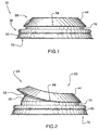
- FIGURE 1 a preferred embodiment of the closure of the present invention is illustrated and designated with general reference numeral 20.
- the closure 20 is for a container 22 having an aperture or open top bounded by a rim 26, such as a disposable coffee cup.
- a rim 26 such as a disposable coffee cup.
- the container 22 does not form part of the invention.
- the closure 20 comprises a substantially bowl-shaped body 28.
- the body 28 has an interior surface 30, best seen in FIGURE 4, and an exterior surface 32 and has defined therethrough a passage or aperture 34, as illustrated in FIGURE 2 and FIGURE 7.
- the closure 20 further comprises connection means for sealing the body 28 to the container 22 such that the interior surface 30 of the body 28, in combination with the container 22, defines an interior space 38 into which the aperture opens, as indicated in FIGURE 10.
- connection means is designated with general reference numeral 36 in FIGURE 1, and comprises a skirt 60 which extends peripherally around and is operatively connected to the body 28, the skirt 60 having a peripherally extending groove 70 therein, as indicated in FIGURE 4, shaped and dimensioned to frictionally, sealingly, releasably receive the rim 26.
- the body 28 When so sealed to the container 22, the body 28 may be selectively deformed, by manual manipulation, between a closed configuration, as illustrated in FIGURE 1, wherein the interior surface 30 is sealed against the aperture 34 to resist fluid flow, and an open configuration, as illustrated in FIGURE 10, wherein the passage or aperture 34 is in fluid communication with the interior space, to permit fluid flow.
- a pair of vent holes 58 are formed in the body 28 (actually, in an annular sheath part 44 of the body 28, described more fully in the following paragraph) on circumferentially opposite sides of the passage 34 to facilitate fluid egress, and avoid vacuum lock.
- the structure of the body 28 will now be described in more detail with reference to FIGURES 6 and 7, and will be seen to comprise a cap part 62, the aforementioned sheath part 44, an insert part 50, and an intermediate part 56.
- the sheath part 44 which has the passage 34 formed therein, has a first end 46 and a second end 48 and is frustoconical, tapering in external dimension towards the second end 48, which is occluded by and rigidly connected to the cap part 62.
- the insert part 50 also has a first end 52 and a second end 54, the second end 54 being shaped and dimensioned to be received within the sheath part 44.
- the intermediate part 56 extends between the first end 46 of the sheath part 44 and the second end 54 of the insert part 50, and flexibly connects same for relative movement, upon manual manipulation, from the open position, seen best in FIGURE 7, where the insert part 50 and the intermediate part 56 are disposed exteriorly relative to the sheath part 44, to the closed configuration, where the second end 54 of the insert part 50 (in fact, the entire insert part 50) is disposed, in substantially form-fitting, nested relation, within the intermediate part 56, and the intermediate part 56 is disposed, in substantially form-fitting, nested relation, within the sheath part 44, as indicated in FIGURE 6. It will be evident that during manual manipulation from the open configuration to the closed configuration, the intermediate part 56 collapses into the sheath part 44 and the second end 54 of the insert part 50 collapses into the intermediate part 56.
- the interior surface 30 is formed with a protuberance 42 which projects through the passage 34 in a sealing manner when the body 28 is in the closed configuration, as indicated in FIGURE 1 and FIGURE 6.
- the cap 62 forms an interiorly disposed protuberance having an outwardly tapering frustoconical sidewall 78 which, when the body 28 is in the closed configuration, sealingly engages against the junction of the intermediate part 56 and the insert part 50, so as to yet further increase the effectiveness of the seal.
- the open configuration is a static open configuration wherein the body 28 is stable without an external application of force
- the closed configuration is a static closed configuration wherein the body 28 is stable without an external application of force
- the body 28 is constructed of a resilient plastic and is of the "overcentre" variety, which is unstable at locations intermediate the open and closed position, and thus, self- biasing into one of the open and closed configuration, depending upon the relative locations of the various parts.
- a tubular pedestal part 74 is provided which rigidly extends between and connecting the first end 52 of the insert part 50 to the skirt 60, and the first end 52 of the insert part 50 is constructed of smaller external dimension than the first end 46 of the sheath part 44, thereby to define, in the closed configuration, an overhanging lip designated with general reference number 76 in FIGURE 6, which can be pried upwardly by the fingers of a user.
- the closure 20 may be constructed from the structure 68 illustrated in FIGURE 8 wherein each of the sheath part 44; intermediate part 56; and insert part 50 take the form of a substantially frustoconical annulus connected to one another (preferably, formed integrally) in alternating orientation.
- the intermediate part 56 is collapsed into the sheath part 44 and the insert part 50 collapsed into the intermediate part 56, and thereafter, the sheath part 44 is affixed, by sonic welding, adhesive or the like, to the insert part 50 at the side opposite to that in which the passage 34 is formed, so as to arrive at the preferred embodiment illustrated in FIGURE 9 (and FIGURE 1).
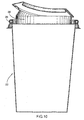
- FIGs 11 to 13 illustrate another embodiment of a closure suitable for use on a coffee cup, for example.
- This closure 82 is similar to the closure illustrated in Figures 8 and 9 of the drawings, except for the differences noted hereinafter.
- the closure 82 is shown mounted on the annular rim of a coffee cup 84.
- the closure 82 has an annular connection means as well for sealing its body to the cup, this connection means including a skirt 60 which is integrally connected to the body 84 of the closure.
- the skirt forms an annular groove 70 which is shaped and dimensioned to frictionally and sealingly receive the rim of the cup.
- a primary difference between the embodiment of Figures 11 to 13 and that of Figures 8 and 9 is the height of its tubular, pedestal part 88 which is substantially greater than the above described pedestal part 74.
- the height of the pedestal part 88 is in the range of 1 cm to 2 cm and it is most preferably close to 1 cm. Because of the greater height of the pedestal part 88, it can be easier for the user of this closure to manipulate the closure from the closed position illustrated in Figure 12 to the open position. It will be seen that in the closed position shown in Figure 12, the closure has an overhanging lip 76 which is spaced a substantial distance above an upper rim 90 of the closure.
- closure 82 is also provided with an insert part 50 visible in Figure 11 and the upper end of this part is integrally connected to an outwardly sloping intermediate part 56.
- the passage 34 of this closure is also formed in the sheath part 44.
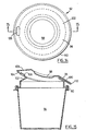
- FIG. 14 to 17 This closure is indicated generally at 92. Again, it will be understood that this embodiment is constructed generally in accordance with the embodiment of Figures 8 and 9 described above, except for the differences noted hereinafter.
- Figure 15 illustrates the closure 92 mounted on a cup 94 which can, for example, be a standard coffee cup.
- This closure is also fitted with means for connecting the body 96 of the closure to the cup, these means including the skirt 60 which extends peripherally around the bottom of the closure and which forms a groove to frictionally and sealingly receive the rim of the cup.
- the closure 92 includes an upper cap part 98, a downwardly sloping sheath part 100, an insert part 102 visible clearly in Figure 16, and an intermediate part 104.
- the sheath part 100 has a passage or hole 106 formed therein.
- a protuberance 108 is Formed on the intermediate part 104 which of course projects through the hole 106 when the body of the closure is in the closed position.
- this embodiment has an outwardly projecting, annular lip 110 which makes the closure easy to manipulate in order to move the closure from the fully closed position to the intermediate, open position of Figure 15.
- the lip 110 projects beyond the skirt 60 a short distance making it relatively easy for the user's thumb or finger to push the projecting lip upwardly in order to move the closure to the open position.
- tubular pedestal part 110 it is not necessary for the tubular pedestal part 110 to be as high as in the embodiment of Figures 11 and 12. In fact, this pedestal part 110 can be constructed with the same height as the embodiments of Figures 1 to 9.
- Figure 16 illustrates the preferred angle of slope of the insert part 102.
- the slope of the insert part 102 is approximately thirty degrees to the horizontal plane (assuming that the bottom of the closure is horizontal).
- the preferred slope of the intermediate part 104 is also about thirty degrees to the horizontal either in the closed position or in the fully opened position illustrated in Figure 16.
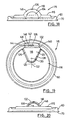
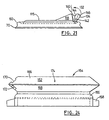
- closure suitable for a coffee cup or similar container is that illustrated in Figures 18 to 21 of the drawings.
- This closure does not form part of the present invention, but is described and illustrated herein for the purposes of a better understanding of the invention.
- This closure is indicated generally at 115.
- This closure has a primarily flat body 116 except for a relatively large, upwardly projecting protrusion 118.
- the closure 115 has means for connecting the body 116 to a container such as the container illustrated in Figure 10 and this connection means includes a skirt 60 which extends around the circumference of the body. As in the previous embodiments, this skirt forms a peripherally extending groove 70 which is shaped to frictionally and sealingly receive the cup rim.
- the aforementioned protrusion 118 can have a generally triangular shape in plan view as shown in Figure 19 with a rounded inner end at 120. This inner end can be located close to the centre 122 of the closure.
- the top surface 124 of the protrusion is rounded, forming a convex curve extending from one side 126 to an opposite side 128.
- a folding lip 132 integrally attached to the protrusion is a folding lip 132.
- This lip extends about the upper perimeter of a semi-circular front wall 134 which effectively closes the front side of the protrusion.
- a small hole 136 Formed in the upper extremity of the lip is a small hole 136 which, in the case of a coffee cup lid, can be a drinking hole.
- the protrusion is formed with an intermediate wall section 140 and the folding lip 132 is integrally connected to a front edge 142 of this wall section.
- the folding lip 132 includes a rear wall section 144 and a forward wall section 146 which are connected together along a fold line 148.
- the hole 136 is located along the fold line 148 and it extends only a short distance into the two wall sections 144, 146.
- FIGs 22 to 24 illustrate yet another form of a closure, being particularly suitable for use on a larger container such as paint can 152.
- the closure is designated generally by reference 154.
- This closure does not form a part of the present invention, but is described and illustrated herein for the better understanding of the invention.
- the illustrated paint can can be per se of known construction except for the construction of the illustrated closure.
- the can can be equipped with a handle 154 as illustrated but it will be understood that the closure 154 is equally suitable for a paint can having no handle.
- the can 152 is equipped with external connecting threads located at its top end 156. The threads themselves cannot be seen in Figure 22 as they are covered by the bottom portion of the closure 154. In any event, these threads are standard construction and they permit a threaded closure or top for the paint can to be detachably connected to the can in an efficient, sealable manner.
- closure 154 can be constructed in a manner similar to the closure illustrated in Figures 8 and 9 and described above.
- a primary difference of the closure 154 is that it is fitted with an internally threaded skirt at 156 that forms the bottom portion of the closure.
- the internal threads (not shown) are dimensioned and arranged to cooperate smoothly with the external threads formed on the top portion of the paint can.
- a preferred optional feature of this closure is that it is fitted with a skirt extension 158.
- the skirt extension may be formed with a rippled or corrugated outwardly facing wall that permits it to be easily gripped for turning purposes.
- the skirt extension extends radially beyond the annular lip 160 formed by the body 162 of the closure. In this way, the skirt extension is made easier to grip so that the closure can be readily turned about its vertical central axis.
- the closure 154 is constructed for a larger container such as a paint can, it will be understood that it is made of a thicker, stronger plastic sheet material. Suitable plastics that can be used include polypropylene and polyethylene. It will be understood that the plastic sheet material must be selected so that it has sufficient strength and rigidity to properly contain the paint within the can for all normal conditions of use.
- closure 154 Additional features of the closure 154 that can be seen in the figures include a circular top or cap part 164, a downwardly sloping sheath part 166 and an intermediate part 168.
- a suitable hole 170 is formed in one side of the sheath part. In the closed position shown in Figure 22, this hole can be sealed shut by means of a protuberance 172, this protuberance being formed on the intermediate part 168.
- Air holes 174 can be formed on opposite sides of the sheath part 166, if desired or necessary. If desired, protuberances can be provided on the intermediate part 168 to close sealingly the air holes 174 in the closed configuration.
- Figure 23 illustrates the closure 154 in an intermediate open position which allows paint (or any other liquid in the container) to flow out through the hole 170.
- the closure has been pried upwardly on one side only, that is on the side of the hole 170.
- the upper portion of the closure can be fully raised to the position illustrated in Figure 24. Movement of the closure to this position may be desirable, for example, for cleaning the lid. Particularly for a paint can lid, it can be important to clean off the interior of the lid so that it will function properly for future use purposes.
- connection means for sealing the body to the container in the preferred embodiment comprise a groove to receive the rim of the container
- the body and the container may, for example, be formed integrally, in which case the connection means will constitute a physical connection between the body and the container, and the rim will be a notional structure.
- the invention is not limited to beverage containers and paint cans, but may be utilized with equal utility in combination with other larger containers.
- the closure of the preferred embodiment is annular, and relatively "affixed" at one side the body may take other shapes, for example, rectangular, akin to an accordion, or polygonal, and may "open" from all sides.
- the structure illustrated in the preferred embodiment contemplates its construction from a precursor structure, it will be evident that such precursor structure is not necessary.
- sealing of the passage is effected by the interior surface, it is possible to seal the passage by the exterior surface, for example, by provision of an externally-projecting protuberance on the insert part, and by locating the passage through the intermediate part of the body.
Claims (16)
- Une fermeture pour un récipient ayant une ouverture limitée par un rebord, ladite fermeture comprenant :un corps en forme d'assiette (28) ayant une surface intérieure (30) et une surface extérieure (32) et au travers de celles-ci une ouverture définie (34) ; etun moyen de raccordement pour fermer de façon étanche le corps sur le récipient de sorte que la surface intérieure définit un espace intérieur (38) dans lequel l'ouverture dudit récipient s'ouvre pendant l'utilisation de ladite fermeture (20),ledit corps (28) est déformable sélectivement par manipulation manuelle entre une configuration ouverte, dans laquelle l'espace intérieur met le fluide en communication avec l'ouverture, et une configuration fermée dans laquelle une des surfaces intérieures et la surface extérieure sont fermées contre l'ouverture ; et dans laquelle :ledit corps possède un couvercle (62) ; une enveloppe annulaire (44) ayant une première extrémité (46) et une deuxième extrémité (48), cette dernière étant raccordée solidement au couvercle, caractérisée par le fait qu'un insert (50) ayant une première extrémité (52) et une deuxième extrémité (54), la forme et les dimensions de la deuxième extrémité de l'insert permettant d'entrer dans l'enveloppe; et une pièce intermédiaire (56) raccordée de façon mobile à la première extrémité de l'enveloppe et la deuxième extrémité de l'insert et s'étendant entre les deux.
- Une fermeture selon la revendication 1, suivant laquelle la configuration ouverte est une configuration ouverte statique dans laquelle le corps (28) est stable sans qu'une force extérieure ne soit appliquée.
- Une fermeture selon la revendication 2 dans laquelle la configuration fermée est une configuration fermée statique dans laquelle le corps (28) est stable sans qu'une force extérieure ne soit appliquée.
- Une fermeture selon la revendication 1 dans laquelle en configuration fermée, la surface intérieure (30) est fermée contre l'ouverture (34).
- Une fermeture selon la revendication 4 dans laquelle la surface intérieure définit une protubérance (42) débordant de l'ouverture (34) lorsque le corps (28) est en configuration fermée.
- Une fermeture selon l'une des revendications 1 à 5 dans laquelle ledit moyen de raccordement comprend un bord (60) qui s'étend en périphérie et est raccordé en relation active au corps, le bord ayant une rainure (70) s'étendant en périphérie qui est formée et dimensionnée pour recevoir ledit rebord (26) par friction afin d'assurer la fermeture et l'ouverture.
- Une fermeture selon la revendication 1 dans laquelle l'enveloppe annulaire (44) se rétrécit en dimension extérieure vers la deuxième extrémité (48).
- Une fermeture selon la revendication 1 dans laquelle, en configuration ouverte, l'insert (50) et la pièce intermédiaire (56) sont disposés au moins en partie en dehors de l'enveloppe (44), des sections de celle-ci adjacentes à ladite ouverture (34).
- Une fermeture selon la revendication 1 dans laquelle, après manipulation manuelle de la configuration ouverte à la configuration fermée, la pièce intermédiaire (56) est rabattue dans l'enveloppe (44) et l'insert (50) est rabattu dans la pièce intermédiaire (56).
- Une fermeture selon la revendication 9 dans laquelle, en configuration fermée, l'insert (50) s'engage parfaitement dans la pièce intermédiaire (56), et la pièce intermédiaire s'engage parfaitement dans l'enveloppe (44).
- Une fermeture selon la revendication 1 dans laquelle l'enveloppe (44) est essentiellement en forme de cône tronqué et se rétrécit vers ledit couvercle.
- Une fermeture selon la revendication 1, dans laquelle ladite ouverture (34) est formée au travers de l'enveloppe (44).
- Une fermeture selon la revendication 12, dans laquelle une paire d'orifices d'évent sont formés dans l'enveloppe (44) sur les côtés opposés en circonférence de ladite ouverture (34).
- Une fermeture selon la revendication 1, comprenant en outre un support tubulaire (88) s'étendant de façon rigide entre la première extrémité de l'insert (50) et le moyen de raccordement et reliant la première extrémité au moyen de raccordement comprenant un bord.
- Une fermeture selon la revendication 1, dans laquelle la dimension extérieure de la première extrémité (52) de l'insert (50) est plus petite que celle de la première extrémité (46) de l'enveloppe (44).
- Une fermeture selon la revendication 1, dans laquelle le couvercle forme une protubérance à l'intérieur qui s'engage contre la pièce intermédiaire pour assurer la fermeture étanche lorsque le corps est en configuration fermée.
Priority Applications (1)
| Application Number | Priority Date | Filing Date | Title |
|---|---|---|---|
| EP05023514A EP1619133B1 (fr) | 2001-10-24 | 2002-10-24 | Fermeture pour récipient |
Applications Claiming Priority (3)
| Application Number | Priority Date | Filing Date | Title |
|---|---|---|---|
| US33051701P | 2001-10-24 | 2001-10-24 | |
| US330517P | 2001-10-24 | ||
| PCT/CA2002/001602 WO2003035501A2 (fr) | 2001-10-24 | 2002-10-24 | Systeme de fermeture pour recipients |
Related Child Applications (1)
| Application Number | Title | Priority Date | Filing Date |
|---|---|---|---|
| EP05023514A Division EP1619133B1 (fr) | 2001-10-24 | 2002-10-24 | Fermeture pour récipient |
Publications (2)
| Publication Number | Publication Date |
|---|---|
| EP1448453A2 EP1448453A2 (fr) | 2004-08-25 |
| EP1448453B1 true EP1448453B1 (fr) | 2006-01-11 |
Family
ID=23290112
Family Applications (1)
| Application Number | Title | Priority Date | Filing Date |
|---|---|---|---|
| EP02801835A Expired - Lifetime EP1448453B1 (fr) | 2001-10-24 | 2002-10-24 | Systeme de fermeture pour recipients |
Country Status (8)
| Country | Link |
|---|---|
| US (2) | US7806289B2 (fr) |
| EP (1) | EP1448453B1 (fr) |
| AT (1) | ATE315528T1 (fr) |
| AU (1) | AU2002333132A1 (fr) |
| CA (1) | CA2503645A1 (fr) |
| DE (1) | DE60208723T2 (fr) |
| ES (1) | ES2256589T3 (fr) |
| WO (1) | WO2003035501A2 (fr) |
Families Citing this family (11)
| Publication number | Priority date | Publication date | Assignee | Title |
|---|---|---|---|---|
| WO2003035501A2 (fr) * | 2001-10-24 | 2003-05-01 | Jason Bruce Mccandlish | Systeme de fermeture pour recipients |
| GB0511081D0 (en) * | 2005-05-31 | 2005-07-06 | Carbonite Corp | Dispensing caps for liquid containers |
| US8342355B2 (en) * | 2008-02-12 | 2013-01-01 | Goade Ann M | Controlled flow drinking adapter and kit |
| US8322562B2 (en) * | 2008-04-30 | 2012-12-04 | Fine Line Contracting Corp. | Bellows beverage lid |
| TWM384844U (en) * | 2010-01-27 | 2010-07-21 | Qi-Rui Hong | Cup lid structure |
| US9883759B2 (en) | 2014-01-09 | 2018-02-06 | Goverre, Inc. | Closeable beverage lid |
| WO2018096503A1 (fr) * | 2016-11-25 | 2018-05-31 | Milton Innovations Limited | Couvercle pour récipient |
| US20180362228A1 (en) * | 2017-02-16 | 2018-12-20 | Jeffrey D. Jacobson | Container closure with integrated utensil |
| CN108720248A (zh) * | 2017-04-17 | 2018-11-02 | 瀛海国际股份有限公司 | 随行杯杯盖 |
| USD921423S1 (en) | 2019-08-29 | 2021-06-08 | Milton Innovations Limited | Lid for a container |
| US20240002114A1 (en) * | 2022-07-01 | 2024-01-04 | Comotomo 2022 Inc. | Container lid with integrated vent blocking mechanism |
Family Cites Families (10)
| Publication number | Priority date | Publication date | Assignee | Title |
|---|---|---|---|---|
| US795626A (en) * | 1905-02-02 | 1905-07-25 | Nelson Lampman | Cover for jars or analogous vessels. |
| US2218308A (en) * | 1939-06-08 | 1940-10-15 | Comer Burt | Bottle cap |
| US2698115A (en) * | 1950-03-31 | 1954-12-28 | Paley Phillips N | Collapsible paste tube or the like |
| US3321114A (en) * | 1966-03-04 | 1967-05-23 | Rexall Drug Chemical | Pop-up diaphragm closure |
| US3658217A (en) * | 1970-01-12 | 1972-04-25 | Phillips Petroleum Co | Weight-opening dispenser |
| USRE32927E (en) * | 1983-10-31 | 1989-05-23 | Reynolds Metals Company | Resealable container closure |
| US5240154A (en) * | 1991-06-14 | 1993-08-31 | Al Van Den Berghe | Closure system for a container employing a bellows member |
| US5597096A (en) * | 1996-02-15 | 1997-01-28 | Dart Industries Inc. | Shaker for condiments |
| US6419105B1 (en) * | 2000-09-26 | 2002-07-16 | Bruce-Warrer Development Corporation | Spill resistant lid with openable and closeable drinking opening |
| WO2003035501A2 (fr) * | 2001-10-24 | 2003-05-01 | Jason Bruce Mccandlish | Systeme de fermeture pour recipients |
-
2002
- 2002-10-24 WO PCT/CA2002/001602 patent/WO2003035501A2/fr not_active Application Discontinuation
- 2002-10-24 ES ES02801835T patent/ES2256589T3/es not_active Expired - Lifetime
- 2002-10-24 AU AU2002333132A patent/AU2002333132A1/en not_active Abandoned
- 2002-10-24 AT AT02801835T patent/ATE315528T1/de not_active IP Right Cessation
- 2002-10-24 EP EP02801835A patent/EP1448453B1/fr not_active Expired - Lifetime
- 2002-10-24 DE DE60208723T patent/DE60208723T2/de not_active Expired - Lifetime
- 2002-10-24 CA CA002503645A patent/CA2503645A1/fr not_active Abandoned
- 2002-10-24 US US10/493,335 patent/US7806289B2/en active Active
-
2010
- 2010-08-24 US US12/861,920 patent/US20110036851A1/en not_active Abandoned
Also Published As
| Publication number | Publication date |
|---|---|
| AU2002333132A1 (en) | 2003-05-06 |
| ES2256589T3 (es) | 2006-07-16 |
| WO2003035501A3 (fr) | 2004-01-29 |
| WO2003035501A2 (fr) | 2003-05-01 |
| EP1448453A2 (fr) | 2004-08-25 |
| DE60208723T2 (de) | 2006-09-28 |
| CA2503645A1 (fr) | 2003-05-01 |
| US20070164025A1 (en) | 2007-07-19 |
| US7806289B2 (en) | 2010-10-05 |
| DE60208723D1 (de) | 2006-04-06 |
| ATE315528T1 (de) | 2006-02-15 |
| US20110036851A1 (en) | 2011-02-17 |
Similar Documents
| Publication | Publication Date | Title |
|---|---|---|
| US20110036851A1 (en) | Container closure | |
| EP1788914B1 (fr) | Contenant anti-fuite | |
| US4925055A (en) | Container with unitary bladder and associated dispenser cap | |
| US8561834B2 (en) | Container lid and holder assembly, system and method | |
| EP1841662B1 (fr) | Gobelet anti-fuite | |
| US6176384B1 (en) | Spill-proof snack container | |
| US7100790B2 (en) | Spill-resistant metered flow cap for a cup | |
| US7686183B2 (en) | Container lid and holder and system and method for attaching a lid and holder to a container | |
| CA2197416C (fr) | Saupoudreuse pour epices | |
| US20070039960A1 (en) | Spill-Resistant Reclosable Closure Assembly for a Lid | |
| AU632810B2 (en) | A container | |
| US5018635A (en) | Fluid containment and access device for a beverage container | |
| AU2002357706A2 (en) | Recloseable lid with closure plug | |
| WO2008030767A2 (fr) | Fermeture aérée pour récipient | |
| US20100294765A1 (en) | Leak resistant drinking cup | |
| US20060249521A1 (en) | Spill-resistant container | |
| EP1619133B1 (fr) | Fermeture pour récipient | |
| KR100749826B1 (ko) | 밀폐용기 | |
| CA2327897C (fr) | Contenant pour aliments a l'epreuve des renversements accidentels | |
| KR20220168474A (ko) | 분리 배출이 가능한 용기용 원터치 캡 | |
| JPH1035702A (ja) | 飲料用容器のキャップ |
Legal Events
| Date | Code | Title | Description |
|---|---|---|---|
| PUAI | Public reference made under article 153(3) epc to a published international application that has entered the european phase |
Free format text: ORIGINAL CODE: 0009012 |
|
| AK | Designated contracting states |
Kind code of ref document: A2 Designated state(s): AT BE BG CH CY CZ DE DK EE ES FI FR GB GR IE IT LI LU MC NL PT SE SK TR |
|
| AX | Request for extension of the european patent |
Extension state: AL LT LV MK RO SI |
|
| 17P | Request for examination filed |
Effective date: 20040723 |
|
| 17Q | First examination report despatched |
Effective date: 20041011 |
|
| GRAP | Despatch of communication of intention to grant a patent |
Free format text: ORIGINAL CODE: EPIDOSNIGR1 |
|
| GRAS | Grant fee paid |
Free format text: ORIGINAL CODE: EPIDOSNIGR3 |
|
| GRAA | (expected) grant |
Free format text: ORIGINAL CODE: 0009210 |
|
| AK | Designated contracting states |
Kind code of ref document: B1 Designated state(s): AT BE BG CH CY CZ DE DK EE ES FI FR GB GR IE IT LI LU MC NL PT SE SK TR |
|
| PG25 | Lapsed in a contracting state [announced via postgrant information from national office to epo] |
Ref country code: IT Free format text: LAPSE BECAUSE OF FAILURE TO SUBMIT A TRANSLATION OF THE DESCRIPTION OR TO PAY THE FEE WITHIN THE PRESCRIBED TIME-LIMIT;WARNING: LAPSES OF ITALIAN PATENTS WITH EFFECTIVE DATE BEFORE 2007 MAY HAVE OCCURRED AT ANY TIME BEFORE 2007. THE CORRECT EFFECTIVE DATE MAY BE DIFFERENT FROM THE ONE RECORDED. Effective date: 20060111 Ref country code: NL Free format text: LAPSE BECAUSE OF FAILURE TO SUBMIT A TRANSLATION OF THE DESCRIPTION OR TO PAY THE FEE WITHIN THE PRESCRIBED TIME-LIMIT Effective date: 20060111 Ref country code: BE Free format text: LAPSE BECAUSE OF FAILURE TO SUBMIT A TRANSLATION OF THE DESCRIPTION OR TO PAY THE FEE WITHIN THE PRESCRIBED TIME-LIMIT Effective date: 20060111 Ref country code: CH Free format text: LAPSE BECAUSE OF FAILURE TO SUBMIT A TRANSLATION OF THE DESCRIPTION OR TO PAY THE FEE WITHIN THE PRESCRIBED TIME-LIMIT Effective date: 20060111 Ref country code: SK Free format text: LAPSE BECAUSE OF FAILURE TO SUBMIT A TRANSLATION OF THE DESCRIPTION OR TO PAY THE FEE WITHIN THE PRESCRIBED TIME-LIMIT Effective date: 20060111 Ref country code: LI Free format text: LAPSE BECAUSE OF FAILURE TO SUBMIT A TRANSLATION OF THE DESCRIPTION OR TO PAY THE FEE WITHIN THE PRESCRIBED TIME-LIMIT Effective date: 20060111 Ref country code: AT Free format text: LAPSE BECAUSE OF FAILURE TO SUBMIT A TRANSLATION OF THE DESCRIPTION OR TO PAY THE FEE WITHIN THE PRESCRIBED TIME-LIMIT Effective date: 20060111 Ref country code: FI Free format text: LAPSE BECAUSE OF FAILURE TO SUBMIT A TRANSLATION OF THE DESCRIPTION OR TO PAY THE FEE WITHIN THE PRESCRIBED TIME-LIMIT Effective date: 20060111 |
|
| REG | Reference to a national code |
Ref country code: CH Ref legal event code: EP |
|
| REG | Reference to a national code |
Ref country code: IE Ref legal event code: FG4D |
|
| REF | Corresponds to: |
Ref document number: 60208723 Country of ref document: DE Date of ref document: 20060406 Kind code of ref document: P |
|
| PG25 | Lapsed in a contracting state [announced via postgrant information from national office to epo] |
Ref country code: DK Free format text: LAPSE BECAUSE OF FAILURE TO SUBMIT A TRANSLATION OF THE DESCRIPTION OR TO PAY THE FEE WITHIN THE PRESCRIBED TIME-LIMIT Effective date: 20060411 Ref country code: SE Free format text: LAPSE BECAUSE OF FAILURE TO SUBMIT A TRANSLATION OF THE DESCRIPTION OR TO PAY THE FEE WITHIN THE PRESCRIBED TIME-LIMIT Effective date: 20060411 Ref country code: BG Free format text: LAPSE BECAUSE OF FAILURE TO SUBMIT A TRANSLATION OF THE DESCRIPTION OR TO PAY THE FEE WITHIN THE PRESCRIBED TIME-LIMIT Effective date: 20060411 |
|
| RAP2 | Party data changed (patent owner data changed or rights of a patent transferred) |
Owner name: MCCANDLISH, JASON BRUCE |
|
| RIN2 | Information on inventor provided after grant (corrected) |
Inventor name: TAYLOR, KENNETH, SHEPPARD, ALBERT Inventor name: MCCANDLISH, JASON, BRUCE |
|
| PG25 | Lapsed in a contracting state [announced via postgrant information from national office to epo] |
Ref country code: PT Free format text: LAPSE BECAUSE OF FAILURE TO SUBMIT A TRANSLATION OF THE DESCRIPTION OR TO PAY THE FEE WITHIN THE PRESCRIBED TIME-LIMIT Effective date: 20060612 |
|
| NLT2 | Nl: modifications (of names), taken from the european patent patent bulletin |
Owner name: MCCANDLISH, JASON BRUCE Effective date: 20060503 |
|
| NLV1 | Nl: lapsed or annulled due to failure to fulfill the requirements of art. 29p and 29m of the patents act | ||
| REG | Reference to a national code |
Ref country code: ES Ref legal event code: FG2A Ref document number: 2256589 Country of ref document: ES Kind code of ref document: T3 |
|
| REG | Reference to a national code |
Ref country code: CH Ref legal event code: PL |
|
| ET | Fr: translation filed | ||
| PG25 | Lapsed in a contracting state [announced via postgrant information from national office to epo] |
Ref country code: IE Free format text: LAPSE BECAUSE OF NON-PAYMENT OF DUE FEES Effective date: 20061024 |
|
| PG25 | Lapsed in a contracting state [announced via postgrant information from national office to epo] |
Ref country code: MC Free format text: LAPSE BECAUSE OF NON-PAYMENT OF DUE FEES Effective date: 20061031 |
|
| PLBE | No opposition filed within time limit |
Free format text: ORIGINAL CODE: 0009261 |
|
| STAA | Information on the status of an ep patent application or granted ep patent |
Free format text: STATUS: NO OPPOSITION FILED WITHIN TIME LIMIT |
|
| 26N | No opposition filed |
Effective date: 20061012 |
|
| PG25 | Lapsed in a contracting state [announced via postgrant information from national office to epo] |
Ref country code: GR Free format text: LAPSE BECAUSE OF FAILURE TO SUBMIT A TRANSLATION OF THE DESCRIPTION OR TO PAY THE FEE WITHIN THE PRESCRIBED TIME-LIMIT Effective date: 20060412 Ref country code: CZ Free format text: LAPSE BECAUSE OF FAILURE TO SUBMIT A TRANSLATION OF THE DESCRIPTION OR TO PAY THE FEE WITHIN THE PRESCRIBED TIME-LIMIT Effective date: 20060111 |
|
| PG25 | Lapsed in a contracting state [announced via postgrant information from national office to epo] |
Ref country code: EE Free format text: LAPSE BECAUSE OF FAILURE TO SUBMIT A TRANSLATION OF THE DESCRIPTION OR TO PAY THE FEE WITHIN THE PRESCRIBED TIME-LIMIT Effective date: 20060111 |
|
| PG25 | Lapsed in a contracting state [announced via postgrant information from national office to epo] |
Ref country code: TR Free format text: LAPSE BECAUSE OF FAILURE TO SUBMIT A TRANSLATION OF THE DESCRIPTION OR TO PAY THE FEE WITHIN THE PRESCRIBED TIME-LIMIT Effective date: 20060111 Ref country code: LU Free format text: LAPSE BECAUSE OF NON-PAYMENT OF DUE FEES Effective date: 20061024 |
|
| PG25 | Lapsed in a contracting state [announced via postgrant information from national office to epo] |
Ref country code: CY Free format text: LAPSE BECAUSE OF FAILURE TO SUBMIT A TRANSLATION OF THE DESCRIPTION OR TO PAY THE FEE WITHIN THE PRESCRIBED TIME-LIMIT Effective date: 20060111 |
|
| PGFP | Annual fee paid to national office [announced via postgrant information from national office to epo] |
Ref country code: ES Payment date: 20100429 Year of fee payment: 8 Ref country code: FR Payment date: 20100521 Year of fee payment: 8 |
|
| PGFP | Annual fee paid to national office [announced via postgrant information from national office to epo] |
Ref country code: DE Payment date: 20100430 Year of fee payment: 8 Ref country code: IT Payment date: 20100430 Year of fee payment: 8 |
|
| PG25 | Lapsed in a contracting state [announced via postgrant information from national office to epo] |
Ref country code: FR Free format text: LAPSE BECAUSE OF NON-PAYMENT OF DUE FEES Effective date: 20101102 |
|
| REG | Reference to a national code |
Ref country code: FR Ref legal event code: ST Effective date: 20110630 |
|
| REG | Reference to a national code |
Ref country code: DE Ref legal event code: R119 Ref document number: 60208723 Country of ref document: DE Effective date: 20110502 |
|
| REG | Reference to a national code |
Ref country code: ES Ref legal event code: FD2A Effective date: 20111121 |
|
| PG25 | Lapsed in a contracting state [announced via postgrant information from national office to epo] |
Ref country code: IT Free format text: LAPSE BECAUSE OF NON-PAYMENT OF DUE FEES Effective date: 20101024 |
|
| PG25 | Lapsed in a contracting state [announced via postgrant information from national office to epo] |
Ref country code: ES Free format text: LAPSE BECAUSE OF NON-PAYMENT OF DUE FEES Effective date: 20101025 |
|
| PGFP | Annual fee paid to national office [announced via postgrant information from national office to epo] |
Ref country code: GB Payment date: 20120430 Year of fee payment: 10 |
|
| GBPC | Gb: european patent ceased through non-payment of renewal fee |
Effective date: 20121024 |
|
| PG25 | Lapsed in a contracting state [announced via postgrant information from national office to epo] |
Ref country code: DE Free format text: LAPSE BECAUSE OF NON-PAYMENT OF DUE FEES Effective date: 20110502 |
|
| PG25 | Lapsed in a contracting state [announced via postgrant information from national office to epo] |
Ref country code: GB Free format text: LAPSE BECAUSE OF NON-PAYMENT OF DUE FEES Effective date: 20121024 |