EP1448006A2 - Drahtloses Netz mit intensiver Frequenzwiederholung - Google Patents
Drahtloses Netz mit intensiver Frequenzwiederholung Download PDFInfo
- Publication number
- EP1448006A2 EP1448006A2 EP04075437A EP04075437A EP1448006A2 EP 1448006 A2 EP1448006 A2 EP 1448006A2 EP 04075437 A EP04075437 A EP 04075437A EP 04075437 A EP04075437 A EP 04075437A EP 1448006 A2 EP1448006 A2 EP 1448006A2
- Authority
- EP
- European Patent Office
- Prior art keywords
- node
- nodes
- antenna
- signal
- antennas
- Prior art date
- Legal status (The legal status is an assumption and is not a legal conclusion. Google has not performed a legal analysis and makes no representation as to the accuracy of the status listed.)
- Withdrawn
Links
Images


Classifications
-
- H—ELECTRICITY
- H04—ELECTRIC COMMUNICATION TECHNIQUE
- H04W—WIRELESS COMMUNICATION NETWORKS
- H04W16/00—Network planning, e.g. coverage or traffic planning tools; Network deployment, e.g. resource partitioning or cells structures
- H04W16/24—Cell structures
- H04W16/28—Cell structures using beam steering
-
- H—ELECTRICITY
- H04—ELECTRIC COMMUNICATION TECHNIQUE
- H04B—TRANSMISSION
- H04B7/00—Radio transmission systems, i.e. using radiation field
- H04B7/02—Diversity systems; Multi-antenna system, i.e. transmission or reception using multiple antennas
- H04B7/04—Diversity systems; Multi-antenna system, i.e. transmission or reception using multiple antennas using two or more spaced independent antennas
- H04B7/06—Diversity systems; Multi-antenna system, i.e. transmission or reception using multiple antennas using two or more spaced independent antennas at the transmitting station
- H04B7/0613—Diversity systems; Multi-antenna system, i.e. transmission or reception using multiple antennas using two or more spaced independent antennas at the transmitting station using simultaneous transmission
- H04B7/0615—Diversity systems; Multi-antenna system, i.e. transmission or reception using multiple antennas using two or more spaced independent antennas at the transmitting station using simultaneous transmission of weighted versions of same signal
- H04B7/0617—Diversity systems; Multi-antenna system, i.e. transmission or reception using multiple antennas using two or more spaced independent antennas at the transmitting station using simultaneous transmission of weighted versions of same signal for beam forming
-
- H—ELECTRICITY
- H04—ELECTRIC COMMUNICATION TECHNIQUE
- H04B—TRANSMISSION
- H04B7/00—Radio transmission systems, i.e. using radiation field
- H04B7/02—Diversity systems; Multi-antenna system, i.e. transmission or reception using multiple antennas
- H04B7/04—Diversity systems; Multi-antenna system, i.e. transmission or reception using multiple antennas using two or more spaced independent antennas
- H04B7/08—Diversity systems; Multi-antenna system, i.e. transmission or reception using multiple antennas using two or more spaced independent antennas at the receiving station
- H04B7/0837—Diversity systems; Multi-antenna system, i.e. transmission or reception using multiple antennas using two or more spaced independent antennas at the receiving station using pre-detection combining
- H04B7/0842—Weighted combining
- H04B7/0848—Joint weighting
- H04B7/0854—Joint weighting using error minimizing algorithms, e.g. minimum mean squared error [MMSE], "cross-correlation" or matrix inversion
Definitions
- the present invention relates generally to wireless communications, and specifically to methods and systems for frequency reuse in wireless networks.
- Wireless backhaul networks are commonly used for trunking between network access points and switches, as well as among the switches themselves.
- wireless backhaul links may connect base transmission stations (BTS) to base station controllers (BSC), and may similarly connect BSCs to the mobile switching center (MSC).
- BTS base transmission stations
- BSC base station controllers
- MSC mobile switching center
- These wireless links may make up the entire backhaul network, or they may alternatively be used in conjunction with high-speed terrestrial links.
- a variety of different backhaul network topologies are known in the art, including ring, star and mesh topologies.
- Wireless links in a backhaul network are typically implemented using directional microwave antennas, over line-of-sight paths between the nodes.
- each of the nodes has at least one antenna that is aimed toward the other node in the pair.
- each node may actually use multiple antennas for each of its links.
- Interference between different links must typically be held below some predefined level.
- the line-of-sight paths of different links are far apart in angle, the directional properties of the antennas can provide the required interference rejection even when the links operate on the same frequency.
- Adaptive cancellation can also be used to increase channel capacity in wireless communication networks.
- U.S. Patent 6,289,004 whose disclosure is incorporated herein by reference, describes an adaptive interference canceller system, which cancels the effects of known, fixed interference sources in signals that it receives.
- the system includes a main antenna for receiving signals from other communication stations and one or more directional antennas, which are directed toward interference sources.
- the adaptive canceller weights the signals received by the directional antennas and sums the weighted signals to produce a cancellation signal.
- the cancellation signal is subtracted from the signal received by the main antenna to provide an output that is said to be substantially free from the interference generated by the known interference sources.
- Embodiments of the present invention provide methods and systems of signal processing for suppressing interference among different links in wireless networks. These methods and systems enable enhanced frequency reuse among the different links.
- At least one node in a communication network has multiple wireless links connecting it to other nodes in the network.
- the node comprises multiple antennas, each of which is associated with a. respective link.
- the links are line-of-sight radio links, and the antennas are directional antennas, each of which is aimed toward a corresponding antenna at the other end of the respective link.
- the node further comprises signal processing circuitry, which combine the signals transmitted and received by the different antennas in order to cancel interference between the different links. Two complementary methods are used for interference cancellation:
- the methods of the present invention enable cancellation of interference even between links that are close together in angle. Therefore, neighboring antennas can use the same frequency band, unlike systems known in the art, and it is typically possible for all the links over which a given node receives or transmits signals to operate in the same frequency band. (For frequency division duplex (FDD) operation, it may be desirable to use one band at each node for transmission and a different band for reception.) This enhancement of frequency reuse can be achieved substantially without modification to existing antenna infrastructure, simply by applying the signal processing methods provided by the present invention.
- FDD frequency division duplex
- Frequency reuse schemes based on the present invention may be employed in various different network topologies, including ring, mesh, star and other types of point-to-multipoint networks.
- Embodiments of the present invention are particularly useful in reducing the bandwidth requirements of wireless networks in which the positions of the nodes are fixed, such as in backhaul networks, for example.
- the principles of the present invention may be applied in substantially any sort of radio communication network.
- a receiver for use in a wireless network including:
- the first and second signals are transmitted in a common frequency channel.
- the processing circuitry may be further adapted to extract the second stream of digital information from the receiver inputs while suppressing a second interference due to the reception of the first signal by the second antenna.
- the processing circuitry is adapted to estimate an error in the extracted stream of digital information, to determine coefficients in response to the estimated error, and to apply the coefficients to the first and second receiver inputs in order to suppress the interference.
- the processing circuit is adapted to determine the coefficients so as to minimize a mean square of the error.
- the processing circuitry is adapted to adjust the coefficients adaptively, in response to a change in a channel transfer function between at least one of the first and second transmitters and at least one of the first and second antennas.
- the first and second signals include multi-carrier signals
- the processing circuitry is adapted to divide the first and second receiver inputs into multiple frequency components, and to determine the coefficients to be applied individually to each of the frequency components.
- the first and second signals includes single-carrier signals
- the processing circuitry includes a tap-delay channel equalizer
- the receiver includes a plurality of N antennas, including the first and second antennas
- the processing circuitry is adapted to combine the receiver inputs from the N antennas so as to extract the first stream of digital information while suppressing up to N-1 interferers, including the first interference.
- the N-1 interferers may include at least one interference source that is not a transmitter in the wireless network.
- a transmitter for use in a wireless network including:
- the signal generation circuit is adapted to generate the first and second signals for transmission in a common frequency channel.
- the signal generation circuitry may be further adapted to generate the first and second signals so that a second interference associated with the transmission of the first signal is suppressed at the second receiver.
- the signal generation circuitry is adapted to determine a channel transfer function between the first and second antennas and at least one of the first and second receivers, to determine coefficients based on the channel transfer function, and to apply the coefficients to the first and second streams of digital information in order to generate the first and second signals so as to suppress the interference.
- the signal generation circuitry is adapted to generate training signals for transmission to the first and second receivers, for use in determining the channel transfer function.
- the transmitter may include a return channel receiver, for receiving data associated with the coefficients from the first and second receivers in response to reception of the training signals at the first and second receivers.
- the first and second signals include multi-carrier signals
- the signal generation circuitry is adapted to generate multiple frequency components of the signals, and to determine the coefficients to be applied individually to each of the frequency components.
- the first and second signals include single-carrier signals, and wherein the signal generation circuitry includes a tap-delay channel pre-equalizer.
- the transmitter includes a plurality of M antennas, including the first and second antennas
- the signal generation circuitry is adapted to combine up to M streams of digital information so as to generate up to M signals for transmission respectively by the M antennas, such that up to M-1 interferers due to the transmission of the up to M signals, including the first interference, are suppressed at the first receiver.
- communication apparatus for use in a wireless network, including:
- a wireless communication network including a plurality of nodes, which include at least first and second nodes, wherein each of the first and second nodes includes a respective first antenna, such that the first antenna of the first node is directed to transmit a first signal toward the second node, and the first antenna of the second node is directed toward the first node so as to receive the first signal, and wherein at least the first node includes a respective second antenna, which is directed toward another of the nodes in the network, and wherein the first node includes signal generation circuitry, which is coupled to receive a first stream of digital information to be conveyed to the second node and a second stream of digital information to be conveyed to another of the nodes, and wherein the signal generation circuitry is adapted to combine the first and second streams of digital information so as to generate the first signal and to generate a second signal for transmission by the second antenna of the first node, such that at least a first interference due to the transmission of the second signal is
- the second node includes a respective second antenna and processing circuitry, which is coupled to receive first and second receiver inputs from the first and second antennas of the second node, respectively, due to reception by the antennas of the second node of the first signal and of at least a third signal transmitted from another of the nodes in the network, and the processing circuitry is adapted to combine the first and second receiver inputs so as to extract at least the first stream of digital information from the receiver inputs while suppressing at least a second interference due to reception of the third signal by the first antenna of the second node.
- the first and second nodes may be adapted to suppress at least the first and second interferences substantially without dependence on synchronization between the nodes in the network.
- At least a first subset of the nodes are arranged in a ring topology. At least one of the nodes in the first subset may be connected by a wireless link to another one of the nodes in a second subset of the nodes, which are not a part of the ring topology of the first subset.
- the nodes are arranged in a mesh topology.
- the nodes are arranged in a star topology, and the first node is located at a hub of the star topology.
- the signal generation circuitry may be adapted to generate the first and second signals in accordance with a multiplexing scheme, so that multiple nodes in the network, including the second node, are served by the first antenna of the first node.
- the multiplexing scheme is typically selected from a group of schemes consisting of TDMA and CDMA.
- a wireless communication network including a plurality of nodes, which include at least first and second nodes, wherein each of the first and second nodes includes a respective first antenna, such that the first antenna of the first node is directed to transmit a first signal carrying a first stream of digital information toward the second node, and the first antenna of the second node is directed toward the first node so as to receive the first signal, and wherein at least the second node includes a second antenna, which is directed toward another of the nodes in the network, and wherein the second node includes processing circuitry, which is coupled to receive first and second receiver inputs from the first and second antennas of the second node, respectively, due to reception by the antennas of the second node of the first signal and of at least a second signal transmitted from another of the nodes in the network, and wherein the processing circuitry is adapted to combine the first and second receiver inputs so as to extract at least the first stream of digital information from the receiver inputs while suppressing
- the nodes are arranged in a star topology, and the second node is located at a hub of the star topology.
- the processing circuitry may be adapted to receive the first and second receiver inputs in accordance with a multiplexing scheme, so that multiple nodes in the network, including the first node, are served by the first antenna of the second node, wherein the multiplexing scheme is typically selected from a group of schemes consisting of TDMA, CDMA and ALOHA.
- a method for processing the first and second signals at the receiving node including:
- a transmitting node has a first antenna directed toward a first receiver positioned in a first location, and a second antenna directed toward a second receiver positioned in a second location, separated from the first location, a method for generating signals for transmission by the transmitting node, including:
- Fig. 1 is a schematic, pictorial illustration of a cellular communication network 20, in accordance with an embodiment of the present invention.
- Network 20 comprises a MSC 22, which is connected by wireless links to BSCs 24.
- the MSC and the two BSCs shown in Fig. 1 define a wireless ring network, which is used for backhaul communications between these elements of cellular network 20.
- Each of the nodes in this ring network i.e., the MSC and the two BSCs
- Each pair of an east antenna 32 on one node and a corresponding west antenna 34 on another node defines a communication link, which is typically a duplex, line-of-sight, microwave link.
- a communication link typically a duplex, line-of-sight, microwave link.
- the principles of the present invention may similarly be applied to simplex links, and to radio links of other types.
- MSC 22 is typically connected to a public switched telephone network (PSTN) 26.
- PSTN public switched telephone network
- This connection is shown in the figure as a terrestrial link, typically carried by a high-speed wire or fiberoptic cable.
- MSC 22 may also be connected to PSTN 26 by a wireless link.
- the other links in network 20 are shown as wireless links, some of these links may be replaced by terrestrial wired links.
- Each BSC 24 is typically connected to one or more BTSs 28, which in turn communicate with mobile units 30.
- one BSC 24 is connected by wireless links in a star topology to two BTSs 28.
- the BSC comprises antennas 36 and 38 for communicating with antennas 39 of the BTSs.
- the links between the BSC antennas and the BTS antennas are also duplex (FDD or TDD), line-of-sight, microwave links.
- Fig. 1 is a highly-simplified representation of a cellular network and of certain elements in the network, which is shown here in order to exemplify topologies that are generally used in wireless backhaul networks.
- the ring and star topologies shown in the figure each include only a few nodes, larger numbers of nodes may be used in practice, and the principles of the present invention are equally applicable to larger, more complex networks.
- each link shown in the figures is served by only a single antenna at each end, each antenna 32, 34, 36, 38 or 39 may in practice comprise an array of antennas.
- the antennas in each such array may be arranged to provide desired directional characteristics and/or spatial diversity, in conjunction with suitable beam-forming circuits.
- the beam-forming circuits used for spatial processing on each wireless link of network 20 may be of any suitable type known in the art.
- the antenna arrays and beam-forming circuits may be adapted to enhance the capacity and reliability of links in network 20 by means of near-field spatial multiplexing, as described in U.S. Provisional Patent Application 60/356,985, filed February 13, 2002, and in PCT Patent Application PCT/IL03/00108, filed February 12, 2003.
- an antenna array that serves a single link may be regarded as a single antenna for the purpose of the description that follows.
- Fig. 2 is a schematic top view of a portion of a wireless communication network, such as network 20, illustrating signals transmitted among nodes 40 in this network, in accordance with an embodiment of the present invention.
- nodes 40 shown in Fig. 2 may be connected together as a part of a ring network, in the manner of MSC 22 and BSCs 24, as shown in Fig. 1.
- Nodes 40 are identified for convenience in Fig. 2 as NODE 1, NODE 2 and NODE 3, and the signals received by NODE 3 are considered in this figure and in the description that follows. It is assumed, for the sake of this example, that all the antennas of NODE 1 and NODE 2 transmit signals on the same frequency channel.
- East antenna 32 of NODE 3 receives one desired signal, S 13 , from west antenna 34 of NODE 1, while west antenna 34 of NODE 3 receives another signal S 23 from east antenna 32 NODE 2.
- each antenna of NODE 3 receives interfering signals: I 23W and I 13W at west antenna 34, and I 23E and I 13E at east antenna 32.
- a transmitting node with N antennas will transmit N-1 interfering signals to each of its neighboring receivers, which may be cancelled by signal generation circuitry in each transmitter, as described hereinbelow.
- a receiving node with M neighbors, each equipped with a transmitting interference canceller will face M-1 interferers, which may be cancelled by signal processing circuitry in the receiver.
- the maximum number of interfering signals that can be canceled by a given node is determined by the number of antennas connected to the node and the number of transmitting antennas in the neighboring nodes. In practice, however, significant interfering signals are typically received only from nearby transmitting antennas whose transmitted beams cover the receiving antenna location, or whose locations fall within the angular receiving beam of the receiving antenna.
- Interfering signals from other antennas positions are generally too weak to affect the quality of communications on the network link in question. Therefore, in the present embodiment, some interfering signals are neglected, such as the interfering signal from west antenna 34 of NODE 2 to east antenna 32 of NODE 3, for example.
- the transmitter circuits associated with the different antennas are mutually synchronized and operate at the same frequency, i.e., they share a common oscillator and have the same symbol clock and signal generation timing.
- the receivers in each node are mutually synchronized, sharing a common oscillator and sample timing.
- the receiver interference cancellation capabilities are not required for canceling interferers within network 20, some of the interfering signals may even come from outside the network.
- stranger interferers
- Fig. 3 is a block diagram that schematically shows signal processing elements used in the network of Fig. 2, in accordance with an embodiment of the present invention.
- Each of antennas 32 and 34 receives signals from multiple transmitting antennas, with amplitude and phase determined by a complex channel transfer function matrix H, which relates the transmitted signal vector x' and the received signal vector y' .
- H can be separated into H s for the desired signal and H i for the interfering signals.
- H s has elements H ij , corresponding to the transfer of the desired signal, S ij , between the transmitting and receiving antennas on each link.
- H i has elements H ijW and H ijE corresponding to the interferers I ijW and I ijE .
- x' and y' include all the relevant signals and interferers.
- the transmitted signal vector x' corresponds to the four complex signals x ij ' transmitted by the antennas of NODE 1 and NODE 2, while the received signal vector y' corresponds to the two signals y ij ' received by the antennas of NODE 3.
- n the noise received at each antenna.
- x' [ x' 13 x' 12 x' 21 x' 23 ]
- y' [ y' 13 y' 23 ] T
- the elements of H represent generally both amplitude attenuation and relative phase delay in propagation of signals between the particular transmitting and receiving antennas.
- the amplitudes of the elements of H are assumed to be negligible except for the following elements:
- Nodes 40 comprise transmitter signal processing circuitry 41 (also referred to as signal generation circuitry) and receiver signal processing circuitry 45, whose purpose, inter alia, is to eliminate the interfering signals or, in other words, to cancel out the effect of I ij on the vector y.
- circuitry 41 cancels the impact of I 13E and I 23W on y'
- circuitry 45 cancels the impact of I 23E and I 13W on y'.
- the circuitry is shown conceptually in Fig. 3. Practical implementations will be apparent to those skilled in the art. Further details of one possible implementation of signal processing circuitry 45 are described hereinbelow with reference to Figs. 4 and 5.
- each node comprises both transmitter and receiver circuitry of the types shown here, but for simplicity, only the circuitry relevant to the signals received at NODE 3 is shown (i.e., transmitter circuitry 41 of NODE 1 and NODE 2 and receiver circuitry 45 of NODE 3) and described here.
- V [ V 1 V 2 ] T
- x [x 13 x 12 x 21 x 23 ] T
- the input signal vector x 2 ( x 21 , x 23 ) corresponds to the data streams received by circuitry 41 for transmission to NODE 1 and NODE 3, respectively.
- the elements of the vector x' represent the actual physical signals to be transmitted by each of antennas 32 and 34.
- V 2 is a 2 x 2 diagonal matrix, whose diagonal elements are unity, and whose off-diagonal elements correct for interference due to H 23W and H 13E .
- Matrix multiplication of x 2 by V 2 is represented by multiplication of x 21 and x 23 by the off-diagonal coefficients of V 2 , V 13 and V 31 , in multipliers 42, followed by summation in adders 44 to give the rotated signals x 21 ' and x 23 '.
- a similar operation takes place at NODE 1.
- the values of the elements of V are typically determined in a training procedure, as described further hereinbelow.
- n is ignored here, since the statistical behavior of the noise is substantially unaffected by the transformation U , which is nearly unitary.
- U is a 2 x 2 matrix, whose diagonal elements are unity, and whose off-diagonal coefficients correct for interference due to H 23E and H 13W :
- the elements of U may be determined adaptively, while communication traffic is transmitted over network 20, as described hereinbelow.
- Fig. 4 is a block diagram that schematically illustrates a portion of receiver circuitry 45, in accordance with an embodiment of the present invention.
- circuitry 45 is shown in this figure (with further details shown in Fig. 5) as being divided into certain functional blocks.
- the functions of these blocks may be carried out using dedicated hardware components, either off-shelf or custom, or by means of software running on a suitable programmable processor, or by a combination of hardware and software elements.
- the functions of at least some of the blocks shown in the figure may be carried out together by a single component, while the functions of other blocks may be divided among multiple components. Appropriate implementations for different application requirements will be apparent to those skilled in the art.
- Fig. 4 assumes that network 20 uses a multi-carrier modulation scheme (also known as a multi-tone modulation scheme), such as orthogonal frequency domain multiplexing (OFDM). Therefore, the off-diagonal coefficients U 21 and U 12 are determined and applied individually for each of the OFDM frequency sub-channels. (Only U 12 is relevant in the example shown in Fig. 4, which relates only to generation of decision data regarding the west antenna signal.) U 21 and U 12 can thus be treated simply as complex scalars, since delay spread over the wireless link between the transmitter and the receiver can be neglected within each of the sub-channels.
- OFDM orthogonal frequency domain multiplexing
- Fig. 4 shows a frequency-domain implementation of the present invention, the interference suppression functions of the present invention may similarly be carried out in the time domain.
- Signals received by antennas 32 and 34 are processed by RF receivers 50, as are known in the art, and are then converted to streams of digital samples 52 by analog/digital converters (ADC) 52.
- ADC analog/digital converters
- these samples correspond to y 13 ' and y 23 ' coming from the east and west antennas, respectively.
- the samples from both antennas are then passed to separate east and west processing channels. As the east and west channels are substantially identical, only the west channel is described here.
- Interpolators 54 correct the east and west sample streams for clock skew, based on symbol timing extracted by a timing circuit 58.
- FFT Fast Fourier Transform
- the FFT results of the west samples are used by timing circuit 58 to determine the timing correction to be applied to interpolators 54, as well as the appropriate synchronization of FFT processors 56.
- the operation of interpolators 54, FFT processors 56 and timing circuit 58 is well known in the OFDM art.
- the frequency-domain samples that are output by FFT processors 56 are amplitude- and phase-matched by interference canceller 60 to provide an interference-free stream of samples of the west data symbols, y 23.
- Canceller 60 operates on each of the frequency sub-channels of the OFDM signals individually.
- the values of U 21 and U 12 to be used in this operation are determined adaptively, for each sub-channel, by a coefficient controller 62, as described hereinbelow.
- An equalizer 64 corrects the interference free-signal for channel- and hardware-related distortion, and a common phase error (CPE) rotator 66 removes the common phase noise in each sub-channel.
- a slicer 70 generates decision data, providing an output data stream of data values, corresponding to the data transmitted by NODE 2.
- equalizer 64 The operations of equalizer 64, rotator 66 and slicer 70 are known in the art of OFDM receivers. Some or all of these operations may be combined in a single digital filtering step along with the operation of interference canceller 60. Furthermore, elements of the processing may be performed on groups of sub-carriers, depending of the extent of delay spread of the signal.
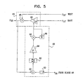
- Fig. 5 is a block diagram that schematically shows details of coefficient controller 62, along with elements of interference canceller 60, in accordance with an embodiment of the present invention.
- the coefficient controller carries out a least-mean-square (LMS) convergence procedure in order to adaptively determine and update the coefficient U 12 that is applied by multiplier 46 in interference canceller 60.
- the LMS procedure is performed individually for different OFDM sub-channels (or groups of sub-channels), and Fig. 5 illustrates the LMS loop used for a single sub-channel.
- the LMS procedure may be carried out for every one of the sub-channels.
- the LMS procedure may be carried out only for selected sub-channels, with the coefficients of the remaining sub-channels determined by interpolation, as long as the sub-carrier to sub-carrier phase and amplitude variations are not too great.
- other coefficient adaptation procedures as are known in the art, may be used to determine the interference cancellation coefficients.
- Coefficient controller 62 receives as its inputs the interference-canceled sample y 23 output by the interference canceller for carrier k, along with an error signal e 23 for this carrier, which is provided by an equalizer/CPE removal block 68 (shown in Fig. 4).
- Block 68 receives the slice error from slicer 70 (i.e., the difference between the decision output for carrier k and the sample input to the slicer), and backs out the corrections previously applied by equalizer 64 and CPE rotator 66 in order to generate the error signal, by multiplication by the inverse of the complex coefficients that were applied by the equalizer and rotator.
- the error signal reflects the contributions of interferers to the signal received by west antenna 34 of NODE 3 from east antenna 32 of NODE 2, as given by: As shown in Fig. 2 and expressed in equation (3), the relevant interferers in this example are I 23W and I 13W .
- slicer 70 may generate erroneous decision data, giving anomalous slice errors that can hinder convergence of the LMS loop. This problem can be avoided by methods known in the art of decision-directed adaptive filtering, such as using a reduced symbol constellation initially in order to facilitate proper signal acquisition.
- the input error signal e 23 is conjugated by a conjugator 80, and is then multiplied by the sample value y 23 in a multiplier 82.
- the multiplication product may be filtered, by a low-pass filter 84, to remove spikes and short-term extrema that could cause loop instability.
- the filtered product is multiplied by a convergence coefficient ⁇ , in a multiplier 86.
- the choice of ⁇ determines the convergence rate of the loop. As long as the signal/noise ratio of the input signal y 23 ' is high, it is possible to use a high value of ⁇ , to give rapid convergence, without too much risk that transient noise in the input signal will cause inaccuracy in the determination of U 12 .
- the LMS procedure carried out by controller 62 effectively attenuates e 23 by reducing the correlation between e 23 and y 23 .
- This procedure effectively removes the x 13 '*H 13W term in e 23 , but because the correlation between x 21 ' *H 23W and y 23 is not dependant on U 12 , it does not influence the setting of u 12 . Therefore, this latter error component is substantially unaffected by interference canceller 60. Instead, the x 21 '*H 23W error component is removed by operation of transmitter signal generation circuitry 41, as described hereinbelow.
- H 23 and H 23W are the respective channel transfer functions between antennas 32 and 34 of NODE 2 and antenna 34 of NODE 3. These channel transfer functions can be measured simply by transmitting training signals from NODE 2 to NODE 3 before beginning regular communication traffic between the nodes. (Training signals are normally transmitted as part of the acquisition stage in digital communication networks, and may be used for setting equalizer 64, as well.) The training procedure may also be repeated at certain intervals while network 20 is carrying normal traffic, to correct for changes in the channel transfer functions over time. Substantially any suitable known sequence of training signals can be used, as long as it allows the signals from antenna 32 and 34 to be readily differentiated.
- V 13 and V 31 coefficients of multipliers 42 should be set to zero during the training procedure.
- a few degrees of separation between the boresight angles of east and west antennas of nodes 40 is sufficient to allow the signal from one antenna to be readily acquired over interference due to other antennas.
- a separation of 3° in the boresight angles of east and west transmitting antennas will give a difference of 18 dB in the signals received by an antenna that is boresighted with the east antenna.
- Interference canceller can be used in this case to provide an output data stream with signal/noise ratio > 40 dB.
- the boresight angles of the antennas must generally be separated by more than 40° in order to achieve this signal/noise ratio. When differential fading is present, the required separation may be even greater.
- the methods of interference cancellation described above may be used to enhance frequency reuse in various different types of network topologies.
- the methods of the present invention make it possible for each of the nodes in the network - MSC 22, BSCs 24 and BTSs 28 - to transmit on a single frequency from all their antennas. Since bi-directional links commonly use frequency-division duplexing (FDD), two or four frequency bands may be required to cover the entire network. In the specific case of a wireless ring network with an even number of nodes, two FDD frequency channels are sufficient to accommodate the entire network, assuming neighboring nodes transmit on different frequencies.
- FDD frequency-division duplexing
- two FDD frequency channels are sufficient.
- a ring network with an odd number of nodes such as the ring defined by MSC 22 and BSCs 24, four FDD frequency channels may be required.
- the hub has multiple sector antennas and transceivers.
- each sector has one transceiver and antenna, and serves multiple users in each sector, typically by means of TDMA or CDMA in the downlink, and TDMA, CDMA or ALOHA (slotted or not) in the uplink.
- Either TDD or FDD schemes may be used for duplexing between the downlink and the uplink.
- Different sectors may use different frequencies.
- Other star networks known in the art are configured as multiple point-to-point links, each operating on its own frequency.
- the methods of the present invention enable the hub to reuse the same frequency for communicating simultaneously with all the spokes, without the limitations of time or code multiplexing. Therefore, in such star networks, the present invention leads to reduced frequency consumption, while making the full bandwidth of the network available to all the spokes.
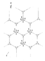
- Fig. 6 is a schematic top view of a wireless mesh network 100, in accordance with another embodiment of the present invention.
- Each node 102 in network 100 is connected to other nodes by wireless links, using respective antennas 104, 106 and 108.
- some or all of the nodes may have greater or smaller numbers of antennas and corresponding links.
- all the antennas in network 100 may transmit signals on the same frequency band or, alternatively, on two or four frequency bands if FDD is employed.
Landscapes
- Engineering & Computer Science (AREA)
- Computer Networks & Wireless Communication (AREA)
- Signal Processing (AREA)
- Physics & Mathematics (AREA)
- Mathematical Physics (AREA)
- Radio Transmission System (AREA)
- Mobile Radio Communication Systems (AREA)
Applications Claiming Priority (2)
| Application Number | Priority Date | Filing Date | Title |
|---|---|---|---|
| IL15445903 | 2003-02-13 | ||
| IL15445903A IL154459A0 (en) | 2003-02-13 | 2003-02-13 | Wireless network with intensive frequency reuse |
Publications (2)
| Publication Number | Publication Date |
|---|---|
| EP1448006A2 true EP1448006A2 (de) | 2004-08-18 |
| EP1448006A3 EP1448006A3 (de) | 2006-06-07 |
Family
ID=30012010
Family Applications (1)
| Application Number | Title | Priority Date | Filing Date |
|---|---|---|---|
| EP04075437A Withdrawn EP1448006A3 (de) | 2003-02-13 | 2004-02-12 | Drahtloses Netz mit intensiver Frequenzwiederholung |
Country Status (3)
| Country | Link |
|---|---|
| US (1) | US20040259556A1 (de) |
| EP (1) | EP1448006A3 (de) |
| IL (1) | IL154459A0 (de) |
Cited By (2)
| Publication number | Priority date | Publication date | Assignee | Title |
|---|---|---|---|---|
| EP1710960A2 (de) | 2005-04-08 | 2006-10-11 | Fujitsu Limited | Ein neues Schema zum Betreiben einer drahtlosen Station mit gerichteten Antennen |
| EP1997329A4 (de) * | 2006-03-15 | 2012-11-14 | Motorola Mobility Llc | Dynamische drahtlose backhaul-konfiguration |
Families Citing this family (35)
| Publication number | Priority date | Publication date | Assignee | Title |
|---|---|---|---|---|
| US7532901B1 (en) * | 2001-03-16 | 2009-05-12 | Radeum, Inc. | Methods and apparatus to detect location and orientation in an inductive system |
| US7965693B2 (en) * | 2002-05-28 | 2011-06-21 | Zte (Usa) Inc. | Interworking mechanism between wireless wide area network and wireless local area network |
| US7453837B2 (en) | 2002-08-15 | 2008-11-18 | Zteit Usa, Inc. | Trunking system for CDMA wireless communication |
| US7474895B1 (en) * | 2004-03-04 | 2009-01-06 | Zte (Usa) Inc. | Frequency reuse in wireless communication networks |
| CA2563696A1 (en) * | 2004-04-19 | 2005-10-27 | Zteit Usa, Inc. | Trunking and push-to-talk mechanisms for wcdma wireless communications |
| US7729303B2 (en) * | 2004-06-30 | 2010-06-01 | Zteit Usa, Inc. | Global open trunking system for CDMA wireless communication |
| KR100585152B1 (ko) * | 2004-08-02 | 2006-05-30 | 삼성전자주식회사 | 송신 타임 도메인 이퀄라이저를 사용하는 무선 ofdm기반의 모뎀 및 데이터 전송 방법 |
| US8503328B2 (en) * | 2004-09-01 | 2013-08-06 | Qualcomm Incorporated | Methods and apparatus for transmission of configuration information in a wireless communication network |
| US7415278B2 (en) * | 2004-10-27 | 2008-08-19 | Azalea Networks | Method and system for creating and deploying a mesh network |
| US7486967B2 (en) | 2005-04-13 | 2009-02-03 | Lemko Corporation | System, method, and device for providing communications using a distributed mobile architecture |
| US7548763B2 (en) * | 2005-04-13 | 2009-06-16 | Lemko Corporation | System, method, and device for providing communications using a distributed mobile architecture |
| US7539158B2 (en) | 2004-11-08 | 2009-05-26 | Lemko Corporation | System, method and device for providing communications using a distributed mobile architecture |
| US7610025B2 (en) * | 2005-03-29 | 2009-10-27 | Qualcomm Incorporated | Antenna array pattern distortion mitigation |
| US7349362B2 (en) * | 2005-06-29 | 2008-03-25 | Meshnetworks, Inc. | Method and system for implementing the time division multiple access method to AD-HOC multihopping wireless networks |
| US9204428B2 (en) * | 2005-10-26 | 2015-12-01 | Qualcomm Incorporated | Interference management using resource utilization masks sent at constant PSD |
| US8942161B2 (en) * | 2005-10-26 | 2015-01-27 | Qualcomm Incorporated | Weighted fair sharing of a wireless channel using resource utilization masks |
| US20070115817A1 (en) * | 2005-10-26 | 2007-05-24 | Qualcomm Incorporated | Minimum rate guarantees on wireless channel using resource utilization messages |
| US8918114B2 (en) * | 2005-10-26 | 2014-12-23 | Qualcomm Incorporated | Using resource utilization messages in a multi-carrier MAC to achieve fairness |
| US7949344B1 (en) * | 2006-02-13 | 2011-05-24 | Wireless Strategies, Inc. | Uncoordinated microwave paths in coordinated frequency bands |
| US7856233B2 (en) | 2006-03-30 | 2010-12-21 | Lemko Corporation | System, method, and device for providing communications using a distributed mobile architecture |
| US8224322B2 (en) | 2006-06-12 | 2012-07-17 | Lemko Corporation | Roaming mobile subscriber registration in a distributed mobile architecture |
| US8676197B2 (en) | 2006-12-13 | 2014-03-18 | Lemko Corporation | System, method, and device to control wireless communications |
| US8078109B1 (en) * | 2007-04-13 | 2011-12-13 | Wireless Stategies, Inc. | Concurrently coordinated microwave paths in coordinated frequency bands |
| US7756519B2 (en) * | 2007-05-06 | 2010-07-13 | Designart Networks Ltd | Interference mitigation technique |
| US20090175324A1 (en) * | 2008-01-04 | 2009-07-09 | Qualcomm Incorporated | Dynamic interference control in a wireless communication network |
| US8046420B2 (en) | 2008-04-23 | 2011-10-25 | Lemko Corporation | System and method to control wireless communications |
| US8340667B2 (en) | 2008-06-26 | 2012-12-25 | Lemko Corporation | System and method to control wireless communications |
| US8706105B2 (en) | 2008-06-27 | 2014-04-22 | Lemko Corporation | Fault tolerant distributed mobile architecture |
| US8107409B2 (en) | 2008-07-11 | 2012-01-31 | Lemko Corporation | OAMP for distributed mobile architecture |
| US7855988B2 (en) | 2008-07-14 | 2010-12-21 | Lemko Corporation | System, method, and device for routing calls using a distributed mobile architecture |
| US7979066B2 (en) | 2008-09-25 | 2011-07-12 | Lemko Corporation | Multiple IMSI connections |
| JP5446671B2 (ja) * | 2009-09-29 | 2014-03-19 | ソニー株式会社 | 無線伝送システム及び無線通信方法 |
| JP5693299B2 (ja) * | 2011-03-03 | 2015-04-01 | キヤノン株式会社 | 通信装置およびその制御方法、並びにプログラム |
| US9509466B2 (en) | 2012-04-27 | 2016-11-29 | Hewlett Packard Enterprise Development Lp | Overlapping sub-channels in a network |
| CA2875701C (en) | 2012-06-21 | 2016-08-23 | Cable Television Laboratories, Inc. | Efficient adaptable wireless network system with agile beamforming |
Family Cites Families (18)
| Publication number | Priority date | Publication date | Assignee | Title |
|---|---|---|---|---|
| JPS59101906A (ja) * | 1982-12-02 | 1984-06-12 | Mitsubishi Electric Corp | アンテナ装置 |
| DE69327837T2 (de) * | 1992-12-01 | 2000-10-12 | Koninklijke Philips Electronics N.V., Eindhoven | Teilband-Diversityübertragungssystem |
| US5634199A (en) * | 1993-04-14 | 1997-05-27 | Stanford University | Method of subspace beamforming using adaptive transmitting antennas with feedback |
| US5471647A (en) * | 1993-04-14 | 1995-11-28 | The Leland Stanford Junior University | Method for minimizing cross-talk in adaptive transmission antennas |
| IL112233A (en) * | 1995-01-03 | 1998-02-22 | State Rafaelel Ministry Of Def | Adaptive polarization diversity system |
| US6035266A (en) * | 1997-04-16 | 2000-03-07 | A.L. Air Data, Inc. | Lamp monitoring and control system and method |
| US6008760A (en) * | 1997-05-23 | 1999-12-28 | Genghis Comm | Cancellation system for frequency reuse in microwave communications |
| US6058105A (en) * | 1997-09-26 | 2000-05-02 | Lucent Technologies Inc. | Multiple antenna communication system and method thereof |
| US5982327A (en) * | 1998-01-12 | 1999-11-09 | Motorola, Inc. | Adaptive array method, device, base station and subscriber unit |
| US6289004B1 (en) * | 1998-03-12 | 2001-09-11 | Interdigital Technology Corporation | Adaptive cancellation of fixed interferers |
| US6141393A (en) * | 1999-03-03 | 2000-10-31 | Motorola, Inc. | Method and device for channel estimation, equalization, and interference suppression |
| US6426973B1 (en) * | 1999-04-29 | 2002-07-30 | The Board Of Trustees Of The University Of Illinois | Differential minimum mean squared error communication signal compensation method |
| US6285861B1 (en) * | 1999-06-14 | 2001-09-04 | Qualcomm Incorporated | Receiving station with interference signal suppression |
| US6377636B1 (en) * | 1999-11-02 | 2002-04-23 | Iospan Wirless, Inc. | Method and wireless communications system using coordinated transmission and training for interference mitigation |
| US6473467B1 (en) * | 2000-03-22 | 2002-10-29 | Qualcomm Incorporated | Method and apparatus for measuring reporting channel state information in a high efficiency, high performance communications system |
| US6980806B2 (en) * | 2000-03-22 | 2005-12-27 | Hitachi Kokusai Electric Inc. | Radio system |
| US6377819B1 (en) * | 2000-04-06 | 2002-04-23 | Iospan Wireless, Inc. | Wireless communication system using joined transmit and receive processing |
| EP2521285B1 (de) * | 2001-09-12 | 2014-02-26 | Intel Mobile Communications GmbH | Drahtlose CDMA-Systeme |
-
2003
- 2003-02-13 IL IL15445903A patent/IL154459A0/xx unknown
-
2004
- 2004-02-11 US US10/777,281 patent/US20040259556A1/en not_active Abandoned
- 2004-02-12 EP EP04075437A patent/EP1448006A3/de not_active Withdrawn
Cited By (4)
| Publication number | Priority date | Publication date | Assignee | Title |
|---|---|---|---|---|
| EP1710960A2 (de) | 2005-04-08 | 2006-10-11 | Fujitsu Limited | Ein neues Schema zum Betreiben einer drahtlosen Station mit gerichteten Antennen |
| EP1710960A3 (de) * | 2005-04-08 | 2006-11-15 | Fujitsu Limited | Ein neues Schema zum Betreiben einer drahtlosen Station mit gerichteten Antennen |
| US7630343B2 (en) | 2005-04-08 | 2009-12-08 | Fujitsu Limited | Scheme for operating a wireless station having directional antennas |
| EP1997329A4 (de) * | 2006-03-15 | 2012-11-14 | Motorola Mobility Llc | Dynamische drahtlose backhaul-konfiguration |
Also Published As
| Publication number | Publication date |
|---|---|
| US20040259556A1 (en) | 2004-12-23 |
| IL154459A0 (en) | 2003-09-17 |
| EP1448006A3 (de) | 2006-06-07 |
Similar Documents
| Publication | Publication Date | Title |
|---|---|---|
| EP1448006A2 (de) | Drahtloses Netz mit intensiver Frequenzwiederholung | |
| JP4316496B2 (ja) | 位相および振幅較正を伴った多チャンネル無線送信器および受信器のための方法およびシステム | |
| KR102367370B1 (ko) | 정규 직교 시간-주파수 시프팅 통신 시스템에서 변조 및 등화 | |
| US7075967B2 (en) | Wireless communication system using block filtering and fast equalization-demodulation and method of operation | |
| US6243412B1 (en) | Adaptive array transmitter receiver | |
| US6483866B1 (en) | Multi-station transmission method and receiver for inverse transforming two pseudo-orthogonal transmission sequences used for metric calculation and base station selection based thereon | |
| US9014149B2 (en) | Communication apparatus and base station apparatus | |
| US8254509B2 (en) | Receiver | |
| EP2920897B1 (de) | Verfahren und vorrichtung zur gruppenantennenkalibrierung mit verkehrssignalen | |
| US20140370823A1 (en) | Methods, processing device, computer programs, computer program products, and antenna apparatus for calibration of antenna apparatus | |
| US6445342B1 (en) | Method and device for multi-user frequency-domain channel estimation | |
| EP0993707A2 (de) | Interpretation eines empfangsignals | |
| US8705649B2 (en) | Method and receiver structure for interference cancellation in co-ordinated multipoint systems | |
| EP3704820B1 (de) | Orthogonale trainingssignale zur übertragung in einem antennenarray | |
| US9729220B1 (en) | Transmit diversity and receive diversity for single carrier modulation | |
| WO1999034532A2 (en) | Upgrading of resources in a telecommunications network | |
| US8139544B1 (en) | Pilot tone processing systems and methods | |
| EP1336261B1 (de) | Auf determinanten basierende synchronisationstechniken und -systeme | |
| US10972193B2 (en) | Method and apparatus for antenna array calibration with interference reduction | |
| KR100425611B1 (ko) | 통신 단말 장치, 기지국 장치 및 적응 등화 처리 방법 | |
| EP4500709A1 (de) | Los-mimo-mikrowellenfunkverbindungsrekonfiguration für eine variable anzahl von mimo-datenströmen | |
| EP4500702A1 (de) | Los-mimo-mikrowellenfunkverbindungskanalschätzung für rangdefiziente kanäle | |
| JP7648944B2 (ja) | 受信機及び受信方法 | |
| JP2025122325A (ja) | 無線通信システム | |
| CN110661736B (zh) | 信号处理方法及相关装置 |
Legal Events
| Date | Code | Title | Description |
|---|---|---|---|
| PUAI | Public reference made under article 153(3) epc to a published international application that has entered the european phase |
Free format text: ORIGINAL CODE: 0009012 |
|
| AK | Designated contracting states |
Kind code of ref document: A2 Designated state(s): AT BE BG CH CY CZ DE DK EE ES FI FR GB GR HU IE IT LI LU MC NL PT RO SE SI SK TR |
|
| AX | Request for extension of the european patent |
Extension state: AL LT LV MK |
|
| PUAL | Search report despatched |
Free format text: ORIGINAL CODE: 0009013 |
|
| AK | Designated contracting states |
Kind code of ref document: A3 Designated state(s): AT BE BG CH CY CZ DE DK EE ES FI FR GB GR HU IE IT LI LU MC NL PT RO SE SI SK TR |
|
| AX | Request for extension of the european patent |
Extension state: AL LT LV MK |
|
| RIC1 | Information provided on ipc code assigned before grant |
Ipc: H04B 7/08 20060101ALI20060420BHEP Ipc: H04Q 7/36 20060101AFI20040601BHEP |
|
| AKX | Designation fees paid | ||
| REG | Reference to a national code |
Ref country code: DE Ref legal event code: 8566 |
|
| STAA | Information on the status of an ep patent application or granted ep patent |
Free format text: STATUS: THE APPLICATION IS DEEMED TO BE WITHDRAWN |
|
| 18D | Application deemed to be withdrawn |
Effective date: 20061208 |