EP1447879A1 - Ein Verlängerungsstück für eine Antennengrundplatte, eine Antennengrundplatte, eine Antenne und dieselbe verwendende Vorrichtungen - Google Patents
Ein Verlängerungsstück für eine Antennengrundplatte, eine Antennengrundplatte, eine Antenne und dieselbe verwendende Vorrichtungen Download PDFInfo
- Publication number
- EP1447879A1 EP1447879A1 EP03003440A EP03003440A EP1447879A1 EP 1447879 A1 EP1447879 A1 EP 1447879A1 EP 03003440 A EP03003440 A EP 03003440A EP 03003440 A EP03003440 A EP 03003440A EP 1447879 A1 EP1447879 A1 EP 1447879A1
- Authority
- EP
- European Patent Office
- Prior art keywords
- ground plate
- extension
- antenna
- antenna element
- mobile device
- Prior art date
- Legal status (The legal status is an assumption and is not a legal conclusion. Google has not performed a legal analysis and makes no representation as to the accuracy of the status listed.)
- Withdrawn
Links
Images


Classifications
-
- H—ELECTRICITY
- H01—ELECTRIC ELEMENTS
- H01Q—ANTENNAS, i.e. RADIO AERIALS
- H01Q1/00—Details of, or arrangements associated with, antennas
- H01Q1/48—Earthing means; Earth screens; Counterpoises
-
- H—ELECTRICITY
- H01—ELECTRIC ELEMENTS
- H01Q—ANTENNAS, i.e. RADIO AERIALS
- H01Q1/00—Details of, or arrangements associated with, antennas
- H01Q1/12—Supports; Mounting means
- H01Q1/22—Supports; Mounting means by structural association with other equipment or articles
- H01Q1/24—Supports; Mounting means by structural association with other equipment or articles with receiving set
- H01Q1/241—Supports; Mounting means by structural association with other equipment or articles with receiving set used in mobile communications, e.g. GSM
- H01Q1/242—Supports; Mounting means by structural association with other equipment or articles with receiving set used in mobile communications, e.g. GSM specially adapted for hand-held use
- H01Q1/243—Supports; Mounting means by structural association with other equipment or articles with receiving set used in mobile communications, e.g. GSM specially adapted for hand-held use with built-in antennas
-
- H—ELECTRICITY
- H01—ELECTRIC ELEMENTS
- H01Q—ANTENNAS, i.e. RADIO AERIALS
- H01Q1/00—Details of, or arrangements associated with, antennas
- H01Q1/44—Details of, or arrangements associated with, antennas using equipment having another main function to serve additionally as an antenna, e.g. means for giving an antenna an aesthetic aspect
Definitions
- the invention relates to construction of antennas and, more specifically, to extending of a ground plate for an antenna.
- the antenna In order to communicate with other devices or with any communications infrastructure, such as a mobile network, the antenna need have operating characteristics meeting strict requirements, such as those relating to resonant frequency, bandwidth, and gain.
- the most traditional 900 MHz frequency band extends from 880 to 960 MHz.
- the frequency range is even larger, extending from 886 to 931 MHz.
- Most network operators have taken some other frequency bands in use so that most state-of-the-art devices are now supposed to have at least dual band characteristics, the second band being commonly around 1800 MHz.
- Figure 1 shows an example of a modern structure for an internal antenna 100, such as the Folded Inverted-F Antenna FIFA or the microstrip patch antenna.
- an internal antenna 100 such as the Folded Inverted-F Antenna FIFA or the microstrip patch antenna.
- Such a structure is very suitable for relatively small mobile devices. These structures are used in most mobile phones available on the market at the time of writing. They provide many benefits simply by being small, lightweight, efficient, and relatively flat. Further, they apt well for mass production because they can be implemented as printed circuit antennas.
- the shape of the copper strip defines the resonance frequencies. Such a copper strip as schematically illustrated in Figure 1 has two resonances on 900 MHz and 1800 MHz.
- the antenna element (i.e. transducer) 101 of a FIFA or microstrip patch antenna has a size very small compared to the wavelength.
- the conductor strip as antenna element 101 is attached by connector 107 (which is also a short point) to the ground plate 103, such as to a printed circuit board PCB.
- the feed line 105 brings the actual signal to be transmitted to the antenna element 101.
- the antenna element 101 has a very high-Q value meaning that the resulting bandwidth is extremely narrow. In order to cope with the requirements defined in different communications standards, the bandwidth must be broader.
- Figure 2 shows a known principle how this can be done, as geniously disclosed by several authors, such as by Vainikainen et al. in "Effect of Phone Chassis on Handset Antenna Performance" (Report S240, HUT Radio Laboratory Publications, Espoo, March 2000), by coupling the antenna element to a ground plate.
- the antenna element 101 of Figure 1 is now the first monopole 201 of a dipole antenna 200, whereas the ground plate 103 works as the other monopole 203 of the same dipole antenna 200.
- the ground plate 103 is very big compared to the wavelength and has then a low-Q value, so that the resulting combination antenna 100 has a larger bandwidth.
- the size of a mobile device wherein the antenna should be used is getting very small. This is going to lead to further challenges in the field of antenna design, because, in response to a very small size of the ground plate, the bandwidth requirements cannot be met any more for the lower frequencies, such as for the 900 MHz band.
- EP 0 288 676 has a loop antenna; the problems related to loop antennas are different from the antennas regularly used for GSM frequencies.
- the antenna being the coupling element, is housed inside the strap.
- US 6,366,250 discloses a conductive shielding in a wrist strap for a sort of dipole antenna.
- the purpose of the shielding is to shield the user from the electrical field generated by the antenna. This is done in order to improve reception by minimizing the relative load of the wrist of the user; otherwise this load would reduce the sensitivity of the antenna.
- the shieldings may however disturb the antenna performance significantly.
- WO 2001/91229 has a much similar shielding.
- the wristwatch device of US 6,212,414 has all device transmitter and receiver electronics in the wrist strap. Therefore, the candidate user will be mesmerized by its size. Further, the performance of spring-retractable antenna system of '414 may be questionable.
- the ground plate is the ground plate for an antenna element, such as a FIFA or a microstrip antenna element.
- an antenna element such as a FIFA or a microstrip antenna element.
- the antenna element can be designed to be used for at least one mobile communications frequency band, thus allowing a dual- or multi-band capabilities. Then the extension is designed to improve the performance of the antenna on at least one of said frequency bands.
- the electrical length of the extension together with the ground plate can be optimized to produce a reflection coefficient close or at a minimum reflection coefficient for a predefined frequency band, especially for the GSM 900 MHz or the GSM 850 band (which is widely used in the US, 824 MHz to 894 MHz). This enables the use of a very small chassis providing too small a ground plate for the antenna element selected.
- the extension can further include connecting means adapted to connect said extension for a ground plate to said ground plate. This makes the assembling step more easy. Further, if performed by an end-user, the user can conveniently join the extension to the ground plate.
- the extension may further comprise releasing means, such as a release switch, adapted to detach said extension from said ground plate. This allows the user to change the physical size of his/her mobile device, and whenever necessary, plug in the extension for better radio coverage etc. on the band for which the extension has been designed.
- releasing means such as a release switch
- the extension can be within, on, and/or around carrying means, such as a neck strap or wrist strap. This is very practical, because then the user does not need to remember the extension but it is automatically carried with.
- the extension can comprise power supply means, such as a rechargeable battery. Especially when a Lithium-Ion-battery is used as the rechargeable battery, the rechargeable battery itself can work as the extension. This is very favourable because there is then no need for an extra component.
- the extension can be within or connected to a desktop stand.
- An advantage of such a solution is that it cures the degradation of the radio capabilities caused by removing a previous extension if the previous extension is normally located in such a part that has to be removed before the device is placed to the desktop stand.
- the extension can be within or connected to any accessory for the mobile terminal.
- the desktop stand further includes an isolator circuitry between a charger and the desktop stand.
- Said isolator circuitry can comprise at least two coils, for example.
- a ground plate is to be used together with an extension.
- the ground plate is preferably without the extension shorter than a wavelength of one of the bands for which the antenna element coupling with the ground plate is designed. In this manner, the size of the ground plate can be reduced thus enabling the further miniaturization of the mobile terminal and giving better radio capabilities also for radio bands with frequencies having a longer wavelength than the dimensions of the ground plate.
- the invention as described is especially suitable for small-sized mobile devices, such as pendant phones and/or wrist phones.
- Figure 3 shows results of simulations of the effect the length of the ground plate of an antenna on the bandwidth obtained.
- the high-Q coupling element 101 is fixed, and the electrical length L of the gound plate 103 is changed.
- the coupling element 101 corresponds to such typically used for GSM 900 band, and can be as shown in Figure 1, where the coupling element 101 is in itself a low-Q coupling element for also GSM 1800 band.
- the bandwidth BW is at maximum BW max when the electrical length L of the ground plate 103 is about 14 cm.
- the bandwidth BW is relatively close to the maximum BW max also when the electrical length L of the the ground plate 103 is within a lenght range [14 cm - ⁇ L - , 14 cm + ⁇ L + ], where ⁇ L - and ⁇ L + are both some millimeters.
- the optimal length L of the ground plate is a bit shorter due to the effect of the dielectric housing of a mobile device wherein the antenna is used. The exact magnitude of this effect depends on the dielectric, so usually a length L around 13 cm is optimal, so the ⁇ L + is shorter than ⁇ L-.
- the range from 130 to 145 mm would be the optimal range for the length L of ground plate 103, giving 90 MHz Bandwidth.
- the acceptable range for the length of the ground plate 103 would be from a bit more than 120 mm to around 150 mm.
- Figure 4 shows one of the ideas behind the invention: the main problem with the poor performance of the antenna of a mobile terminal 400 lies in the fact that the electrical length L' of the ground plate 403 would now be too small. In the new Siemens K2, for example, the printed circuit board is around 6 cm; as seen from Figure 3, the resulting bandwidth would then be relatively small. Therefore, an extension 405 for the ground plate 405 is required.
- the extension 405 connected by using connecting part 407 acts together with the ground plate 403 as a bigger ground plate for the antenna element 101, which like in Figure 1 is connected by using a connector 107 to the ground plate and fed at the feed line 105.
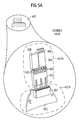
- Figure 5A shows a zoomed view of the connecting part 407.
- the ground plate say the PCB
- terminal side connecting means 407A which are matched to fit together with extension side connecting means 407B.
- the terminal side connecting means 407A comprise only a connector socket 501.
- the connector socket 501 is electrically connected to the ground plate 403.
- the extension side connecting means 407B comprise at least a connector 503.
- the connector 503 is elecrically connected to the extension 405 of the ground plate 403.
- the extension 405 is preferably covered by cover 504.
- the extension side may optionally comprise also communication wires 505 which are through connector 503 and connector socket 501 connected to corresponding circuitry on the PCB in practice on another layer of the PCB than the ground plate 403.
- the communication wires 505 may also be covered by cover 506.
- a possible purpose of the communication wires 505 is to enable a hands-free use of the terminal 400, and therefore they may be further connected to a headset including a loudspeaker (bone conductor, for example) and microphone.
- Figure 5B illustrates the extension side connecting means 407B in more detail.
- the extension 405 is implemented using wires 405 that are fixed to the connector 503.
- the extension 405 continues then inside the strap under cover 504 and may be implemented using wires, or a plate- or strip-like structure.
- the communication wires 505 run on other side of the connector 503.
- the isolation between the communication wires 505 and the extension 405 can be enhanced because, as already noted, the ground plate 403 is conventionally. in a different layer of the PCB as the circuitry.
- the release switch 509 such as a press-button can be used to detach the extension side 407B from the terminal side 407A.
- Figure 5C shows the extension side 407B from another angle.
- the release switch 509 which is operationally connected to lock pin 513.
- the lock pin 513 locks the extension side 407B to the terminal side 407A.
- the guide pin 511 is intended for helping the user to attach the extension side 407B in a right manner to the terminal side 407A.
- Figure 6 shows a use case of one embodiment of the present invention.
- the mobile terminal 400 is carried on carrying means 600 comprising a neck strap 601 and extension 405 of the ground plate 403.
- the extension 405 may be hidden inside the neck strap 601 as well. The user is very satisfied because despite of the extremely small size of the mobile terminal the performance of the radio part is excellent because of the extension 405 of the ground plate.
- Communication wires 505 are inside the neck strap 601 in the other branch of the neck strap 601 than the extension 405 in order to reduce distortions. Otherwise it could be very hard to decouple the communication wires 505 from the extension 405.
- Figure 7 shows one further embodiment of the present invention applied to a device carried on or around user's wrist.
- the electronics is included in the mobile terminal 400; the extension 405 of the ground plate 403 is again hidden inside the carrying means 600.
- FIG 8 shows one further embodiment of the present invention applied to a tabletop stand.
- the table stand includes an extension 405 for the ground plate 403.
- a small-sized radio device which normally has an extension 405, for example, in the carrying means 600, loses a significant part of its bandwidth, especially on 900 MHz band, when the carrying means are removed. The reason behind this is that the electrical length L of the ground plate 403 changes then drastically. This enables a construction in which the charger connector is placed on the same opening of the housing as the extension connector socket 501. Further it enables that the carrying means 600 can be removed when the mobile terminal 400 is in a tabletop stand; this results in optically more appealing design.
- the solution for the problem is to include an extension 405 to the tabletop stand.
- the antenna element 101 could see the charger wire 802 as a longer ground plate when charger 801 is attached.
- the transformer line will disturb the extension because it is longer so that the electrical length the antenna element sees changes.
- the degradation of the antenna quality is not a problem so no filtering or isolating is necessary. It is somehow acceptable that the antenna performance degrades while the terminal is being charged. However, for a very small mobile device the length is too short to enable a proper performance. Then in some cases the performance of the extension of the ground plate can not be good enough to
- the impedance of the component is selected to be very high at the desired bandwidth of the extension. This can be done by using an isolator having filter characteristics.
- the isolator can be constructed by using selected components, especially coils, which have a resonance frequency at 900 MHz. The isolator does not allow the radio signal to pass into the charger line. A coil is ideal for isolator because it lets Direct Current almost completely and unattenuated through.
- the isolator circuitry 805 works also in the other direction so that the mobile terminal 400 does not cause disturbances in the mains network when the mains plug 803 is connected.
- Figure 9 shows a possible structure of the inventive isolator circuitry 805.
- the isolator circuitry 805 includes preferably two isolating circuits 901A, 901B which isolate leads 904A, B to charger 801 from leads 903A, B to mobile terminal 400 or desktop stand 800, respectively.
- the isolator can include also special ferrites instead or in addition to the coils. This is practical for lower frequencies of some hundrer MHz.
- the ferrite ring is placed in a known manner around the power line, but this time between the desktop stand and the charger, or in the charger wire.
- Each of the isolator circuits 901A, 901B includes preferably a coil 905.
- a coil 905 usually has some capacitance which is the reason that the isolator circuit 901B shows also a parallel capacitor 907.
- FIG 10A and B show one principle according to which the coil 905 in the isolating circuit 901A, 901B of Figure 9 can be selected.
- the coil 905 introduces a high impedance with a complex phase that decreases with growing frequency f.
- the impedance changes from being almost purely inductive at lower frequencies to almost purely capacitive at higher frequencies.
- the impedance is at its maximum and pure resistive. Beyond this resonance frequency f 0 the capacitor is dominating, and so on.
- Figure 10B shows that the impedance
- the mobile terminal 400 includes only at least the coupling point as the connector socket 501 and the antenna element 101.
- the feeding of the antenna is then done in the mobile device, close to or on the PCB.
- the ground plate 403 is then located at the socket 501 and the rest of the ground plate is located in the extension 405 of the ground plate 403.
- the antenna element 101 can be any type of antenna element also other than FIFA, such as a PIFA, loop antenna, or any patch antenna.
Priority Applications (1)
| Application Number | Priority Date | Filing Date | Title |
|---|---|---|---|
| EP03003440A EP1447879A1 (de) | 2003-02-14 | 2003-02-14 | Ein Verlängerungsstück für eine Antennengrundplatte, eine Antennengrundplatte, eine Antenne und dieselbe verwendende Vorrichtungen |
Applications Claiming Priority (1)
| Application Number | Priority Date | Filing Date | Title |
|---|---|---|---|
| EP03003440A EP1447879A1 (de) | 2003-02-14 | 2003-02-14 | Ein Verlängerungsstück für eine Antennengrundplatte, eine Antennengrundplatte, eine Antenne und dieselbe verwendende Vorrichtungen |
Publications (1)
| Publication Number | Publication Date |
|---|---|
| EP1447879A1 true EP1447879A1 (de) | 2004-08-18 |
Family
ID=32668983
Family Applications (1)
| Application Number | Title | Priority Date | Filing Date |
|---|---|---|---|
| EP03003440A Withdrawn EP1447879A1 (de) | 2003-02-14 | 2003-02-14 | Ein Verlängerungsstück für eine Antennengrundplatte, eine Antennengrundplatte, eine Antenne und dieselbe verwendende Vorrichtungen |
Country Status (1)
| Country | Link |
|---|---|
| EP (1) | EP1447879A1 (de) |
Cited By (6)
| Publication number | Priority date | Publication date | Assignee | Title |
|---|---|---|---|---|
| US7782269B2 (en) | 2004-11-12 | 2010-08-24 | Fractus, S.A. | Antenna structure for a wireless device with a ground plane shaped as a loop |
| US7903034B2 (en) | 2005-09-19 | 2011-03-08 | Fractus, S.A. | Antenna set, portable wireless device, and use of a conductive element for tuning the ground-plane of the antenna set |
| WO2012156872A1 (en) * | 2011-05-17 | 2012-11-22 | Koninklijke Philips Electronics N.V. | Neck cord incorporating earth plane extensions |
| GB2494922A (en) * | 2011-09-26 | 2013-03-27 | Antenova Ltd | External and flexible groundplane extensions for antennas |
| CN106558758A (zh) * | 2016-11-28 | 2017-04-05 | 深圳众思科技有限公司 | 可穿戴设备 |
| CN106711585A (zh) * | 2017-01-11 | 2017-05-24 | 深圳市天威讯无线技术有限公司 | 一种智能手表天线结构 |
Citations (5)
| Publication number | Priority date | Publication date | Assignee | Title |
|---|---|---|---|---|
| EP1111713A1 (de) * | 1999-12-23 | 2001-06-27 | Alcatel | Mobiltelefon mit einer Antenne und einer Grundplatte |
| US6366250B1 (en) * | 1999-12-09 | 2002-04-02 | Sirf Technology, Inc. | Wrist mounted wireless instrument and antenna apparatus |
| US6456249B1 (en) * | 1999-08-16 | 2002-09-24 | Tyco Electronics Logistics A.G. | Single or dual band parasitic antenna assembly |
| US6466176B1 (en) * | 2000-07-11 | 2002-10-15 | In4Tel Ltd. | Internal antennas for mobile communication devices |
| EP1257001A1 (de) * | 2001-05-12 | 2002-11-13 | TELEFONAKTIEBOLAGET LM ERICSSON (publ) | Schnittstelle zwischen Mobilfunkgerät und Zubehörgerät basierend auf kapazitiver Kopplung zur gemeinsamen Nutzung der Masseflächen um den Antennengewinn des Zubehörgeräts zu erhöhen |
-
2003
- 2003-02-14 EP EP03003440A patent/EP1447879A1/de not_active Withdrawn
Patent Citations (5)
| Publication number | Priority date | Publication date | Assignee | Title |
|---|---|---|---|---|
| US6456249B1 (en) * | 1999-08-16 | 2002-09-24 | Tyco Electronics Logistics A.G. | Single or dual band parasitic antenna assembly |
| US6366250B1 (en) * | 1999-12-09 | 2002-04-02 | Sirf Technology, Inc. | Wrist mounted wireless instrument and antenna apparatus |
| EP1111713A1 (de) * | 1999-12-23 | 2001-06-27 | Alcatel | Mobiltelefon mit einer Antenne und einer Grundplatte |
| US6466176B1 (en) * | 2000-07-11 | 2002-10-15 | In4Tel Ltd. | Internal antennas for mobile communication devices |
| EP1257001A1 (de) * | 2001-05-12 | 2002-11-13 | TELEFONAKTIEBOLAGET LM ERICSSON (publ) | Schnittstelle zwischen Mobilfunkgerät und Zubehörgerät basierend auf kapazitiver Kopplung zur gemeinsamen Nutzung der Masseflächen um den Antennengewinn des Zubehörgeräts zu erhöhen |
Non-Patent Citations (1)
| Title |
|---|
| VAINIKAINEN P ET AL: "RESONATOR-BASED ANALYSIS OF THE COMBINATION OF MOBILE HANDSET ANTENNA AND CHASSIS", IEEE TRANSACTIONS ON ANTENNAS AND PROPAGATION, IEEE INC. NEW YORK, US, vol. 50, no. 10, October 2002 (2002-10-01), pages 1433 - 1444, XP001141168, ISSN: 0018-926X * |
Cited By (16)
| Publication number | Priority date | Publication date | Assignee | Title |
|---|---|---|---|---|
| US7782269B2 (en) | 2004-11-12 | 2010-08-24 | Fractus, S.A. | Antenna structure for a wireless device with a ground plane shaped as a loop |
| US8077110B2 (en) | 2004-11-12 | 2011-12-13 | Fractus, S.A. | Antenna structure for a wireless device with a ground plane shaped as a loop |
| US11276922B2 (en) | 2004-11-12 | 2022-03-15 | Fractus, S.A. | Antenna structure for a wireless device |
| US9054418B2 (en) | 2004-11-12 | 2015-06-09 | Fractus, S.A. | Antenna structure for a wireless device with a ground plane shaped as a loop |
| US8493280B2 (en) | 2004-11-12 | 2013-07-23 | Fractus, S.A. | Antenna structure for a wireless device with a ground plane shaped as a loop |
| US7903034B2 (en) | 2005-09-19 | 2011-03-08 | Fractus, S.A. | Antenna set, portable wireless device, and use of a conductive element for tuning the ground-plane of the antenna set |
| US8138981B2 (en) | 2005-09-19 | 2012-03-20 | Fractus, S.A. | Antenna set, portable wireless device, and use of a conductive element for tuning the ground-plane of the antenna set |
| JP2014517605A (ja) * | 2011-05-17 | 2014-07-17 | コーニンクレッカ フィリップス エヌ ヴェ | 接地面伸長部を組み込んだ首紐 |
| CN103534872A (zh) * | 2011-05-17 | 2014-01-22 | 皇家飞利浦有限公司 | 合并接地平面延伸部的颈部绳 |
| US9178556B2 (en) | 2011-05-17 | 2015-11-03 | Koninklijke Philips N.V. | Neck cord incorporating earth plane extensions |
| CN103534872B (zh) * | 2011-05-17 | 2016-05-18 | 皇家飞利浦有限公司 | 合并接地平面延伸部的颈部绳 |
| WO2012156872A1 (en) * | 2011-05-17 | 2012-11-22 | Koninklijke Philips Electronics N.V. | Neck cord incorporating earth plane extensions |
| GB2494922A (en) * | 2011-09-26 | 2013-03-27 | Antenova Ltd | External and flexible groundplane extensions for antennas |
| CN106558758A (zh) * | 2016-11-28 | 2017-04-05 | 深圳众思科技有限公司 | 可穿戴设备 |
| CN106711585A (zh) * | 2017-01-11 | 2017-05-24 | 深圳市天威讯无线技术有限公司 | 一种智能手表天线结构 |
| CN106711585B (zh) * | 2017-01-11 | 2023-12-01 | 深圳市天威讯无线技术有限公司 | 一种智能手表天线结构 |
Similar Documents
| Publication | Publication Date | Title |
|---|---|---|
| CN113013593B (zh) | 天线组件和电子设备 | |
| WO2022068827A1 (zh) | 天线组件和电子设备 | |
| EP1706917B1 (de) | Mehrband-antennensystem | |
| JP4242780B2 (ja) | 平衡マルチバンドアンテナ装置 | |
| US7069043B2 (en) | Wireless communication device with two internal antennas | |
| US7760146B2 (en) | Internal digital TV antennas for hand-held telecommunications device | |
| US7199762B2 (en) | Wireless device with distributed load | |
| JP2016027715A (ja) | アンテナ装置および電子機器 | |
| US7559803B2 (en) | Connection structure and signal transmission cable | |
| EP2219265A1 (de) | Antennenvorrichtung, Antennensystem und tragbare Funkkommunikationsvorrichtung mit solch einer Antennenvorrichtung | |
| KR20020027636A (ko) | 안테나 장치 및 휴대용 무선 통신 장치 | |
| EP1611637A2 (de) | Am körper zu tragendes persönliches kommunikationsgerät | |
| CN102318138A (zh) | 天线装置、印刷电路板、便携式电子设备和变换工具包 | |
| US7495619B2 (en) | Systems and methods that utilize an active stub/parasitic whip antenna to facilitate mobile communication | |
| CN103262428B (zh) | 用于移动通信装置的伸缩天线 | |
| JPH11163756A (ja) | 携帯無線機 | |
| CA2178382C (en) | Combined antenna apparatus and method for receiving and transmitting radio frequency signals | |
| US7801552B2 (en) | Suppression of near-field effects in mobile handsets | |
| US8174453B2 (en) | Folder-type mobile communication device | |
| EP1447879A1 (de) | Ein Verlängerungsstück für eine Antennengrundplatte, eine Antennengrundplatte, eine Antenne und dieselbe verwendende Vorrichtungen | |
| JP2008522527A (ja) | 無線電話信号を消去するように適合させた内蔵型平面テレビアンテナを有するモバイル電話 | |
| JP3033746B1 (ja) | 無線通信装置 | |
| JP2003283238A (ja) | アンテナ装置、通信装置、およびアンテナ装置設計方法 | |
| WO2000046873A1 (en) | Wireless phone design for improving radiation performance | |
| Collins | Handset antennas |
Legal Events
| Date | Code | Title | Description |
|---|---|---|---|
| PUAI | Public reference made under article 153(3) epc to a published international application that has entered the european phase |
Free format text: ORIGINAL CODE: 0009012 |
|
| 17P | Request for examination filed |
Effective date: 20031020 |
|
| AK | Designated contracting states |
Kind code of ref document: A1 Designated state(s): AT BE BG CH CY CZ DE DK EE ES FI FR GB GR HU IE IT LI LU MC NL PT SE SI SK TR |
|
| AX | Request for extension of the european patent |
Extension state: AL LT LV MK RO |
|
| STAA | Information on the status of an ep patent application or granted ep patent |
Free format text: STATUS: THE APPLICATION IS DEEMED TO BE WITHDRAWN |
|
| 18D | Application deemed to be withdrawn |
Effective date: 20040629 |