TECHNICAL FIELD
The present invention relates to a pressure
release valve provided in a sealing plate of a pressure
container in an electric or electronic part, for example,
an electric battery (including a primary battery and
a secondary battery), a fuel battery, a condenser and
the like, or a pressure container in a general machinery.
BACKGROUND ART
In a closed type aluminum electrolytic condenser
or an electric double layer type condenser or the like,
an opening portion of a pressure container receiving
an element main body thereof is closed by a sealing
plate sealed via a gasket. In the case of the complete
sealing structure as mentioned above, there is a risk
that internal pressure of the container is increased
on the basis of a Joule heat generation in the case
that a sudden load is applied, whereby reduction in
function and reduction in service life are caused.
Accordingly, there has been conventionally developed
a structure which can release a gas generated in the
container, by forming a notch in a bottom portion of
the pressure container so as to provide a rupture plate,
or mounting a rubber cap to a cover so as to provide
a safety valve, thereby preventing the pressure
container from being ruptured, or by mounting a breather
having the function of transmitting the gas and not
transmitting the liquid to a sealing plate by the way
of applying a water repelling treatment to a porous
membrane made of, for example, PTFE or the like so as
to release the internal pressure of the container.
In accordance with the prior art, in the case that
the sealing plate has the rupture plate or the safety
valve, once the container is ruptured, the sealing plate
can not be used thereafter, whereby it is impossible
to use the sealing plate repeatedly.
Further, the breather provided in the sealing
plate has a function of keeping the internal pressure
of the pressure container constant, and preventing an
internally sealed liquid such as an electrolytic
solution or the like from leaking, however, since the
gas within the container is discharged slightly from
the breather even by heat and internal pressure
generated in a normal use state, the electrolytic
solution tends to be reduced due to evaporation, and
water vapor tends to make an intrusion from the external.
Further, under a bad environment, there is a case that
the porous membrane of the breather generates clogging,
and it is hard to expect a stable performance. Further,
since the breather can not respond to a sudden internal
pressure increase, it is necessary to provide
additionally with an explosion proofing valve for
releasing the internal pressure in a moment of time
in the case that the internal pressure becomes a
predetermined value or more and preventing the
container from being exploded.
The present invention is made by taking the points
mentioned above into consideration, and a technical
object of the present invention is to provide a pressure
release valve which can securely achieve a pressure
release function repeatedly because the pressure
release valve is not broken due to a pressure release
at a time when an internal pressure is increased, in
addition to a breather function of preventing a sealed
liquid from being evaporated and preventing foreign
matter from making an intrusion from the external.
DISCLOSURE OF THE INVENTION
As a means for effectively achieving the technical
object mentioned above, in accordance with a first
aspect of the present invention, there is provided a
pressure release valve comprising:
wherein the valve body has a seal lip which is
directed to the outside of the pressure container and
is closely contacted with an outer peripheral surface
of the shaft part by predetermined tensional force.
In other words, the pressure release valve is normally
closed so as to hermetically close the inside of the
pressure container, and is structured such that in the
case that internal pressure of the pressure container
is increased more than a predetermined value, the seal
lip is operated so as to open the valve, thereby
releasing the internal pressure to the atmospheric air.
In accordance with a second aspect of the present
invention, there is provided a pressure release valve
comprising:
wherein the valve body has a seal lip which is
closely contacted with the tubular holding portion by
predetermined tensional force and is operated so as
to open the valve by predetermined internal pressure
within the pressure container, and a locking portion
to the tubular holding portion, and the locking state
of the locking portion is cancelled at a time when
predetermined pressure higher than valve opening
pressure of the seal lip is applied. In other words,
the pressure release valve is normally closed so as
to hermetically close the inside of the pressure
container, and is structured such that in the case that
internal pressure of the pressure container is
increased more than a predetermined value, the seal
lip is operated so as to open the valve, thereby
releasing the internal pressure to the atmospheric air,
and in the case that high pressure which can not be
released by the valve opening operation of the seal
lip is applied, the locking state by the locking portion
is cancelled, and the valve body is released from the
tubular holding portion and rapidly releases the
internal pressure.
In accordance with a third aspect of the present
invention, there is provided a pressure release valve
as described in the first aspect, wherein a base portion
made of a rubber-like elastic material in the valve
body is closely fitted to an inner peripheral surface
of the pressure release port with a proper collapsing
margin, and a desired number of recess portions are
formed at a fitting position to the base portion in
the inner peripheral surface of the pressure release
port. The recess portion increases a disengagement
load of the valve body with respect to the inner
peripheral surface of the pressure release port on the
basis of the fitting to the base portion.
In accordance with a fourth aspect of the present
invention, there is provided a pressure release valve
as described in the first or second aspect, wherein
the seal lip has a plurality of lip portions.
In accordance with a fifth aspect of the present
invention, there is provided a pressure release valve
as described in the first or second aspect, wherein
a spring for supplementing the tensional force of the
seal lip is attached to the valve body.
In accordance with a sixth aspect of the present
invention, there is provided a pressure release valve
as described in the second aspect, wherein the valve
body has a base portion arranged so as to close an outer
end opening portion of the pressure release port, the
seal lip is extended from an outer periphery of the
base portion so as to be closely contacted with an outer
peripheral surface of the tubular holding portion, the
locking portion is formed in a leading end of an elastic
shaft part which is formed by a rubber-like elastic
material so as to extend in an axial direction in an
inner peripheral side of the seal lip from the base
portion and is loosely inserted to the pressure release
port, and a pressure passage is formed between the
tubular holding portion and the base portion, and the
elastic shaft part.
In accordance with a seventh aspect of the present
invention, there is provided a pressure release valve
as described in the second or sixth aspect, wherein
the locking portion is locked to an inner end opening
portion of the pressure release port in the state of
the pressure passage being opened.
In accordance with an eighth aspect of the present
invention, there is provided a pressure release valve
as described in the second or sixth aspect, wherein
the locking portion is pressure-inserted to the inner
periphery of the pressure release port with a
predetermined collapsing margin, thereby being locked.
In accordance with a ninth aspect of the present
invention, there is provided a pressure release valve
as described in the third aspect, wherein the recess
portion is extended in the axial direction toward a
position in correspondence to a portion between a
plurality of bridging portions connecting the pressure
release port to the shaft part.
In accordance with a tenth aspect of the present
invention, there is provided a pressure release valve
as described in any one of the first to ninth aspects,
wherein the pressure container is a case of a condenser,
a capacitor or a battery.
BRIEF DESCRIPTION OF THE DRAWINGS
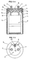
Figs. 1A and 1B show a schematic structure of an
electrolytic condenser or an electrolytic solution
battery to which a pressure release valve in accordance
with the present invention is applied, in which Fig.
1A is a vertical cross sectional view and Fig. 1B is
a plan view. Fig. 2 is a cross sectional view showing
a first preferable aspect of a pressure release valve
applied to the electrolytic condenser or the
electrolytic solution battery shown in Figs. 1A and
1B, in a state of cutting along a line II-II' in Fig.
1B. Fig. 3 is a view as seen from a direction III in
Fig. 2. Fig. 4 is a cross sectional perspective view
of the pressure release valve shown in Fig. 2. Fig.
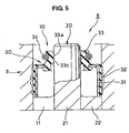
5 is a cross sectional view showing a second preferable
aspect of the pressure release valve applied to the
electrolytic condenser or the electrolytic solution
battery shown in Figs. 1A and 1B, in a state of cutting
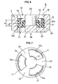
along a line II-II' in Fig. 1B. Fig. 6 is a cross
sectional view showing a third preferable aspect of
the pressure release valve applied to the electrolytic
condenser or the electrolytic solution battery shown
in Figs. 1A and 1B, in a state of cutting along a line
II-II' in Fig. 1B. Fig. 7 is a view as seen from a
direction VII in Fig. 6. Fig. 8 is a cross sectional
view showing a state in which the valve body is not
attached, in accordance with the third aspect. Fig.
9 is a view as seen from a direction IX in Fig. 8. Fig.
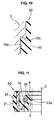
10 is a partly enlarged cross sectional view of Fig.
6. Fig. 11 is a half cross sectional view of the valve
body in the third aspect. Fig. 12 is a schematic view
showing a result obtained by testing a change of a valve
opening pressure on the basis of a temperature. Fig.
13 is a schematic view showing a result obtained by
testing a gas discharging property at a time when the
valve is opened. Fig. 14 is a schematic view showing
a result obtained by testing a change of the valve
opening pressure on the basis of an aging of a rubber
material of a seal lip 33. Fig. 15 is a half cross
sectional view of a valve body using a coil spring in
the third aspect. Fig. 16 is a half cross sectional
view of a valve body using a leaf spring in the third
aspect. Fig. 17 is a cross sectional view showing a
fourth preferable aspect of the pressure release valve
applied to the electrolytic condenser or the
electrolytic solution battery shown in Figs. 1A and
1B, in a state of cutting along a line II-II' in Fig.
1B. Fig. 18 is a cross sectional view showing a state
in which the valve body is disconnected in the forth
aspect, in a state of cutting along a line II-II' in
Fig. 1B. Fig. 19 is a perspective view showing a state
in which the valve body is disconnected in the fourth
aspect, in a state of partly cutting. Fig. 20 is a
cross sectional view showing a state in which the valve
body is opened in the fourth aspect, in a state of cutting
along a line II-II' in Fig. 1B. Fig. 21 is a cross
sectional view showing a fifth preferable aspect of
the pressure release valve applied to the electrolytic
condenser or the electrolytic solution battery shown
in Figs. 1A and 1B, in a state of cutting along the
line II-II' in Fig. 1B. Fig. 22 is a cross sectional
view showing a state in which the valve body is
disconnected in the fifth aspect, in a state of cutting
along a line II-II' in Fig. 1B.
BEST MODE FOR CARRYING OUT THE INVENTION
Figs. 1A and 1B show a schematic structure of an
electrolytic condenser or an electrolytic solution
battery to which a pressure release valve in accordance
with the present invention is applied, in which Fig.
1A is a vertical cross sectional view and Fig. 1B is
a plan view. A main body element 2 of a condenser or
a battery is received within a closed-end cylindrical
case 1 corresponding to a pressure container made of
a metal such as an aluminum or the like, and an upper
end opening portion of the case 1 is closed by a sealing
plate 3 which is formed in a disc shape by a synthetic
resin material or an elastomer having an electrical
insulating property. The main body element 2 is
impregnated with an electrolytic solution sealed
within the case 1.
An outer peripheral portion of the sealing plate
3 is fixed in a sealing manner to a portion between
a caulked portion 1b formed by an upper end portion
of the case 1 being folded back inside, and a draw portion
1a positioned in a lower side of the caulked portion
and continuously formed in a circumferential direction
of the case 1, via an annular gasket 4 made of a
rubber-like elastic material. Further, an outer
periphery of the case 1 is covered by an outer canister
5.
The sealing plate 3 is made of the electrical
insulating synthetic resin material or elastomer, or
a laminated plate material of the synthetic resin
material and the elastomer, as mentioned above.
The synthetic resin material can be selected from
a thermoplastic resin such as a polyolefine resin, a
polyolefine resin polymerized by a metallocene
catalyst, a polyphenylene sulfide, a syndiotactic
polystyrene, a polyamide resin, a polyester resin, a
polyimide resin, a polyamide imide resin, a liquid
crystal resin and the like, a thermosetting resin such
as a phenol resin, an epoxy resin, an imide resin and
the like, and there are appropriately blended a filler,
for example, a fibrous filler such as a glass fiber,
a carbon fiber, a whisker and the like, a particulate
filler such as a carbon particle, a mica, a glass bead
and the like, a reinforcing material, a metal oxide,
a process aid and the like. Further, the elastomer
can be selected from a saturated rubber material such
as a butyl rubber, a halogenoid butyl rubber, a butyl
rubber containing a vinyl group, an ethylene propylene
rubber (EPDM) , a fluorocarbon rubber, an acrylic rubber,
a hydrogenated nitrile rubber and the like, and there
are appropriately blended a cross linking agent, a
filler, a plasticizer, an age resister and the like.
Further, the thermoplastic elastomer can be selected
from an olefin thermoplastic elastomer, an ester
thermoplastic elastomer, an amide thermoplastic
elastomer, and a styrene thermoplastic elastomer such
as a styrene elastomer, for example, a hydrogenated
styrene butadiene block copolymer, a hydrogenated
styrene isoprene block copolymer and the like, and is
manufactured in accordance with a block copolymerizing
method, a graft coplymerizing method, a dynamic
bridging method and the like, and there are
appropriately blended the cross linking agent, the
plasticizer, the age resister, the filler and the like.
In the elastomer such as a mixture of the resin material
and the rubber, the block copolymer, thegraft copolymer
or the like, it is possible to select from a mixture
of a phenol resin and a nitrile rubber hydroxide, an
acrylic rubber, a butyl rubber or a fluorine rubber.
The sealing plate 3 is provided with a pair of
electrode terminals 7 respectively connected to the
element main body 2 via a lead wire 6 so as to extend
in the thickness direction, and is provided with a
pressure release valve 8 in accordance with the present
invention. The electrode terminals 7 and 7 are
integrally formed in a state of being partly buried
in the sealing plate 3 in accordance with an insert
molding, and each of them is prevented from coming off
with respect to the sealing plate 3 by a collar portion
7a formed in an outer peripheral surface.
[First Aspect]
Fig. 2 is a cross sectional view showing a first
preferable aspect of the pressure release valve 8
applied to the electrolytic condenser or the
electrolytic solution battery shown in Figs. 1A and
1B, in a state of cutting along a line II-II' in Fig.
1B, Fig. 3 is a view as seen from a direction III in
Fig. 2, and Fig. 4 is a cross sectional perspective
view of the pressure release valve 8 shown in Fig. 2.
The pressure release valve 8 in accordance with the
present aspect is constituted by a pressure release
port 10 provided in the sealing plate 3, a shaft part
20 coaxially provided within the pressure release port
10 and integrally formed with the sealing plate 3, and
valve body 30 closely fitted and fixed within the
pressure release port 10, as shown in Figs. 2 to 4.
In detail, the shaft part 20 is formed in a columnar
shape, and is fixed to an inner peripheral surface of
an inner end (an end portion of the case 1 in an inner
chamber side) in the circular pressure release port
10. The shaft part 20 and the bridging portion 22 is
made of the same synthetic resin material as that of
the sealing plate 3, that is, are formed as an integral
structure which is continuously formed with the sealing
plate 3. Further, the inner end opening portion in
the pressure release port 10 is divided in the
circumferential direction by the bridging portion 22,
and is formed as three fan-shaped holes 11.
The vale main body 30 is integrally formed on a
reinforcing ring 31 by a rubber-like elastic material,
and has a base portion 32, a seal lip 33 extended from
an inner periphery of one end thereof, and an extension
spring 34 attached to an outer peripheral surface near
a leading end in the seal lip 33. Further, the valve
body 30 is attached to a portion between the pressure
release port 10 and the shaft part 20 in such a manner
that the seal lip 33 is directed to an outer side of
the sealing plate 3.
As a material of the rubber-like elastic material
forming the base portion 32 and the seal lip 33, it
is possible to select a saturated rubber material such
as a butyl rubber, a halogenoid butyl rubber, a butyl
rubber containing a vinyl group, an ethylene propylene
rubber (EPDM), a fluorocarbon rubber, an acrylic rubber,
a hydrogenated nitrile rubber and the like, and there
are appropriately blended a cross linking agent, a
filler, a plasticizer, an age resister and the like.
Further, the thermoplastic elastomer can be selected
from an olefin thermoplastic elastomer, an ester
thermoplastic elastomer, an amide thermoplastic
elastomer, and a styrene thermoplastic elastomer such
as a hydrogenated styrene butadiene block copolymer,
a hydrogenated styrene isoprene block copolymer and
the like, and is manufactured in accordance with a block
copolymerizing method, a graft copolymerizing method,
a dynamic bridging method and the like, and there are
appropriately blended the cross linking agent, the
plasticizer, the age resister, the filler and the like.
In the elastomer such as a mixture of the resin material
and the rubber, the block copolymer, the graft copolymer
or the like, it is possible to select from a mixture
of a phenol resin and a nitrile rubber hydroxide, a
butyl rubber or a fluorine rubber.
The reinforcing ring 31 in the valve body 30 may
be formed in a simple cylindrical shape for downsizing
the valve body 30, however, in view of making a gas
permeable area small, it is preferable to form in an
approximately L-shaped cross section constituted by
a tubular portion 31a and an end wall portion 31b
extending to an inner peripheral side from one end of
the tubular portion 31a, as illustrated.
A material of the reinforcing ring 31 is a metal
material such as an iron, a copper, a titanium, a nickel
and the like, however, it is preferable to employ a
stainless steel, a synthetic resin, a ceramic and the
like which are excellent in a corrosion resistance.
In the case of employing the material having the
corrosion resistance, the reinforcing ring 31 may be
exposed or not be exposed to the electrolytic solution
side, however, in the case of employing the material
having no corrosion resistance, it is necessary to set
the reinforcing ring in a completely buried state so
as to prevent from being exposed to the electrolytic
solution side.
The base portion 32 made of the rubber-like elastic
material is integrally bonded in a vulcanizing manner
to an outer peripheral surface of the tubular portion
31a in the reinforcing ring 31, and a plurality of
protrusions 32a which are continuously provided in the
circumferential direction are formed in an outer
peripheral surface of the base portion 32. Further,
the seal lip 33 made of the rubber-like elastic material
is integrally bonded in a vulcanizing manner to the
end wall portion 31b of the reinforcing ring 31, and
is continuously formed from the base portion 32.
An outer diameter of the tubular portion 31a of
the reinforcing ring 31 is appropriately smaller than
an inner diameter of the pressure release port 10 in
the sealing plate 3, and an outer diameter of the base
portion 32 including the protrusion 32a is
appropriately larger than the inner diameter of the
pressure release port 10 in a state of not being attached.
Accordingly, in a state in which the valve body 30 is
pressure-attached to the sealing plate 3, the base
portion 32 is closely fitted to the inner peripheral
surface of the pressure release port 10 with a proper
collapsing margin, as shown by a two-dot chain line
in Fig. 2, and since a compression amount is particularly
larger in the protrusion 32a, the base portion 32 is
firmly fixed to the pressure release port 10 and achieves
an excellent sealing performance.
Inner diameters of the end wall portion 31b of
the reinforcing ring 31 and a heel-shaped end portion
33b of the seal lip 33 bonded to the end wall portion
31b are appropriately larger than the outer diameter
of the shaft part 20, and an inner diameter of the lip
portion 33a formed in an inner periphery of the leading
end of the seal lip 33 is appropriately smaller than
the outer diameter of the shaft part 20 in a state of
not being attached as shown in Fig. 4. Further, the
extension spring 34 is formed in an annular shape by
bonding both ends of a coil spring, is fitted to a
circular peripheral groove formed in an outer
peripheral surface of the seal lip 33 in a suitably
widened state, and compensates for a softening of the
seal lip 33 at a high temperature and a reduction of
the tensional force due to a deterioration with age
(aging) of the rubber material. As a material of the
extension spring 34, a metal material such as an iron,
a copper, a titanium, a nickel and the like is selected,
however, it is preferable to employ a stainless steel
which is excellent in a corrosion resistance.
Accordingly, in the attached state of the valve
body 30 to the sealing plate 3, as shown in Fig. 2,
the seal lip 33 is closely contacted with the outer
peripheral surface of the shaft part 20 by a tensile
force of its own elasticity and a tensile force of the
extension spring 34, in a state in which the lip portion
33a has a proper collapsing margin shown by a broken
line in Fig. 2. In this case, as a means for
compensating for the reduction in the tensional force
of the seal lip 33 due to the temperature and the aging,
the other spring than the extension spring 34 may be
employed as shown in Figs. 15 and 16 mentioned below
as far as the means is an elastic body having a fastening
effect. Further, in some set values of the valve
opening pressure, the temperature condition and the
like, it is not always necessary to provide such a
spring.
The valve body 30 can be pressure-inserted and
attached to the pressure release port 10 of the sealing
plate 3 after filling the electrolytic solution into
the case 1 in a final assembling step of the condenser
or the battery. Accordingly, it is possible to
restrict the evaporation of the electrolytic solution
generated in the assembling process to the minimum and
it is possible to stabilize the quality of the product.
The pressure release valve 8 provided with the
structure mentioned above is opened in the case that
the internal pressure of the case 1 is increased more
than a predetermined value, thereby releasing the
internal pressure to the atmospheric air and preventing
the case 1 from being broken due to an abnormal increase
of the internal pressure.
The pressure of the gas generated on the basis
of the reaction of the electrolytic solution sealed
within the case 1 (the internal pressure of the case
1) reaches an inner peripheral space of the valve body
30 within the pressure release port 10 via the fan-shaped
hole 11, and the internal pressure is applied to the
inner peripheral surface of the seal lip 33 as a valve
opening force for opening the seal lip 33 to an outer
peripheral side. Accordingly, when the valve opening
force on the basis of the internal pressure of the case
1 becomes larger than a valve closing force on the basis
of the elasticity of the seal lip 33 and the tensional
force of the extension spring 34, the lip portion 33a
of the seal lip 33 is apart from an outer peripheral
surface of the shaft part 20 so as to be in a valve
opening state, and releases the internal pressure of
the case 1 to the atmospheric air in the external via
the pressure release port 10. Further, since the heat
within the case 1 is also discharged to the atmospheric
air at this time, it is possible to prevent the condenser
or the battery from being reduced in function due to
the heat. Further, since the valve is closed
immediately on the basis of a restoring force generated
by the elasticity of the seal lip 33 and the tensional
force of the extension spring 34 in the case that the
internal pressure is released, it is possible to shut
off the intrusion of the water vapor and the foreign
matter from the external.
In this case, the pressure value (the valve opening
pressure) at a time when the seal lip 33 of the valve
body 30 is opened on the basis of the increase of the
internal pressure of the case 1 can be optionally set
on the basis of the inner diameter and the cross
sectional shape of the seal lip 33, the outer diameter
of the shaft part 20, the tensional force of the
extension spring 34 and the like. accordingly, the
valve opening pressure can be suitably set while taking
the value of the gas pressure caused by the heat
generated in the normal use state into consideration.
In this case, it is preferable that the working
of the outer peripheral surface of the shaft part 20
is made such that the contact area of the seal lip 33
is not communicated in the axial direction, in view
of the sealing property achieved by the seal lip 33.
[Second Aspect]
Fig. 5 is a cross sectional view showing a second
preferable aspect of the pressure release valve 8
applied to the electrolytic condenser or the
electrolytic solution battery shown in Figs. 1A and
1B, in a state of cutting along a line II-II' in Fig.
1B, as an example of modifying the cross sectional shape
of the seal lip 33. In the pressure release valve 8
in accordance with this aspect, a plurality of (two
in the illustrated embodiment) lip portions 33a and
33c are formed in an inner periphery of a leading end
of the seal lip 33 in the valve body 30. Accordingly,
the sealing property in the valve closing state is
further improved, and the valve opening pressure can
be made higher due to the existence of the lip portion
33c in comparison with the structure shown in Figs.
2 and 3.
Further, the internal pressure of the case 1 is
also applied to the direction of pulling out the valve
body 30 from the pressure release port 10, however,
a sufficient pressure contact force caused by the
collapsing margin of the base portion 32 is set to the
inner peripheral surface of the pressure release port
10 in such a manner as to prevent the valve body 30
from easily moving in the pulling-out direction by such
a pressure as the valve opening pressure of the seal
lip 33.
When the internal pressure of the case 1 is
decreased to the predetermined value or less on the
basis of the valve opening of the seal lip 33 as mentioned
above, the seal lip 33 is operated so as to close the
valve on the basis of the valve closing force generated
by its own elasticity and the tensional force of the
extension spring 34, and the lip portion 33a is closely
contacted with the outer peripheral surface of the shaft
part 20 so as to close the pressure release port 10.
In other words, since the internal pressure of
the case 1 is the set valve opening pressure or less
under the normal use state, there is achieved the valve
closing state in which the seal lip 33 is in close contact
with the shaft part 20, and it is possible to prevent
the water vapor and the foreign matter from making an
intrusion from the external portion. Further, as
mentioned above, since the seal lip 33 is in the valve
opening state only in the case that the expanding force
caused by the internal pressure is increased more than
the valve opening pressure, it is possible to restrict
the reduction of the electrolytic solution due to the
evaporation or the like to the minimum, and it is
possible to improve the service life of the condenser
or the battery.
In this case, in each of the aspects mentioned
above, the sealing plate 3 is formed by the synthetic
resin material, the elastomer or the like as described
above, and in order to make a mold release after molding
easy, an inner peripheral surface 12 of the pressure
release port 10 is formed with a slope that the diameter
of the inner peripheral surface 12 varies slightly
larger in the metal mold extracting direction, that
is, toward an outer opening end portion corresponding
to the opposite side to the bridging portion 22.
Further, a stress relief with age is generated in the
rubber-like elastic material constituting the base
portion 32 of the valve body 30, and a permanent strain
with age is generated in the inner peripheral surface
12 itself of the pressure release port 10 made of the
synthetic resin material due to the application of the
expanding force from the base portion 32. Accordingly,
there is fear that the valve body 30 tends to be pulled
out from the pressure release port 10.
[Third Aspect]
Fig. 6 is a cross sectional view showing a third
preferable aspect of the pressure release valve 8
preventing the valve body 30 from being pulled out,
taking the above matters into consideration, in a state
of cutting along a line II-II' in Fig. 1B, and Fig.
7 is a view as seen from a direction VII in Fig. 6.
Further, Fig. 8 is a cross sectional view showing a
state in which the valve body 30 is not attached, in
accordance with this aspect, Fig. 9 is a view as seen
from a direction IX in Fig. 8, Fig. 10 is a cross sectional
view showing a part of Fig. 6 in an enlarged manner,
and Fig. 11 is a half cross sectional view of the valve
body 30 in accordance with this aspect. The pressure
release valve 8 in accordance with this aspect is
structured such that a recess portion 12a is formed
in the inner peripheral surface 12 of the pressure
release port 10 of the sealing plate 3 formed by the
synthetic resin material, the elastomer or the like.
The recess portion 12a is formed in a stepped shape
in correspondence to an opening range of each of the
fan-shaped holes 11 between the bridging portions 22
radially extending from a base end portion 21 of the
shaft part 20 at a uniform interval in the
circumferential direction, and is extended to an
intermediate portion of an attaching position of the
valve body 30 in the axial direction from an inner end
(a lower end in Fig. 6) in the inner peripheral surface
12 of the pressure release port 10.
For details, on the assumption that an axial length
of the recess portion 12a in the fitting portion of
the base portion 32 of the valve body 30 is set to λ
1, and an axial length of a pressure contact portion
32b (mentionedbelow) of thevalvebody 30 closely fitted
to the inner peripheral surface 12 of the pressure
release port 10 is set to λ2, as shown in Fig. 6, the
value λ1 is about 20 to 80 % of the value λ2. Further,
on the assumption that an opening range of the fan-shaped
hole 11 with respect to the circumferential direction
is set to 1, and a forming range of the recess portion
12a with respect to the circumferential direction is
set to 2, as shown in Fig. 9, a relation 1 ≧ 2
≧ 1 degree is established. Further, a plurality of
recess portions 12a may be formed so as to be arranged
at positions corresponding to the opening ranges
1 of the respective fan-shaped holes 11 in the
circumferential direction. Further, as shown in Fig.
10 in an enlarged manner, it is preferable to form an
end portion 12b of the recess portion 12a positioned
in a middle portion of the inner peripheral surface
12 of the pressure release port 10 at an acute angle
with respect to the inner peripheral surface 12, and
a smaller chamfer in a corner portion is better.
In this case, in the present aspect, the valve
body 30 is formed in a slightly different shape from
that of the first or second aspect described above,
however, has the same basic structure. In other words,
the valve body 30 is integrally formed on the reinforcing
ring 31 by the rubber-like elastic material, and has
a base portion 32 in which the reinforcing ring 31 is
buried, a seal lip 33 extended from one end inner
periphery thereof, and an extension spring 34 attached
to the outer peripheral surface near the leading end
in the seal lip 33. Further, as shown in Fig. 8, a
cylindrical surface-shaped pressure contact portion
32b having an appropriately larger diameter than the
inner peripheral surface 12 of the pressure release
port 10 in a state of not being attached is formed in
an outer peripheral surface of the base portion 32.
The rubber-like elastic material forming the base
portion 32 and the seal lip 33 of the valve body 30
can be selected from the saturated rubber, the
thermoplastic elastomer, the mixture of the resin
material and the rubber, the block copolymer, the graft
copolymer and the like, as described above in the first
aspect. The inner peripheral lip 33a of the seal lip
33 is set to be R0.2 or more in order to secure a desired
close contact width with respect to the outer peripheral
surface of the shaft part 20, and an angle α of an
outer taper surface and an angle β of an inner taper
surface of the lip 33a with respect to the cylindrical
surface around an axis O are set between 5 and 90 degree,
as shown in Fig. 11. Further, either the angles α
or β may be set to be relatively larger.
In this case, the recess portion 12a in the inner
peripheral surface 12 of the pressure release port 10
is formed by a metal mold element which can be pulled
out to an inner side of the sealing plate 3, at a time
of forming the sealing plate 3. In other words, the
metal mold element for forming the inner peripheral
surface 12 of the pressure release port 10 and the outer
peripheral surface of the shaft part 20 is pulled out
to an upper side in Figs. 6 and 8 at a time of releasing
the mold, however, the metal mold element for forming
the recess portion 12a is pulled out to a lower side
in Figs. 6 and 8 at a time of releasing the mold.
Accordingly, it is possible to form the recess portion
12a without generating difficulty in releasing the
mold.
In the structure mentioned above, the valve body
30 is pressure-inserted to a portion between the
pressure release port 10 and the shaft part 20 from
the outside of the sealing plate 3, in such a manner
that the seal lip 33 is directed to the outside of the
sealing plate 3, as shown in Fig. 8. At this time,
the pressure contact portion 32b in the base portion
32 of the valve body 30 is exposed to a diametrical
compression between the reinforcing ring 31 buried in
the base portion 32 and the inner peripheral surface
12 of the pressure release port 10. In other words,
a collapsing margin corresponding to a difference
between the inner diameter of the pressure release port
10 and the outer diameter of the pressure contact portion
32b in the base portion 32 is applied to the pressure
contact portion 32b. However, the portion reaching
each of the recess portions 12a formed in the inner
peripheral surface 12 of the pressure release port 10
in the pressure contact portion 32b is elastically
restored from the compression state so as to be in a
state of protruding into each of the recess portions
12a, in a process that the inner end (the lower end)
of the base portion 32 is pressure-inserted until the
inner end of the base portion 32 is brought into contact
with the bridging portion 22.
Accordingly, once the valve body 30 is
pressure-inserted to the pressure release port 10 from
the outside of the sealing plate 3 until the inner end
(the lower end) of the base portion 32 is brought into
contact with the bridging portion 22, the valve body
can not be easily detached on the basis of the fitting
between the recess portion 12a and the pressure contact
portion 32b. Accordingly, even in the case that the
inner peripheral surface 12 of the pressure release
port 10 has a slope that the diameter varies slightly
larger toward the opening end portion in the opposite
side to the bridging portion 22, in order to make it
easy to release the mold after forming the sealing plate
3 with the synthetic resin material, or even in the
case that the permanent strain with age is generated
in the base portion 32 of the valve body 30 and the
inner peripheral surface 12 of the pressure release
port 10 due to a long time use, the disengaging load
applied in the direction in which the valve body 30
is pulled out from the pressure release port 10 is
maintained in a high state. In particular, a come-off
prevention effect becomes higher by forming the end
portion 12b of the recess portion 12a at an acute angle
with respect to the inner peripheral surface 12, as
shown in Fig. 10.
Further, it is not necessary to make the axial
length of the base portion 32 of the valve body 30 longer
for the purpose of increasing the disengaging load,
so that it is possible to make the axial size of the
valve body 30 small, and the resistance of
pressure-insertion to the pressure release port 10 at
a time of attaching becomes small.
The extension spring 34 is structured, in the same
manner as the first and second aspects, such as to
compensate for the reduction in the tensional force
of the seal lip at a high temperature, and reduce a
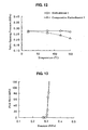
temperature dependence of the sealing property. Fig.
12 is a schematic view showing a result obtained by
testing the change of the valve opening pressure in
accordance with the temperature, with respect to an
embodiment 1 provided with the structure in accordance
with the third aspect shown in Fig. 6, and a comparative
embodiment 1 in which an initial tensional force of
the seal lip 33 itself is set to be equal to that of
the embodiment 1, without using the extension spring
34. As is apparent from Fig. 12, the reduction in the
valve opening pressure appears in accordance with the
increase of the temperature, in the comparative
embodiment 1 using no extension spring 34, however,
the valve opening pressure is kept appropriately
constant in a wide temperature range, in the embodiment
1 having the extension spring 34.
Fig. 13 is a schematic view showing a result
obtained by testing a gas discharging property at a
time of opening thevalve, with respect to the embodiment
1 provided with the structure in accordance with the
third aspect shown in Fig. 6. As shown in Fig. 13,
when the pressure of the gas generated by the reaction
of the electrolytic solution is increased to the valve
opening pressure (about 0.28 MPa in this example),
whereby the lip portion 33a of the seal lip 33 is
disconnected from the outer peripheral surface of the
shaft part 20 so as to be in the valve opening state,
a large flow rate of gas is discharged by the thereafter
slight pressure increase. Accordingly, it is not
necessary to provide with the other explosion proofing
valve or the like, and the structure is extremely
effective as the pressure releasing means for the
large-size capacitor or condenser in which a large
amount of gas is generated.
Fig. 14 is a schematic view showing a result
obtained by testing a change in the valve opening
pressure in accordance with aging of the rubber material
of the seal lip 33, with respect to the embodiment 1
provided with the structure in accordance with the third
aspect shown in Fig. 6, and the comparative embodiment
1 in which the initial tensional force of the seal lip
33 itself is set to be equal to that of the embodiment
1 without using the extension spring 34. The test is
executed by aging the rubber material of the seal lip
33 with age by leaving it at a temperature of 120 °C
and measuring the valve opening pressure. As is
apparent from Fig. 14, it is known that the reduction
in the valve opening pressure due to the aging is
restricted in the embodiment 1 in which the tensional
force is supplemented by the extension spring 34, in
comparison with the comparative embodiment 1.
Figs. 15 and 16 show an example in which the other
spring than the extension spring 34 is employed as the
tensional force supplementing means of the seal lip
33 against the high temperature and the aging. For
example, the valve body 30 shown in Fig. 15 is provided
with a spring 34' extending spirally in the
circumferential direction, in the lip portion 33a of
the seal lip 33, and the valve body 30 shown in Fig.
16 is provided with an annular leaf spring 34" having
an approximately U-shaped bent cross section, from the
inner periphery of the base portion 32 to the outer
periphery of the lip portion 33a of the seal lip 33,
however, the structure is not limited to those as far
as an elastic body having a fastening effect. Further,
the material of the springs 34' and 34" can be a metal
material such as an iron, a copper, a titanium, a nickel
and the like, and preferably is a stainless steel having
acorrosionresistance. Further, the extension spring
34 and the other springs 34' and 34" are not necessarily
provided in some set values of the valve opening pressure
and some tensional forces of the seal lip 33 itself.
In the case that the pressure release valve 8 in
accordance with each of the aspects mentioned above
is provided in an electric double layer condenser
(capacitor) using a nonaqueous electrolytic solution
(a fourth onium BF4 propylene carbonate solution or
the like) , there is a risk that the water vapor in the
atmosphere transmits through the rubber-like elastic
material of the valve body 30 in some rubber-like elastic
materials of the valve body 30 so as to deteriorate
the property of the condenser, and the service life
becomes short.
For details, the electric double layer condenser
includes two types comprising a type using an aqueous
electrolytic solution (a vitriolic water solution or
the like) and a type using the nonaqueous electrolytic
solution mentioned above. In this case, the electric
double layer condenser using the nonaqueous
electrolytic solution is more excellent, taking into
consideration a height of a generated voltage and a
width of an allowable temperature range. However, in
the type using the nonaqueous electrolytic solution,
the service life which is said permanent is not
established, if the water vapor makes an intrusion into
the container. This is because the intruded water is
electrolyzed so as to lower an electric strength, and
is hydrolyzed with the component of the electrolytic
solution so as to promote the deterioration. Further,
if the electrolytic solution is hydrolyzed, a carbon
dioxide gas is generated so as to cover a surface of
an inner portion of an activated carbon electrode, so
that a reduction in a capacitance is generated.
The rubber-like elastic material forming the base
portion 32 of the valve body 30 and the seal lip 33
is selected from the saturated rubber, the
thermoplastic elastomer, the mixture of the resin
material and the rubber, the block copolymer, the graft
copolymer and the like, as described above in the first
aspect, and generally employed are an ethylene
propylene rubber (EPDM) and a silicone rubber which
are excellent in a weather resistance, however, in the
case of the pressure release valve of the electric double
layer capacitor using the nonaqueous electrolytic
solution, a butyl rubber is used for the reason mentioned
above. Because the butyl rubber has a sufficiently
lower water vapor permeability in comparison with the
EPDM. Accordingly, by using the butyl rubber for the
rubber-like elastic material of the valve body 30, it
is possible to reduce the water vapor from making an
intrusion into the container, it is possible to prevent
the reduction of the electric strength due to the
electrolysis of the intruded water, the deterioration
of the electrolytic solution due to the hydrolysis and
the reduction of the capacitance, and it is possible
to improve the service life of the electric double layer
capacitor.
Table 1 shows a result obtained by testing for
verifying a water vapor transmission factor of the
pressure release valve using the butyl rubber and the
pressure release valve using the EPDM. This test is
executed by leaving a sealed container (an embodiment
2) provided with the pressure release valve using the
butyl rubber as the rubber-like elastic material, and
a sealed container (a comparative embodiment 2)
provided with the pressure release valve using the EPDM
as the rubber-like elastic material, in the atmosphere
having a
temperature 60 °C and a humidity 90 RH. The
structure of the pressure release valve is the structure
shown in Fig. 6. Further, a drying agent is set for
replacing the air in the sealed container by the dry
air at an early stage, and the completely sealed
container having the same structure is simultaneously
left in the atmosphere mentioned above as a reference
together with the sealed containers in accordance with
the
embodiment 2 and the
comparative embodiment 2.
Then, a change in weight is measured after 2000 hour
has passed, with respect to each of them. As a result,
as shown in Table 1, the water vapor transmission factor
is about a quarter in the
embodiment 2 using the butyl
rubber for the rubber-like elastic material of the valve
body, in comparison with the
comparative embodiment
2 using the EPDM.
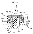
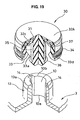
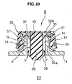
Fig. 17 is a cross sectional view showing a fourth
aspect of the pressure release valve 8 applied to the
electrolytic condenser or the electrolytic solution
battery shown in Figs. 1A and 1B, in a state of cutting
along a line II-II' in Fig. 1B, Fig. 18 is a cross
sectional view showing a state in which the valve body
30 is disconnected in the present aspect, in a state
of cutting along a line II-II' in Fig. 1B, Fig. 19 is
a perspective view showing a state in which the valve
body is disconnected in the present aspect, in a state
of partly cutting, and Fig. 20 is a cross sectional
view showing a state in which the valve body 30 is opened
in the present aspect, in a state of cutting along a
line II-II' in Fig. 1B. The pressure release valve
8 in accordance with the present aspect is constituted
by a tubular holding portion 13 formed in a protruding
manner in the sealing plate 3 and having the pressure
release port 10 in the inner periphery, and a valve
body 30 locking to the tubular holding portion 13.
For details, as is most apparently shown in Figs.
18 and 19, the tubular holding portion 13 is formed
in a cylindrical shape protruding toward the outside
of the case 1 from the sealing plate 3, and a tapered
chamfer 13a is applied to an outer peripheral surface
of a leading end thereof. The pressure release port
10 in the inner periphery is formed so as to extend
through the sealing plate 3. The pressure release port
10 is formed in a circular hole shape, and a pair of
groove-shaped pressure passages 14 continuously
extending to an outer end opening portion 10b from an
inner end opening portion 10a is formed in symmetrical
positions at 180 degree in the circumferential
direction.
The valve body 30 is integrally formed on the
reinforcing ring 31 with the rubber-like elastic
material, and has a disc-shaped base portion 32A formed
such that the reinforcing ring 31 is buried, a seal
lip 33 cylindrically extended from an outer peripheral
portion thereof, an extension spring 34 attached to
an outer peripheral surface near a leading end in the
seal lip 33, a shaft part 35 coaxially formed in an
inner peripheral side of the seal lip 33 and extending
from a center portion of the base portion 32A, and a
collar-shaped locking portion 36 formed in an outer
periphery of a leading end of the shaft part 35. Further,
a plurality of groove-shaped pressure passages 37
extending in a diametrical direction are formed at a
uniform interval in the circumferential direction, in
an inner surface (a lower surface in the drawing) of
the base portion 32A.
The reinforcing ring 31 is press-molded in a disc
shape such that an outer peripheral portion is bent
so as to extend to a part of the seal lip 33, and an
inner peripheral portion of the reinforcing ring 31
is provided with a circular hole 31c for improving the
material flow at a time of forming by the rubber-like
elastic material and increasing a bonding strength with
the rubber-like elastic material.
As shown in Fig. 18, a length L1 from the inner
surface 32c of the base portion 32A in the valve body
30 to the locking portion 36 in the shaft part 35 is
approximately equal to a sum of a protruding height
H of the tubular holding portion 13 and a thickness
T of the sealing plate 3. Further, an axial length
L2 from the inner surface 32c of the base portion 32A
to the leading end of the seal lip 33 is shorter than
the protruding height H of the tubular holding portion
13.
An inner diameter of the lip portion 33a formed
in the inner periphery of the leading end of the seal
lip 33 is appropriately smaller than the outer diameter
of the tubular holding portion 13, in a non-attached
(disengaged) state shown in Figs. 18 and 19. Further,
the extension spring 34 is formed in a ring shape by
bonding both ends of the coil spring, and is fitted
to the circumferential groove 33d formed in the outer
peripheral surface of the seal lip 33 in a suitably
expanded state.
As shown in Fig. 18, an outer diameter 1 of the
shaft part 35 is slightly smaller than an inner diameter
2 of the pressure release port 10, and an outer
peripheral edge of the locking portion 36 is slightly
larger than the inner diameter of the pressure release
port 10 and is arranged in an inner peripheral side
of a diametrical position of a groove bottom of the
pressure passage 14. Further, an outer peripheral
surface 35a from a leading end of the shaft part 35
to the locking portion 36 is formed in a taper shape
in which the leading end side of the shaft part 35 has
a smaller diameter, and a back surface 36a of the locking
portion 36 is formed in a flat surface approximately
perpendicular to the axis of the shaft part 35.
The valve body 30 can be easily attached only by
pressure-inserting to the tubular holding portion 13
from a separated state shown in Figs. 18 and 19 so as
to insert the shaft part 35 to the pressure release
port 10, because the lip portion 33a in the inner
periphery of the leading end of the seal lip 33 is brought
into close contact with the outer peripheral surface
of the tubular holding portion 13 in the sealing plate
3, the shaft part 35 is loosely fitted to the pressure
release port 10, the inner surface 32c of the base
portion 32A is brought into contact with the leading
end surface of the tubular holding portion 13, and the
locking portion 36 is engaged with the edge portion
of the inner end opening portion 10a in the pressure
release port 10, as shown in Figs. 17.
Further, the attaching work can be executed in
a final assembly step of the condenser or the battery,
after injecting the electrolytic solution into the case
1 shown in Figs. 1A and 1B. Accordingly, it is possible
to restrict the evaporation of the electrolytic
solution generated in the assembling process to the
minimum, and it is possible to intend to stabilize the
quality of the product.
In the attached state shown in Fig. 17, the seal
lip 33 exists in such a manner that the lip portion
33a is in close contact with the outer peripheral surface
of the tubular holding portion 13 with a proper
collapsing margin, on the basis of the tensional force
of its own elasticity and the tensional force of the
extension spring 34, and the base portion 32A closes
the outer end opening portion 10b of the pressure release
port 10. Further, since the outer peripheral edge of
the locking portion 36 exists in the inner peripheral
side of the diametrical position of the groove bottom
of the pressure passage 14 formed in the pressure release
port 10, the inner end of the pressure passage 14 is
exposed from the outer periphery of the locking portion
36 so as to be open to an inner space of the sealing
plate 3 (an inner space of the case 1) S2, in this attached
state.
In this case, it is possible to suitably select
the material of the reinforcing ring 31 in the valve
body 30, the material of the rubber-like elastic
material forming the base portion 32A and the seal lip
33, the material of the extension spring 34 and the
like from the material described in the first aspect.
Further, in this aspect, the elastic body having a
fastening effect can be used as the means for
compensating the reduction of the tensional force of
the seal lip 33, in addition to the extension spring
34, and the other springs can be used as described above
in Figs. 15 and 16.
In the pressure release valve 8 provided with the
structure mentioned above, the pressure of the gas
generated by the reaction of the electrolytic solution
sealed within the case 1 shown in Figs. 1A and 1B (the
internal pressure of the case 1) reaches an annular
space S1 between the outer peripheral surface of the
tubular holding portion 13 and the seal lip 33 of the
valve body 30 from the case internal space S2 shown
in Figs. 17 and 20, via the pressure passage 14 open
to the inner space S2 in the 180 degree symmetrical
position in the outer periphery of the locking portion
36, the gap G between the pressure release port 10 and
the shaft part 35, and a plurality of pressure passages
37 formed in the inner surface 32c of the base portion
32A in the valve body 30. The internal pressure is
applied as a valve opening force for opening the seal
lip 33 to an outer peripheral side, to the inner
peripheral surface of the seal lip 33 from the annular
space S1.
Further, since the inner pressure of the case 1
is applied in the direction of pulling out the valve
body 30 from the tubular holding portion 13, the locking
portion 36 in a state of being engaged with the edge
portion of the inner end opening portion 10a of the
pressure release port 10 is exposed to a deformation.
Further, pressure (breakaway pressure) required for
canceling an engagement state with the inner end opening
portion 10a of the pressure release port 10 by the
locking portion 36 being deformed so as to be completely
inverted, is set to a predetermined higher pressure
value than a pressure value (valve opening pressure)
required for operating the seal lip 33 so as to open
the valve and making the seal lip 33 to move up from
the outer peripheral surface of the tubular holding
portion 13. Further, the valve opening pressure and
the breakaway pressure can be suitably set in
correspondence to an inner diameter, thickness and a
cross sectional shape of the seal lip 33, an outer
diameter of the tubular holding portion 13, tensional
force of the extension spring 34, thickness and a shape
of the locking portion 36 and the like.
Accordingly, in accordance with the pressure
release valve 8, in the case that the valve opening
force generated by the internal pressure of the case
1 becomes larger than the valve closing force obtained
by the elasticity of the seal lip 33 itself and the
tensional force of the extension spring 34, the lip
portion 33a of the seal lip 33 comes apart from the
outer peripheral surface of the tubular holding portion
13 so as to generate the valve opening state, and the
internal pressure P is released to the atmospheric air
in the external through the pressure passages 14 and
37 while expanding the lip portion 33a to the outer
peripheral side, as shown by a thick arrow in Fig. 20.
Further, at this time, since the heat within the case
1 is also discharged to the atmospheric air, it is
possible to prevent the reduction in function of the
condenser or the battery due to the heat.
When the internal pressure P is released by the
valve opening of the seal lip 33, and descends to be
a predetermined value or less, the seal lip 33
immediately closes the valve by the restoring force
obtained by its own elasticity and the tensional force
of the extension spring 34, and the lip portion 33a
is brought into close contact with the outer peripheral
surface of the tubular holding portion 13.
Accordingly, it is possible to shut off the intrusion
of the water vapor and the foreign matter from the
external, and it is possible to prevent the electrolytic
solution from being reduced due to the evaporation.
Further, since the internal pressure P is the set
valve of opening pressure or less under the normal use
state, the seal lip 33 is in the valve closing state
of being in close contact with the tubular holding
portion 13 as shown in Fig. 17, and it is possible to
prevent the water vapor and the foreign matter from
making an intrusion from the external. Further, as
mentioned above, since the seal lip 33 is in the valve
open state only in the case that the internal pressure
is increased more than the valve opening pressure, it
is possible to restrict the reduction of the
electrolytic solution due to the evaporation or the
like to the minimum, and it is possible to improve the
service life of the condenser or the battery.
Further, in the case that the internal pressure
P of the case 1 is suddenly increased due to generation
of some kind of abnormalities, and an ascension rate
of the internal pressure P is larger than a pressure
release speed generated by the valve opening of the
seal lip 33, a deforming force applied to the locking
portion 36 in accordance with the increase of the
internal pressure P becomes large. Further, when the
internal pressure P is increased more than the set
breakaway pressure, the locking portion 36 is deformed
so as to be completely inverted, whereby the engagement
state with the inner end opening portion 10a of the
pressure release port 10 is canceled. Accordingly,
the valve body 30 breaks away from the tubular holding
portion 13 as shown in Figs. 18 and 19 on the basis
of the internal pressure P applied to the leading end
of the shaft part 35, the inner surface 32c of the base
portion 32A and the like. accordingly, the pressure
release port 10 is completely open to the external,
rapidly releases the internal pressure P to the
atmospheric air and prevents the case from being
exploded.
In other words, the pressure release valve 8 having
the structure mentioned above has a primary function
of releasing the internal pressure P at a time when
the internal pressure P is increased to some extent,
and a function serving as an explosion proofing valve,
at the same time. Further, since the valve body 30
is formed in a shape which is put on the tubular holding
portion 13 constituting the pressure release port 10
from the above, the foreign matter, the liquid and the
like do not pile up in the upper portion of the pressure
release port 10 as in the case that the valve body 30
is attached in the pressure release port 10, so that
it is possible to achieve a stable function.
[Fifth Aspect]
Fig. 21 is a cross sectional view showing a fifth
aspect of the pressure release valve 8 applied to the
electrolytic condenser or the electrolytic solution
battery shown in Figs. 1A and 1B, in a state of cutting
along the line II-II' in Fig. 1B, and Fig. 22 is a cross
sectional view showing a state in which the valve body
30 is disconnected in the present aspect, in a state
of cutting along a line II-II' in Fig. 1B. The pressure
release valve 8 in accordance with the present aspect
is different from the fourth aspect shown in Figs. 17
to 20, in the locking structure of the valve body 30.
As shown in Fig. 22, a length L3 from the inner
surface 32c of the base portion 32A in the valve body
30 to the leading end of the shaft part 35 is equal
to or less than a length corresponding to a sum of the
protruding height H of the tubular holding portion 13
and the thickness T of the sealing plate 3, and the
outer diameter of the locking portion 36 formed in the
outer periphery of the leading end of the shaft part
35 is formed at an appropriately larger diameter than
the inner diameter of the pressure release port 10 in
such a manner as to be pressure-inserted to the inner
surface of the pressure release port 10 with a desired
collapsing margin.
In the attached state shown in Fig. 21, the seal
lip 33 exists in such a manner that the lip portion
33a in the inner periphery is in close contact with
the outer peripheral surface of the tubular holding
portion 13 with a proper collapsing margin, on the basis
of the tensional force of its own elasticity and the
tensional force of the extension spring 34, and the
base portion 32A closes the outer end opening portion
10b of the pressure release port 10. Further, since
the outer peripheral surface of the locking portion
36 is in a pressure contact with the inner surface of
the pressure release port 10 with a predetermined
collapsing margin, and a part thereof is in a slightly
protruded state to such a degree of not closing the
pressure passage 14 formed in the pressure release port
10, as shown by a broken line.
The structures of the other portions are the same
as those of the fourth aspect shown in Figs. 17 to 20.
In accordance with the present aspect, the valve
body 30 is locked to the tubular holding portion 13
on the basis of a friction force of the locking portion
36 with respect to the inner surface of the pressure
release port 10. Further, a pressure (a breakaway
pressure) required for the valve body 30 to break away
from the tubular holding portion 13 against the friction
force is set to a predetermined higher pressure value
than a pressure value (a valve opening pressure)
required for operating the seal lip 33 so as to open
the valve and making the seal lip 33 to move up from
the outer peripheral surface of the tubular holding
portion 13. Further, the breakaway pressure can be
set in correspondence to a collapsing margin, a cross
sectional shape and the like of the locking portion
36.
Accordingly, in the same manner as the fourth
aspect, in the case that the valve opening force
generated by the internal pressure of the case 1 shown
in Fig. 1 becomes larger than the valve closing force
obtained by the elasticity of the seal lip 33 itself
and the tensional force of the extension spring 34,
the seal lip 33 opens the valve so as to release the
internal pressure to the atmospheric air. When the
internal pressure descends to be a predetermined valve
of opening pressure or less, the seal lip 33 closes
the valve so as to shut off the intrusion of the water
vapor and the foreign matter from the external, and
prevent the electrolytic solution from being reduced
due to the evaporation. Further, in the case that the
internal pressure of the case 1 is increased more than
the set breakaway pressure due to generation of some
kind of abnormalities, the locking portion 36 slips
with respect to the inner surface of the pressure release
port 10 on the basis of the moving force in the breakaway
direction due to the internal pressure applied to the
leading end of the shaft part 35, the inner surface
32c of the base portion 32A and the like, and the valve
body 30 breaks away from the tubular holding portion
13 so as to suddenly release the internal pressure to
the atmospheric air and prevent the case 1 from being
exploded.
In this case, in each of the aspects mentioned
above, the description is given of the structure in
which the present invention is applied to the sealing
plate sealing the case of the condenser or the battery,
however, the present invention can be applied to a
pressure release mechanism of the other general
pressure containers.
INDUSTRIAL APPLICABILITY
In accordance with the pressure release valve on
the basis of the first aspect of the present invention,
since the valve body which is closely fitted and fixed
within the pressure release port provided in the sealing
plate sealed in the opening portion of the pressure
container has the seal lip which is closely contacted
with the outer peripheral surface of the shaft part
coaxially provided within the pressure release port
and is directed to the outside of the pressure container,
the seal lip is operated so as to open the valve, thereby
releasing the internal pressure to the atmospheric air,
in the case that the internal pressure of the pressure
container is increased more than the predetermined
value. Accordingly, it is possible to prevent the
pressure container from being broken due to the increase
of the internal pressure, and it is possible to
optionally set the valve opening pressure on the basis
of the tensional force of the seal lip. Further, since
the seal lip immediately closes the valve in the case
that the internal pressure is released, it is possible
to shut off the intrusion of the foreign matter from
the external, and it is possible to restrict the
discharge of the gas or the like within the pressure
container to the minimum.
In accordance with the pressure release valve on
the basis of the second aspect of the present invention,
since the seal lip is operated so as to open the valve,
thereby releasing the internal pressure to the
atmospheric air, in the case that the internal pressure
of the pressure container is increased more than the
predetermined value, it is possible to restrict the
internal pressure to be a fixed value or less so as
to prevent the pressure container from being broken,
and it is possible to optionally set the valve opening
pressure on the basis of the tensional force of the
seal lip. Accordingly, since the seal lip immediately
closes the valve in the case that the internal pressure
is reduced, it is possible to shut off the intrusion
of the foreign matter from the external, and it is
possible to restrict the discharge of the gas or the
like within the pressure container to the minimum.
Further, in the case that the internal pressure is
rapidly and abnormally increased, the valve body breaks
away from the tubular holding portion so as to completely
release the pressure release port, and functions as
the explosion proofing valve for preventing the
pressure container from being exploded, so that it is
not necessary to additionally provide with the
explosion proofing valve.
In accordance with the pressure release valve on
the basis of the third aspect of the present invention,
the following effect can be obtained in addition to
the effects obtained by the first aspect. Since the
base portion of the valve body is closely fitted to
the inner peripheral surface of the pressure release
port with the proper collapsing margin and is in the
state of being protruded into the recess portion formed
in the inner peripheral surface of the pressure release
port, only by pressure-inserting the valve body to the
pressure release port of the sealing plate, it is
possible to effectively prevent the valve body from
breaking away from the pressure release port even in
the case that the inner peripheral surface of the
pressure release port has a slope of diameter being
slightly larger toward the opening end portion in the
outer side, or even in the case that the permanent strain
with age is generated in the base portion of the valve
body and the inner peripheral surface of the pressure
release port.
In accordance with the pressure release valve on
the basis of the fourth aspect of the present invention,
the following effect can be obtained in addition to
the effects obtained by the first or second aspect.
Since the seal lip has a plurality of lip portions,
a sealing property at a time of closing the valve is
improved, and the valve opening pressure becomes high,
whereby it is possible to prevent the gas leak or the
like due to a slight increase of the internal pressure.
In accordance with the pressure release valve on
the basis of the fifth aspect of the present invention,
the following effect can be obtained in addition to
the effects obtained by the first or second aspect.
Since the spring is attached to the seal lip, the
reduction in the valve opening pressure can be
compensated by the spring even in the case that softening
due to a high temperature and aging with age are
generated in the material of the seal lip, so that it
is possible to maintain a stable performance.
In accordance with the pressure release valve on
the basis of the sixth aspect of the present invention,
the following effect can be obtained in addition to
the effects obtained by the second aspect. Since the
valve body is attached so as to be put on the tubular
holding portion forming the pressure release port from
the above, it is easy to attach, and the foreign matter,
the liquid and the like are not piled in the upper portion
of the pressure release port as is different from the
case of being attached in a received state within the
pressure release port, so that it is possible to achieve
a stable function.
In accordance with the pressure release valve on
the basis of the seventh aspect of the present invention,
the following effect can be obtained in addition to
the effects obtained by the second or sixth aspect.
Since the locking portion is locked to the inner end
opening portion of the pressure release port, and the
locking state of the pressure release port with the
inner end opening portion is cancelled on the basis
of the deformation of the locking portion made of the
rubber-like elastic material, at a time when the load
in the extracting direction on the basis of the internal
pressure of the pressure container becomes the
predetermined value or more, it is possible to set a
stable breakaway pressure.
In accordance with the pressure release valve on
the basis of the eighth aspect of the present invention,
the following effect can be obtained in addition to
the effects obtained by the second or sixth aspect.
Since the slip of the locking portion is generated with
respect to the inner surface of the pressure release
port and the locking state is cancelled, at a time when
the load in the extracting direction on the basis of
the internal pressure of the pressure container is the
predetermined value or more, it is possible to set the
stable breakaway pressure.
In accordance with the pressure release valve on
the basis of the ninth aspect of the present invention,
since the recess portion described in the third aspect
is extended in the axial direction toward the position
in correspondence to the portion between a plurality
of bridging portions connecting the pressure release
port to the shaft part, it is possible to form by the
metal mold element which is extracted in the opposite
direction to the metal mold element for forming the
pressure release port and the shaft part.
In accordance with the pressure release valve on
the basis of the tenth aspect of the present invention,
it is possible to restrict the breakage and the heat
generation of the case due to the generation of the
abnormal internal pressure, the reduction of the
electrolytic solution due to the evaporation or the
like, and restrict the reduction of the function, by
applying the pressure release valve to the case of the
electrolytic condenser and battery. Further, since
the valve body can be pressure-inserted and attached
after injecting the electrolytic solution into the case,
it is possible to restrict the evaporation of the
electrolytic solution generated at a time of assembling
to the minimum, and it is possible to achieve a stability
in the quality of the product.