EP1447595A2 - Gearshift operating device - Google Patents
Gearshift operating device Download PDFInfo
- Publication number
- EP1447595A2 EP1447595A2 EP03028635A EP03028635A EP1447595A2 EP 1447595 A2 EP1447595 A2 EP 1447595A2 EP 03028635 A EP03028635 A EP 03028635A EP 03028635 A EP03028635 A EP 03028635A EP 1447595 A2 EP1447595 A2 EP 1447595A2
- Authority
- EP
- European Patent Office
- Prior art keywords
- shift
- follower
- selection shaft
- operating device
- gear
- Prior art date
- Legal status (The legal status is an assumption and is not a legal conclusion. Google has not performed a legal analysis and makes no representation as to the accuracy of the status listed.)
- Withdrawn
Links
- 230000007935 neutral effect Effects 0.000 claims abstract description 39
- 230000005540 biological transmission Effects 0.000 claims description 27
- 239000003638 chemical reducing agent Substances 0.000 description 5
- 238000000034 method Methods 0.000 description 5
- 238000013519 translation Methods 0.000 description 5
- 238000006243 chemical reaction Methods 0.000 description 4
- 238000006073 displacement reaction Methods 0.000 description 4
- 230000000694 effects Effects 0.000 description 2
- 230000001133 acceleration Effects 0.000 description 1
- 238000013459 approach Methods 0.000 description 1
- 239000000470 constituent Substances 0.000 description 1
- 230000008878 coupling Effects 0.000 description 1
- 238000010168 coupling process Methods 0.000 description 1
- 238000005859 coupling reaction Methods 0.000 description 1
- 230000003247 decreasing effect Effects 0.000 description 1
- 238000011156 evaluation Methods 0.000 description 1
- 239000000446 fuel Substances 0.000 description 1
- 238000000926 separation method Methods 0.000 description 1
- 238000012360 testing method Methods 0.000 description 1
Images


Classifications
-
- F—MECHANICAL ENGINEERING; LIGHTING; HEATING; WEAPONS; BLASTING
- F16—ENGINEERING ELEMENTS AND UNITS; GENERAL MEASURES FOR PRODUCING AND MAINTAINING EFFECTIVE FUNCTIONING OF MACHINES OR INSTALLATIONS; THERMAL INSULATION IN GENERAL
- F16H—GEARING
- F16H61/00—Control functions within control units of change-speed- or reversing-gearings for conveying rotary motion ; Control of exclusively fluid gearing, friction gearing, gearings with endless flexible members or other particular types of gearing
- F16H61/26—Generation or transmission of movements for final actuating mechanisms
- F16H61/28—Generation or transmission of movements for final actuating mechanisms with at least one movement of the final actuating mechanism being caused by a non-mechanical force, e.g. power-assisted
- F16H61/32—Electric motors , actuators or related electrical control means therefor
-
- F—MECHANICAL ENGINEERING; LIGHTING; HEATING; WEAPONS; BLASTING
- F16—ENGINEERING ELEMENTS AND UNITS; GENERAL MEASURES FOR PRODUCING AND MAINTAINING EFFECTIVE FUNCTIONING OF MACHINES OR INSTALLATIONS; THERMAL INSULATION IN GENERAL
- F16H—GEARING
- F16H61/00—Control functions within control units of change-speed- or reversing-gearings for conveying rotary motion ; Control of exclusively fluid gearing, friction gearing, gearings with endless flexible members or other particular types of gearing
- F16H61/24—Providing feel, e.g. to enable selection
- F16H2061/242—Mechanical shift gates or similar guiding means during selection and shifting
-
- F—MECHANICAL ENGINEERING; LIGHTING; HEATING; WEAPONS; BLASTING
- F16—ENGINEERING ELEMENTS AND UNITS; GENERAL MEASURES FOR PRODUCING AND MAINTAINING EFFECTIVE FUNCTIONING OF MACHINES OR INSTALLATIONS; THERMAL INSULATION IN GENERAL
- F16H—GEARING
- F16H63/00—Control outputs from the control unit to change-speed- or reversing-gearings for conveying rotary motion or to other devices than the final output mechanism
- F16H63/02—Final output mechanisms therefor; Actuating means for the final output mechanisms
- F16H63/08—Multiple final output mechanisms being moved by a single common final actuating mechanism
- F16H63/20—Multiple final output mechanisms being moved by a single common final actuating mechanism with preselection and subsequent movement of each final output mechanism by movement of the final actuating mechanism in two different ways, e.g. guided by a shift gate
-
- Y—GENERAL TAGGING OF NEW TECHNOLOGICAL DEVELOPMENTS; GENERAL TAGGING OF CROSS-SECTIONAL TECHNOLOGIES SPANNING OVER SEVERAL SECTIONS OF THE IPC; TECHNICAL SUBJECTS COVERED BY FORMER USPC CROSS-REFERENCE ART COLLECTIONS [XRACs] AND DIGESTS
- Y10—TECHNICAL SUBJECTS COVERED BY FORMER USPC
- Y10T—TECHNICAL SUBJECTS COVERED BY FORMER US CLASSIFICATION
- Y10T74/00—Machine element or mechanism
- Y10T74/19—Gearing
- Y10T74/19219—Interchangeably locked
- Y10T74/19251—Control mechanism
-
- Y—GENERAL TAGGING OF NEW TECHNOLOGICAL DEVELOPMENTS; GENERAL TAGGING OF CROSS-SECTIONAL TECHNOLOGIES SPANNING OVER SEVERAL SECTIONS OF THE IPC; TECHNICAL SUBJECTS COVERED BY FORMER USPC CROSS-REFERENCE ART COLLECTIONS [XRACs] AND DIGESTS
- Y10—TECHNICAL SUBJECTS COVERED BY FORMER USPC
- Y10T—TECHNICAL SUBJECTS COVERED BY FORMER US CLASSIFICATION
- Y10T74/00—Machine element or mechanism
- Y10T74/19—Gearing
- Y10T74/19219—Interchangeably locked
- Y10T74/19251—Control mechanism
- Y10T74/19256—Automatic
- Y10T74/1926—Speed responsive
-
- Y—GENERAL TAGGING OF NEW TECHNOLOGICAL DEVELOPMENTS; GENERAL TAGGING OF CROSS-SECTIONAL TECHNOLOGIES SPANNING OVER SEVERAL SECTIONS OF THE IPC; TECHNICAL SUBJECTS COVERED BY FORMER USPC CROSS-REFERENCE ART COLLECTIONS [XRACs] AND DIGESTS
- Y10—TECHNICAL SUBJECTS COVERED BY FORMER USPC
- Y10T—TECHNICAL SUBJECTS COVERED BY FORMER US CLASSIFICATION
- Y10T74/00—Machine element or mechanism
- Y10T74/20—Control lever and linkage systems
- Y10T74/20012—Multiple controlled elements
- Y10T74/20018—Transmission control
- Y10T74/2003—Electrical actuator
Definitions
- the present invention relates to a gearshift operating device of an automatic manual transmission (hereinafter referred to as an AMT) for automatically performing a gearshift operation of a transmission having a synchro-mechanism or a dog-clutch and more particularly to speedup of the gearshift operation and realization of miniaturization and lightweight of the device.
- AMT automatic manual transmission
- the actuators for example, a motor
- the actuators can be electrically controlled respectively and can independently perform the shift operation (joining and dejoining of the gear) and the selection operation (selection of the shift fork shafts) respectively.
- the shift pattern called type H or double H is generally widespread and the shift finger draws a trace following the alphabetic character H to perform the shift and selection operations.
- the shift finger operates in the direction parallel with the shift fork shaft to perform the shift operation (joining and dejoining of the gear) and in the neutral position, operates in the direction perpendicular to the shift operation to perform the selection operation, for example, refer to Patent Document 1 (Japanese Application Patent Laid-open Publication No. 2001-141047 (pages 4 and 5, Fig. 3)).
- the actuators performing the shift operation (joining and dejoining of the gear) and the selection operation are sequentially operated, so that the operation of switching the gear takes a lot of time.
- the motor for the shift operation when switching the gear, the motor for the shift operation is driven first to dejoin the gear and when the gear is set in the neutral position, the motor for the selection operation is driven.
- the motor for the shift operation is driven to push the shift fork shaft into the gear joining position.
- the shift motor is accelerated and decelerated, and to perform the selection operation, the selection operation motor is accelerated and decelerated, and to perform the gear joining operation finally, the shift motor is accelerated.
- the gearshift time can be hardly shortened and there is a possibility that the power consumption may be increased.
- the length of time required for the gearshift operation causes to an actual car a problem of uncomfortableness to ride in at the time of gearshift or blowup of the engine (an increase in fuel expenses).
- a conventional gearshift operating device is mostly large in shape and heavy in weight, so that it can be hardly loaded in a car having a small space around the transmission like a small-sized car.
- An object of the present invention is to provide a small-sized and lightweight gearshift operating device capable of quickly switching the gear at low power consumption.
- the present invention relates to a gearshift operating device of a contact-mesh type transmission by which a shift selection shaft can be driven in the first direction and the second direction different from the first direction to perform the gear selection and/or gear joining and dejoining operations.
- the gearshift operating device can be structured so as to perform the gear selection and/or gear joining and dejoining operations by driving the shift selection shaft in the first direction and simultaneously driving the second actuator, thereby driving the shift selection shaft in the first direction and simultaneously driving it in the second direction.
- the present invention relates to a gearshift operating device of a normally contact-mesh type transmission which can comprise a shift finger selectively joining to or dejoining from the shift fork shafts of the normally contact-mesh type transmission.
- the shift selection shaft can include the shift finger, at least one electrically controllable driving means for driving the shift selection shaft in the direction (the shift direction) parallel with the shift fork shafts, at least one electrically controllable driving means for driving the shift selection shaft in the direction (the selection direction) perpendicular to the shift fork shafts, a follower forming a part of the shift selection shaft, and/or a guide slit joined to the follower to guide the operation of the shift selection shaft, wherein the guide slit can comprise a plurality of parallel parts parallel with the shift fork shafts and/or a plurality of slant parts connected so as to come to a point at the neutral position from the plurality of parallel parts.
- the follower can move along the guide slit, thus the shift finger can move in the shift direction and simultaneously in the selection direction. Further, the number of times of starting and stopping the motor for performing the shift selection operation can be reduced, and/or the time required for the gearshift operation can be shortened. Further, the number of times of starting and stopping the shift operation motor can be reduced, so that the power consumption is reduced.
- the driving force in the shift direction also acts partially in the selection direction, so that the burden imposed on the selection operation actuator can be lightened and/or the selection operation actuator can be miniaturized and/or lightened.
- a simple actuator for applying only pressing force in the selection direction can be provided.
- a high-speed gearshift operation can be performed, wherein the actuator for performing the gear selection operation at the neutral position can be omitted, so that miniaturization of the device, lightweight, and/or low cost can be realized.
- a gate mechanism capable of being electrically opened or closed can be provided in the slit.
- the clearance of the joint between the shift finger and the shift fork shafts can be almost equal to or wider than the width of the shift finger.
- the follower width can comprise some clearance for the width of the guide slit.
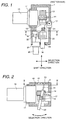
- Figs. 1 and 2 show a constitution example of a gearshift operating device for performing the gearshift operation of a normally contact-mesh type transmission of 5 forward speeds and 1 backward speed
- Fig. 1 is a transverse cross sectional view thereof
- Fig. 2 is a longitudinal cross sectional view thereof.
- a motor 10 for the shift operation installed in a housing 1 of the gearshift operating device amplifies the driving torque thereof by a planetary speed reducer 11, converts it to direct-acting power via a direct-acting conversion mechanism, for example, a rack 13 and a pinion 14, and acts force in the translation direction on a shift selection shaft 16 via a rotary coupling 15.
- the shift selection shaft 16 is attached to the housing 1 by bearings 24 for rotation and translation.
- a motor 20 for the selection operation installed to the housing 1 of the gearshift operating device amplifies the driving torque thereof via a planetary speed reducer 21 and acts rotary force on the shift selection shaft 16 via a gear 22 and a gear 23 operable axially.
- the shift selection shaft 16 is applied with action force in the translation direction by the motor 10 for the shift operation and applied with action force in the rotational direction by the motor 20 for the selection operation.
- the shift selection shaft 16 is provided with a shift finger 30 to be selectively joined to or dejoined from the shift fork shafts of the transmission and the shift finger 30, in the same way as with the shift selection shaft 16, is applied with action force in the translation direction by the motor 10 for the selection operation and applied with action force in the rotational direction by the motor 20 for the selection operation.
- the housing 1 includes a displacement sensor 17 for measuring the displacement of the shift selection shaft 16 in the translation direction and a rotational angle sensor 18 for measuring the rotational angle of the shift selection shaft 16.
- a follower arm 31 is provided integrally and passes through or is inserted into a guide slit 40 formed in a guide plate 2 provided on the top of the housing 1.
- the guide slit 40 is a slit formed in the guide plate 2 arranged on the top of the housing 1.
- a follower 33 is formed in a part of the follower arm 31 in contact with the guide slit.
- Fig. 3 shows a shape of the guide slit 40.
- the guide slit 40 has a plurality of parallel parts 41a to 41f and a plurality of slant parts 42a to 42d connected so as to come to a point from the plurality of parallel parts.
- a neutral point 43 the point where the slant parts 42a to 42d are focused will be referred to as a neutral point 43.
- the plurality of parallel parts 41a to 41f are parallel with the shift fork shafts.
- this direction will be referred to as a shift direction.
- the direction perpendicular to the shift direction shown in Fig. 3 will be referred to as a selection direction.
- the guide slit 40 guides the follower 33.
- the shift selection shaft 16 integral with the follower arm 31 and the shift finger 30 formed integrally with the shift selection shaft 16 are also guided by the shape of the guide slit 40.
- the follower 33 is smoothly guided by the guide slit 40, so that it is desirable that the section thereof is circular or both ends thereof in the shift direction are faces having a small curvature.
- Fig. 4 shows the relationship between the shift finger 30 and the shift fork shafts of the transmission.
- a general normally contact-mesh type transmission of 5 forward speeds and 1 backward speed has 3 shift fork shafts 51, 52, and 53.
- the respective shift fork shafts are operated axially, thus the gear is joined or dejoined.
- the shift finger 30 selects any of projections 54, 55, 56, 57, 58, and 59 of the shift fork shafts to join, thereby axially operates any of the shift fork shafts 51, 52, and 53 to join or dejoin the gear.
- the shift finger 30 joins to the projection 59 of the shift fork shaft 53 and moves in the first speed direction shown in the drawing, thus the first speed gear is joined.
- the shift finger 30 joins to the projection 58 of the shift fork shaft 53 and moves in the second speed direction shown in the drawing, thus the first speed gear is dejoined neutrally and then the second speed gear is joined.
- the follower arm 31 is on the opposite side of the shift finger 30 and the shift selection shaft 16, so that the follower arm 31 operates axially symmetrically to the shift finger 30.
- Figs. 5(a) to 5(e) are drawings showing the operations of the shift finger 30 and the shift fork shafts 51, 52, and 53 in time series when the transmission changes the speed from the second gear to the third gear.
- Fig. 6 is a drawing showing the position of the follower 33 corresponding to the timing shown in Fig. 5 in the guide slit.
- Figs. 7(a) to 7(e) are longitudinal cross sectional views of the gearshift operating device showing the inclination of the follower arm 31 corresponding Figs. 5 and 6.
- the dejoining operation for the second speed gear is performed by driving the motor for the shift operation, thereby applying driving force in the shift direction to the shift selection shaft 16.
- the shift selection shaft 16 is applied with thrust in the shift direction
- the shift finger 30 is also applied with thrust, joined to the projection 59 of the shift fork shaft 53, and pushes the shift fork shaft 53 in the gear dejoining direction.
- the shift fork shaft 53 is pushed by the shift finger 30 and as shown in Fig. 5(b), moved in the shift direction.
- the follower 33 moves on the parallel part 41b of the guide slit 40 in the shift direction.
- the position in the state is indicated by 33b shown in Fig. 6.
- the follower 33 moves on the slant part 42b shown in Fig. 6. At this time, the follower 33 is guided by the slant part 42b of the guide slit 40, so that regardless of application of driving force in the selection direction, the follower 33 moves along the slant part 42b.
- the shift finger 30 moves side by side in the direction of separation from the shift fork shaft 53, so that as shown in Fig. 5(c), the joint with the projection 59 of the shift fork shaft 53 comes off in a certain position. At this time, the second speed gear is dejoined already and the shift fork shaft 53 is almost in the neutral position.
- the shift fork shaft 53 can be dejoined from the shift finger 30 in the neutral position.
- the shift fork shaft 53 Even if the shift fork shaft 53 is dejoined from the shift finger 30 in a position different from the correct neutral position, the shift fork shaft 53, as long as no pressing force is acted on it from the shift finger 30, is not joined to the first speed gear or second speed gear and is set almost in the neutral position by the positioning mechanism arranged in the transmission.
- the shift finger 30, as shown in Fig. 5(d), is on the shift fork shaft 52 and when it goes straight on in the shift direction as it is, it joins to the projection 57, thereby can push the shift fork shaft 52. Further, the position of the follower arm is as shown in Fig. 7(d).
- the follower 33 When the follower 33 passes through the slant part 42b shown in Fig. 6 and reaches the position 33d (in the neighborhood of the neutral point 43), the follower 33 operates the motor 20 for the selection operation to move to the entrance of the slant part 42c (when changing to the first speed) shown in Fig. 3 or the slant part 42a (when changing to the fifth speed).
- the reason is that the force required for the shift operation is generally larger than the force required for the selection operation, so that the selection operation can also be performed by the motor for the shift operation.
- the motor 10 for the shift operation can complete the gearshift operation without stopping halfway. Therefore, the gearshift time is shortened and the energy required for acceleration and deceleration of the motor can be reduced.
- the motor 20 for the selection operation is operated to move the follower 33 to the entrance of the parallel part 41f (when changing to the fourth speed) or the slant part 42b (when changing to the reverse speed).
- the gearshift operation from the second gear is similarly performed. Namely, the motor 10 for the shift operation is operated first to generate driving force in the shift direction and the follower 33 is guided along the guide slit 40 and moved to the neutral point 43. At this time, the shift finger 30 joins to the projection of any of the shift fork shafts and operates the concerned shift fork shaft until the gear is dejoined.
- the motor 20 for the selection operation is operated in the neighborhood of the neutral point 43 to move the follower 33 to the entrance of a desired guide slit.
- the motor 10 for the shift operation is driven to guide and shift the follower 33 in the guide slit and to join a desired gear.
- the follower 33 When looking back at the aforementioned operation, regarding the gear dejoining operation, the follower 33 is guided obliquely or linearly by the guide slit 40, so that when operation force is just applied in the shift direction, even if no or small operation force is applied in the selection direction, the follower 33 can be moved to the neutral point 43.
- the force required for the selection operation is generally smaller than the force required for the shift operation, so that the motor for the shift operation can be used for the selection operation.
- the follower 33 is operated only at a minute distance in the selection direction from the state at the neutral point and moved to the entrance of any of the neighboring slits.
- the follower 33 when the follower 33 enters the slant part by the shift operation, the follower 33 is guided obliquely by the guide slit 40, so that only by the operation force in the shift direction, the follower 33 can be operated in the selection direction.
- the operation force in the selection direction is not necessary and the moving distance in the selection operation is very small, so that the actuator for the selection operation has force weaker than that of the actuator for the selection operation of a conventional gearshift operating device, thus a narrow use range can be applied.
- the follower 33 passes through the slant part and performs the gear dejoining operation, the follower 33 moves in the shift direction along the guide slit and simultaneously moves in the selection direction, so that the conventional operation of dejoining the gear first, stopping in the neutral position, and performing the selection operation next is not required.
- the actuator for the shift or selection operation is not required to start or stop and the gearshift operation is performed in the state of continuously driving the actuator for the shift operation, so that the gearshift operation time as a whole can be shortened greatly.
- the gearshift operating device is provided with a guide slit having a slant part, so that only by the driving force in the shift direction, the shift finger 30 can be driven in the selection direction. Therefore, the actuator for the selection operation just performs a minute positioning operation at the neutral point, thereby can select the gear.
- Fig. 9 is a drawing when Fig. 8 is viewed from the top.
- the follower 33 can be moved to the desired slit.
- Actuators 25 and 26 give pressing force to the follower arm 31 in the neighborhood of the neutral point 43.
- the actuators 25 and 26, for example, as shown in Fig. 10, has a mechanism that a link mechanism 28 is installed in a pull-type solenoid 27.
- a link mechanism 28 is installed in a pull-type solenoid 27.
- a pressing face 29 is pushed out to apply pressing force to the follower arm.
- the follower arm is applied with pressing force only in the neighborhood of the neutral point 43, so that the stroke of the actuators 25 and 26 may be short.
- the motor for the selection operation can be abolished, and the gearshift operating device can be miniaturized and lightened, and the cost can be decreased.
- the solenoid is highly responsive, so that the gear can be selected at high speed at the neutral point 43.
- the aforementioned embodiment indicates the structure using a planetary speed reducer for the speed reducer and a rack pinion for the motion conversion mechanism.
- the gearshift operating device of the present invention may be formed by using machine elements having the equal speed reduction or motion conversion function such as a worm gear or a spur gear for the speed reducer and a ball screw for the motion conversion mechanism.
- the aforementioned embodiment indicates an example that the guide slit 40 is formed on the top of the gearshift operating device.
- the guide slit may be arranged on the bottom of the gearshift operating device.
- the longitudinal cross sectional view of a configuration example thereof is shown in Fig. 14.
- the basic constituent parts are the same as those shown in Fig. 2.
- the guide plate 2 forming the guide slit 40 and the follower 33 guided by the guide slit 40 are arranged on the bottom of the shift selection shaft 16.
- the guide slit 40 is arranged in the same direction as that of the shift finger 30 and the shift selection shaft 16, so that the trace of the shift finger 30 and the trace of the follower 33 are similar to each other.
- the slit shape when the guide slit 40 is arranged on the bottom is line-symmetric to that when it is arranged on the top.
- a rotatory plate having a slit is shown in Fig. 11. This mechanism is arranged on the top or bottom of the guide plate 2.
- the corresponding guide slit 40 is indicated by a dotted line.
- a rotary plate 61 is installed for rotation on the housing 1, for example, by support portions 63a to 63d and rotated by an actuator 64 for the rotation operation.
- a slit 62 of the rotary plate 61 is a linear slit, for example, having a width through which the follower can pass at the center and both ends thereof are swollen.
- the rotary plate 61 limits the movable range of the follower arm together with the guide slit 40 to guide the follower 33.
- the actuator 64 for the rotation operation rotates the rotary plate 61 to decide the direction of the slit 62.
- the gear to be selected can be optionally decided.
- the load required for the rotation operation is lighter than the load required for the conventional selection operation, so that the actuator required for the conventional selection operation can be miniaturized and lightened and the whole gearshift operating device can be miniaturized and lightened.
- Each gate is opened by power supply and closed by stopping power supply. For example, when leading the follower 33 from the neutral point 43 to the slant part 42b, only the gate 35a arranged at the entrance of the slant part 42b is opened and the other gates 35b to 35d are closed.
- the basic operation method is the same as that of the aforementioned embodiments and the present invention can be applied.
- the present invention is to be applied to a normally contact-mesh type transmission of 4 forward speeds and 1 backward speed, the shift patterns shown in Figs. 13(c) to 13(e) may be used.
- the gearshift operating device of the present invention can be realized.
- the device has slant slits comprising slits parallel with the shift fork shafts as many as the number of gears for bringing them to the neutral point.
- the follower commonly goes obliquely or straight on toward the neutral point and the follower 33 is commonly operated minutely in the selection direction at the neutral point to select the gear.
- the shift and selection directions are different from those of the shift pattern of a regular FR car.
- the gearshift operating device of the present invention can be realized.
- a slit in a shape line-symmetric to each of the shift patterns shown in Figs. 13(a) to 13(f) is applied.
- the size of the gap between the projections and the shift finger is preferably equal to or wider than the width of the shift finger.
- the guide slit shown in Fig. 3 has linear slant parts.
- the slant parts preferably have a bent shape.
- the slant parts and parallel parts are preferably connected smoothly to each other.
- the follower is preferably provided with a roller.
- the shift finger 30 moves obliquely to enter between the projections 54 to 59, so that the corners of the shift finger 30 are preferably rounded so as to easily enter between the projections.
- the follower preferably has clearance for the guide slit so as to generate good hysteresis in the trace of the shift finger 30.
- the embodiments indicate the device for operating the transmission of a car. However, the device may be applied similarly to gearshift test equipment and gearshift feeling evaluation equipment.
- actuators for the operations in the shift direction and selection direction even if not only motors such as a DC motor, a DC brushless motor, and an AC motor but also a hydraulic actuator and an air pressure actuator are used, the same effects can be obtained.
- a guide slit having a plurality of slits parallel with the shift fork shafts and a plurality of slant slits concentrated to the.neutral point from them is provided, and the follower is operated in accordance with the guide slit, thus the shift finger can perform the selection operation and simultaneously the gear dejoining or gear joining operation, so that the time required for the gearshift operation can be shortened and the power consumption can be reduced.
- the actuator for the selection operation can be made compact and miniaturization and lightweight of the whole device can be realized.
- a gearshift operating device having a good loading property for performing a quick gearshift operation and actualizing comfortableness to ride in can be realized.
- the actuator for the selection operation can be omitted or miniaturized, so that the cost of the gearshift operating device can be reduced.
- the gearshift operation can be performed in a short time and the gearshift operating device can be miniaturized and lightened.
Landscapes
- Engineering & Computer Science (AREA)
- General Engineering & Computer Science (AREA)
- Mechanical Engineering (AREA)
- Gear-Shifting Mechanisms (AREA)
- Forklifts And Lifting Vehicles (AREA)
Abstract
Description
Claims (11)
- A gearshift operating device of a contact-mesh type transmission driving a shift selection shaft (16) in a first direction and a second direction different from said first direction to perform gear selection and gear joining and dejoining operations, wherein:said gear selection and gear joining and dejoining operations are performed by driving said shift selection shaft (16) in said first direction and simultaneously driving a second actuator (20), thereby driving said shift selection shaft (16) in said first direction and simultaneously driving it in said second direction.
- A gearshift operating device according to Claim 1, wherein said first direction is a direction along the axis of said shift selection shaft (16) and said second direction is a rotational direction round said shift selection shaft (16).
- A gearshift operating device according to Claim 2, further comprising a motor (10) for driving said shift selection shaft (16) in said first direction and a guide mechanism for converting motion of said shift selection shaft (16) in said first direction to motion in said second direction, wherein said shift selection shaft (16) is driven by said motor (10; 20) in said first and second directions.
- A gearshift operating device of a normally contact-mesh type transmission comprising a shift finger (30) selectively joining to or dejoining from shift fork shafts (51, 52, 53) of said normally contact-mesh type transmission, a shift selection shaft (16) including said shift finger (30), at least one electrically controllable driving means (10) for driving said shift selection shaft (16) in the direction (the shift direction) parallel with said shift fork shafts (51, 52, 53), at least one electrically controllable driving means (20) for driving said shift selection shaft (16) in the direction (the selection direction) perpendicular to said shift fork shafts (51, 52, 53), a follower (33) formed integrally with said shift selection shaft (16), and a guide slit (40) joined to said follower (33) to guide the operation of said shift selection shaft (16), wherein:said guide slit (40) has a plurality of parallel parts (41a-e) parallel with said shift fork shafts (51, 52, 53) and a plurality of slant parts (42a-d) connected so as to come to a point (43) at the neutral position from said plurality of parallel parts (41a-e).
- A gearshift operating device of a normally contact-mesh type transmission comprising a shift finger (30) selectively joining to or dejoining from shift fork shafts (51, 52, 53) of said normally contact-mesh type transmission, a shift selection shaft (16) including said shift finger (30), at least one electrically controllable driving means (10) for driving said shift selection shaft (16) in the direction (the shift direction) parallel with said shift fork shafts (51, 52, 53), at least one electrically controllable driving means (20) for pressing said shift selection shaft (20) in the direction (the selection direction) perpendicular to said shift fork shafts (51, 52, 53), a follower (33) formed integrally with said shift selection shaft (16), and a guide slit (40) joined to said follower (33) to guide the operation of said shift selection shaft (16), wherein:said guide slit (40) has a plurality of parallel parts (41a-e) parallel with said shift fork shafts (51, 52, 53) and a plurality of slant parts (42a-d) connected so as to come to a point (43) at the neutral position from said plurality of parallel parts (41a-e).
- A gearshift operating device of a normally contact-mesh type transmission comprising a shift finger (30) selectively joining to or dejoining from shift fork shafts (51, 52, 53) of said normally contact-mesh type transmission, a shift selection shaft (16) including said shift finger (30), at least one electrically controllable driving means (10) for operating said shift selection shaft (16) in the direction (the shift direction) parallel with said shift fork shafts (51, 52, 53), a follower (33) formed integrally with said shift selection shaft (16), and a guide slit (40) joined to said follower (33) to guide the operation of said shift selection shaft (16), wherein:said guide slit (40) has a plurality of parallel parts (41a-e) parallel with said shift fork shafts (51, 52, 53) and a plurality of slant parts (42a-d) connected so as to come to a point (43) at the neutral position from said plurality of parallel parts (41a-e) and each slit arranged in said guide slit (40) has an electrically switched gate (35a-d).
- A gearshift operating device according to any one of Claims 4 to 6, wherein said parallel parts (41a-e) of said guide slit (40) and said slant parts (42a-d) of said guide slit (40) are smooth curved slits continuously connected.
- A gearshift operating device according to any one of Claims 4 to 7, wherein said follower (33) has a curved section.
- A gearshift operating device according to any one of Claims 4 to 8, wherein said follower (33) has a roller.
- A gearshift operating device according to any one of Claims 4 to 9, wherein clearance of the joint between said shift finger (30) and said shift fork shafts (51, 52, 53) is almost equal to or wider than the width of said shift finger (30).
- A gearshift operating device according to any one of Claims 4 to 10, wherein the width of said follower (33) has some clearance for the width of said guide slit (40).
Applications Claiming Priority (2)
| Application Number | Priority Date | Filing Date | Title |
|---|---|---|---|
| JP2003034492 | 2003-02-13 | ||
| JP2003034492A JP4244650B2 (en) | 2003-02-13 | 2003-02-13 | Shifting operation device |
Publications (2)
| Publication Number | Publication Date |
|---|---|
| EP1447595A2 true EP1447595A2 (en) | 2004-08-18 |
| EP1447595A3 EP1447595A3 (en) | 2005-07-20 |
Family
ID=32677596
Family Applications (1)
| Application Number | Title | Priority Date | Filing Date |
|---|---|---|---|
| EP03028635A Withdrawn EP1447595A3 (en) | 2003-02-13 | 2003-12-15 | Gearshift operating device |
Country Status (3)
| Country | Link |
|---|---|
| US (1) | US7370551B2 (en) |
| EP (1) | EP1447595A3 (en) |
| JP (1) | JP4244650B2 (en) |
Cited By (2)
| Publication number | Priority date | Publication date | Assignee | Title |
|---|---|---|---|---|
| KR101592818B1 (en) | 2015-04-10 | 2016-02-15 | 현대자동차주식회사 | Shifting gear device for vehicle |
| WO2018233223A1 (en) * | 2017-06-20 | 2018-12-27 | 北理慧动(常熟)车辆科技有限公司 | Horizontal pure electric selection and shifting mechanism of AMT control system |
Families Citing this family (4)
| Publication number | Priority date | Publication date | Assignee | Title |
|---|---|---|---|---|
| JP4807123B2 (en) * | 2006-03-27 | 2011-11-02 | トヨタ自動車株式会社 | Transmission control device |
| JP4839245B2 (en) * | 2007-02-23 | 2011-12-21 | 株式会社イケヤフォ−ミュラ | Shifting operation device |
| KR101091610B1 (en) * | 2009-10-29 | 2011-12-13 | 한국과학기술연구원 | Multiple Choice Micro Manipulators |
| CN106763724A (en) * | 2017-01-19 | 2017-05-31 | 西华大学 | The optimal Shift Strategy system of many performance synthesises of automobile geared automatic transmission |
Family Cites Families (10)
| Publication number | Priority date | Publication date | Assignee | Title |
|---|---|---|---|---|
| GB1162010A (en) * | 1966-11-08 | 1969-08-20 | Ford Motor Co | Motor Vehicle Transmissions |
| US4817468A (en) * | 1987-06-18 | 1989-04-04 | Ap Aero, Inc | Electric shift apparatus for manual transmission |
| US5035113A (en) * | 1988-05-19 | 1991-07-30 | Csepel Autogyar | Electropneumatic remote control for shifting the mechanical transmission of a motor vehicle |
| US4873881A (en) * | 1989-01-06 | 1989-10-17 | Eaton Corporation | Electrically actuated x-y shifting mechanism |
| DE19822666B4 (en) * | 1997-05-30 | 2015-06-18 | Schaeffler Technologies AG & Co. KG | Device for actuating a pivotable about an axis and displaceable along the axis of the switching shaft of a gearbox |
| JPH11270672A (en) * | 1997-12-18 | 1999-10-05 | Aft Atlas Fahrzeugtechnik Gmbh | Operating device |
| US6227067B1 (en) * | 1999-10-29 | 2001-05-08 | Eaton Corporation | Independent motor control for X-Y shifter |
| JP3941906B2 (en) * | 1999-11-17 | 2007-07-11 | 三菱電機株式会社 | Control device for synchronous mesh automatic transmission |
| US6301537B1 (en) * | 2000-06-05 | 2001-10-09 | Eaton Corporation | Adaptive calibration of X-Y position sensor |
| DE10345906A1 (en) * | 2002-10-09 | 2004-04-22 | Luk Lamellen Und Kupplungsbau Beteiligungs Kg | Method of controlling motor vehicle gearbox involves controlling engine clutch and gearbox dependent on vehicle function |
-
2003
- 2003-02-13 JP JP2003034492A patent/JP4244650B2/en not_active Expired - Fee Related
- 2003-12-15 EP EP03028635A patent/EP1447595A3/en not_active Withdrawn
- 2003-12-24 US US10/743,748 patent/US7370551B2/en not_active Expired - Fee Related
Cited By (2)
| Publication number | Priority date | Publication date | Assignee | Title |
|---|---|---|---|---|
| KR101592818B1 (en) | 2015-04-10 | 2016-02-15 | 현대자동차주식회사 | Shifting gear device for vehicle |
| WO2018233223A1 (en) * | 2017-06-20 | 2018-12-27 | 北理慧动(常熟)车辆科技有限公司 | Horizontal pure electric selection and shifting mechanism of AMT control system |
Also Published As
| Publication number | Publication date |
|---|---|
| JP4244650B2 (en) | 2009-03-25 |
| US20040159171A1 (en) | 2004-08-19 |
| JP2004245293A (en) | 2004-09-02 |
| EP1447595A3 (en) | 2005-07-20 |
| US7370551B2 (en) | 2008-05-13 |
Similar Documents
| Publication | Publication Date | Title |
|---|---|---|
| US7762154B2 (en) | Synchromesh automatic transmission | |
| US6389919B1 (en) | Compact gearbox | |
| RU2374533C1 (en) | Transmission | |
| EP2668421B1 (en) | Gear change actuator | |
| DE112009005334T5 (en) | SHIFT-MANAGEMENT CONTROL DEVICE OF A VEHICLE | |
| US7007566B2 (en) | Actuator for a motor vehicle transmission | |
| EP1156240A1 (en) | Electric drive device for transmission | |
| KR20210006035A (en) | Shifting actuator for transmission | |
| US5901608A (en) | Automatic speed-change apparatus for a gear transmission | |
| WO2004045885A1 (en) | Electronic gearshift apparatus of sub gearshift for 4 wheel drive vehicle | |
| EP1447595A2 (en) | Gearshift operating device | |
| US5970811A (en) | Automatic speed-change apparatus for a gear transmission | |
| GB2325967A (en) | Apparatus for operating a selector shaft of a gearbox | |
| JP4252905B2 (en) | transmission | |
| EP0928911A1 (en) | Automatic speed-change apparatus for a gear transmission | |
| JP2000035127A (en) | Electric Select-Shift System for Synchronous Meshing Gearbox | |
| RU2374532C1 (en) | Transmission | |
| EP0652391A1 (en) | Preselect shift strategy using stored energy | |
| EP0926406A2 (en) | Shift device for a manual transmission | |
| WO2009119819A1 (en) | Range selector | |
| GB2325714A (en) | Device for operating a selector shaft of a shift transmission | |
| KR101795734B1 (en) | Gear actuator of Dual clutch transmission | |
| CN1122422A (en) | Mehrgang-stufengetriebe a stepper motor vehicle transmission | |
| JP4957708B2 (en) | Shifting device for automatic transmission | |
| KR100558299B1 (en) | Vehicle shift control |
Legal Events
| Date | Code | Title | Description |
|---|---|---|---|
| PUAI | Public reference made under article 153(3) epc to a published international application that has entered the european phase |
Free format text: ORIGINAL CODE: 0009012 |
|
| AK | Designated contracting states |
Kind code of ref document: A2 Designated state(s): AT BE BG CH CY CZ DE DK EE ES FI FR GB GR HU IE IT LI LU MC NL PT RO SE SI SK TR |
|
| AX | Request for extension of the european patent |
Extension state: AL LT LV MK |
|
| PUAL | Search report despatched |
Free format text: ORIGINAL CODE: 0009013 |
|
| AK | Designated contracting states |
Kind code of ref document: A3 Designated state(s): AT BE BG CH CY CZ DE DK EE ES FI FR GB GR HU IE IT LI LU MC NL PT RO SE SI SK TR |
|
| AX | Request for extension of the european patent |
Extension state: AL LT LV MK |
|
| RIC1 | Information provided on ipc code assigned before grant |
Ipc: 7F 16H 61/32 B Ipc: 7F 16H 61/08 B Ipc: 7F 16H 59/04 A |
|
| 17P | Request for examination filed |
Effective date: 20051111 |
|
| AKX | Designation fees paid |
Designated state(s): DE |
|
| STAA | Information on the status of an ep patent application or granted ep patent |
Free format text: STATUS: THE APPLICATION IS DEEMED TO BE WITHDRAWN |
|
| 18D | Application deemed to be withdrawn |
Effective date: 20060905 |