EP1447257A2 - Mount structure for fuel tank - Google Patents
Mount structure for fuel tank Download PDFInfo
- Publication number
- EP1447257A2 EP1447257A2 EP04002564A EP04002564A EP1447257A2 EP 1447257 A2 EP1447257 A2 EP 1447257A2 EP 04002564 A EP04002564 A EP 04002564A EP 04002564 A EP04002564 A EP 04002564A EP 1447257 A2 EP1447257 A2 EP 1447257A2
- Authority
- EP
- European Patent Office
- Prior art keywords
- fuel tank
- frame
- tank
- mount structure
- vehicle
- Prior art date
- Legal status (The legal status is an assumption and is not a legal conclusion. Google has not performed a legal analysis and makes no representation as to the accuracy of the status listed.)
- Granted
Links
Images


Classifications
-
- B—PERFORMING OPERATIONS; TRANSPORTING
- B60—VEHICLES IN GENERAL
- B60K—ARRANGEMENT OR MOUNTING OF PROPULSION UNITS OR OF TRANSMISSIONS IN VEHICLES; ARRANGEMENT OR MOUNTING OF PLURAL DIVERSE PRIME-MOVERS IN VEHICLES; AUXILIARY DRIVES FOR VEHICLES; INSTRUMENTATION OR DASHBOARDS FOR VEHICLES; ARRANGEMENTS IN CONNECTION WITH COOLING, AIR INTAKE, GAS EXHAUST OR FUEL SUPPLY OF PROPULSION UNITS IN VEHICLES
- B60K15/00—Arrangement in connection with fuel supply of combustion engines or other fuel consuming energy converters, e.g. fuel cells; Mounting or construction of fuel tanks
- B60K15/03—Fuel tanks
- B60K15/063—Arrangement of tanks
- B60K15/067—Mounting of tanks
- B60K15/07—Mounting of tanks of gas tanks
-
- B—PERFORMING OPERATIONS; TRANSPORTING
- B60—VEHICLES IN GENERAL
- B60K—ARRANGEMENT OR MOUNTING OF PROPULSION UNITS OR OF TRANSMISSIONS IN VEHICLES; ARRANGEMENT OR MOUNTING OF PLURAL DIVERSE PRIME-MOVERS IN VEHICLES; AUXILIARY DRIVES FOR VEHICLES; INSTRUMENTATION OR DASHBOARDS FOR VEHICLES; ARRANGEMENTS IN CONNECTION WITH COOLING, AIR INTAKE, GAS EXHAUST OR FUEL SUPPLY OF PROPULSION UNITS IN VEHICLES
- B60K15/00—Arrangement in connection with fuel supply of combustion engines or other fuel consuming energy converters, e.g. fuel cells; Mounting or construction of fuel tanks
- B60K15/03—Fuel tanks
- B60K15/063—Arrangement of tanks
- B60K2015/0638—Arrangement of tanks the fuel tank is arranged in the rear of the vehicle
Definitions
- the present invention relates to a fuel tank mount structure for allowing a fuel tank to be efficiently located below a floor of a rear area of a vehicle body.
- a vehicle body structure wherein a fuel tank mounting structure is located below a floor of a vehicle body through a tank mount structure (refer to Japanese Patent Application Laid-Open
- the present invention contemplates to provide a fuel tank mount structure to allow a high pressure fuel tank to be mounted below a floor of the rear of a vehicle body, wherein a front edge portion of a rear suspension member disposed in a rear area of the high pressure fuel tank is formed along a rear profile of the high pressure fuel tank.
- a vehicle body rear section 10, to which a fuel tank mount structure of a first embodiment is applied, is configured in a structure as shown in FIG. 1.
- Rear side members 11, 11 extending fore and aft direction of a vehicle are disposed beneath a floor (not shown) of the vehicle, and a first tank frame 12 is disposed below the rear side members 11, 11.
- the first tank frame 12 supports a fuel tank 24, being filled with such as a hydrogen gas.
- a rear suspension member 13 is disposed in a rear area of the first tank frame 12.
- a rear cross member 14 is disposed in a rear side of the suspension member 13.
- the rear side members 11, 11 are disposed beneath a floor panel 43, and disposed on the both ends in the vehicle widthwise direction.
- the first tank frame 12 located below front portions of the rear side members 11, the first tank frame 12 is disposed.
- the first tank frame 12 is comprised of a front cross frame 17 laterally extending on a front side, side frames 18, 18 extending rearward of the vehicle at both left and right ends of the center cross member 17, a center cross member 19 fastened to central areas of the side frames 18, 18 in respect of the fore and aft direction of the vehicle, and a rear cross member 20 fastened to rear ends of the side frames 18, 18.
- the front cross frame 17 extends in the vehicle widthwise direction to allow the left and right rear side members 11, 11 to be bridged.
- the side frames 18, 18 extend rearward of the vehicle from the front cross frame 17.
- the side frames 18 extend rearward of the vehicle and bend inward in the vehicle widthwise direction at joints 22, 22 of the center cross frame 19, and as shown in FIG. 2, rear end portions 23, 23 of the side frames 18, 18 are bent upward and coupled to the rear cross frame 20.
- the rear suspension member 13 is disposed rearward of the vehicle and above the first tank frame 12 and is formed in a double cross shape as shown in FIG. 1.
- the rear suspension member 13 is comprised of a front suspension cross member 27 disposed on a forward area of the rear suspension member 13 and extending in the vehicle widthwise direction, a rear suspension cross member 28 disposed rearward of the front suspension cross member 27 on a rear side of the vehicle and extending in the vehicle widthwise direction, and suspension side members 29, 29 connecting the front suspension cross member 27 and the rear suspension cross member 28. Both the left and right ends of the front suspension cross member 27 and the rear suspension cross member 28 are fastened to lower surfaces of the rear side members 11, respectively.
- the front suspension cross member 27 is comprised of a body portion 30 formed in a central area in the vehicle widthwise direction, and a pair of extensions 31, 31 extending forward of the vehicle at left and right ends of the body portion 30, the body portion 30 and the extensions 31 being formed along a rear profile of the fuel tank 24.
- the rear cross member 14 connects the rear side members 11, 11 to allow these components 11, 11 to be bridged in the vehicle widthwise direction at connecting portions 32, 32, and tank mount brackets 33, 33 extend from the connecting portions 32, 32 to front side of the vehicle.
- the tank mount brackets 33, 33 are mounted in the same height as the rear cross member 14. Fastening portions 35, 35 of both left and right ends of the rear cross member 20 of the tank frame 12 are mounted below distal ends 34, 34 of the tank mount brackets 33, 33. Also, front ends of the tank mount brackets 33, 33 are mounted to lower surfaces of the cross member 50 through which the rear side members 11, 11 are bridged.
- the fastening portions 35, 35 are disposed between the front suspension cross member 27 and the rear suspension cross member 28.
- the rear suspension member 13 is placed between the side frames 18, 18 of the first tank frame 12 and the tank mount bracket 33.
- rear suspension brackets 37 serving as a rear suspension fastening segment protrudes downwardly.
- the side frames 18, 18 are provided below the suspension brackets 37, 37 as shown in FIG. 1.
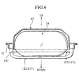
- both left and right sides of the front cross frame 17 formed in approximately a trapezoid shape. That is, the front cross frame 17 of the first tank frame is comprised of both left and right end portions 40, 40 fastened to the lower surfaces of the rear side members 11, respectively, inclined portions 41, 41 extending from both the left and right end portions 40, 40 and sloping downwardly of the vehicle toward a center in the vehicle widthwise direction, respectively, and a bottom portion 42 connected to terminal ends of the left and right inclined portions 41, 41, respectively. Also, as shown in FIG. 1, a floor panel 43 of the vehicle body is configured to form along an upper profile of the fuel tank 24.
- the fuel tank mount structure 24 of the first embodiment having the structure set forth above has various advantages listed below.
- the fuel tank 24 is located in a space defined by the rear suspension member 13 and the rear side members 11, 11, and the front suspension cross member 27 forming a front edge portion of the rear suspension member 13 is formed in a shape contoured along the rear profile of the fuel tank 24, and therefore a gap between the fuel tank 24 and the rear suspension member 13 can be minimized, resulting in a capability of improving a space efficiency in an area below the floor panel 43.
- tank mount brackets 33, 33 are mounted to the joint portions 32, 32 between the rear side members 11, 11 and the rear cross member 14, an improved rigidity of the vehicle body can be obtained. And therefore, it is possible for the connecting portions 32, 32 to be restricted from being deformed due to impact loads applied to the rear of the vehicle.
- the first tank frame 12 having the front cross frame 17 is configured to extend upward of the vehicle and outward in the vehicle widthwise direction in a gradual slope toward the rear side members 11, 11, such a structure contributes to an increase in a rigidity of the vehicle body, while enabling the vehicle body from being deformed due to impact loads, such as sidewise collisions, applied to a side of the vehicle.
- the fastening portions 35, 35 being located at the rear side of the first tank frame 12 are disposed between the front suspension cross member 27 and the rear suspension cross member 28 of the rear suspension member 13, the first tank frame 12 for the fuel tank 24 can be fastened to the vehicle body while permitting the rear surface of the fuel tank 24 to be placed near the rear suspension member 13 as close as possible. Also, according to this structure, it is possible to alleviate an impact load applied to the vehicle from the longitudinal direction of the vehicle.
- the side frames 18 connecting the fore and aft portions of the first tank frame 12 are located below the rear suspension brackets 37, 37 that serve as rear suspension fastening portions of the rear suspension member 13, the side frames 18, 18 have no obstruction for operation the suspension 38, and therefore the fuel tank 24 and the suspension 38 can be placed in a high space efficiency.
- the presence of the rear terminal portions of the side frames 18 connected to the rear cross frame 20 while connecting the both ends of the rear cross frame 20 to the tank mount brackets 33 provides an improved degree of freedom in mounting to allow the first tank frame 12 to be fastened to a highly rigidity area of the vehicle body, enabling the rear end portions of the first tank frame 12 to have an increased mount span in the vehicle widthwise direction while improving a mount rigidity of the first tank frame 12.
- FIG. 4 is a bottom view of a vehicle body rear section 110, to which a fuel tank mount structure of a second embodiment is applied, as viewed from the bottom.
- the rear side members 11, 11 extending fore and aft direction of the vehicle are disposed on both sides of the vehicle body in the widthwise direction thereof.
- a rear suspension member 113 is placed in a rear area of the fuel tank 24, and a second tank frame 112 is placed so as to straddle over the fore and aft areas of the fuel tank 24.
- the rear suspension member 113 is unitarily comprised of a front suspension cross member 127 positioned in the front of the rear suspension member 113 and extending in the vehicle widthwise direction, a rear suspension cross member 128 positioned rearward of the front suspension cross member 127 and extending in the vehicle widthwise direction, side suspension cross members 150, 150 connecting both left and right ends of the front suspension cross member 127 and the rear suspension cross member 128, and suspension side members 129, 129 disposed inside the side suspension cross members 150, 150, respectively, in the vehicle widthwise direction and extending in the fore and aft direction of the vehicle while connected to the front suspension cross member 127 and the rear suspension cross member 128, respectively.
- the front suspension cross member 127 and the rear suspension cross member 128 are placed so as to allow the left and right rear side members 11, 11 to be bridged.
- the front suspension cross member 127 is unitarily further comprised of a body portion 130 linearly formed in a central area in the vehicle widthwise direction, and extensions 131, 131 extending obliquely forward of the vehicle from both left and right ends of the body portion 130.
- the body portion 130 and the extensions 131, 131 being formed in configuration contoured along the rear profile of the fuel tank 24.
- the side suspension cross members 150 are disposed in the fore and aft direction of the vehicle along the lower surfaces of the rear side members 11.
- the second tank frame 12 is formed in a substantially U-shape in a plan view and comprised of a front cross frame 117 located in a front side, and side frames 151, 151 extending from both left and right ends of the front cross frame 117 toward the both left and right ends of the front suspension cross member 127.
- the both left and right ends of the rear suspension member 113, the front cross frame 117 and the side frames 151 are mounted to the rear side members 11 by means of fastening units 152.
- rear ends of the side frames 151 are integrally connected to the front ends of the side suspension cross members 150 and the both left and right ends of the side suspension cross members 127 by means of fastening units 152.
- the second tank frame 112 is integrally formed with the rear suspension member 113 (into a module structure).
- the side frames 151 forming the second tank frame 112 are linearly and integrally connected to the side suspension cross members 150 of the rear suspension member 113 by means of the fastening units 152 to form a module structure. Also, the side frames 151 are placed in substantially the same height as that of the side suspension cross members 150.
- the both left and right ends of the front cross frame 117 forming the second tank frame 112 are mounted to lower ends of the fastening units 152 located beneath the rear side members 11. That is, the fastening units 152 are located beneath the rear side members 11, and the front cross frame 117 extends from the lower ends of the fastening units 152 obliquely downward and gradually curved inward in the vehicle widthwise direction. Also, on the rear side of the front cross frame 117, the rear suspension member 113 is linearly connected to the left and right rear side members 11, 11.
- the fuel tank mount structure of the second embodiment set forth above has various advantages described below.
- the rear suspension member 113 can be placed closer to the fuel tank 24 without wasteful space between the rear suspension member 113 and the fuel tank 24 while achieving reduction in the number of component parts, resulting in a capability of reducing cost and providing a light weight while improving a production efficiency.
- the second tank frame 112 and the rear suspension member 113 are located by connecting the left and right rear side members 11, 11 with respect to one another, a strength of the vehicle body can be improved and, especially, the vehicle body is able to have a rigidity against loads, such as sidewise collisions, to be applied to the side of the vehicle body.
- the side frames 151, 151 of the second tank frame 112 are disposed in the fore and aft direction of the vehicle body along the lower surfaces of the rear side members 11, 11 and both ends of the front cross frame 117 and the front suspension cross member 127 are connected to one another by means of the fastening units 152 in a bridged form, it becomes possible for the vehicle body to have an increased rigidity that resists against loads, such as rear collisions, applied to the rear of the vehicle.
Landscapes
- Engineering & Computer Science (AREA)
- Life Sciences & Earth Sciences (AREA)
- Sustainable Development (AREA)
- Sustainable Energy (AREA)
- Chemical & Material Sciences (AREA)
- Combustion & Propulsion (AREA)
- Transportation (AREA)
- Mechanical Engineering (AREA)
- Body Structure For Vehicles (AREA)
- Cooling, Air Intake And Gas Exhaust, And Fuel Tank Arrangements In Propulsion Units (AREA)
Abstract
Description
Claims (9)
- A fuel tank mount structure to allow a fuel tank to be placed in a lower area of a floor located in a rear area (10) of a vehicle body, comprising
a rear suspension member (13, 113) disposed rearward of the fuel tank (24) and having a front edge portion formed in a configuration contoured along a rear profile of the fuel tank. - The fuel tank mount structure according to claim 1, wherein the rear suspension member further comprises a front suspension cross member (27) formed at the front edge portion so as to extend in a vehicle widthwise direction, and a rear suspension cross member (28) disposed rearward of the front suspension cross member so as to extend in the vehicle widthwise direction,
and wherein a rear side of a first tank frame (12) for holding the fuel tank is mounted to the vehicle body at an area between the front suspension cross member and the rear suspension cross member. - The fuel tank mount structure according to claims 1 or 2, wherein left and right both sides of a front portion of the first tank frame 1 are inclined upward of a vehicle and outward in the vehicle widthwise direction.
- The fuel tank mount structure according to any one of claims 1 to 3, wherein tank mount brackets (33, 33) are disposed at connecting portions (32, 32) connecting a rear side members (11, 11) being placed on left and right sides of the vehicle body in the vehicle widthwise direction and a rear cross member (14), and both ends of a rear cross frame (20) forming a rear end of the first tank frame are fastened to the tank mount brackets.
- The fuel tank mount structure according to any one of preceding claims 1 to 3, wherein side frames (18, 18) connecting the front cross frame and the rear cross frame of the first tank frame are disposed downward of rear suspension brackets (37) of the rear suspension member.
- The fuel tank mount structure according to claim 5, wherein the side frames is configured t o bent inwardly in the vehicle widthwise direction as the side frames extend rearwardly, and rear ends of the side frames are fastened to the rear cross frame being located in a rear end of the first tank frame, at positions inward of both ends thereof in the vehicle widthwise direction, with the both ends of the rear cross frame being fastened to the vehicle body.
- The fuel tank mount structure according to claim 1, wherein a second tank frame (112) for holding the fuel tank is unitarily formed with the rear suspension member (113).
- The fuel tank mount structure according to claim 7, wherein the second tank frame is positioned forward of the fuel tank,
and wherein the second tank frame and the rear suspension member are connected to the rear side members one another. - The fuel tank mount structure according to claims 7 or 8, wherein the second tank frame includes side frames (151, 151) extending forward of both left and right ends of the rear side member along the rear side members.
Applications Claiming Priority (4)
| Application Number | Priority Date | Filing Date | Title |
|---|---|---|---|
| JP2003033943 | 2003-02-12 | ||
| JP2003033943 | 2003-02-12 | ||
| JP2003309146A JP4075744B2 (en) | 2003-02-12 | 2003-09-01 | Fuel tank mounting structure |
| JP2003309146 | 2003-09-01 |
Publications (3)
| Publication Number | Publication Date |
|---|---|
| EP1447257A2 true EP1447257A2 (en) | 2004-08-18 |
| EP1447257A3 EP1447257A3 (en) | 2004-12-01 |
| EP1447257B1 EP1447257B1 (en) | 2007-04-25 |
Family
ID=32684283
Family Applications (1)
| Application Number | Title | Priority Date | Filing Date |
|---|---|---|---|
| EP04002564A Expired - Lifetime EP1447257B1 (en) | 2003-02-12 | 2004-02-05 | A rear area of a vehicle body |
Country Status (4)
| Country | Link |
|---|---|
| US (2) | US7063355B2 (en) |
| EP (1) | EP1447257B1 (en) |
| JP (1) | JP4075744B2 (en) |
| DE (1) | DE602004006032T2 (en) |
Cited By (1)
| Publication number | Priority date | Publication date | Assignee | Title |
|---|---|---|---|---|
| EP2133259A1 (en) * | 2008-06-11 | 2009-12-16 | Nissan Motor Company Limited | Tank-carrying vehicle rear body structure |
Families Citing this family (35)
| Publication number | Priority date | Publication date | Assignee | Title |
|---|---|---|---|---|
| US7264277B2 (en) * | 2004-01-22 | 2007-09-04 | Honda Motor Co., Ltd. | Gaseous fuel vehicle rear structure |
| KR100599565B1 (en) * | 2004-07-20 | 2006-07-13 | 현대모비스 주식회사 | Torsion beam type suspension device with variable shape |
| US7513329B2 (en) * | 2005-03-02 | 2009-04-07 | Honda Motor Co., Ltd. | Vehicle rear body structure |
| US7699346B2 (en) * | 2005-03-23 | 2010-04-20 | Chrysler Group Llc | Force redistributing system for a vehicle in the event of a rear impact |
| US7641017B2 (en) * | 2005-06-02 | 2010-01-05 | Honda Motor Co., Ltd. | Fuel cell vehicle |
| US7744127B2 (en) * | 2006-09-29 | 2010-06-29 | Gm Global Technology Operations, Inc. | Fuel tank mount |
| JP4286884B2 (en) * | 2007-06-28 | 2009-07-01 | 本田技研工業株式会社 | Auto body structure |
| DE102007047037A1 (en) * | 2007-10-01 | 2009-04-02 | Volkswagen Ag | Motor vehicle body has two rear side longitudinal supports arranged oppositely in rear end, where rear side longitudinal supports, supporting frame and cross beams are provided with fitting position |
| JP4349457B2 (en) * | 2007-10-23 | 2009-10-21 | トヨタ自動車株式会社 | High-pressure tank mounted vehicle and tank assembly |
| JP5125769B2 (en) * | 2008-05-30 | 2013-01-23 | マツダ株式会社 | Electric vehicle body structure |
| JP4500867B2 (en) * | 2008-07-07 | 2010-07-14 | 本田技研工業株式会社 | Car body rear structure |
| US8465057B2 (en) * | 2008-08-27 | 2013-06-18 | GM Global Technology Operations LLC | Rear integration of a suspension system and fuel tanks in fuel cell vehicles |
| JP5168214B2 (en) * | 2009-04-08 | 2013-03-21 | トヨタ自動車株式会社 | Car body rear structure |
| EP2439128B1 (en) * | 2009-06-05 | 2016-11-30 | Toyota Jidosha Kabushiki Kaisha | Vehicle |
| DE102009042513A1 (en) * | 2009-09-22 | 2011-03-24 | GM Global Technology Operations, Inc., Detroit | Vehicle with energy storage area |
| US7913788B1 (en) * | 2010-02-09 | 2011-03-29 | Gm Global Technology Operations, Llc | Integrated energy storage and rear suspension assembly |
| DE102010011268A1 (en) * | 2010-03-13 | 2011-09-15 | Bayerische Motoren Werke Aktiengesellschaft | Motor vehicle has fuel tank, which is arranged at underside of floor assembly, where floor assembly comprises bench or step-shaped cross section portion in region of rear seat or rear seats |
| US20140021711A1 (en) * | 2010-05-03 | 2014-01-23 | Shem, Llc | Heavy Duty Truck Chassis Having Rear Mounted Fuel Tank |
| US8480131B2 (en) * | 2010-09-30 | 2013-07-09 | GM Global Technology Operations LLC | Integrated pressure vessels for vehicular applications |
| US9114930B2 (en) * | 2011-03-07 | 2015-08-25 | Casella Waste Systems, Inc. | Compressed natural gas vehicle apparatus and method |
| JP5365660B2 (en) * | 2011-04-20 | 2013-12-11 | トヨタ自動車株式会社 | Vehicle lower structure |
| JP2012254782A (en) * | 2011-05-17 | 2012-12-27 | Nissan Motor Co Ltd | Non-contact charger mounting structure |
| JP2012257443A (en) * | 2011-05-17 | 2012-12-27 | Nissan Motor Co Ltd | Non-contact charger mounting structure |
| WO2013059679A1 (en) | 2011-10-21 | 2013-04-25 | Fisker Automotive, Inc. | Rear-wheel drive, plug-in hybrid electric vehicle modular subframe assembly and method |
| US9162565B2 (en) | 2012-08-31 | 2015-10-20 | Caterpillar Inc. | Liquid natural gas storage tank mounting system |
| JP2014148227A (en) * | 2013-01-31 | 2014-08-21 | Yachiyo Industry Co Ltd | Fitting structure of fuel tank to vehicle body |
| US9579969B2 (en) | 2014-07-25 | 2017-02-28 | Oshkosh Corporation | Refuse vehicle having tailgate-mounted CNG tanks |
| US10081243B2 (en) | 2015-05-03 | 2018-09-25 | Natural Gas Fuel Systems, Inc. | Apparatuses for mounting tanks to vehicles and related methods |
| JP6432541B2 (en) * | 2016-02-18 | 2018-12-05 | トヨタ自動車株式会社 | Vehicle with gas tank |
| JP6439986B2 (en) * | 2016-02-22 | 2018-12-19 | トヨタ自動車株式会社 | Fuel cell vehicle |
| US11042745B2 (en) | 2018-04-23 | 2021-06-22 | Oshkosh Corporation | Refuse vehicle control system |
| CN108773265A (en) * | 2018-06-12 | 2018-11-09 | 芜湖爱丽机电科技有限公司 | Mounting structure for new-energy automobile air accumulator |
| CN108544920A (en) * | 2018-06-12 | 2018-09-18 | 芜湖爱丽机电科技有限公司 | A kind of new-energy automobile air accumulator arrangement |
| CN108790803A (en) * | 2018-06-12 | 2018-11-13 | 芜湖爱丽机电科技有限公司 | New-energy automobile air accumulator arrangement |
| JP7316507B2 (en) * | 2019-05-16 | 2023-07-28 | マツダ株式会社 | Rear structure of electric vehicle |
Family Cites Families (43)
| Publication number | Priority date | Publication date | Assignee | Title |
|---|---|---|---|---|
| US1611906A (en) * | 1925-05-27 | 1926-12-28 | Int Motor Co | Tank support |
| JPS55153159A (en) * | 1979-05-15 | 1980-11-28 | Sony Corp | Digital signal recorder |
| JPS58137329A (en) * | 1982-02-10 | 1983-08-15 | Nec Corp | Detecting circuit for breaking of input signal line |
| JPH0828054B2 (en) * | 1983-11-30 | 1996-03-21 | ソニー株式会社 | Disk-shaped recording medium |
| US4717171A (en) * | 1985-07-03 | 1988-01-05 | Honda Giken Kogyo Kabushiki Kaisha | Wheel suspension for road vehicles |
| JPS62251218A (en) | 1986-04-24 | 1987-11-02 | Nissan Motor Co Ltd | Suspension supporting device for automobile |
| JPH0411517A (en) * | 1990-04-27 | 1992-01-16 | Nissan Motor Co Ltd | Rear suspension member |
| US5473326A (en) * | 1990-12-14 | 1995-12-05 | Ceram Incorporated | High speed lossless data compression method and apparatus using side-by-side sliding window dictionary and byte-matching adaptive dictionary |
| US5490260A (en) * | 1990-12-14 | 1996-02-06 | Ceram, Inc. | Solid-state RAM data storage for virtual memory computer using fixed-sized swap pages with selective compressed/uncompressed data store according to each data size |
| US5237460A (en) * | 1990-12-14 | 1993-08-17 | Ceram, Inc. | Storage of compressed data on random access storage devices |
| US5627995A (en) * | 1990-12-14 | 1997-05-06 | Alfred P. Gnadinger | Data compression and decompression using memory spaces of more than one size |
| US5201547A (en) * | 1991-04-10 | 1993-04-13 | Toyota Jidosha Kabushiki Kaisha | Rear under body structure |
| US5197297A (en) * | 1991-07-29 | 1993-03-30 | Carrier Corporation | Transport refrigeration system having compressor over-temperature protection in all operating modes |
| JPH05144185A (en) * | 1991-11-22 | 1993-06-11 | Sony Corp | Recording method for audio data |
| US5243236A (en) * | 1991-12-31 | 1993-09-07 | Intel Corporation | High voltage CMOS switch with protection against diffusion to well reverse junction breakdown |
| US5587978A (en) * | 1992-04-16 | 1996-12-24 | Mitsubishi Denki Kabushiki Kaisha | Record/reproduction apparatus for recording/reproducing multi-channel signals in different areas of a recording medium |
| JPH06162674A (en) * | 1992-11-18 | 1994-06-10 | Sony Corp | Conversion device |
| JP3287624B2 (en) * | 1993-01-11 | 2002-06-04 | 三菱電機株式会社 | Semiconductor sensor |
| US5560651A (en) * | 1993-03-26 | 1996-10-01 | Honda Giken Kogyo Kabushiki Kaisha | Subframe and subframe assembly |
| JP3252009B2 (en) * | 1993-04-02 | 2002-01-28 | 本田技研工業株式会社 | Rear body structure of vehicle |
| WO1995012201A1 (en) * | 1993-10-29 | 1995-05-04 | Kabushiki Kaisha Toshiba | Recording medium and reproducing device for special reproduction |
| JPH07186741A (en) * | 1993-12-28 | 1995-07-25 | Honda Motor Co Ltd | Vehicle fuel cylinder mounting structure |
| US5542707A (en) * | 1994-07-25 | 1996-08-06 | Honda Giken Kogyo Kabushiki Kaisha | Subframe assembly for vehicle |
| JP3461387B2 (en) * | 1994-07-26 | 2003-10-27 | 本田技研工業株式会社 | Fuel tank fixing structure |
| JP3057474B2 (en) * | 1994-08-17 | 2000-06-26 | 本田技研工業株式会社 | Arrangement structure of canisters in vehicles |
| TW347899U (en) * | 1994-08-31 | 1998-12-11 | Sony Corp | Optical recording/reproducing device |
| US6038208A (en) * | 1995-03-30 | 2000-03-14 | Victor Company Of Japan, Ltd. | Information recording disc recorded with signals at two different recording densities |
| DE69621982T2 (en) * | 1995-04-14 | 2003-02-06 | Kabushiki Kaisha Toshiba, Kawasaki | Recording medium and playback device for playback data |
| JPH0976774A (en) | 1995-09-11 | 1997-03-25 | Nissan Motor Co Ltd | Vehicle fuel tank mounting structure |
| US5894480A (en) * | 1996-02-29 | 1999-04-13 | Apple Computer, Inc. | Method and apparatus for operating a multicast system on an unreliable network |
| JP3205254B2 (en) * | 1996-05-09 | 2001-09-04 | 本田技研工業株式会社 | Vehicle fuel cylinder mounting structure |
| JP3334782B2 (en) * | 1996-05-09 | 2002-10-15 | 本田技研工業株式会社 | Installation structure of pressurized fuel tank for automobile |
| US5832085A (en) * | 1997-03-25 | 1998-11-03 | Sony Corporation | Method and apparatus storing multiple protocol, compressed audio video data |
| EP0938090B1 (en) * | 1998-02-19 | 2003-06-25 | Micronas GmbH | Audio reproducing device |
| JP3972281B2 (en) | 1999-11-19 | 2007-09-05 | スズキ株式会社 | Fuel container mounting structure |
| JP3602777B2 (en) * | 2000-08-02 | 2004-12-15 | ダイハツ工業株式会社 | Vehicle equipped with fuel gas cylinder |
| DE10102636A1 (en) * | 2001-01-20 | 2002-08-29 | Daimler Chrysler Ag | Vehicle with a fuel tank |
| EP1245477B1 (en) * | 2001-03-28 | 2007-09-05 | Fuji Jukogyo Kabushiki Kaisha | Supporting structure of sub-frame in suspension system for vehicle |
| JP3904864B2 (en) * | 2001-08-28 | 2007-04-11 | 本田技研工業株式会社 | Car body rear structure |
| JP4298940B2 (en) * | 2001-08-31 | 2009-07-22 | 本田技研工業株式会社 | Car body rear structure |
| WO2003039891A1 (en) * | 2001-11-06 | 2003-05-15 | The Johns Hopkins University | Suspension system for a vehicle with a tank for liquified gas |
| JP3816418B2 (en) * | 2002-04-08 | 2006-08-30 | 本田技研工業株式会社 | Body structure |
| US6672260B1 (en) * | 2003-03-26 | 2004-01-06 | Babcock & Wilcox Canada Ltd. | Steam generator tube support plates with slotted disc springs |
-
2003
- 2003-09-01 JP JP2003309146A patent/JP4075744B2/en not_active Expired - Fee Related
-
2004
- 2004-02-05 EP EP04002564A patent/EP1447257B1/en not_active Expired - Lifetime
- 2004-02-05 DE DE602004006032T patent/DE602004006032T2/en not_active Expired - Lifetime
- 2004-02-06 US US10/772,250 patent/US7063355B2/en not_active Expired - Fee Related
-
2006
- 2006-04-28 US US11/412,979 patent/US7458611B2/en not_active Expired - Fee Related
Cited By (2)
| Publication number | Priority date | Publication date | Assignee | Title |
|---|---|---|---|---|
| EP2133259A1 (en) * | 2008-06-11 | 2009-12-16 | Nissan Motor Company Limited | Tank-carrying vehicle rear body structure |
| US8083263B2 (en) | 2008-06-11 | 2011-12-27 | Nissan Motor Co., Ltd. | Tank-carrying vehicle rear body structure |
Also Published As
| Publication number | Publication date |
|---|---|
| US7063355B2 (en) | 2006-06-20 |
| US7458611B2 (en) | 2008-12-02 |
| EP1447257B1 (en) | 2007-04-25 |
| JP4075744B2 (en) | 2008-04-16 |
| EP1447257A3 (en) | 2004-12-01 |
| DE602004006032D1 (en) | 2007-06-06 |
| US20040155449A1 (en) | 2004-08-12 |
| JP2004262425A (en) | 2004-09-24 |
| DE602004006032T2 (en) | 2007-08-16 |
| US20060197332A1 (en) | 2006-09-07 |
Similar Documents
| Publication | Publication Date | Title |
|---|---|---|
| EP1447257A2 (en) | Mount structure for fuel tank | |
| US6811211B2 (en) | Vehicle body front structure | |
| US7731292B2 (en) | Seat back frame for a vehicle | |
| JP4029301B2 (en) | Vehicle under-run protector mounting structure | |
| EP2143619B1 (en) | Rear vehicle body structure | |
| US7614684B2 (en) | Vehicle body floor structure | |
| CN101595026B (en) | Vehicle front side member | |
| US20080054683A1 (en) | Car body frame member | |
| US7407192B2 (en) | Vehicle end structure | |
| US6830289B2 (en) | Front structure of vehicle | |
| CN105313983B (en) | The front-body structure of vehicle | |
| AU2006271295A1 (en) | Vehicle body side structure | |
| JP2021079754A (en) | Automatic two-wheeled vehicle seat rail structure | |
| US20240075859A1 (en) | Seatback | |
| US9725021B2 (en) | Vehicle seat, and seat frame for vehicle seat | |
| CN101327814B (en) | Mounting structure of the rod for mounting the child seat | |
| CN100420602C (en) | Shroud supporting structure and shroud mounting method | |
| JP4662251B2 (en) | Suspension member | |
| JP5477680B2 (en) | Body front structure | |
| CN210363244U (en) | Rear spring mounting seat | |
| KR101499999B1 (en) | Structure for reinforcing tunnel part of vehicle | |
| EP2428432A1 (en) | Front side vehicle body structure | |
| JP2022064444A (en) | Battery mounting structure | |
| JP2009023593A (en) | Body front structure | |
| KR20120043800A (en) | Bus of under member |
Legal Events
| Date | Code | Title | Description |
|---|---|---|---|
| PUAI | Public reference made under article 153(3) epc to a published international application that has entered the european phase |
Free format text: ORIGINAL CODE: 0009012 |
|
| 17P | Request for examination filed |
Effective date: 20040205 |
|
| AK | Designated contracting states |
Kind code of ref document: A2 Designated state(s): AT BE BG CH CY CZ DE DK EE ES FI FR GB GR HU IE IT LI LU MC NL PT RO SE SI SK TR |
|
| AX | Request for extension of the european patent |
Extension state: AL LT LV MK |
|
| PUAL | Search report despatched |
Free format text: ORIGINAL CODE: 0009013 |
|
| AK | Designated contracting states |
Kind code of ref document: A3 Designated state(s): AT BE BG CH CY CZ DE DK EE ES FI FR GB GR HU IE IT LI LU MC NL PT RO SE SI SK TR |
|
| AX | Request for extension of the european patent |
Extension state: AL LT LV MK |
|
| AKX | Designation fees paid |
Designated state(s): DE FR GB |
|
| GRAP | Despatch of communication of intention to grant a patent |
Free format text: ORIGINAL CODE: EPIDOSNIGR1 |
|
| RTI1 | Title (correction) |
Free format text: A REAR AREA OF A VEHICLE BODY |
|
| GRAS | Grant fee paid |
Free format text: ORIGINAL CODE: EPIDOSNIGR3 |
|
| GRAA | (expected) grant |
Free format text: ORIGINAL CODE: 0009210 |
|
| AK | Designated contracting states |
Kind code of ref document: B1 Designated state(s): DE FR GB |
|
| REG | Reference to a national code |
Ref country code: GB Ref legal event code: FG4D |
|
| REF | Corresponds to: |
Ref document number: 602004006032 Country of ref document: DE Date of ref document: 20070606 Kind code of ref document: P |
|
| ET | Fr: translation filed | ||
| PLBE | No opposition filed within time limit |
Free format text: ORIGINAL CODE: 0009261 |
|
| STAA | Information on the status of an ep patent application or granted ep patent |
Free format text: STATUS: NO OPPOSITION FILED WITHIN TIME LIMIT |
|
| 26N | No opposition filed |
Effective date: 20080128 |
|
| PGFP | Annual fee paid to national office [announced via postgrant information from national office to epo] |
Ref country code: FR Payment date: 20100223 Year of fee payment: 7 |
|
| PGFP | Annual fee paid to national office [announced via postgrant information from national office to epo] |
Ref country code: DE Payment date: 20100211 Year of fee payment: 7 Ref country code: GB Payment date: 20100202 Year of fee payment: 7 |
|
| GBPC | Gb: european patent ceased through non-payment of renewal fee |
Effective date: 20110205 |
|
| REG | Reference to a national code |
Ref country code: FR Ref legal event code: ST Effective date: 20111102 |
|
| REG | Reference to a national code |
Ref country code: DE Ref legal event code: R119 Ref document number: 602004006032 Country of ref document: DE Effective date: 20110901 |
|
| PG25 | Lapsed in a contracting state [announced via postgrant information from national office to epo] |
Ref country code: FR Free format text: LAPSE BECAUSE OF NON-PAYMENT OF DUE FEES Effective date: 20110228 |
|
| PG25 | Lapsed in a contracting state [announced via postgrant information from national office to epo] |
Ref country code: GB Free format text: LAPSE BECAUSE OF NON-PAYMENT OF DUE FEES Effective date: 20110205 |
|
| PG25 | Lapsed in a contracting state [announced via postgrant information from national office to epo] |
Ref country code: DE Free format text: LAPSE BECAUSE OF NON-PAYMENT OF DUE FEES Effective date: 20110901 |