EP1447248A2 - Support pour un ressort à air - Google Patents
Support pour un ressort à air Download PDFInfo
- Publication number
- EP1447248A2 EP1447248A2 EP04250409A EP04250409A EP1447248A2 EP 1447248 A2 EP1447248 A2 EP 1447248A2 EP 04250409 A EP04250409 A EP 04250409A EP 04250409 A EP04250409 A EP 04250409A EP 1447248 A2 EP1447248 A2 EP 1447248A2
- Authority
- EP
- European Patent Office
- Prior art keywords
- bracket assembly
- air spring
- recited
- fastener
- spring seat
- Prior art date
- Legal status (The legal status is an assumption and is not a legal conclusion. Google has not performed a legal analysis and makes no representation as to the accuracy of the status listed.)
- Withdrawn
Links
- 239000000725 suspension Substances 0.000 claims abstract description 21
- 230000035939 shock Effects 0.000 claims abstract description 9
- 230000008901 benefit Effects 0.000 description 3
- 230000000712 assembly Effects 0.000 description 2
- 238000000429 assembly Methods 0.000 description 2
- 230000003993 interaction Effects 0.000 description 2
- 230000004048 modification Effects 0.000 description 2
- 238000012986 modification Methods 0.000 description 2
- 238000003466 welding Methods 0.000 description 2
- 229910000831 Steel Inorganic materials 0.000 description 1
- 239000006096 absorbing agent Substances 0.000 description 1
- 230000000717 retained effect Effects 0.000 description 1
- 239000010959 steel Substances 0.000 description 1
Images


Classifications
-
- B—PERFORMING OPERATIONS; TRANSPORTING
- B60—VEHICLES IN GENERAL
- B60G—VEHICLE SUSPENSION ARRANGEMENTS
- B60G9/00—Resilient suspensions of a rigid axle or axle housing for two or more wheels
- B60G9/003—Resilient suspensions of a rigid axle or axle housing for two or more wheels the axle being rigidly connected to a trailing guiding device
-
- B—PERFORMING OPERATIONS; TRANSPORTING
- B60—VEHICLES IN GENERAL
- B60G—VEHICLE SUSPENSION ARRANGEMENTS
- B60G11/00—Resilient suspensions characterised by arrangement, location or kind of springs
- B60G11/32—Resilient suspensions characterised by arrangement, location or kind of springs having springs of different kinds
- B60G11/34—Resilient suspensions characterised by arrangement, location or kind of springs having springs of different kinds including leaf springs
- B60G11/46—Resilient suspensions characterised by arrangement, location or kind of springs having springs of different kinds including leaf springs and also fluid springs
-
- B—PERFORMING OPERATIONS; TRANSPORTING
- B60—VEHICLES IN GENERAL
- B60G—VEHICLE SUSPENSION ARRANGEMENTS
- B60G2200/00—Indexing codes relating to suspension types
- B60G2200/30—Rigid axle suspensions
- B60G2200/31—Rigid axle suspensions with two trailing arms rigidly connected to the axle
-
- B—PERFORMING OPERATIONS; TRANSPORTING
- B60—VEHICLES IN GENERAL
- B60G—VEHICLE SUSPENSION ARRANGEMENTS
- B60G2202/00—Indexing codes relating to the type of spring, damper or actuator
- B60G2202/10—Type of spring
- B60G2202/11—Leaf spring
- B60G2202/112—Leaf spring longitudinally arranged
-
- B—PERFORMING OPERATIONS; TRANSPORTING
- B60—VEHICLES IN GENERAL
- B60G—VEHICLE SUSPENSION ARRANGEMENTS
- B60G2202/00—Indexing codes relating to the type of spring, damper or actuator
- B60G2202/10—Type of spring
- B60G2202/15—Fluid spring
- B60G2202/152—Pneumatic spring
-
- B—PERFORMING OPERATIONS; TRANSPORTING
- B60—VEHICLES IN GENERAL
- B60G—VEHICLE SUSPENSION ARRANGEMENTS
- B60G2204/00—Indexing codes related to suspensions per se or to auxiliary parts
- B60G2204/10—Mounting of suspension elements
- B60G2204/12—Mounting of springs or dampers
- B60G2204/121—Mounting of leaf springs
-
- B—PERFORMING OPERATIONS; TRANSPORTING
- B60—VEHICLES IN GENERAL
- B60G—VEHICLE SUSPENSION ARRANGEMENTS
- B60G2204/00—Indexing codes related to suspensions per se or to auxiliary parts
- B60G2204/10—Mounting of suspension elements
- B60G2204/12—Mounting of springs or dampers
- B60G2204/129—Damper mount on wheel suspension or knuckle
Definitions
- the present invention relates to a bracket assembly for an air suspension, and more particularly to a bracket assembly for mounting an air spring to a leaf spring.
- Conventional suspensions include a pair of longitudinally extending flexible members such as leaf springs. Each flexible member is located adjacent a longitudinal vehicle frame rail underneath the body of a truck or trailer chassis. An axle beam is secured to each flexible main support member through a bracket assembly which engages the flexible member and is clamped to the axle beam with a pair of U-bolts.
- the bracket assembly is often rather complex as it may further include multiple top seats, bottom caps and attaching nuts which interface with the various components. Moreover, the bracket assembly must be structurally strong to support the various components which interact therethrough.
- the weight of the bracket is in addition to the weight of the axle beam which may require a relatively complex geometry to support an air bag, a shock absorber and a specific clamping arrangement for the bracket assembly and U-bolts.
- bracket assembly having an uncomplicated attachment arrangement which accommodates various suspension members, includes attachment points for multiple components, yet is light in weight.
- the suspension system according to the present invention includes a primary structural support such as an axle beam.
- a flexible member such as a leaf spring is attached to longitudinal mainframes which extend parallel to a vehicle centerline.
- a bracket assembly attaches the beam to the leaf springs.
- the bracket assembly is attached to the beam through U-bolts and lower clamp plates to sandwich the leaf spring therebetween.
- the bracket assembly further provides a support and mount for an air bag and a shock. That is, the bracket assembly provides for a single integral mount for a multiple of suspension components.
- the beam may be a relatively lightweight and uncomplicated member.
- the bracket assembly includes an air spring seat and a mount.
- the air spring seat includes a U-shaped portion mounted to an air spring plate through welding or the like.
- the mount fits at least partially within the U-shaped portion and includes arcuate grooves to receive U-bolts. Openings within the U-shaped portion provide passage for a U-bolt to sandwich the mount to the air spring seat. A rigid bracket assembly is therefore provided due to interaction of the bolts, the mount, and the seat.
- Another air spring seat includes a single step shaped member having an air spring seat area and an extended mount area.
- the extended mount area includes a plurality of apertures which directly receive U-bolts which extend around an axle beam to sandwich the leaf spring therebetween.
- Another air spring seat includes a single stepped shaped member having an air spring seat area, an extended mount area, and a mounting plate which engages the extended mount area such that apertures need not be formed therethrough.
- the present invention therefore provides a bracket assembly having an uncomplicated attachment arrangement which accommodates various suspension members, includes attachment points for multiple components, yet is light in weight..
- Figure 1 illustrates a general perspective view of a steerable air spring suspension system 10. Although a steerable suspension is disclosed in the illustrated embodiment, it should be understood that other suspensions will benefit from the present invention.
- the system 10 generally includes a primary structural support such as an axle beam 14.
- the beam 14 is preferably a single hollow square beam located transverse to a vehicle longitudinal axis 15.
- a pair of steerable hub assemblies 16 are pivotally supported by the beam 14.
- a king pin 18 or the like pivotally attaches the steerable hub assembly 16 to the beam 14 in a known manner.
- the steerable hub assemblies 16 are articulatable through the use of steering gear (not shown) and are linked together by a linkage 20.
- a flexible member such as a leaf spring 22 is attached to longitudinal mainframes 24 which extend parallel to a vehicle centerline 25.
- the leaf springs 22 are typically attached to the mainframes 24 through a hanger and shackle assembly 26 or the like. It should be understood that various component mounting arrangements will benefit from the present invention.
- a bracket assembly 28 attaches the beam 14 to each leaf springs 22.
- the bracket assembly 28 is preferably attached to the beam 14 through U-bolts 30 and lower clamp plates 32 to sandwich the leaf spring 22 therebetween.
- the U-bolts 30 pass over the beam 14 and are retained in the lower clamp plates through fasteners 34 (also illustrated in Figure 2).
- the bracket assembly 28 further provides a support and mount for an air bag 36 and a shock 38 (also illustrated in Figure 3). That is, the bracket assembly 28 provides for a single integral mount for a multiple of suspension components.
- the beam 14 may be a relatively lightweight and uncomplicated member.
- the bracket assembly 28 includes an air spring seat 40 (Figure 5) and a mount 42 ( Figure 6).
- the seat 40 preferably includes a U-shaped portion 44 mounted to an air spring plate 46 through welding or the like. Gussets 48 provide further support of the plate 46 upon the U-shaped portion 44 to provide for offset mounting of the air bag. That is, the mount 42 is common to a Left and Right hand spring seat (40a, 40b; Figures 7a, 7b) to offset the air spring from the leaf spring.
- An aperture 50 through portion 44 and an aperture 52 in the mount 42 provides for pre-assembly of either a Left or Right hand bracket assembly through a fastener 54 ( Figure 2).
- a shock aperture 56 through the mount 42 provides for direct attachment of the shock 38 ( Figure 3).
- the mount 42 fits at least partially within the U-shaped portion 44 and includes arcuate grooves 58 to receive the U-bolts 30.
- openings 60 within the U-shaped portion 44 provide passage for one U-bolt 30 to sandwich the mount 42 to the seat 40.
- a rigid bracket assembly is therefore provided due to interaction of the bolts 30, mount 42, and seat 40.
- another air spring seat 62 includes a single stepped shaped member having an air spring seat area 64 and an extended mount area 66.
- the air spring seat 62 is preferably formed as a single steel plate.
- a rolled end 67 of the extended mounting area 66 provides for mounting of a shock as described above.
- the extended mount area 66 includes a plurality of apertures 68 which directly receive U-bolts 70 which extend around an axle beam 72 to sandwich the leaf spring 74 therebetween.
- the extended mount area 66 provides a surface for fasteners 76 which engage the U-bolts 70.
- a locating bolt 78 preferably engages the beam 72 and the extended mount area 66 to locate the air spring seat 62 to the beam 72.
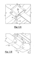
- another air spring seat 86 includes a single stepped shaped member having an air spring seat area 88 and an extended mount area 90.
- a mounting plate 92 engages the extended mount area 90 such that apertures need not be formed therethrough for the U-bolts 94.
- the mounting plate 92 is preferably U-shaped having flanges 96 which contact the beam 72 ( Figure 10B) and provide an engagement surface for fasteners 97 which engage the U-bolts 94.
- a rolled end 91 of the extended mounting area 90 provides mounting location for a shock.
Landscapes
- Engineering & Computer Science (AREA)
- Mechanical Engineering (AREA)
- Vehicle Body Suspensions (AREA)
Applications Claiming Priority (2)
| Application Number | Priority Date | Filing Date | Title |
|---|---|---|---|
| US10/365,000 US6966568B2 (en) | 2003-02-12 | 2003-02-12 | Multi-function bracket for an air suspension |
| US365000 | 2003-02-12 |
Publications (2)
| Publication Number | Publication Date |
|---|---|
| EP1447248A2 true EP1447248A2 (fr) | 2004-08-18 |
| EP1447248A3 EP1447248A3 (fr) | 2004-11-10 |
Family
ID=32681702
Family Applications (1)
| Application Number | Title | Priority Date | Filing Date |
|---|---|---|---|
| EP04250409A Withdrawn EP1447248A3 (fr) | 2003-02-12 | 2004-01-26 | Support pour un ressort à air |
Country Status (3)
| Country | Link |
|---|---|
| US (1) | US6966568B2 (fr) |
| EP (1) | EP1447248A3 (fr) |
| JP (1) | JP2004244012A (fr) |
Families Citing this family (15)
| Publication number | Priority date | Publication date | Assignee | Title |
|---|---|---|---|---|
| US7175190B2 (en) * | 2004-03-30 | 2007-02-13 | Arvinmeritor Technology, Llc | Horizontal mount of suspension element to axle |
| SE529758C2 (sv) * | 2005-07-20 | 2007-11-20 | Volvo Lastvagnar Ab | Individuell hjulupphängning |
| WO2008140805A1 (fr) * | 2007-05-11 | 2008-11-20 | Tlc Suspensions, Llc | Systeme de suspension a combinaison ressort pneumatique/ressort helicoidal reglable |
| US7971890B2 (en) * | 2007-07-16 | 2011-07-05 | Reyco Granning, Llc | Independent suspension assembly |
| KR200458654Y1 (ko) | 2010-08-09 | 2012-03-06 | 주식회사 토신 | 에어 서스펜션 장치의 리프트 백 고정용 리프트 브라켓. |
| DE102011086517A1 (de) * | 2011-11-17 | 2013-05-23 | Zf Friedrichshafen Ag | Starrachse mit Luftfederung |
| GB2514536B (en) * | 2013-03-18 | 2017-05-03 | Alexander Dennis Ltd | Suspension arrangement |
| US9492695B2 (en) | 2014-11-24 | 2016-11-15 | Oshkosh Corporation | Pedestal and torque box assembly for a fire apparatus |
| US9579530B2 (en) | 2014-11-24 | 2017-02-28 | Oshkosh Corporation | Ladder assembly for a fire apparatus |
| US9580962B2 (en) | 2014-11-24 | 2017-02-28 | Oshkosh Corporation | Outrigger assembly for a fire apparatus |
| US9677334B2 (en) | 2014-11-24 | 2017-06-13 | Oshkosh Corporation | Aerial ladder for a fire apparatus |
| US9504863B2 (en) | 2014-11-24 | 2016-11-29 | Oshkosh Corporation | Quint configuration fire apparatus |
| US10286239B2 (en) | 2017-02-08 | 2019-05-14 | Oshkosh Corporation | Fire apparatus piercing tip ranging and alignment system |
| CN113895197A (zh) * | 2021-11-08 | 2022-01-07 | 一汽解放汽车有限公司 | 空气悬架托臂、空气悬架系统及车辆 |
| CN114290888B (zh) * | 2022-01-21 | 2024-02-09 | 安徽永泰汽车零部件有限公司 | 一种汽车发动机悬置托架软垫总成 |
Citations (11)
| Publication number | Priority date | Publication date | Assignee | Title |
|---|---|---|---|---|
| US2874956A (en) * | 1954-12-20 | 1959-02-24 | Gen Motors Corp | Leaf and air spring suspension |
| US3285621A (en) * | 1965-01-12 | 1966-11-15 | Jr Stephen Turner | Wheeled vehicle suspension |
| US3617072A (en) * | 1970-02-17 | 1971-11-02 | Charles E Wern Jr | Drop-axle suspension system |
| US3730549A (en) * | 1970-02-17 | 1973-05-01 | Wern C | Drop-axle suspension system |
| US3730550A (en) * | 1971-06-24 | 1973-05-01 | Ride Rite Corp | Air-spring assembly for vehicles |
| US3877718A (en) * | 1972-09-29 | 1975-04-15 | Twm Mfg Co | High strength auxiliary axle suspension system |
| US4000913A (en) * | 1974-11-08 | 1977-01-04 | Twm Manufacturing Company, Inc. | Lightweight high strength auxiliary lift axle suspension system for high framed vehicles |
| GB2141677A (en) * | 1983-05-20 | 1985-01-03 | Leyland Vehicles | Tapered leaf spring bus suspension |
| US4923210A (en) * | 1989-03-28 | 1990-05-08 | Heider Merle J | Suspension and leveling system for a vehicle |
| US5560641A (en) * | 1994-08-08 | 1996-10-01 | The Boler Company. | Suspension for light duty trucks |
| US20030030236A1 (en) * | 2000-05-04 | 2003-02-13 | Glass Michael Franklin | Vehicle suspension systems |
Family Cites Families (9)
| Publication number | Priority date | Publication date | Assignee | Title |
|---|---|---|---|---|
| US5335932A (en) * | 1992-06-26 | 1994-08-09 | Nai Neway, Inc. | Apparatus for mounting a trailing arm air suspension to a sliding frame |
| US5354091A (en) * | 1992-09-01 | 1994-10-11 | The Binkley Company | Wheeled vehicle suspensions |
| US5470096A (en) * | 1994-03-25 | 1995-11-28 | The Binkley Company | Wheeled vehicle suspension |
| AUPN032694A0 (en) * | 1994-12-23 | 1995-01-27 | Thanksmate Pty Ltd | Improved vehicle |
| US5950971A (en) * | 1996-06-28 | 1999-09-14 | The Boler Company | Assembly for and method of mounting a suspension member to an axle housing |
| US6213507B1 (en) * | 1998-05-20 | 2001-04-10 | The Boler Company | Vehicle trailer frame cross member/suspension assembly mount |
| US6250613B1 (en) * | 1999-03-30 | 2001-06-26 | Bridgestone/Firestone, Inc. | Non-metallic spacer for air spring assembly |
| US6428027B1 (en) * | 2000-05-22 | 2002-08-06 | The Boler Company | Front axle air suspension |
| US6394474B1 (en) * | 2000-07-06 | 2002-05-28 | International Truck Intellectual Property Company, L.L.C. | Front air spring suspension with anti-dive and anti-roll properties |
-
2003
- 2003-02-12 US US10/365,000 patent/US6966568B2/en not_active Expired - Lifetime
-
2004
- 2004-01-26 EP EP04250409A patent/EP1447248A3/fr not_active Withdrawn
- 2004-02-10 JP JP2004033328A patent/JP2004244012A/ja active Pending
Patent Citations (11)
| Publication number | Priority date | Publication date | Assignee | Title |
|---|---|---|---|---|
| US2874956A (en) * | 1954-12-20 | 1959-02-24 | Gen Motors Corp | Leaf and air spring suspension |
| US3285621A (en) * | 1965-01-12 | 1966-11-15 | Jr Stephen Turner | Wheeled vehicle suspension |
| US3617072A (en) * | 1970-02-17 | 1971-11-02 | Charles E Wern Jr | Drop-axle suspension system |
| US3730549A (en) * | 1970-02-17 | 1973-05-01 | Wern C | Drop-axle suspension system |
| US3730550A (en) * | 1971-06-24 | 1973-05-01 | Ride Rite Corp | Air-spring assembly for vehicles |
| US3877718A (en) * | 1972-09-29 | 1975-04-15 | Twm Mfg Co | High strength auxiliary axle suspension system |
| US4000913A (en) * | 1974-11-08 | 1977-01-04 | Twm Manufacturing Company, Inc. | Lightweight high strength auxiliary lift axle suspension system for high framed vehicles |
| GB2141677A (en) * | 1983-05-20 | 1985-01-03 | Leyland Vehicles | Tapered leaf spring bus suspension |
| US4923210A (en) * | 1989-03-28 | 1990-05-08 | Heider Merle J | Suspension and leveling system for a vehicle |
| US5560641A (en) * | 1994-08-08 | 1996-10-01 | The Boler Company. | Suspension for light duty trucks |
| US20030030236A1 (en) * | 2000-05-04 | 2003-02-13 | Glass Michael Franklin | Vehicle suspension systems |
Also Published As
| Publication number | Publication date |
|---|---|
| JP2004244012A (ja) | 2004-09-02 |
| US20040155426A1 (en) | 2004-08-12 |
| US6966568B2 (en) | 2005-11-22 |
| EP1447248A3 (fr) | 2004-11-10 |
Similar Documents
| Publication | Publication Date | Title |
|---|---|---|
| EP1874568B1 (fr) | Suspensions de vehicule comprenant des ressorts a lames et des groupes de pinces alternatives | |
| US6966568B2 (en) | Multi-function bracket for an air suspension | |
| EP1089889B1 (fr) | Systeme d'essieu/suspension a leviers longitudinaux et barres de torsion | |
| CA2880533C (fr) | Suspension d'essieu de vehicule automobile a ressort a lames longitudinal | |
| EP1663677B1 (fr) | Essieu rigide destine a un vehicule et comprenant des bras longitudinaux monoblocs | |
| US9193236B2 (en) | Heavy-duty vehicle axle-to-beam or crossbrace-to-beam connection | |
| US9114685B2 (en) | Reduced weight axle coupling assembly for vehicle suspension systems | |
| US20070187919A1 (en) | Height adjustment blocks for leaf spring suspension | |
| EP1289783B1 (fr) | Suspension pneumatique d'essieu avant | |
| US7618049B2 (en) | Trailing arm suspension | |
| CA2537756C (fr) | Systeme essieu/suspension a bras monobloc | |
| US20070267790A1 (en) | Golf car sliding rear leaf spring | |
| US4533157A (en) | Rear offset axle suspension system for vehicle | |
| US5979920A (en) | Jounce stop apparatus for use in a vehicle suspension | |
| US7188850B2 (en) | Beam axle suspension with diagonal link | |
| EP0752933B1 (fr) | Suspension a bras longitudinal | |
| US7229098B2 (en) | Frame rail torsion attenuator | |
| JP3487213B2 (ja) | 車両のサブフレーム構造 | |
| US6820884B2 (en) | Integrated axle adaptor and spring seat for a vehicle suspension system | |
| JP3704998B2 (ja) | エアスプリング取付構造 | |
| US20070241527A1 (en) | Vehicle suspension with resilient rod linkage |
Legal Events
| Date | Code | Title | Description |
|---|---|---|---|
| PUAI | Public reference made under article 153(3) epc to a published international application that has entered the european phase |
Free format text: ORIGINAL CODE: 0009012 |
|
| AK | Designated contracting states |
Kind code of ref document: A2 Designated state(s): AT BE BG CH CY CZ DE DK EE ES FI FR GB GR HU IE IT LI LU MC NL PT RO SE SI SK TR |
|
| AX | Request for extension of the european patent |
Extension state: AL LT LV MK |
|
| PUAL | Search report despatched |
Free format text: ORIGINAL CODE: 0009013 |
|
| AK | Designated contracting states |
Kind code of ref document: A3 Designated state(s): AT BE BG CH CY CZ DE DK EE ES FI FR GB GR HU IE IT LI LU MC NL PT RO SE SI SK TR |
|
| AX | Request for extension of the european patent |
Extension state: AL LT LV MK |
|
| 17P | Request for examination filed |
Effective date: 20041220 |
|
| 17Q | First examination report despatched |
Effective date: 20050504 |
|
| AKX | Designation fees paid |
Designated state(s): DE FR GB IT |
|
| 17Q | First examination report despatched |
Effective date: 20050504 |
|
| GRAP | Despatch of communication of intention to grant a patent |
Free format text: ORIGINAL CODE: EPIDOSNIGR1 |
|
| STAA | Information on the status of an ep patent application or granted ep patent |
Free format text: STATUS: THE APPLICATION IS DEEMED TO BE WITHDRAWN |
|
| 18D | Application deemed to be withdrawn |
Effective date: 20080408 |