EP1446197B1 - Filtering face mask that uses an exhalation valve that has a multilayered flexible flap - Google Patents
Filtering face mask that uses an exhalation valve that has a multilayered flexible flap Download PDFInfo
- Publication number
- EP1446197B1 EP1446197B1 EP02778420A EP02778420A EP1446197B1 EP 1446197 B1 EP1446197 B1 EP 1446197B1 EP 02778420 A EP02778420 A EP 02778420A EP 02778420 A EP02778420 A EP 02778420A EP 1446197 B1 EP1446197 B1 EP 1446197B1
- Authority
- EP
- European Patent Office
- Prior art keywords
- layer
- valve
- flap
- seal surface
- face mask
- Prior art date
- Legal status (The legal status is an assumption and is not a legal conclusion. Google has not performed a legal analysis and makes no representation as to the accuracy of the status listed.)
- Expired - Lifetime
Links
- 238000001914 filtration Methods 0.000 title claims abstract description 73
- 239000012530 fluid Substances 0.000 claims abstract description 28
- 238000004891 communication Methods 0.000 claims abstract description 4
- 239000000463 material Substances 0.000 claims description 59
- 230000007935 neutral effect Effects 0.000 claims description 8
- 239000002861 polymer material Substances 0.000 claims description 2
- 239000010410 layer Substances 0.000 description 227
- 239000003570 air Substances 0.000 description 65
- 238000012360 testing method Methods 0.000 description 40
- 238000010276 construction Methods 0.000 description 26
- 229920001971 elastomer Polymers 0.000 description 26
- 239000007789 gas Substances 0.000 description 26
- 239000000806 elastomer Substances 0.000 description 16
- -1 polyethylene terephthalate Polymers 0.000 description 13
- YXFVVABEGXRONW-UHFFFAOYSA-N Toluene Chemical compound CC1=CC=CC=C1 YXFVVABEGXRONW-UHFFFAOYSA-N 0.000 description 12
- 238000000034 method Methods 0.000 description 11
- 229920000642 polymer Polymers 0.000 description 11
- 239000000835 fiber Substances 0.000 description 10
- 239000005060 rubber Substances 0.000 description 10
- 239000000203 mixture Substances 0.000 description 9
- 238000007493 shaping process Methods 0.000 description 9
- 239000000243 solution Substances 0.000 description 9
- 238000010998 test method Methods 0.000 description 8
- 239000002245 particle Substances 0.000 description 7
- 230000029058 respiratory gaseous exchange Effects 0.000 description 6
- 239000000356 contaminant Substances 0.000 description 5
- 229920003023 plastic Polymers 0.000 description 5
- 239000004033 plastic Substances 0.000 description 5
- 229920000728 polyester Polymers 0.000 description 5
- 229920002725 thermoplastic elastomer Polymers 0.000 description 5
- RTZKZFJDLAIYFH-UHFFFAOYSA-N Diethyl ether Chemical compound CCOCC RTZKZFJDLAIYFH-UHFFFAOYSA-N 0.000 description 4
- 239000004698 Polyethylene Substances 0.000 description 4
- 239000004743 Polypropylene Substances 0.000 description 4
- 229910052782 aluminium Inorganic materials 0.000 description 4
- XAGFODPZIPBFFR-UHFFFAOYSA-N aluminium Chemical compound [Al] XAGFODPZIPBFFR-UHFFFAOYSA-N 0.000 description 4
- 238000005452 bending Methods 0.000 description 4
- 238000000576 coating method Methods 0.000 description 4
- 230000000052 comparative effect Effects 0.000 description 4
- 229920006225 ethylene-methyl acrylate Polymers 0.000 description 4
- 239000005043 ethylene-methyl acrylate Substances 0.000 description 4
- 238000004519 manufacturing process Methods 0.000 description 4
- 229920000515 polycarbonate Polymers 0.000 description 4
- 239000004417 polycarbonate Substances 0.000 description 4
- 229920000573 polyethylene Polymers 0.000 description 4
- 229920001155 polypropylene Polymers 0.000 description 4
- 230000000241 respiratory effect Effects 0.000 description 4
- 230000004044 response Effects 0.000 description 4
- 229920000468 styrene butadiene styrene block copolymer Polymers 0.000 description 4
- 229920002799 BoPET Polymers 0.000 description 3
- 229920001634 Copolyester Polymers 0.000 description 3
- 229920001410 Microfiber Polymers 0.000 description 3
- 239000004677 Nylon Substances 0.000 description 3
- 239000011248 coating agent Substances 0.000 description 3
- 238000005520 cutting process Methods 0.000 description 3
- 230000006872 improvement Effects 0.000 description 3
- 239000003658 microfiber Substances 0.000 description 3
- 229920001778 nylon Polymers 0.000 description 3
- 230000036961 partial effect Effects 0.000 description 3
- 229920000139 polyethylene terephthalate Polymers 0.000 description 3
- 239000005020 polyethylene terephthalate Substances 0.000 description 3
- 229920001195 polyisoprene Polymers 0.000 description 3
- 230000008569 process Effects 0.000 description 3
- 238000010926 purge Methods 0.000 description 3
- 239000002356 single layer Substances 0.000 description 3
- 238000007655 standard test method Methods 0.000 description 3
- 238000003756 stirring Methods 0.000 description 3
- 239000000758 substrate Substances 0.000 description 3
- 229920001169 thermoplastic Polymers 0.000 description 3
- 239000004416 thermosoftening plastic Substances 0.000 description 3
- OQEBBZSWEGYTPG-UHFFFAOYSA-N 3-aminobutanoic acid Chemical compound CC(N)CC(O)=O OQEBBZSWEGYTPG-UHFFFAOYSA-N 0.000 description 2
- CURLTUGMZLYLDI-UHFFFAOYSA-N Carbon dioxide Chemical compound O=C=O CURLTUGMZLYLDI-UHFFFAOYSA-N 0.000 description 2
- 229920002633 Kraton (polymer) Polymers 0.000 description 2
- 229920000459 Nitrile rubber Polymers 0.000 description 2
- MCMNRKCIXSYSNV-UHFFFAOYSA-N Zirconium dioxide Chemical compound O=[Zr]=O MCMNRKCIXSYSNV-UHFFFAOYSA-N 0.000 description 2
- 230000004913 activation Effects 0.000 description 2
- 239000000853 adhesive Substances 0.000 description 2
- 230000001070 adhesive effect Effects 0.000 description 2
- QVGXLLKOCUKJST-UHFFFAOYSA-N atomic oxygen Chemical compound [O] QVGXLLKOCUKJST-UHFFFAOYSA-N 0.000 description 2
- 229920001400 block copolymer Polymers 0.000 description 2
- 229920005549 butyl rubber Polymers 0.000 description 2
- 239000000919 ceramic Substances 0.000 description 2
- HGVPOWOAHALJHA-UHFFFAOYSA-N ethene;methyl prop-2-enoate Chemical compound C=C.COC(=O)C=C HGVPOWOAHALJHA-UHFFFAOYSA-N 0.000 description 2
- 238000011156 evaluation Methods 0.000 description 2
- 238000001125 extrusion Methods 0.000 description 2
- 239000002657 fibrous material Substances 0.000 description 2
- 239000011521 glass Substances 0.000 description 2
- 230000005484 gravity Effects 0.000 description 2
- 239000004615 ingredient Substances 0.000 description 2
- 238000001746 injection moulding Methods 0.000 description 2
- 229910052751 metal Inorganic materials 0.000 description 2
- 239000002184 metal Substances 0.000 description 2
- 239000001301 oxygen Substances 0.000 description 2
- 229910052760 oxygen Inorganic materials 0.000 description 2
- 229920001084 poly(chloroprene) Polymers 0.000 description 2
- 229920001200 poly(ethylene-vinyl acetate) Polymers 0.000 description 2
- 229920000058 polyacrylate Polymers 0.000 description 2
- 229920005996 polystyrene-poly(ethylene-butylene)-polystyrene Polymers 0.000 description 2
- 229920002635 polyurethane Polymers 0.000 description 2
- 239000004814 polyurethane Substances 0.000 description 2
- 229920005989 resin Polymers 0.000 description 2
- 239000011347 resin Substances 0.000 description 2
- 230000000284 resting effect Effects 0.000 description 2
- 229920002379 silicone rubber Polymers 0.000 description 2
- 239000004945 silicone rubber Substances 0.000 description 2
- 239000002904 solvent Substances 0.000 description 2
- 230000003068 static effect Effects 0.000 description 2
- 239000000126 substance Substances 0.000 description 2
- 229920001187 thermosetting polymer Polymers 0.000 description 2
- WSSSPWUEQFSQQG-UHFFFAOYSA-N 4-methyl-1-pentene Chemical compound CC(C)CC=C WSSSPWUEQFSQQG-UHFFFAOYSA-N 0.000 description 1
- 241000208140 Acer Species 0.000 description 1
- 241000894006 Bacteria Species 0.000 description 1
- ZOXJGFHDIHLPTG-UHFFFAOYSA-N Boron Chemical compound [B] ZOXJGFHDIHLPTG-UHFFFAOYSA-N 0.000 description 1
- 229910001369 Brass Inorganic materials 0.000 description 1
- 229920003313 Bynel® Polymers 0.000 description 1
- 241000218645 Cedrus Species 0.000 description 1
- 229920003939 DuPont™ Surlyn® 1650 Polymers 0.000 description 1
- 229920002943 EPDM rubber Polymers 0.000 description 1
- 229920003345 Elvax® Polymers 0.000 description 1
- 229920000181 Ethylene propylene rubber Polymers 0.000 description 1
- 240000000731 Fagus sylvatica Species 0.000 description 1
- 235000010099 Fagus sylvatica Nutrition 0.000 description 1
- YCKRFDGAMUMZLT-UHFFFAOYSA-N Fluorine atom Chemical compound [F] YCKRFDGAMUMZLT-UHFFFAOYSA-N 0.000 description 1
- 244000043261 Hevea brasiliensis Species 0.000 description 1
- OWYWGLHRNBIFJP-UHFFFAOYSA-N Ipazine Chemical compound CCN(CC)C1=NC(Cl)=NC(NC(C)C)=N1 OWYWGLHRNBIFJP-UHFFFAOYSA-N 0.000 description 1
- 229920000106 Liquid crystal polymer Polymers 0.000 description 1
- 239000004977 Liquid-crystal polymers (LCPs) Substances 0.000 description 1
- 229920004061 Makrolon® 3108 Polymers 0.000 description 1
- 229920000877 Melamine resin Polymers 0.000 description 1
- 229910000861 Mg alloy Inorganic materials 0.000 description 1
- 239000005041 Mylar™ Substances 0.000 description 1
- UFWIBTONFRDIAS-UHFFFAOYSA-N Naphthalene Chemical compound C1=CC=CC2=CC=CC=C21 UFWIBTONFRDIAS-UHFFFAOYSA-N 0.000 description 1
- 229910000990 Ni alloy Inorganic materials 0.000 description 1
- 239000002033 PVDF binder Substances 0.000 description 1
- 229930040373 Paraformaldehyde Natural products 0.000 description 1
- 235000014676 Phragmites communis Nutrition 0.000 description 1
- 241000218657 Picea Species 0.000 description 1
- 229920000034 Plastomer Polymers 0.000 description 1
- 239000004696 Poly ether ether ketone Substances 0.000 description 1
- 239000004962 Polyamide-imide Substances 0.000 description 1
- 239000005062 Polybutadiene Substances 0.000 description 1
- 239000004697 Polyetherimide Substances 0.000 description 1
- 239000004642 Polyimide Substances 0.000 description 1
- 239000004793 Polystyrene Substances 0.000 description 1
- 229920001328 Polyvinylidene chloride Polymers 0.000 description 1
- GOOHAUXETOMSMM-UHFFFAOYSA-N Propylene oxide Chemical compound CC1CO1 GOOHAUXETOMSMM-UHFFFAOYSA-N 0.000 description 1
- 229910000831 Steel Inorganic materials 0.000 description 1
- RTAQQCXQSZGOHL-UHFFFAOYSA-N Titanium Chemical compound [Ti] RTAQQCXQSZGOHL-UHFFFAOYSA-N 0.000 description 1
- 241000700605 Viruses Species 0.000 description 1
- XECAHXYUAAWDEL-UHFFFAOYSA-N acrylonitrile butadiene styrene Chemical compound C=CC=C.C=CC#N.C=CC1=CC=CC=C1 XECAHXYUAAWDEL-UHFFFAOYSA-N 0.000 description 1
- 239000004676 acrylonitrile butadiene styrene Substances 0.000 description 1
- 229920000122 acrylonitrile butadiene styrene Polymers 0.000 description 1
- 239000000654 additive Substances 0.000 description 1
- 239000012080 ambient air Substances 0.000 description 1
- 230000009286 beneficial effect Effects 0.000 description 1
- 239000008280 blood Substances 0.000 description 1
- 210000004369 blood Anatomy 0.000 description 1
- 229910052796 boron Inorganic materials 0.000 description 1
- 239000010951 brass Substances 0.000 description 1
- FACXGONDLDSNOE-UHFFFAOYSA-N buta-1,3-diene;styrene Chemical compound C=CC=C.C=CC1=CC=CC=C1.C=CC1=CC=CC=C1 FACXGONDLDSNOE-UHFFFAOYSA-N 0.000 description 1
- 229910002092 carbon dioxide Inorganic materials 0.000 description 1
- 239000001569 carbon dioxide Substances 0.000 description 1
- 239000003795 chemical substances by application Substances 0.000 description 1
- 229920006235 chlorinated polyethylene elastomer Polymers 0.000 description 1
- 238000013329 compounding Methods 0.000 description 1
- 238000004132 cross linking Methods 0.000 description 1
- 239000002178 crystalline material Substances 0.000 description 1
- 238000007872 degassing Methods 0.000 description 1
- 238000013461 design Methods 0.000 description 1
- 238000011161 development Methods 0.000 description 1
- 239000010432 diamond Substances 0.000 description 1
- 229910003460 diamond Inorganic materials 0.000 description 1
- 239000000428 dust Substances 0.000 description 1
- 230000000694 effects Effects 0.000 description 1
- 239000013536 elastomeric material Substances 0.000 description 1
- 238000009713 electroplating Methods 0.000 description 1
- 238000005516 engineering process Methods 0.000 description 1
- 229920005558 epichlorohydrin rubber Polymers 0.000 description 1
- 229920006228 ethylene acrylate copolymer Polymers 0.000 description 1
- 229920006229 ethylene acrylic elastomer Polymers 0.000 description 1
- 239000005038 ethylene vinyl acetate Substances 0.000 description 1
- 238000007765 extrusion coating Methods 0.000 description 1
- 230000001815 facial effect Effects 0.000 description 1
- 229920002457 flexible plastic Polymers 0.000 description 1
- 239000011737 fluorine Substances 0.000 description 1
- 229910052731 fluorine Inorganic materials 0.000 description 1
- 125000001153 fluoro group Chemical group F* 0.000 description 1
- 239000006261 foam material Substances 0.000 description 1
- 239000011888 foil Substances 0.000 description 1
- 238000012812 general test Methods 0.000 description 1
- 239000006112 glass ceramic composition Substances 0.000 description 1
- 230000036541 health Effects 0.000 description 1
- 229920001903 high density polyethylene Polymers 0.000 description 1
- 229920005669 high impact polystyrene Polymers 0.000 description 1
- 239000004700 high-density polyethylene Substances 0.000 description 1
- 239000004797 high-impact polystyrene Substances 0.000 description 1
- 239000012456 homogeneous solution Substances 0.000 description 1
- 229930195733 hydrocarbon Natural products 0.000 description 1
- 150000002430 hydrocarbons Chemical class 0.000 description 1
- 230000010354 integration Effects 0.000 description 1
- 229920000554 ionomer Polymers 0.000 description 1
- 238000003475 lamination Methods 0.000 description 1
- 229920000126 latex Polymers 0.000 description 1
- 229920000092 linear low density polyethylene Polymers 0.000 description 1
- 239000004707 linear low-density polyethylene Substances 0.000 description 1
- 239000007788 liquid Substances 0.000 description 1
- 238000011068 loading method Methods 0.000 description 1
- 230000008376 long-term health Effects 0.000 description 1
- 229920001684 low density polyethylene Polymers 0.000 description 1
- 239000004702 low-density polyethylene Substances 0.000 description 1
- 238000005259 measurement Methods 0.000 description 1
- 150000007974 melamines Chemical class 0.000 description 1
- 150000002739 metals Chemical class 0.000 description 1
- 230000003278 mimic effect Effects 0.000 description 1
- 239000003595 mist Substances 0.000 description 1
- 229920003052 natural elastomer Polymers 0.000 description 1
- 229920001194 natural rubber Polymers 0.000 description 1
- 238000004806 packaging method and process Methods 0.000 description 1
- 244000052769 pathogen Species 0.000 description 1
- 230000002093 peripheral effect Effects 0.000 description 1
- 229920003221 poly(phosphazene) elastomer Polymers 0.000 description 1
- 229920013639 polyalphaolefin Polymers 0.000 description 1
- 229920002312 polyamide-imide Polymers 0.000 description 1
- 229920002857 polybutadiene Polymers 0.000 description 1
- 229920001707 polybutylene terephthalate Polymers 0.000 description 1
- 229920002530 polyetherether ketone Polymers 0.000 description 1
- 229920001601 polyetherimide Polymers 0.000 description 1
- 229920001721 polyimide Polymers 0.000 description 1
- 229920000098 polyolefin Polymers 0.000 description 1
- 229920006324 polyoxymethylene Polymers 0.000 description 1
- 229920001296 polysiloxane Polymers 0.000 description 1
- 229920002223 polystyrene Polymers 0.000 description 1
- 229920000346 polystyrene-polyisoprene block-polystyrene Polymers 0.000 description 1
- 229920001021 polysulfide Polymers 0.000 description 1
- 239000005033 polyvinylidene chloride Substances 0.000 description 1
- 229920002981 polyvinylidene fluoride Polymers 0.000 description 1
- 239000000843 powder Substances 0.000 description 1
- 239000011253 protective coating Substances 0.000 description 1
- 230000001681 protective effect Effects 0.000 description 1
- 230000009467 reduction Effects 0.000 description 1
- 230000002829 reductive effect Effects 0.000 description 1
- 230000001105 regulatory effect Effects 0.000 description 1
- 239000002990 reinforced plastic Substances 0.000 description 1
- 238000011160 research Methods 0.000 description 1
- 210000002345 respiratory system Anatomy 0.000 description 1
- 230000024042 response to gravity Effects 0.000 description 1
- 210000003296 saliva Anatomy 0.000 description 1
- 229920003031 santoprene Polymers 0.000 description 1
- 238000007789 sealing Methods 0.000 description 1
- 238000000926 separation method Methods 0.000 description 1
- 238000010008 shearing Methods 0.000 description 1
- 239000007787 solid Substances 0.000 description 1
- 239000002594 sorbent Substances 0.000 description 1
- 239000010935 stainless steel Substances 0.000 description 1
- 229910001220 stainless steel Inorganic materials 0.000 description 1
- 239000010959 steel Substances 0.000 description 1
- 229920003048 styrene butadiene rubber Polymers 0.000 description 1
- 239000002344 surface layer Substances 0.000 description 1
- 229920003051 synthetic elastomer Polymers 0.000 description 1
- 238000009864 tensile test Methods 0.000 description 1
- 239000010936 titanium Substances 0.000 description 1
- 229910052719 titanium Inorganic materials 0.000 description 1
- 231100000331 toxic Toxicity 0.000 description 1
- 230000002588 toxic effect Effects 0.000 description 1
- 238000012546 transfer Methods 0.000 description 1
- WFKWXMTUELFFGS-UHFFFAOYSA-N tungsten Chemical compound [W] WFKWXMTUELFFGS-UHFFFAOYSA-N 0.000 description 1
- 239000010937 tungsten Substances 0.000 description 1
- 229910052721 tungsten Inorganic materials 0.000 description 1
- 229920001862 ultra low molecular weight polyethylene Polymers 0.000 description 1
- 238000007740 vapor deposition Methods 0.000 description 1
- 239000011800 void material Substances 0.000 description 1
- XLYOFNOQVPJJNP-UHFFFAOYSA-N water Substances O XLYOFNOQVPJJNP-UHFFFAOYSA-N 0.000 description 1
- 238000003466 welding Methods 0.000 description 1
Images


Classifications
-
- A—HUMAN NECESSITIES
- A62—LIFE-SAVING; FIRE-FIGHTING
- A62B—DEVICES, APPARATUS OR METHODS FOR LIFE-SAVING
- A62B18/00—Breathing masks or helmets, e.g. affording protection against chemical agents or for use at high altitudes or incorporating a pump or compressor for reducing the inhalation effort
- A62B18/08—Component parts for gas-masks or gas-helmets, e.g. windows, straps, speech transmitters, signal-devices
- A62B18/10—Valves
Definitions
- the present invention pertains to a filtering face mask that uses a multi-layered flexible flap as the dynamic mechanical element in its exhalation valve or in its inhalation valve.
- Filtering face masks typically have a fibrous or sorbent filter that is capable of removing particulate and/or gaseous contaminants from the air.
- wearers When wearing a face mask in a contaminated environment, wearers are comforted with the knowledge that their health is being protected, but they are, however, contemporaneously discomforted by the warm, moist, exhaled air that accumulates around their face. The greater this facial discomfort is, the greater the chances are that wearers will remove the mask from their face to alleviate the unpleasant condition.
- buttons-style exhalation valves on the masks to purge the exhaled air from the mask interiors.
- the button-style valves typically have employed a thin circular flexible flap as the dynamic mechanical element that lets exhaled air escape from the mask interior.
- the flap is centrally mounted to a valve seat through a central post. Examples of button-style valves are shown in U.S. Patents 2,072,516, 2,230,770, 2,895,472, and 4,630,604. When a person exhales, a circumferential portion of the flap is lifted from the valve seat to allow air to escape from the mask interior.
- Button-style valves have represented an advance in the attempt to improve wearer comfort, but investigators have made other improvements, an example of which is shown in U.S. Patent 4,934,362 to Braun.
- the valve described in this patent uses a parabolic valve seat and an elongated flexible flap.
- the Braun valve also has a centrally-mounted flap and has a flap edge portion that lifts from a seal surface during an exhalation to allow the exhaled air to escape from the mask interior.
- the flexible flap has had a monolithic construction.
- the flexible flap that is described in the '362 patent to Braun is made of pure gum rubber, and the flap that is described in the Japuntich et al. patents is made solely from an elastomeric material such as a crosslinked natural rubber (for example, crosslinked polyisoprene) or a synthetic elastomer such as neoprene, butyl rubber, nitrile rubber, or silicone rubber.
- a crosslinked natural rubber for example, crosslinked polyisoprene
- a synthetic elastomer such as neoprene, butyl rubber, nitrile rubber, or silicone rubber.
- the present invention provides a new filtering face mask, which in brief summary, comprises: (a) a mask body that is adapted to fit at least over the nose and mouth of a wearer to create an interior gas space when worn; and (b) an exhalation valve that is in fluid communication with the interior gas space.
- the exhalation valve comprises: (i) a valve seat that includes a seal surface and an orifice through which exhaled air may pass to leave the interior gas space; and (ii) a flexible flap that is mounted to the valve seat such that the flap makes contact with the seal surface when the valve is in its closed position and such that the flap can flex away from the seal surface during an exhalation to allow exhaled air to pass through the orifice.
- the flexible flap includes first and second juxtaposed layers where at least one of the layers is stiffer or has a greater modulus of elasticity than the other layer.
- the inventors discovered that the use of a multi-layered flexible flap in a unidirectional fluid valve can provide performance benefits to an exhalation valve for a filtering face mask.
- a thinner and more dynamic flexible flap may be used in some instances, which can allow the valve to open easier under less pressure drop to enable warm, moist, exhaled air to escape from the mask interior under less exhalation pressure. Wearers therefore may be able to purge larger amounts of exhaled air from the interior gas space more rapidly without expending as much power, resulting in improved comfort to the mask wearer.
- flap-to-flap variability may not need to be so tightly controlled during the manufacturing process because one layer in the flap can be easily fashioned to provide the flap with its desired beam stiffness. Overall flap thickness tolerances then do not need to be so tightly controlled during manufacture.
- the structure and benefits of the new exhalation valve may also be applied to an inhalation valve, where the flow through the valve is likewise unidirectional and where improvements in pressure drop across the valve are similarly beneficial to wearer comfort.
- a new filtering face mask may improve wearer comfort and concomitantly make it more likely that users will continuously wear their masks in contaminated environments.
- the present invention thus may improve worker safety and provide long term health benefits to workers and others who wear personal respiratory protection devices.
- FIG. 1 illustrates an example of a filtering face mask 10 that may be used in conjunction with the present invention.
- Filtering face mask 10 has a cup-shaped mask body 12 onto which an exhalation valve 14 is attached.
- the valve may be attached to the mask body using any suitable technique, including, for example, the technique described in U.S. Patent 6,125,849 to Williams et al. or in WO 01/28634 to Curran et al.
- the exhalation valve 14 opens in response to increased pressure inside the mask 10, which increased pressure occurs when a wearer exhales.
- the exhalation valve 14 preferably remains closed between breaths and during an inhalation.
- Mask body 12 is adapted to fit over the nose and mouth of a person in spaced relation to the wearer's face to create an interior gas space or void between the wearer's face and the interior surface of the mask body.
- the mask body 12 is fluid permeable and typically is provided with an opening (not shown) that is located where the exhalation valve 14 is attached to the mask body 12 so that exhaled air can exit the interior gas space through the valve 14 without having to pass through the mask body 12 .
- the preferred location of the opening on the mask body 12 is directly in front of where the wearer's mouth would be when the mask is being worn. The placement of the opening, and hence the exhalation valve 14, at this location allows the valve to open more easily in response to the exhalation pressure generated by a wearer of the mask 10.
- essentially the entire exposed surface of mask body 12 is fluid permeable to inhaled air.
- a nose clip 16 that comprises a pliable dead soft band of metal such as aluminum can be provided on mask body 12 to allow it to be shaped to hold the face mask in a desired fitting relationship over the nose of the wearer.
- An example of a suitable nose clip is shown in U.S. Patents 5,558,089 and Des. 412,573 to Castiglione.
- Mask body 12 can have a curved, hemispherical shape as shown in FIG. 1 (see also U.S. Patent 4,807,619 to Dyrud et al.) or it may take on other shapes as so desired.
- the mask body can be a cup-shaped mask having a construction like the face mask disclosed in U.S. Patent 4,827,924 to Japuntich.
- the mask also could have the three-fold configuration that can fold flat when not in use but can open into a cup-shaped configuration when worn ⁇ see U.S. Patent 6,123,077 to Bostock et al., and U.S. Patents Des. 431,647 to Henderson et al., Des. 424,688 to Bryant et al.
- Face masks of the invention also may take on many other configurations, such as flat bifold masks disclosed in U.S. Patent Des. 443,927 to Chen.
- the mask body also could be fluid impermeable and have filter cartridges attached to it like the mask shown in U.S. Patent 5,062,421 to Bums and Reischel.
- the mask body also could be adapted for use with a positive pressure air intake as opposed to the negative pressure masks just described. Examples of positive pressure masks are shown in U.S. Patent 5,924,420 to Grannis et al. and 4,790,306 to Braun et al.
- the mask body of the filtering face mask also could be connected to a self-contained breathing apparatus, which supplies clean air to the wearer as disclosed, for example, in U.S. Patents 5,035,239 and 4,971,052.
- the mask body may be configured to cover not only the nose and mouth of the wearer (referred to as a "half mask") but may also cover the eyes (referred to as a "full face mask”) to provide protection to a wearer's vision as well as to the wearer's respiratory system ⁇ see, for example, U.S. Patent 5,924,420 to Reischel et al.
- the mask body may be spaced from the wearer's face, or it may reside flush or in close proximity to it.
- the mask helps define an interior gas space into which exhaled air passes before leaving the mask interior through the exhalation valve.
- the mask body also could have a thermochromic fit-indicating seal at its periphery to allow the wearer to easily ascertain if a proper fit has been established ⁇ see U.S. Patent 5,617,849 to Springett et al.
- mask body can have a harness such as straps 15 , tie strings, or any other suitable means attached to it for supporting the mask on the wearer's face.
- harnesses that may be suitable are shown in U.S. Patents 5,394,568, and 6,062,221 to Brostrom et al., and U.S. Patent 5,464,010 to Byram.
- FIG. 2 shows that the mask body 12 may comprise multiple layers such as an inner shaping layer 17 and an outer filtration layer 18.
- Shaping layer 17 provides structure to the mask body 12 and support for filtration layer 18.
- Shaping layer 17 may be located on the inside and/or outside of filtration layer 18 (or on both sides) and can be made, for example, from a nonwoven web of thermally-bondable fibers molded into a cup-shaped configuration ⁇ see 4,807,619 to Dyrud et al. and U.S. Patent 4,536,440 to Berg. It can also be made from a porous layer or an open work "fishnet" type network of flexible plastic like the shaping layer disclosed in U.S. Patent 4,850,347 to Skov.
- the shaping layer can be molded in accordance with known procedures such as those described in Skov or in U.S. Patent 5,307,796 to Kronzer et al.
- a shaping layer 17 is designed with the primary purpose of providing structure to the mask and providing support for a filtration layer, shaping layer 17 also may act as a filter typically for capturing larger particles. Together layers 17 and 18 operate as an inhale filter element.
- the filter layer 18 is integral with the mask body 12 ⁇ that is, it forms part of the mask body and is not an item that subsequently becomes attached to (or removed from) the mask body like a filter cartridge.
- Microfibers typically have an average effective fiber diameter of about 20 micrometers ( ⁇ m) or less, but commonly are about I to about 15 ⁇ m, and still more commonly be about 3 to 10 ⁇ m in diameter. Effective fiber diameter may be calculated as described in Davies, C.N., The Separation of Airborne Dust and Particles, Institution of Mechanical Engineers, London, Proceedings 1B. 1952.
- BMF webs can be formed as described in Wente, Van A., Superfine Thermoplastic Fibers in Industrial Engineering Chemistry, vol. 48, pages 1342 et seq.
- BMF webs can have sufficient integrity to be handled as a mat.
- Electric charge can be imparted to fibrous webs using techniques described in, for example, U.S. Patent 5,496,507 to Angadjivand et al., U.S. Patent 4,215,682 to Kubik et al., and U.S. Patent 4,592,815 to Nakao.
- fibrous materials that may be used as filters in a mask body are disclosed in U.S. Patent No. 5,706,804 to Baumann et al., U.S. Patent No. 4,419,993 to Peterson, U.S. Reissue Patent No. Re 28,102 to Mayhew, U.S. Patents 5,472,481 and 5,411,576 to Jones et al., and U.S. Patent 5,908,598 to Rousseau et al.
- the fibers may contain polymers such as polypropylene and/or poly-4-methyl-1-pentene (see U.S. Patents 4,874,399 to Jones et al.
- a mask body 12 may also include inner and/or outer cover webs (not shown) that can protect the filter layer 18 from abrasive forces and that can retain any fibers that may come loose from the filter layer 18 and/or shaping layer 17.
- the cover webs also may have filtering abilities, although typically not nearly as good as the filtering layer 18 and/or may serve to make the mask more comfortable to wear.
- the cover webs may be made from nonwoven fibrous materials such as spun bonded fibers that contain, for example, polyolefins, and polyesters (see, for example, U.S. Patents 6,041,782 to Angadjivand et al.), 4,807,619 to Dyrud et al., and 4,536,440 to Berg.
- FIG. 3 shows that the flexible flap 22 rests on a seal surface 24 when the flap is closed and is also supported in cantilevered fashion to the valve seat 20 at a flap-retaining surface 25.
- the flap 22 lifts from the seal surface 24 at its free end 26 when a significant pressure is reached in the interior gas space during an exhalation.
- the seal surface 24 can be configured to generally curve in the longitudinal dimension in a concave cross-section when viewed from a side elevation and may be non-aligned and relatively positioned with respect to a flap-retaining surface 25 to allow the flap to be biased or pressed towards the seal surface under neutral conditions ⁇ that is, when a wearer is neither inhaling or exhaling.
- the seal surface 24 may reside at the extreme end of a seal ridge 27.
- the flap can also have a transverse curvature imparted to it as described in U.S. Patent 5,687,767, reissued as Re to Bowers.
- the flexible flap 22 is secured at the stationary portion 30 to the valve seat 20 on the flap retaining surface 25, which surface 25 is disposed non-centrally relative to the orifice 28 and can have pins 32 to help mount and position the flap 22 on the valve seat 20.
- Flexible flap 22 can be secured to the surface 25 using sonic welding, an adhesive, mechanical clamping, and the like.
- the valve seat 20 also has a flange 33 that extends laterally from the valve seat 20 at its base to provide a surface that allows the exhalation valve 14 to be secured to the mask body 12 .
- FIG. 3 shows the flexible flap 22 in a closed position resting on seal surface 24 and in an open position by the dotted lines 22a.
- a fluid passes through the valve 14 in the general direction indicated by arrow 34. If valve 14 was used on a filtering face mask to purge exhaled air from the mask interior, fluid flow 34 would represent an exhale flow stream. If valve 14 was used as an inhalation valve, flow stream 34 would represent an inhale flow stream.
- the fluid that passes through orifice 28 exerts a force on the flexible flap 22 , causing the free end 26 of flap 22 to be lifted from seal surface 24 to make the valve 14 open.
- valve 14 When valve 14 is used as an exhalation valve, the valve is preferably oriented on face mask 10 such that the free end 26 of flexible flap 24 is located below the secured end when the mask 10 is positioned upright as shown in FIG. 1. This enables exhaled air to be deflected downwards to prevent moisture from condensing on the wearer's eyewear.
- FIG. 4 shows the valve seat 20 from a front view without a flap being attached to it.
- the valve orifice 28 is disposed radially inward from the seal surface 24 and can have cross members 35 that stabilize the seal surface 24 and ultimately the valve 14 .
- the cross members 35 also can prevent flap 22 (FIG. 3) from inverting into orifice 28 during an inhalation. Moisture build-up on the cross members 35 can hamper the opening of the flap 22 . Therefore, the surfaces of the cross-members 35 that face the flap preferably are slightly recessed beneath the seal surface 24 when viewed from a side elevation to not hamper valve opening.
- the seal surface 24 circumscribes or surrounds the orifice 28 to prevent the undesired passage of contaminates through it.
- Seal surface 24 and the valve orifice 28 can take on essentially any shape when viewed from the front.
- the seal surface 24 and the orifice 28 may be square, rectangular, circular, elliptical, etc.
- the shape of seal surface 24 does not have to correspond to the shape of orifice 28 or vise versa.
- the orifice 28 may be circular and the seal surface 24 may be rectangular.
- the seal surface 24 and orifice 28, however, preferably have a circular cross-section when viewed against the direction of fluid flow.
- Valve seat 20 preferably is made from a relatively lightweight plastic that is molded into an integral one-piece body.
- the valve seat 20 can be made by injection molding techniques.
- the seal surface 24 that makes contact with the flexible flap 22 is preferably fashioned to be substantially uniformly smooth to ensure that a good seal occurs and may reside on the top of a seal ridge.
- the contact surface 24 preferably has a width great enough to form a seal with the flexible flap 22 but is not so wide as to allow adhesive forces caused by condensed moisture to make the flexible flap 22 significantly more difficult to open.
- the width of the seal or contact surface preferably, is at least 0.2 mm, and preferably is about 0.25 mm to 0.5 mm.
- FIG. 5 shows another embodiment of an exhalation valve 14' .
- this exhalation valve has, when viewed from a side elevation, a planar seal surface 24' that is in alignment with the flap-retaining surface 25' .
- the flap shown in FIG. 5 thus is not pressed towards or against the seal surface 24' by virtue of any mechanical force or internal stress that is placed on the flexible flap 22. Because the flap 22 is not biased towards the seal surface 24' under neutral conditions (that is, when no fluid is passing through the valve or the flap is not otherwise subjected to external forces), the flap 22 can open more easily during an exhalation.
- the flap biased or forced into contact with the seal surface 24' ⁇ may not be necessary to have the flap biased or forced into contact with the seal surface 24' ⁇ although such a construction may be desired in some instances.
- the use of a stiffer layer in the flexible flap can stiffen the whole flap so that it does not significantly droop away from the seal surface 24' when a force of gravity is exerted upon the flap.
- the exhalation valve 14' shown in FIG. 5 thus can be fashioned so that the flap 22 makes good contact with the seal surface under any orientation, including when a wearer bends their head downward towards the floor, without having the flap biased (or substantially biased) towards the seal surface.
- a multi-layered flap of the present invention may make hermetic-type contact with the seal surface 24' under any orientation of the valve with very little or no pre-stress or bias towards the valve seat's seal surface.
- the lack of significant predefined stress or force on the flap, to ensure that it is pressed against the seal surface during valve closure under neutral conditions, can enable the flap to open more easily during an exhalation and hence can reduce the power needed to operate the valve while breathing.
- FIG. 6 shows a valve cover 40 that may be suitable for use in connection with the exhalation valves shown in the other figures.
- the valve cover 40 defines an internal chamber into which the flexible flap can move from its closed position to its open position.
- the valve cover 40 can protect the flexible flap from damage and can assist in directing exhaled air downward away from a wearer's eyeglasses.
- the valve cover 40 may possess a plurality of openings 42 to allow exhaled air to escape from the internal chamber defined by the valve cover. Air that exits the internal chamber through the openings 42 enters the exterior gas space, downwardly away from a wearer's eyewear.
- an inhalation valve also is a unidirectional fluid valve that provides for fluid transfer between an exterior gas space and an interior gas space. Unlike an exhalation valve, however, an inhalation valve allows air to enter the interior of a mask body. An inhalation valve thus allows air to move from an exterior gas space to the interior gas space during an inhalation.
- Inhalation valves are commonly used in conjunction with filtering face masks that have filter cartridges attached to them.
- the valve may be second to either the filter cartridge or to the mask body.
- the inhalation valve is preferably disposed in the inhale flow stream downstream to where the air has been filtered or otherwise has been made safe to breathe.
- Examples of commercially available masks that include inhalation valves are the 5000TM and 6000TM Series respirators sold by the 3M Company.
- Patented examples of filtering face masks that use an inhalation valve are disclosed in U.S. Patent 5,062,421 to Bums and Reischel, U.S. Patent 6,216,693 to Rekow et al., and in U.S. Patent 5,924,420 to Reischel et al.
- inhalation valve could take, for example, the form of a button-style valve, alternatively, it could also be a flapper-style valve like the valve shown in FIGs. 1, 3, 4, and 5.
- the valve shown in these figures it merely needs to be mounted to the mask body in an inverted fashion so that the flexible flap 22 lifts from the seal surface 24 or 24' during an inhalation rather than during an exhalation. The flap 22 thus, would be pressed against the seal surface 24, 24' during an exhalation rather than an inhalation.
- An inhalation valve of the present invention could similarly improve wearer comfort by reducing the power needed to operate the inhalation valve while breathing.
- a flexible flap that is constructed for use in a fluid valve of the invention comprises a sheet that is shaped and adapted for attachment to a valve seat of a fluid valve.
- the flexible flap can bend dynamically in response to a force from a moving gaseous flowstream and can readily return to its original position when the force is removed.
- the sheet comprises first and second juxtaposed layers where at least one of the layers is stiffer than the other or has an elastic modulus than the other.
- FIG. 7 shows a flexible flap 22 ⁇ which may be used with valves and face masks in accordance with the present invention ⁇ in an enlarged cross-section so that the multi-layered flap construction can be seen.
- the flap 22 has first and second juxtaposed layers 44 and 46, respectively.
- the layers 44 and 46 are preferably securely bonded together to provide resistance to shearing between layers, but the individual layers do not need to be bonded together at their interface, i.e., the layers may float relative to each other as, for example, in a leaf spring.
- the layers 44 and 46 may be formed of materials that deform elastically over the actuation range of the flexible flap.
- the first layer 44 When secured to the valve, the first layer 44 preferably is disposed on the side of the flap 22 that faces the valve seat's seal surface ( 24, 24' FIGs. 1,3, 4, and 5) when the valve is in its closed position.
- the flap's second layer 46 preferably is disposed away from the seal surface (relative to the first layer) towards the inside surface of the top of the valve cover (FIG. 6).
- the first and second layers 44, 46 are preferably constructed from materials that exhibit different moduli of elasticity.
- FIG. 8 shows another embodiment of a flexible flap 22' that has a multi-layered construction in accordance with the present invention.
- the flexible flap has first, second, and third layers 44, 46, and 44', respectively.
- the first and third layers 44 and 44' can have the same or very similar stiffness and/or modulus of elasticity, and the second layer differs in stiffness and/or modulus of elasticity from the first and third layers as described above.
- This multi-layered construction thus can display symmetry or substantial symmetry with respect to the central second layer 46.
- a symmetrical or substantially symmetrical flap may be preferred because the symmetry may prevent the flap from curling or having a tendency to curl.
- the modulus of elasticity may be important in designing a flexible flap according to the invention.
- the "modulus of elasticity” is the ratio of the stress-to-strain for the straight-line portion of the stress-strain curve, which curve is obtained by applying an axial load to a test specimen and measuring the load and deformation simultaneously. Typically, a test specimen is loaded uniaxially and load and strain are measured, either incrementally or continuously.
- the modulus of elasticity for materials employed in the invention may be obtained using a standardized ASTM test.
- the ASTM tests employed for determining elastic or Young's modulus are defined by the type or class of material that is to be analyzed under standard conditions.
- ASTM E111-97 A general test for structural materials is covered by ASTM E111-97 and may be employed for structural materials in which creep is negligible, compared to the strain produced immediately upon loading and to elastic behavior.
- the standard test method for determining tensile properties of plastics is described in ASTM D638-01 and may be employed when evaluating unreinforced and reinforced plastics. If a vulcanized thermoset rubber or thermoplastic elastomer is selected for use in the invention, then standard test method ASTM D412-98a, which covers procedures used to evaluate the tensile properties of these materials, may be employed. If a glass or glass-ceramic material is employed in a layer of the flap of the invention, then standard test method ASTM C623-92 may be employed.
- Flexural modulus is another property that may be used to define the material used in the layers of the flexible flap. Moduli ratios for flexural modulus would be similar to, and preferably are the same as, moduli ratios for the elastic modulus. For plastics, flexural modulus may be determined in accordance with standardized test ASTM D747-99.
- modulus values convey intrinsic material properties and not precisely-comparable composition properties. This is especially true when dissimilar classes of materials are employed in different layers. When this happens, it is the value of the modulus for each layer that is important, even though the test methods may not be directly comparable.
- materials of the same class are employed in each flap layer then, if possible, a common test method may be employed to evaluate the modulus of the materials.
- different classes of materials are employed in a single layer, then the skilled artisan will need to select the test that is most appropriate for the combination of materials. For example, if a flap layer contains a ceramic powder in a polymer, the ASTM test for plastics would probably be the more suitable test method if the plastic portion was the continuous phase in the layer.
- the flexible flap's second layer 46 is preferably made from a material that has a modulus of elasticity that is greater than the modulus of elasticity of the first layer.
- the modulus of elasticity of the first layer 44 preferably is about 0.15 to 10 mega Pascals (MPa), more preferably 1 to 7 MPa, and still more preferably 2 to 5 MPa.
- the modulus of elasticity of the second layer preferably is about 2 to 1.1x10 6 MPa, more preferably is about 200 to 11,000 MPa, and still more preferably is about 300 to 5,000 MPa.
- the moduli ratio, between the first layer and second layer preferably is less than one, more preferably less than 0.01, and still more preferably less than 0.001. Values for the moduli ratio useful for applications of the invention may be as small as 0.0000001.
- the flexible flap's overall thickness may typically be about 10 to 2000 micrometers ( ⁇ m), preferably about 20 to 700 ⁇ m, and more preferably about 25 to 600 ⁇ m.
- the first layer which is the more flexible layer, and preferably softer layer, typically has a thickness of about 5 to 700 ⁇ m, preferably about 10 to 600 ⁇ m, and more preferably about 12 to 500 ⁇ m.
- the second, stiffer layer typically has a thickness of about 5 to 100 ⁇ m, preferably about 10 to 85 ⁇ m, and more preferably about 15 to 75 ⁇ m.
- the second, stiffer or higher modulus, layer generally is constructed to be thinner than a first layer that has a more flexible, lower modulus.
- the first layer generally only needs to be sufficiently thick to provide an adequate seal to the seal surface.
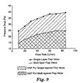
- a multi-layered flexible flap When mounted on a valve seat, a multi-layered flexible flap can provide a unidirectional fluid valve with a lower pressure drop.
- the pressure drop may be determined in accordance with the Pressure Drop Test set forth below.
- the pressure drop across the valve at a flow rate of 85 liters per minute (L/min), may be less than about 50 Pascals (Pa), and may be less than 40 Pa, and still may be less than 30 Pa.
- multi-layered flexible flaps may enable the inventive unidirectional fluid valve to have a pressure drop of less than 30 Pa, preferably less than 25 Pa , and more preferably less than 20 Pa.
- Pressure drops of about 5 to 50 Pa may be obtainable between flow rates of 10 L/min and 85 L/min using multi-layer flexible flaps in accordance with the present invention.
- the pressure drop may be less than 25 Pa over flow rates of 10 L/min to 85 L/min. If a flat valve seat is employed such as shown in FIG. 5, the pressure drop may be even less than 5 Pa at flow rates of 10 L/min.
- the flexible flap shown in FIGs. 7 and 8 represent flaps that have an AB, ABA, or ABA' construction. Flaps used in the present invention may also have an ABC construction, where B is the layer that is stiffer and has a greater modulus of elasticity. While resistance to curl can be best achieved when the flexible flap has symmetry around the stiffer B layer, as in an ABA construction, in some instances, it may be preferred to use a flexible flap that has an ABC construction, where layer B is stiffer and has a greater modulus of elasticity than layers A and C. Layer C may, however, be stiffer than layer B, if desired, and thus be the stiffest of the three layers and may comprise a material that has a modulus of elasticity that is greater than both layers A and B.
- Layers A and C may be made from different materials and may have a different modulus of elasticity with respect to each other. For example, layer A may have a greater modulus of elasticity than layer C, or vice versa.
- Multi-layered flaps could feasibly have a greater than 3, 4, or 5 and up to 10, 20, or 100 layers. Multi-layered flaps that have perhaps one thousand layers ABABAB...AB, ABA'...BABA'BABA', or ABC...ABCABC could also be useful in conjunction with the present invention.
- the layer that is the softer, more flexible (less stiff), and preferably has the lowest modulus of elasticity is disposed on the portion of the flexible flap that makes contact with the valve seat's seal surface.
- the inventors discovered that the use of a more flexible layer, and preferably a layer that has a lower modulus of elasticity, can allow a better seal to occur between the flexible flap and the seal surface under neutral conditions, that is, when a wearer is neither inhaling nor exhaling. It is therefore preferred ⁇ not only that the first layer of the flexible flap is disposed on the side of the flexible flap that faces the seal surface ⁇ but that the first layer directly contacts the seal surface when the flap is in the closed position.
- the flexible flap In addition to the primary layers of the flexible flap, namely layers AB, ABA, ABA', or ABC, there may be additional layers disposed between these layers in accordance with the present invention.
- primer layers or layers that assist in adhering the different layers together, may be present between the layers.
- protective coatings may be applied to the outer layers to address moisture or weathering issues.
- the softer, more flexible layer be in contact with the seal surface, which layer may have the lower modulus of elasticity
- there may be other layers such as the thin or thinner layers described above, that may be disposed between the first layer and the seal surface when the flap is resting on it. The presence of such layers, however, may be more or less incidental to the overall functioning of the flap.
- additional layers would not be as thick as layers A, A', B, and C, and typically would be substantially thinner such as, for example, 80%-99.9% thinner than the major layers A, A', B, and C.
- the exhalation valve that is described in U.S. Patents 5,325,892 and 5,509,436 to Japuntich et al. is believed to be a superior performing commercially available exhalation valve for use on a filtering face masks.
- Valves of the present invention may be capable of exceeding the performance criteria for leak rate, valve opening pressure drop, and pressure drop across the valve under various flow rates. These parameters may be measured using the Leak Rate Test and Pressure Drop Test described below.
- the Leak Rate is a parameter that measures the ability of the valve to remain closed under neutral conditions.
- the Leak Rate test is described below in detail but generally measures the amount of air that can pass through the valve at an air pressure differential of 1 inch water (249 Pa).
- Leak rates range from 0 to 30 cubic centimeters per minute (cm 3 /min) at 249 Pa pressure, with lower numbers indicating better sealing.
- leak rates that are less than or equal to 30 cm 3 /min can be achieved in accordance with the present invention.
- leak rates less than 10 cm 3 /min, more preferably less than 5 cm 3 /min may also be achieved.
- Exhalation valves that have been fashioned in accordance with the present invention may demonstrate a leak rate in the range of about 1 to 10 cm 3 /min.
- the valve opening pressure drop measures the resistance to the initial lifting of the flap from the valve's seal surface. This parameter may be determined as described below in the Pressure Drop Test.
- the valve opening pressure drop at 10 L/min is less than 30 Pa, preferably less than 25 Pa, and more preferably less than 20 Pa when testing a valve in accordance with the Pressure Drop Test described below.
- the valve opening pressure drop is about 5 to 30 Pa at 10 L/min when testing a valve in accordance with the Pressure Drop Test described below.
- Examples of materials from which the first layer of the flexible flap may be made include those that would promote a good seal between the flexible flap and the valve seat. These materials may generally include elastomers, both thermoset and thermoplastic, and thennoplastic/plastomers.
- Elastomers which may be either thermoplastic elastomers or crosslinked rubbers, may include rubber materials such as polyisoprene, poly (styrene-butadiene) rubber, polybutadiene, butyl rubber, ethylene-propylene-diene rubber, ethylene-propylene rubber, nitrile rubber, polychloroprene rubber, chlorinated polyethylene rubber, chlorosulphonated polyethylene rubber, polyacrylate elastomer, ethylene-acrylic rubber, fluorine containing elastomers, silicone rubber, polyurethane, epichlorohydrin rubber, propylene oxide rubber, polysulphide rubber, polyphosphazene rubber, and latex rubber, styrene-butadiene-styrene block copolymer elastomer, styrene-ethylene/butylene-styrene block copolymer elastomer, styrene-isoprene-styrene
- Examples of some commercially available polymeric materials that may be used for the first (or more flexible) layer of the flap include: Polymer Type Source Product Designator Published Elastic Modulus (MPa) Anhydride modified ethylene acrylate copolymer Dupont Packaging and Industrial Polymers, Wilmington, DE Bynel CXA 2174 Ethylene Vinyl Acetate Copolymer E. I.
- Elongations percentages were selected to best match the flattened portion of the stress-strain curve for a given material.
- Examples of materials from which the second stiffer layer of the flexible flap may be made include highly crystalline materials such as ceramics, diamond, glass, zirconia; metals/foils from materials such as boron, brass, magnesium alloys, nickel alloys, stainless steel, steel, titanium, and tungsten.
- Polymeric materials that may be suitable include thermoplastics such as copolyester ether, ethylene methyl acrylate polymer, polyurethane, acrylonitrile-butadiene styrene polymer, high density polyethylene, high impact polystyrene, linear low density polyethylene, polycarbonate, liquid crystal polymer, low density polyethylene, melamines, nylon, polyacrylate, polyamide-imide, polybutylene terephthalate, polycarbonate, polyetheretherketone, polyetherimide, polyethylene napthalene, polyethylene terephthalate, polyimide, polyoxymethylene, polypropylene, polystyrene, polyvinylidene chloride, and polyvinylidene fluoride.
- thermoplastics such as copolyester ether, ethylene methyl acrylate polymer, polyurethane, acrylonitrile-butadiene styrene polymer, high density polyethylene, high impact polystyrene, linear low density poly
- Naturally-derived cellulosic materials such as reed, paper, and woods like beech, cedar, maple, and spruce may also be useful. Blends, mixtures, and combinations of these materials may too be used, including blends with the polymers described as being useful in the more flexible A, A' layer(s). Although the same or similar polymeric materials may be used in both the A, A' and B layers, the polymeric materials may be processed differently or include other ingredients to create a difference in stiffness.
- Examples of some commercially available materials for the second stiffer layer include: Polymer Type Source Product Designator Published Elastic Modulus (MPa) Nylon 1l Elf Atochem, Philadelphia, PA Besno P40 TL 320 Nylon 1I Elf Atochem, Philadelphia, PA Besno TL 1300 Copolyester Ether Eastman Chemical Co., Kingsport, TN Ecdel 9966 110 Ethylene-Methyl Acrylate Copolymer Eastman Chemical Co., Kingsport, TN EMAC SP2220 Polycarbonate Bayer AG, Pittsburgh, PA Makrolon 3108 2413 Poly (ethylene terephthalate) E. I. Dupont Co., Wilmington, DE Mylar 50 CL 3790 Polypropylene Atofina, Deerpark, TX Polypropylene 3576
- all major layers A, A', B' and C in the flap are made from polymeric materials.
- polymeric means containing a polymer, which is a molecule that contains repeating units, regularly or irregularly arranged.
- the polymer may be natural or synthetic and preferably is organic.
- the third or C layer of the flexible flap may be made from materials that comprise any of the materials set forth above with respect to the first layer as long as they are substantially different from the materials used in the A layer.
- substantially in this context means that the layer has a significantly different stiffness from layer A, and preferably a different elastic modulus, which would cause the flap to perform noticeably different from a flap that had, for example, an ABA or an ABA' construction.
- simple variation in material morphology may be sufficient to provide the required mechanical dissimilarity between the layers A, B, A', and C.
- the multi-layer construction may or may not be continuous or uniform throughout the flexible flap; it may be present only in zones or vary in position within the flexible flap.
- the first layer A is in contact with the seal surface, it may only be juxtaposed on layer B in those areas where A makes contact with the seal surface.
- the A layer may be continuous whereas the B layer is discontinuous.
- the flexible flap thus may be fashioned in a variety of shapes and configurations.
- the flap could be circular, elliptical, rectangular, or a combination of such shapes, including, for example, the shapes shown in U.S. Patents 5,325,892 and 5,509,436 to Japuntich et al. and shown in U.S. Patent Application Serial Numbers 09/888,943 and 09/888,732 to Mittelstadt et al.
- the multi-layer construction may or may not have oriented layers, either in its entirety or in part.
- the B layer may be oriented with the A layers being unoriented.
- both the A and B layers may be oriented in the same direction or in different, cross, or opposing directions.
- Flexible flaps that are used in connection with the present invention may be made through a co-extrusion process where as few as two layers, or as many as a thousand layers, of material are extruded simultaneously to form a single sheet.
- the co-extrusion of two materials, in two or three layers, has been found to carry particular utility in forming flaps of the present invention. See U.S. Patent 3,557,265 to Chisholm et al. for an example of a method of extruding laminates.
- Other processes that could be utilized for manufacture of multi-layer flexible flaps or diaphragms may include controlled-depth cross linking with e-beam, electroplating, extrusion coating of a substrate, injection molding, lamination, solvent coating of a substrate, and vapor deposition onto a substrate.
- Example has been selected for presentation here merely to further illustrate particular features and details of the invention. It is to be expressly understood, however, that while the Example serves this purpose, the particular details, ingredients, and other features are not to be construed in a manner that would unduly limit the scope of this invention.
- Pressure drop testing is conducted on the valve with the aid of a flow fixture.
- the flow fixture provides air, at specified flow rates, to the valve through an aluminum mounting plate and an affixed air plenum.
- the mounting plate receives and securely holds a valve seat during testing.
- the aluminum mounting plate has a slight recess on its top surface that received the base of valve. Centered in the recess is a 28 millimeter (mm) by 34 mm opening through which air can flow to the valve.
- Adhesive-faced foam material may be attached to the ledge within the recess to provide an airtight seal between the valve and the plate. Two clamps are used to capture and secure the leading and rear edge of the valve seat to the aluminum mount.
- Air is provided to the mounting plate through a hemispherical-shaped plenum.
- the mounting plate is affixed to the plenum at the top or apex of the hemisphere to mimic the cavity shape and volume of a respiratory mask.
- the hemispherical-shaped plenum is approximately 30 mm deep and has a base diameter of 80 mm. Air from a supply line is attached to the base of the plenum and is regulated to provide the desired flow through the flow fixture to the valve. For an established air flow, air pressure within the plenum is measured to determine the pressure drop over the test valve.
- Pressure drop measurements are made on a test valve using the Flow Fixture as described above. Pressure drop across a valve was measured at flow rates of 10, 20, 30, 40, 50, 60, 70, and 85 liters per minute.
- a test specimen is mounted in the Flow Fixture so that the valve seat is horizontally oriented at its base, with the valve opening facing up. Care is taken during the valve mounting to assure that there is no air bypass between the fixture and the valve body.
- the flap is first removed from the valve body and the desired airflow is established. The pressure gauge is then set to zero, bringing the system to calibration.
- the flap is repositioned on the valve body and air, at the specified flow rate, is delivered to the inlet of the valve, and the pressure at the inlet is recorded.
- the valve-opening pressure drop (just before a zero-flow, flap opening onset point) is determined by measuring the pressure at the point where the flap just opens and a minimal flow is detected. Pressure drop is the difference between the inlet pressure to the valve and the ambient air.
- Leak rate testing for exhalation valves is generally as described in 42 CFR ⁇ 82.204. This leak rate test is suitable for valves that have a flexible flap mounted to the valve seat.
- the valve seat is sealed between the openings of two ported air chambers.
- the two air chambers are configured so that pressurized air that is introduced into the lower chamber flows up through the valve into the upper chamber.
- the lower air chamber is equipped so that their internal pressures can be monitored during testing.
- An air flow gauge is attached to the outlet port of the upper chamber to determine air flow through the chamber.
- the valve is sealed between the two chambers and is horizontally oriented with the flap facing the lower chamber.
- the lower chamber is pressurized via an air line to cause a pressure differential, between the two chambers, of 249 Pa (25mm H 2 O; 1 inch H 2 O). This pressure differential is maintained throughout the test procedure. Outflow of air from the upper chamber is recorded as the leak rate of the test valve. Leak rate is reported as the flow rate, in liters per minute, which results when an air pressure differential of 249 Pa is applied over the valve.
- the "actuation power" for a valve at a given flow rate can be determined for a range of flow rates by integrating the curve representing the flow rate (abscissa) in L/min and pressure drop (ordinate) in Pa, over a flow rate range of 10 to 85 L/min. Integration of the curve, represented graphically as the area under the curve, gives the power required to actuate a valve over a range of flows.
- the value for the integrated curve is defined as the Integrated Valve Activation Power (IVAP) in milliwatt (mW) units.
- VE is expressed in units of milliwatts•gram•cubic centimeters per minute or mW•g •cm 3 /min. Lower valve efficiency values represent better valve performance. Valves of the present invention may be able to achieve VE values of about 2 to 20 mW•g cm 3 /min, and more preferably less than about 10 mW•g cm 3 /min.
- a multi-layer polymer sheet was made from two resins that were formed into a three-layer ABA construction using a solvent coating process.
- the first and third layers of the sheet namely layers A and A, which provided outer major surface layers of the construction, were produced from an SBS(styrene-butadiene-styrene) rubber FinapreneTM 502 having an elastic modulus of 2 MPa supplied by Atofina Company, Houston, Texas blended with 1 % by weight AtmerTM 1759 supplied by Ciba Geigy, 540 White Plains, NY 10591.
- the second middle layer B was a 36 micrometer thick polyester (PET) sheet that had an elastic modulus of 3790 MPa supplied by 3M Company.
- a 0.3 meter wide sheet of 36 micrometer thick polyester was coated on one side with the FinapreneTM 502 solution to a final dried thickness of 13 micrometers and 0.279 meters in width via a HiranoTM M-200L notch bar coater set to a gap of 89 micrometers.
- a line speed of 1 meter/min was employed so that the residence time of the coated film was 3 minutes in the 3 meter long oven, to ensure that the coating completely dried.
- Static charge was controlled via static strings at each idler roll on the coater as well as a deionizing bar just before the notched bar.
- the wound sheet, with one side coated was flipped over and was run through the same coating procedure just described to provide the final layer and a resultant three layer sheet that had a total thickness of 62 micrometers.
- Flexible flaps were formed from the symmetrical ABA sheet by die cutting the multi-layer sheet to create a rectangular portion that had a semi-circular end (see FIG. 1, item 22).
- Table 3 The structural configuration of the flap is summarized in Table 3 below: Layer Thickness ( ⁇ m) Total Flap Thickness ( ⁇ m) Flap Length (cm) Flap Width (cm) Radius of Semicircular end (cm) A B 13 36 62 3.25 2.4 1.2
- the rectangular end of the flap was secured to a valve seat in a valve body.
- the valve body had a valve seat that had a concave curvature when viewed from a side elevation.
- valve seat The configuration of the valve seat is described generally in U.S. Patents 5,325,892 and 5,509,436 to Japuntich et al. and is used in a valve body employed in a commercially available face mask, model 8511, available from 3M Company, St. Paul, MN.
- the valve body had circular orifice of 3.3 square centimeters (cm 2 ) disposed within the valve seat.
- the valve flap was clamped to a flap-retaining surface that was about 4 millimeters (mm) long and that traversed the valve seat for a distance of about 25 mm.
- the curved seal ridge had a width of about 0.51 mm.
- the flexible flap remained in an abutting relationship to the seal ridge under neutral conditions, no matter how the valve was oriented. No valve cover was attached to the valve seat.
- a FinapreneTM 502 sheet that contained 1% Atmer 1759 was prepared in exactly the same way as given in example one with the exception that this solution was coated onto a silicone release liner. Strips of 23.4 micrometer thick PET film were cut 0.794 cm wide. Likewise strips of the FinapreneTM 502 coated liner were cut 0.794 cm wide, with the liner included to facilitate cutting. Upon separating the FinapreneTM 502 film from the release liner, the film thickness measured was 24 micrometers thick, very close to the thickness of the PET.
- a cantilever bending test was used to indicate stiffness of thin strips of material by measuring the bending length of a specimen under its own mass.
- a test specimen was prepared by cutting the 0.794 cm wide strips of material to approximately 5 cm lengths. The specimen was slid, in a direction parallel to its long dimension, over the 90° edge of a horizontal surface. After 1.5 cm of material was extended past the edge, the overhang of the specimen was measured as the vertical distance from the end of the strip to the horizontal surface. The overhanging distance of the specimen divided by its extended length was reported as the cantilever bend ratio.
- a cantilever bend ratio approaching 1 would indicate a high level of flexibility where a material with a bend ratio approaching 0 would be stiff.
- a valve, with its outer protective cover removed, from a commercially available 8511TM N95 respirator available from 3M Company, St. Paul, Minnesota was evaluated using the test procedures described above.
- the valve seat that was used was the same as the valve seat used in Example 1.
- the flexible flap had a monolithic construction, which was the same as the flaps used in the commercially available 8511TM 3M mask.
- the flap was composed of polyisoprene.
- the flexible flap had the same dimensions as the flap used in Example 1 and had a material density of 1.08 grams per cubic centimeter (g/cm 3 ).
- valve or face mask that employs the inventive technology requires significantly less (37% less) power to actuate, when compared to a face mask that uses a valve that has a single layered construction, over a functional range of flow rates.
- a reduction in valve actuation power is important in use because the wearer's breathing is what actuates the valve. The greater the actuation power, especially over the functional range of the valve, the more difficult it is for the wearer to breathe when the mask is worn.
- a mask that is more easily vented, through a valve that requires less power to actuate, is more efficient in removing carbon dioxide and moisture, which further improves wearer comfort and makes it more likely that the wearer will keep the mask donned to their face when in a toxic environment.
- the data set forth in Table 5 also demonstrate that the invention may afford a 850% Valve Efficiency improvement over a comparative valve when operating in the functional range typical for filtering face masks.
- Valve Efficiency parameter accounts for the counter balancing effects of leakage, valve mass, and actuation power, this is a particularly significant result.
- a valve designed for use with a face mask that employs a single layer material construction may require, when considered on an equivalent design basis, a heavier flap to more tightly close the valve.
- a flap that has a tighter seal and greater mass requires more power to actuate.
- the required increase in mass and actuation power offsets any efficiency gains for reduced leak rate.
Landscapes
- Health & Medical Sciences (AREA)
- Pulmonology (AREA)
- General Health & Medical Sciences (AREA)
- Business, Economics & Management (AREA)
- Emergency Management (AREA)
- Respiratory Apparatuses And Protective Means (AREA)
- Check Valves (AREA)
Applications Claiming Priority (3)
| Application Number | Priority Date | Filing Date | Title |
|---|---|---|---|
| US09/989,965 US7028689B2 (en) | 2001-11-21 | 2001-11-21 | Filtering face mask that uses an exhalation valve that has a multi-layered flexible flap |
| US989965 | 2001-11-21 | ||
| PCT/US2002/031418 WO2003045503A1 (en) | 2001-11-21 | 2002-10-03 | Filtering face mask that uses an exhalation valve that has a multilayered flexible flap |
Publications (2)
| Publication Number | Publication Date |
|---|---|
| EP1446197A1 EP1446197A1 (en) | 2004-08-18 |
| EP1446197B1 true EP1446197B1 (en) | 2005-06-29 |
Family
ID=25535618
Family Applications (1)
| Application Number | Title | Priority Date | Filing Date |
|---|---|---|---|
| EP02778420A Expired - Lifetime EP1446197B1 (en) | 2001-11-21 | 2002-10-03 | Filtering face mask that uses an exhalation valve that has a multilayered flexible flap |
Country Status (14)
| Country | Link |
|---|---|
| US (2) | US7028689B2 (enExample) |
| EP (1) | EP1446197B1 (enExample) |
| JP (1) | JP4386728B2 (enExample) |
| KR (1) | KR100913855B1 (enExample) |
| CN (1) | CN100522288C (enExample) |
| AT (1) | ATE298607T1 (enExample) |
| AU (1) | AU2002340081B2 (enExample) |
| BR (1) | BR0213882A (enExample) |
| CA (1) | CA2466481A1 (enExample) |
| DE (1) | DE60204909T2 (enExample) |
| ES (1) | ES2242884T3 (enExample) |
| MX (1) | MXPA04004761A (enExample) |
| TW (1) | TWI238729B (enExample) |
| WO (1) | WO2003045503A1 (enExample) |
Cited By (1)
| Publication number | Priority date | Publication date | Assignee | Title |
|---|---|---|---|---|
| TWI747675B (zh) * | 2020-12-21 | 2021-11-21 | 林平陞 | 一種口罩結構 |
Families Citing this family (111)
| Publication number | Priority date | Publication date | Assignee | Title |
|---|---|---|---|---|
| US20030168063A1 (en) * | 2002-03-08 | 2003-09-11 | Gambone Anthony Joseph | Pressure face mask and nasal mask |
| USD567365S1 (en) * | 2003-04-25 | 2008-04-22 | Louis M. Gerson Co., Inc. | Pleated face mask |
| DE10327994B4 (de) * | 2003-06-02 | 2006-05-18 | BLüCHER GMBH | Kapuze für Schutzbekleidung und Bekleidungsstück mit Kapuze |
| US7188622B2 (en) * | 2003-06-19 | 2007-03-13 | 3M Innovative Properties Company | Filtering face mask that has a resilient seal surface in its exhalation valve |
| SG115600A1 (en) | 2003-12-31 | 2005-10-28 | Megatech Scientific Pte Ltd | Respiratory mask with inserted spacer |
| US20060005838A1 (en) * | 2004-07-07 | 2006-01-12 | Mark Magidson | Multi-layer face mask with foamed in place edge member |
| USD567937S1 (en) * | 2004-07-16 | 2008-04-29 | Louis M. Gerson Co., Inc. | Pleated face mask |
| DE102005024729B3 (de) * | 2005-05-31 | 2006-09-28 | Dräger Safety AG & Co. KGaA | Atemmaske |
| EP1741464A3 (en) * | 2005-07-07 | 2007-04-25 | Bristol-Myers Squibb Company | One-way valve for an inflatable chamber of a medical device |
| US7587929B2 (en) * | 2005-09-09 | 2009-09-15 | Scot Incorporated | Joint combined aircrew systems tester |
| US7503326B2 (en) * | 2005-12-22 | 2009-03-17 | 3M Innovative Properties Company | Filtering face mask with a unidirectional valve having a stiff unbiased flexible flap |
| FI20065120A0 (fi) * | 2006-02-17 | 2006-02-17 | Euromaski Oy | Suojalaite |
| US20100224199A1 (en) * | 2006-05-01 | 2010-09-09 | Kimberly-Clark Worldwide, Inc. | Respirator |
| US20080178884A1 (en) * | 2007-01-25 | 2008-07-31 | Gerson Ronald L | Fluid Valve with Center Post |
| US20080271740A1 (en) | 2007-05-03 | 2008-11-06 | 3M Innovative Properties Company | Maintenance-free flat-fold respirator that includes a graspable tab |
| US9770611B2 (en) * | 2007-05-03 | 2017-09-26 | 3M Innovative Properties Company | Maintenance-free anti-fog respirator |
| US20080271739A1 (en) | 2007-05-03 | 2008-11-06 | 3M Innovative Properties Company | Maintenance-free respirator that has concave portions on opposing sides of mask top section |
| US20090000624A1 (en) * | 2007-06-28 | 2009-01-01 | 3M Innovative Properties Company | Respirator having a harness and methods of making and fitting the same |
| US9642403B2 (en) * | 2007-08-16 | 2017-05-09 | Kimberly-Clark Worldwide, Inc. | Strap fastening system for a disposable respirator providing improved donning |
| JP4891877B2 (ja) * | 2007-09-14 | 2012-03-07 | 花王株式会社 | マスク |
| MX2010002886A (es) * | 2007-09-20 | 2010-03-30 | 3M Innovative Properties Co | Respirador de pieza facial filtrante que tiene armazon para soportar valvula de exhalacion. |
| WO2009038904A1 (en) | 2007-09-20 | 2009-03-26 | 3M Innovative Properties Company | Filtering face-piece respirator that has expandable mask body |
| KR20100105624A (ko) | 2007-11-27 | 2010-09-29 | 쓰리엠 이노베이티브 프로퍼티즈 컴파니 | 일방향 밸브를 구비한 안면 마스크 |
| PT2222908E (pt) * | 2007-12-06 | 2013-03-28 | 3M Innovative Properties Co | Tecidos de eletretos com aditivos que intensificam as cargas |
| KR200446949Y1 (ko) * | 2008-02-04 | 2009-12-17 | 주식회사 모아세이프 | 배기밸브 및 이를 구비한 마스크 |
| DE102008010475A1 (de) * | 2008-02-21 | 2009-08-27 | Seleon Gmbh | Applikatoren für eine Luftbrille |
| US20090235934A1 (en) * | 2008-03-24 | 2009-09-24 | 3M Innovative Properties Company | Filtering face-piece respirator having an integrally-joined exhalation valve |
| JP5072708B2 (ja) * | 2008-05-15 | 2012-11-14 | ユニ・チャーム株式会社 | マスク |
| WO2009148747A2 (en) * | 2008-06-02 | 2009-12-10 | 3M Innovative Properties Company | Charge-enhancing additives for electrets |
| BRPI0909959B1 (pt) * | 2008-06-02 | 2018-11-13 | 3M Innovative Properties Co | manta de eletreto e meio de filtro à base de eletreto |
| US7765698B2 (en) * | 2008-06-02 | 2010-08-03 | 3M Innovative Properties Company | Method of making electret articles based on zeta potential |
| FR2935272B1 (fr) * | 2008-08-26 | 2010-09-03 | Deltalyo & Valmy | Composition multicouche pour masque respiratoire |
| KR100912233B1 (ko) * | 2008-12-12 | 2009-08-14 | (주)피앤티디 | 마스크 |
| US11083916B2 (en) | 2008-12-18 | 2021-08-10 | 3M Innovative Properties Company | Flat fold respirator having flanges disposed on the mask body |
| JP2012513808A (ja) * | 2008-12-30 | 2012-06-21 | コーニンクレッカ フィリップス エレクトロニクス エヌ ヴィ | マスク及び治療用の呼吸に適した物質を供給する方法。 |
| AU2009334356A1 (en) * | 2008-12-30 | 2011-08-18 | Koninklijke Philips Electronics, N.V. | Mask and method for delivering a therapeutic breathable substance |
| US20100252047A1 (en) | 2009-04-03 | 2010-10-07 | Kirk Seth M | Remote fluorination of fibrous filter webs |
| ITPD20090117A1 (it) * | 2009-05-04 | 2010-11-05 | Euroflex Srl | Spruzzatore a mano per liquidi detergenti |
| PL2461857T3 (pl) * | 2009-08-07 | 2020-01-31 | Kind Consumer Limited | Inhalator |
| US8640704B2 (en) | 2009-09-18 | 2014-02-04 | 3M Innovative Properties Company | Flat-fold filtering face-piece respirator having structural weld pattern |
| US8881729B2 (en) | 2009-09-18 | 2014-11-11 | 3M Innovative Properties Company | Horizontal flat-fold filtering face-piece respirator having indicia of symmetry |
| AU2010224323A1 (en) | 2009-09-18 | 2011-04-07 | 3M Innovative Properties Company | Filtering face respirator having grasping feature indicator |
| USD657053S1 (en) * | 2009-09-22 | 2012-04-03 | World Wide Welding, Inc. | Dust mask |
| USD657052S1 (en) * | 2009-09-22 | 2012-04-03 | World Wide Welding, Inc. | Dust mask |
| US8528560B2 (en) | 2009-10-23 | 2013-09-10 | 3M Innovative Properties Company | Filtering face-piece respirator having parallel line weld pattern in mask body |
| US8365771B2 (en) | 2009-12-16 | 2013-02-05 | 3M Innovative Properties Company | Unidirectional valves and filtering face masks comprising unidirectional valves |
| USD676527S1 (en) | 2009-12-16 | 2013-02-19 | 3M Innovative Properties Company | Unidirectional valve |
| WO2011090586A2 (en) | 2009-12-30 | 2011-07-28 | 3M Innovative Properties Company | Filtering face-piece respirator having an auxetic mesh in the mask body |
| JP5445343B2 (ja) * | 2010-06-11 | 2014-03-19 | 株式会社デンソー | 水蒸気バルブ |
| JP5212432B2 (ja) * | 2010-07-16 | 2013-06-19 | 株式会社デンソー | リードバルブ |
| US20120017911A1 (en) | 2010-07-26 | 2012-01-26 | 3M Innovative Properties Company | Filtering face-piece respirator having foam shaping layer |
| US20120125341A1 (en) | 2010-11-19 | 2012-05-24 | 3M Innovative Properties Company | Filtering face-piece respirator having an overmolded face seal |
| RU2013126925A (ru) * | 2010-12-29 | 2015-02-10 | Зм Инновейтив Пропертиз Компани | Клапан, содержащий аблированную створку |
| US20120167890A1 (en) * | 2010-12-29 | 2012-07-05 | 3M Innovative Properties Company | Respirator having valve with an ablated flap |
| US20120247474A1 (en) * | 2011-03-29 | 2012-10-04 | Steve Gordon Torbenson | Face mask apparatus and system |
| GB201106479D0 (en) * | 2011-04-18 | 2011-06-01 | Draeger Safety Uk Ltd | Diaphragm |
| US20140182600A1 (en) | 2012-12-27 | 2014-07-03 | 3M Innovative Properties Company | Filtering face-piece respirator having welded indicia hidden in pleat |
| US11116998B2 (en) | 2012-12-27 | 2021-09-14 | 3M Innovative Properties Company | Filtering face-piece respirator having folded flange |
| US10182603B2 (en) | 2012-12-27 | 2019-01-22 | 3M Innovative Properties Company | Filtering face-piece respirator having strap-activated folded flange |
| US9259058B2 (en) | 2013-02-01 | 2016-02-16 | 3M Innovative Properties Company | Personal protective equipment strap retaining devices |
| US9247788B2 (en) | 2013-02-01 | 2016-02-02 | 3M Innovative Properties Company | Personal protective equipment strap retaining devices |
| EP2805749B1 (en) * | 2013-05-22 | 2019-12-25 | Moldex-Metric AG & Co. KG | Breathing mask |
| USD746974S1 (en) | 2013-07-15 | 2016-01-05 | 3M Innovative Properties Company | Exhalation valve flap |
| CA2917504C (en) | 2013-07-15 | 2022-06-21 | 3M Innovative Properties Company | Respirator having optically active exhalation valve |
| JP6223140B2 (ja) * | 2013-11-15 | 2017-11-01 | 興研株式会社 | 使い捨てマスク |
| CN105722558B (zh) | 2013-11-15 | 2019-06-07 | 3M创新有限公司 | 具有非圆形的质心安装的呼气阀的呼吸器 |
| FR3014413B1 (fr) * | 2013-12-05 | 2018-04-20 | Airbus Operations | Dispositif d'ejection d'air comprenant un profil aerodynamique muni d'une languette flexible d'obturation de fente |
| USD746439S1 (en) | 2013-12-30 | 2015-12-29 | Kimberly-Clark Worldwide, Inc. | Combination valve and buckle set for disposable respirators |
| JP2017512263A (ja) | 2014-02-27 | 2017-05-18 | スリーエム イノベイティブ プロパティズ カンパニー | 透かし細工構造を有する弾性ストラップを備えた呼吸マスク |
| US10040621B2 (en) | 2014-03-20 | 2018-08-07 | 3M Innovative Properties Company | Filtering face-piece respirator dispenser |
| CN104083833B (zh) * | 2014-08-02 | 2017-04-12 | 陆洪林 | 一种防尘面罩 |
| JP2017525862A (ja) | 2014-08-18 | 2017-09-07 | スリーエム イノベイティブ プロパティズ カンパニー | ポリマーネットを含むレスピレータ及びポリマーネットを含むレスピレータを形成する方法 |
| US11554471B2 (en) * | 2014-08-28 | 2023-01-17 | Power Tech Staple and Nail, Inc. | Elastomeric exhaust reed valve for combustion driven fastener hand tool |
| GB201421618D0 (en) | 2014-12-04 | 2015-01-21 | 3M Innovative Properties Co | Respirator valve |
| FR3029403B1 (fr) * | 2014-12-05 | 2016-11-25 | Salomon Sas | Masque avec element de confort |
| GB201508114D0 (en) | 2015-05-12 | 2015-06-24 | 3M Innovative Properties Co | Respirator tab |
| US10434341B1 (en) | 2015-06-05 | 2019-10-08 | Steve Gordon Torbenson | Mask apparatuses and approach |
| RU2015141569A (ru) | 2015-09-30 | 2017-04-05 | 3М Инновейтив Пропертиз Компани | Складной респиратор с лицевой маской и клапаном выдоха |
| WO2017066284A1 (en) | 2015-10-12 | 2017-04-20 | 3M Innovative Properties Company | Filtering face-piece respirator including functional material and method of forming same |
| WO2017065853A1 (en) * | 2015-10-16 | 2017-04-20 | Yang Song | Particulate filter face mask having fan breathing assist |
| US11213080B2 (en) | 2015-11-11 | 2022-01-04 | 3M Innovative Properties Company | Shape retaining flat-fold respirator |
| GB201609168D0 (en) | 2016-05-25 | 2016-07-06 | 3M Innovative Properties Co | Exhaust valve shroud for a personal protection respiratory device |
| USD900306S1 (en) | 2016-09-16 | 2020-10-27 | 3M Innovative Properties Company | Valve cover |
| USD828546S1 (en) | 2016-09-16 | 2018-09-11 | 3M Innovative Properties Company | Valve cover with openings |
| USD827811S1 (en) | 2016-09-16 | 2018-09-04 | 3M Innovative Properties Company | Valve cover |
| USD849245S1 (en) | 2016-09-16 | 2019-05-21 | 3M Innovative Properties Company | Valve cover |
| USD827812S1 (en) | 2016-09-16 | 2018-09-04 | 3M Innovative Properties Company | Valve cover with openings |
| USD842983S1 (en) | 2016-09-16 | 2019-03-12 | 3M Innovative Properties Company | Valve cover |
| USD843562S1 (en) | 2016-09-16 | 2019-03-19 | 3M Innovative Properties Company | Valve cover with diamond pattern |
| USD882758S1 (en) | 2016-09-16 | 2020-04-28 | 3M Innovative Properties Company | Valve cover |
| CN109715252B (zh) * | 2016-09-16 | 2021-10-19 | 3M创新有限公司 | 呼气阀和包括呼气阀的呼吸器 |
| WO2018081227A1 (en) | 2016-10-28 | 2018-05-03 | 3M Innovative Properties Company | Respirator including reinforcing element |
| CN106390319A (zh) * | 2016-10-31 | 2017-02-15 | 山西新华化工有限责任公司 | 全脸式单罐综合防护面具 |
| WO2019012399A1 (en) | 2017-07-14 | 2019-01-17 | 3M Innovative Properties Company | ADAPTER FOR TRANSPORTING MULTIPLE FLOWS OF LIQUID |
| JP6866042B2 (ja) * | 2017-09-27 | 2021-04-28 | 信越化学工業株式会社 | 液体の吐出方法 |
| WO2019135150A1 (en) | 2018-01-03 | 2019-07-11 | 3M Innovative Properties Company | Respirator including transversely-extending pleat and method of forming same |
| WO2019243116A1 (en) | 2018-06-22 | 2019-12-26 | Koninklijke Philips N.V. | Patient interface valve arrangement |
| CN109681679B (zh) * | 2019-02-26 | 2024-07-09 | 昆山远山天地软件技术有限公司 | 流体单向导通结构、止回组件及呼吸设备 |
| WO2020243321A1 (en) * | 2019-05-28 | 2020-12-03 | Delstar Technologies, Inc. | Pleated polymeric sheet having apertures |
| JPWO2021117722A1 (enExample) * | 2019-12-12 | 2021-06-17 | ||
| US12017232B2 (en) | 2020-03-13 | 2024-06-25 | Julian HENLEY | Electro-ionic mask devices for improved protection from airborne biopathogens |
| EP4118385A4 (en) | 2020-03-13 | 2024-04-24 | Henley, Julian | ELECTRO-IONIC DEVICES FOR IMPROVED PROTECTION AGAINST AIR-SUSPENDED BIOPATHOGENS |
| DE102020107746A1 (de) | 2020-03-20 | 2021-09-23 | Solvamed Gmbh | Verbesserte Atemschutzmaske |
| JP6850385B1 (ja) * | 2020-04-06 | 2021-03-31 | 良政 田口 | 鼻咽頭検体採取時に用いる感染防止袋 |
| KR102578853B1 (ko) * | 2020-05-21 | 2023-09-14 | 김준기 | 마스크 |
| WO2021252326A1 (en) * | 2020-06-08 | 2021-12-16 | Thermopore Materials Corporation | Face masks and methods of producing same |
| US11998777B2 (en) | 2020-07-27 | 2024-06-04 | Auburn University | Serviceable respirator system with configurable components |
| US20230117086A1 (en) * | 2021-10-19 | 2023-04-20 | Rex Carroll | Face mask in a cup shape with sticky micro droplets sprayed between its synthetic mesh layers |
| CN115255351B (zh) * | 2022-07-12 | 2023-09-15 | 中南大学 | 金刚石-金属基三维成型复合材料、丝材及其制备和在fdm打印中的应用 |
| US20240115889A1 (en) | 2022-10-07 | 2024-04-11 | 3M Innovative Properties Company | Disposable, Flat-Fold Respirator Having Increased Stiffness in Selected Areas |
| WO2025202974A1 (en) | 2024-03-29 | 2025-10-02 | 3M Innovative Properties Company | Respirators, respirator materials and methods of manufacturing the same |
Family Cites Families (24)
| Publication number | Priority date | Publication date | Assignee | Title |
|---|---|---|---|---|
| US2072516A (en) | 1934-02-08 | 1937-03-02 | American Mach & Foundry | Insert attachment for wrapping machines |
| GB504232A (en) * | 1937-07-17 | 1939-04-21 | Int Latex Processes Ltd | Improvements in or relating to rubber gas masks |
| US2230770A (en) | 1939-12-09 | 1941-02-04 | Cons Car Heating Co Inc | Circuit controller |
| US2895472A (en) * | 1956-01-05 | 1959-07-21 | Electric Storage Battery Co | Respirator |
| US3557265A (en) | 1967-12-29 | 1971-01-19 | Dow Chemical Co | Method of extruding laminates |
| US3994319A (en) * | 1973-05-24 | 1976-11-30 | Skyline Industries, Inc. | Reed type valve formed of high modulus fiber reinforced composite material |
| US3983900A (en) * | 1975-12-09 | 1976-10-05 | Airhart Tom P | Reed valves formed of high modulus fiber reinforced resin |
| DE2852016A1 (de) | 1978-12-01 | 1980-06-04 | Draegerwerk Ag | Membran fuer atemgesteuertes dosierventil |
| US4630604A (en) | 1985-04-09 | 1986-12-23 | Siebe North, Inc. | Valve assembly for a replaceable filter respirator |
| US4934362A (en) | 1987-03-26 | 1990-06-19 | Minnesota Mining And Manufacturing Company | Unidirectional fluid valve |
| FR2641597B1 (fr) | 1989-01-11 | 1991-04-26 | Enjalric Raoul | Clapet antiretour pour combinaison de protection |
| US5285816A (en) * | 1991-12-11 | 1994-02-15 | Rapid Developments Ltd. | One way valve |
| FR2688287B1 (fr) | 1992-03-03 | 1994-07-01 | Enjalric Raoul | Clapet anti-retour a double sortie pour combinaison de protection. |
| US5325892A (en) * | 1992-05-29 | 1994-07-05 | Minnesota Mining And Manufacturing Company | Unidirectional fluid valve |
| CA2134764C (en) | 1992-05-29 | 1999-04-27 | Daniel A. Japuntich | Unidirectional fluid valve |
| IL105562A (en) | 1993-04-30 | 1998-09-24 | Raphael Valves Ind 1975 Ltd | Diaphragm for valves |
| US5355910A (en) * | 1993-10-13 | 1994-10-18 | Trw Inc. | Dual component flap |
| JPH0910343A (ja) * | 1995-06-30 | 1997-01-14 | Shigematsu Seisakusho:Kk | 吸気弁 |
| GB9515986D0 (en) | 1995-08-04 | 1995-10-04 | Racal Health & Safety Ltd | Uni-directional fluid valve |
| US6584976B2 (en) * | 1998-07-24 | 2003-07-01 | 3M Innovative Properties Company | Face mask that has a filtered exhalation valve |
| US6047698A (en) | 1998-08-20 | 2000-04-11 | Moldex-Metric, Inc. | Unidirectional fluid valve |
| US6210266B1 (en) * | 1999-03-15 | 2001-04-03 | Sarnamotive Blue Water, Inc. | Pressure relief valve and method of manufacturing the same |
| US6883518B2 (en) * | 2001-06-25 | 2005-04-26 | 3M Innovative Properties Company | Unidirectional respirator valve |
| US7849856B2 (en) * | 2001-06-25 | 2010-12-14 | 3M Innovative Properties Company | Respirator valve |
-
2001
- 2001-11-21 US US09/989,965 patent/US7028689B2/en not_active Expired - Lifetime
-
2002
- 2002-10-03 ES ES02778420T patent/ES2242884T3/es not_active Expired - Lifetime
- 2002-10-03 WO PCT/US2002/031418 patent/WO2003045503A1/en not_active Ceased
- 2002-10-03 CA CA002466481A patent/CA2466481A1/en not_active Abandoned
- 2002-10-03 KR KR1020047007667A patent/KR100913855B1/ko not_active Expired - Fee Related
- 2002-10-03 BR BR0213882-4A patent/BR0213882A/pt not_active Application Discontinuation
- 2002-10-03 DE DE60204909T patent/DE60204909T2/de not_active Expired - Lifetime
- 2002-10-03 MX MXPA04004761A patent/MXPA04004761A/es active IP Right Grant
- 2002-10-03 AT AT02778420T patent/ATE298607T1/de not_active IP Right Cessation
- 2002-10-03 AU AU2002340081A patent/AU2002340081B2/en not_active Ceased
- 2002-10-03 EP EP02778420A patent/EP1446197B1/en not_active Expired - Lifetime
- 2002-10-03 CN CNB028229193A patent/CN100522288C/zh not_active Expired - Fee Related
- 2002-10-03 JP JP2003546999A patent/JP4386728B2/ja not_active Expired - Fee Related
- 2002-10-31 TW TW091132269A patent/TWI238729B/zh not_active IP Right Cessation
-
2005
- 2005-01-21 US US11/041,044 patent/US7013895B2/en not_active Expired - Lifetime
Cited By (1)
| Publication number | Priority date | Publication date | Assignee | Title |
|---|---|---|---|---|
| TWI747675B (zh) * | 2020-12-21 | 2021-11-21 | 林平陞 | 一種口罩結構 |
Also Published As
| Publication number | Publication date |
|---|---|
| US20050155607A1 (en) | 2005-07-21 |
| KR20040053350A (ko) | 2004-06-23 |
| TW200300355A (en) | 2003-06-01 |
| MXPA04004761A (es) | 2004-07-30 |
| BR0213882A (pt) | 2004-08-31 |
| US7028689B2 (en) | 2006-04-18 |
| US7013895B2 (en) | 2006-03-21 |
| CA2466481A1 (en) | 2003-06-05 |
| CN1589168A (zh) | 2005-03-02 |
| DE60204909D1 (de) | 2005-08-04 |
| AU2002340081A1 (en) | 2003-06-10 |
| EP1446197A1 (en) | 2004-08-18 |
| TWI238729B (en) | 2005-09-01 |
| JP4386728B2 (ja) | 2009-12-16 |
| ATE298607T1 (de) | 2005-07-15 |
| AU2002340081B2 (en) | 2008-04-10 |
| DE60204909T2 (de) | 2006-04-27 |
| WO2003045503A1 (en) | 2003-06-05 |
| ES2242884T3 (es) | 2005-11-16 |
| JP2005510314A (ja) | 2005-04-21 |
| KR100913855B1 (ko) | 2009-08-26 |
| CN100522288C (zh) | 2009-08-05 |
| US20050061327A1 (en) | 2005-03-24 |
Similar Documents
| Publication | Publication Date | Title |
|---|---|---|
| EP1446197B1 (en) | Filtering face mask that uses an exhalation valve that has a multilayered flexible flap | |
| EP1962964B1 (en) | Filtering face mask with a unidirectional valve having a stiff unbiased flexible flap | |
| KR101121859B1 (ko) | 배출 밸브 내에 탄성 시일 표면을 갖는 여과 안면 마스크 | |
| US20240416157A1 (en) | Exhalation valve and respirator including same | |
| EP2217334B1 (en) | Face mask with unidirectional valve | |
| US20120168658A1 (en) | Valve having an ablated flap | |
| EP2658593A1 (en) | Respirator having valve with an ablated flap |
Legal Events
| Date | Code | Title | Description |
|---|---|---|---|
| PUAI | Public reference made under article 153(3) epc to a published international application that has entered the european phase |
Free format text: ORIGINAL CODE: 0009012 |
|
| 17P | Request for examination filed |
Effective date: 20040526 |
|
| AK | Designated contracting states |
Kind code of ref document: A1 Designated state(s): AT BE BG CH CY CZ DE DK EE ES FI FR GB GR IE IT LI LU MC NL PT SE SK TR |
|
| AX | Request for extension of the european patent |
Extension state: AL LT LV MK RO SI |
|
| GRAP | Despatch of communication of intention to grant a patent |
Free format text: ORIGINAL CODE: EPIDOSNIGR1 |
|
| GRAS | Grant fee paid |
Free format text: ORIGINAL CODE: EPIDOSNIGR3 |
|
| GRAA | (expected) grant |
Free format text: ORIGINAL CODE: 0009210 |
|
| AK | Designated contracting states |
Kind code of ref document: B1 Designated state(s): AT BE BG CH CY CZ DE DK EE ES FI FR GB GR IE IT LI LU MC NL PT SE SK TR |
|
| PG25 | Lapsed in a contracting state [announced via postgrant information from national office to epo] |
Ref country code: AT Free format text: LAPSE BECAUSE OF FAILURE TO SUBMIT A TRANSLATION OF THE DESCRIPTION OR TO PAY THE FEE WITHIN THE PRESCRIBED TIME-LIMIT Effective date: 20050629 Ref country code: CH Free format text: LAPSE BECAUSE OF FAILURE TO SUBMIT A TRANSLATION OF THE DESCRIPTION OR TO PAY THE FEE WITHIN THE PRESCRIBED TIME-LIMIT Effective date: 20050629 Ref country code: SK Free format text: LAPSE BECAUSE OF FAILURE TO SUBMIT A TRANSLATION OF THE DESCRIPTION OR TO PAY THE FEE WITHIN THE PRESCRIBED TIME-LIMIT Effective date: 20050629 Ref country code: LI Free format text: LAPSE BECAUSE OF FAILURE TO SUBMIT A TRANSLATION OF THE DESCRIPTION OR TO PAY THE FEE WITHIN THE PRESCRIBED TIME-LIMIT Effective date: 20050629 Ref country code: EE Free format text: LAPSE BECAUSE OF FAILURE TO SUBMIT A TRANSLATION OF THE DESCRIPTION OR TO PAY THE FEE WITHIN THE PRESCRIBED TIME-LIMIT Effective date: 20050629 Ref country code: FI Free format text: LAPSE BECAUSE OF FAILURE TO SUBMIT A TRANSLATION OF THE DESCRIPTION OR TO PAY THE FEE WITHIN THE PRESCRIBED TIME-LIMIT Effective date: 20050629 Ref country code: CZ Free format text: LAPSE BECAUSE OF FAILURE TO SUBMIT A TRANSLATION OF THE DESCRIPTION OR TO PAY THE FEE WITHIN THE PRESCRIBED TIME-LIMIT Effective date: 20050629 |
|
| REG | Reference to a national code |
Ref country code: GB Ref legal event code: FG4D |
|
| REG | Reference to a national code |
Ref country code: CH Ref legal event code: EP |
|
| REF | Corresponds to: |
Ref document number: 60204909 Country of ref document: DE Date of ref document: 20050804 Kind code of ref document: P |
|
| REG | Reference to a national code |
Ref country code: IE Ref legal event code: FG4D |
|
| PG25 | Lapsed in a contracting state [announced via postgrant information from national office to epo] |
Ref country code: DK Free format text: LAPSE BECAUSE OF FAILURE TO SUBMIT A TRANSLATION OF THE DESCRIPTION OR TO PAY THE FEE WITHIN THE PRESCRIBED TIME-LIMIT Effective date: 20050929 Ref country code: BG Free format text: LAPSE BECAUSE OF FAILURE TO SUBMIT A TRANSLATION OF THE DESCRIPTION OR TO PAY THE FEE WITHIN THE PRESCRIBED TIME-LIMIT Effective date: 20050929 Ref country code: GR Free format text: LAPSE BECAUSE OF FAILURE TO SUBMIT A TRANSLATION OF THE DESCRIPTION OR TO PAY THE FEE WITHIN THE PRESCRIBED TIME-LIMIT Effective date: 20050929 |
|
| PG25 | Lapsed in a contracting state [announced via postgrant information from national office to epo] |
Ref country code: CY Free format text: LAPSE BECAUSE OF FAILURE TO SUBMIT A TRANSLATION OF THE DESCRIPTION OR TO PAY THE FEE WITHIN THE PRESCRIBED TIME-LIMIT Effective date: 20051003 Ref country code: IE Free format text: LAPSE BECAUSE OF NON-PAYMENT OF DUE FEES Effective date: 20051003 |
|
| REG | Reference to a national code |
Ref country code: SE Ref legal event code: TRGR |
|
| PG25 | Lapsed in a contracting state [announced via postgrant information from national office to epo] |
Ref country code: MC Free format text: LAPSE BECAUSE OF NON-PAYMENT OF DUE FEES Effective date: 20051031 Ref country code: LU Free format text: LAPSE BECAUSE OF NON-PAYMENT OF DUE FEES Effective date: 20051031 |
|
| REG | Reference to a national code |
Ref country code: ES Ref legal event code: FG2A Ref document number: 2242884 Country of ref document: ES Kind code of ref document: T3 |
|
| PG25 | Lapsed in a contracting state [announced via postgrant information from national office to epo] |
Ref country code: PT Free format text: LAPSE BECAUSE OF FAILURE TO SUBMIT A TRANSLATION OF THE DESCRIPTION OR TO PAY THE FEE WITHIN THE PRESCRIBED TIME-LIMIT Effective date: 20051207 |
|
| REG | Reference to a national code |
Ref country code: CH Ref legal event code: PL |
|
| ET | Fr: translation filed | ||
| PLBE | No opposition filed within time limit |
Free format text: ORIGINAL CODE: 0009261 |
|
| STAA | Information on the status of an ep patent application or granted ep patent |
Free format text: STATUS: NO OPPOSITION FILED WITHIN TIME LIMIT |
|
| 26N | No opposition filed |
Effective date: 20060330 |
|
| REG | Reference to a national code |
Ref country code: IE Ref legal event code: MM4A |
|
| PGFP | Annual fee paid to national office [announced via postgrant information from national office to epo] |
Ref country code: SE Payment date: 20061027 Year of fee payment: 5 |
|
| PGFP | Annual fee paid to national office [announced via postgrant information from national office to epo] |
Ref country code: BE Payment date: 20061124 Year of fee payment: 5 |
|
| PGFP | Annual fee paid to national office [announced via postgrant information from national office to epo] |
Ref country code: TR Payment date: 20070920 Year of fee payment: 6 |
|
| PGFP | Annual fee paid to national office [announced via postgrant information from national office to epo] |
Ref country code: ES Payment date: 20071026 Year of fee payment: 6 Ref country code: NL Payment date: 20071024 Year of fee payment: 6 |
|
| PGFP | Annual fee paid to national office [announced via postgrant information from national office to epo] |
Ref country code: IT Payment date: 20071026 Year of fee payment: 6 |
|
| BERE | Be: lapsed |
Owner name: *3M INNOVATIVE PROPERTIES CY Effective date: 20071031 |
|
| EUG | Se: european patent has lapsed | ||
| PG25 | Lapsed in a contracting state [announced via postgrant information from national office to epo] |
Ref country code: BE Free format text: LAPSE BECAUSE OF NON-PAYMENT OF DUE FEES Effective date: 20071031 |
|
| PG25 | Lapsed in a contracting state [announced via postgrant information from national office to epo] |
Ref country code: SE Free format text: LAPSE BECAUSE OF NON-PAYMENT OF DUE FEES Effective date: 20071004 |
|
| NLV4 | Nl: lapsed or anulled due to non-payment of the annual fee |
Effective date: 20090501 |
|
| PG25 | Lapsed in a contracting state [announced via postgrant information from national office to epo] |
Ref country code: NL Free format text: LAPSE BECAUSE OF NON-PAYMENT OF DUE FEES Effective date: 20090501 |
|
| PG25 | Lapsed in a contracting state [announced via postgrant information from national office to epo] |
Ref country code: IT Free format text: LAPSE BECAUSE OF NON-PAYMENT OF DUE FEES Effective date: 20081003 |
|
| REG | Reference to a national code |
Ref country code: ES Ref legal event code: FD2A Effective date: 20081004 |
|
| PG25 | Lapsed in a contracting state [announced via postgrant information from national office to epo] |
Ref country code: ES Free format text: LAPSE BECAUSE OF NON-PAYMENT OF DUE FEES Effective date: 20081004 |
|
| PG25 | Lapsed in a contracting state [announced via postgrant information from national office to epo] |
Ref country code: TR Free format text: LAPSE BECAUSE OF NON-PAYMENT OF DUE FEES Effective date: 20100922 |
|
| PGFP | Annual fee paid to national office [announced via postgrant information from national office to epo] |
Ref country code: GB Payment date: 20110928 Year of fee payment: 10 |
|
| PG25 | Lapsed in a contracting state [announced via postgrant information from national office to epo] |
Ref country code: TR Free format text: LAPSE BECAUSE OF NON-PAYMENT OF DUE FEES Effective date: 20081003 |
|
| GBPC | Gb: european patent ceased through non-payment of renewal fee |
Effective date: 20121003 |
|
| PG25 | Lapsed in a contracting state [announced via postgrant information from national office to epo] |
Ref country code: GB Free format text: LAPSE BECAUSE OF NON-PAYMENT OF DUE FEES Effective date: 20121003 |
|
| REG | Reference to a national code |
Ref country code: FR Ref legal event code: PLFP Year of fee payment: 14 |
|
| REG | Reference to a national code |
Ref country code: FR Ref legal event code: PLFP Year of fee payment: 15 |
|
| REG | Reference to a national code |
Ref country code: FR Ref legal event code: PLFP Year of fee payment: 16 |
|
| REG | Reference to a national code |
Ref country code: FR Ref legal event code: PLFP Year of fee payment: 17 |
|
| PGFP | Annual fee paid to national office [announced via postgrant information from national office to epo] |
Ref country code: FR Payment date: 20180913 Year of fee payment: 17 |
|
| PGFP | Annual fee paid to national office [announced via postgrant information from national office to epo] |
Ref country code: DE Payment date: 20180918 Year of fee payment: 17 |
|
| REG | Reference to a national code |
Ref country code: DE Ref legal event code: R119 Ref document number: 60204909 Country of ref document: DE |
|
| PG25 | Lapsed in a contracting state [announced via postgrant information from national office to epo] |
Ref country code: DE Free format text: LAPSE BECAUSE OF NON-PAYMENT OF DUE FEES Effective date: 20200501 |
|
| PG25 | Lapsed in a contracting state [announced via postgrant information from national office to epo] |
Ref country code: FR Free format text: LAPSE BECAUSE OF NON-PAYMENT OF DUE FEES Effective date: 20191031 |