EP1445957A1 - Image encoding method, image decoding method, image encoder, image decode, program, computer data signal, and image transmission system - Google Patents
Image encoding method, image decoding method, image encoder, image decode, program, computer data signal, and image transmission system Download PDFInfo
- Publication number
- EP1445957A1 EP1445957A1 EP02781805A EP02781805A EP1445957A1 EP 1445957 A1 EP1445957 A1 EP 1445957A1 EP 02781805 A EP02781805 A EP 02781805A EP 02781805 A EP02781805 A EP 02781805A EP 1445957 A1 EP1445957 A1 EP 1445957A1
- Authority
- EP
- European Patent Office
- Prior art keywords
- image
- coding
- data
- frame
- layer
- Prior art date
- Legal status (The legal status is an assumption and is not a legal conclusion. Google has not performed a legal analysis and makes no representation as to the accuracy of the status listed.)
- Ceased
Links
Images





Classifications
-
- H—ELECTRICITY
- H04—ELECTRIC COMMUNICATION TECHNIQUE
- H04N—PICTORIAL COMMUNICATION, e.g. TELEVISION
- H04N19/00—Methods or arrangements for coding, decoding, compressing or decompressing digital video signals
- H04N19/10—Methods or arrangements for coding, decoding, compressing or decompressing digital video signals using adaptive coding
- H04N19/169—Methods or arrangements for coding, decoding, compressing or decompressing digital video signals using adaptive coding characterised by the coding unit, i.e. the structural portion or semantic portion of the video signal being the object or the subject of the adaptive coding
- H04N19/179—Methods or arrangements for coding, decoding, compressing or decompressing digital video signals using adaptive coding characterised by the coding unit, i.e. the structural portion or semantic portion of the video signal being the object or the subject of the adaptive coding the unit being a scene or a shot
-
- H—ELECTRICITY
- H04—ELECTRIC COMMUNICATION TECHNIQUE
- H04N—PICTORIAL COMMUNICATION, e.g. TELEVISION
- H04N19/00—Methods or arrangements for coding, decoding, compressing or decompressing digital video signals
- H04N19/10—Methods or arrangements for coding, decoding, compressing or decompressing digital video signals using adaptive coding
- H04N19/102—Methods or arrangements for coding, decoding, compressing or decompressing digital video signals using adaptive coding characterised by the element, parameter or selection affected or controlled by the adaptive coding
- H04N19/13—Adaptive entropy coding, e.g. adaptive variable length coding [AVLC] or context adaptive binary arithmetic coding [CABAC]
-
- H—ELECTRICITY
- H04—ELECTRIC COMMUNICATION TECHNIQUE
- H04N—PICTORIAL COMMUNICATION, e.g. TELEVISION
- H04N19/00—Methods or arrangements for coding, decoding, compressing or decompressing digital video signals
- H04N19/10—Methods or arrangements for coding, decoding, compressing or decompressing digital video signals using adaptive coding
- H04N19/169—Methods or arrangements for coding, decoding, compressing or decompressing digital video signals using adaptive coding characterised by the coding unit, i.e. the structural portion or semantic portion of the video signal being the object or the subject of the adaptive coding
- H04N19/17—Methods or arrangements for coding, decoding, compressing or decompressing digital video signals using adaptive coding characterised by the coding unit, i.e. the structural portion or semantic portion of the video signal being the object or the subject of the adaptive coding the unit being an image region, e.g. an object
- H04N19/172—Methods or arrangements for coding, decoding, compressing or decompressing digital video signals using adaptive coding characterised by the coding unit, i.e. the structural portion or semantic portion of the video signal being the object or the subject of the adaptive coding the unit being an image region, e.g. an object the region being a picture, frame or field
-
- H—ELECTRICITY
- H04—ELECTRIC COMMUNICATION TECHNIQUE
- H04N—PICTORIAL COMMUNICATION, e.g. TELEVISION
- H04N19/00—Methods or arrangements for coding, decoding, compressing or decompressing digital video signals
- H04N19/10—Methods or arrangements for coding, decoding, compressing or decompressing digital video signals using adaptive coding
- H04N19/169—Methods or arrangements for coding, decoding, compressing or decompressing digital video signals using adaptive coding characterised by the coding unit, i.e. the structural portion or semantic portion of the video signal being the object or the subject of the adaptive coding
- H04N19/17—Methods or arrangements for coding, decoding, compressing or decompressing digital video signals using adaptive coding characterised by the coding unit, i.e. the structural portion or semantic portion of the video signal being the object or the subject of the adaptive coding the unit being an image region, e.g. an object
- H04N19/174—Methods or arrangements for coding, decoding, compressing or decompressing digital video signals using adaptive coding characterised by the coding unit, i.e. the structural portion or semantic portion of the video signal being the object or the subject of the adaptive coding the unit being an image region, e.g. an object the region being a slice, e.g. a line of blocks or a group of blocks
-
- H—ELECTRICITY
- H04—ELECTRIC COMMUNICATION TECHNIQUE
- H04N—PICTORIAL COMMUNICATION, e.g. TELEVISION
- H04N19/00—Methods or arrangements for coding, decoding, compressing or decompressing digital video signals
- H04N19/10—Methods or arrangements for coding, decoding, compressing or decompressing digital video signals using adaptive coding
- H04N19/189—Methods or arrangements for coding, decoding, compressing or decompressing digital video signals using adaptive coding characterised by the adaptation method, adaptation tool or adaptation type used for the adaptive coding
- H04N19/196—Methods or arrangements for coding, decoding, compressing or decompressing digital video signals using adaptive coding characterised by the adaptation method, adaptation tool or adaptation type used for the adaptive coding being specially adapted for the computation of encoding parameters, e.g. by averaging previously computed encoding parameters
-
- H—ELECTRICITY
- H04—ELECTRIC COMMUNICATION TECHNIQUE
- H04N—PICTORIAL COMMUNICATION, e.g. TELEVISION
- H04N19/00—Methods or arrangements for coding, decoding, compressing or decompressing digital video signals
- H04N19/10—Methods or arrangements for coding, decoding, compressing or decompressing digital video signals using adaptive coding
- H04N19/189—Methods or arrangements for coding, decoding, compressing or decompressing digital video signals using adaptive coding characterised by the adaptation method, adaptation tool or adaptation type used for the adaptive coding
- H04N19/196—Methods or arrangements for coding, decoding, compressing or decompressing digital video signals using adaptive coding characterised by the adaptation method, adaptation tool or adaptation type used for the adaptive coding being specially adapted for the computation of encoding parameters, e.g. by averaging previously computed encoding parameters
- H04N19/197—Methods or arrangements for coding, decoding, compressing or decompressing digital video signals using adaptive coding characterised by the adaptation method, adaptation tool or adaptation type used for the adaptive coding being specially adapted for the computation of encoding parameters, e.g. by averaging previously computed encoding parameters including determination of the initial value of an encoding parameter
-
- H—ELECTRICITY
- H04—ELECTRIC COMMUNICATION TECHNIQUE
- H04N—PICTORIAL COMMUNICATION, e.g. TELEVISION
- H04N19/00—Methods or arrangements for coding, decoding, compressing or decompressing digital video signals
- H04N19/46—Embedding additional information in the video signal during the compression process
-
- H—ELECTRICITY
- H04—ELECTRIC COMMUNICATION TECHNIQUE
- H04N—PICTORIAL COMMUNICATION, e.g. TELEVISION
- H04N19/00—Methods or arrangements for coding, decoding, compressing or decompressing digital video signals
- H04N19/70—Methods or arrangements for coding, decoding, compressing or decompressing digital video signals characterised by syntax aspects related to video coding, e.g. related to compression standards
Definitions
- the present invention relates to an image coding method, an image decoding method, an image coding apparatus, an image decoding apparatus, a program, and a computer data signal which can be suitably applied to an image transmission system such as a mobile video transmission system, and relates to the image transmission system.
- MC motion compensation
- DCT discrete cosine transform
- the image data prepared by the data transform operations further undergoes variable-length coding, and becomes coded data that is compressed data used for an image transfer.
- variable-length coding methods an arithmetic coding (AC) has been used.
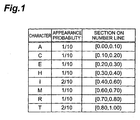
- arithmetic coding will be described with reference to Figs. 1 to 3. Specifically, a character string "ARITHMETIC" will be cited as the information source string to be coded, and the arithmetic coding thereof will be exemplified.
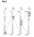
- Fig. 2 is a diagram illustrating the coding of the character string "ARITHMETIC" by use of the probability table shown in Fig. 1.
- a section reduction operation based on the probability table is sequentially carried out for the respective symbols included in the information source string, thus generating code words formed by coding the information source string.
- the probability table shown in Fig. 1 is referred to for the first character "A" of the character string "ARITHMETIC" to be coded, and the section [0, 1) on the number line is divided into eight sections corresponding to the respective characters. Then, the section is reduced to the section [0.0, 0.1) corresponding to the character "A” among the eight sections.
- the probability table is referred to for the second character "R", and the section [0.0, 0.1) is divided into eight sections. Subsequently, among these sections, the section is reduced to the section [0.07, 0.08) corresponding to the character "R".
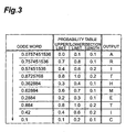
- Fig. 3 is a table showing decoding of the code word "0.0757451536" obtained by use of the probability table shown in Fig. 1 to the character string "ARITHMETIC".
- the probability table shown in Fig. 1 is referred to for the code word "0.0757451536" to be decoded, and the section [0.0, 0.1) having a section length of 0.1 in which the code word is included is specified. Then, the character “A” corresponding to the specified section is outputted as the first character, and a new code word "0.757451536" is generated by (code word - lower limit)/(section length). Next, the probability table is referred to for the code word "0.757451536", and a section [0.7, 0.8) having a section length of 0.1 in which the code word is included is specified. Then, the character “R” corresponding to the specified section is outputted as the second character, and a new code word "0.57451536" is generated.
- the symbols included in the information source string and the sections on the number line are allowed to correspond to each other, thus making it possible to express an arbitrary information source string by the code words on the number line of [0.0, 1.0).
- the probability table allowing the symbols and the sections to correspond to each other is set in accordance with the appearance probabilities of the respective symbols, whereby the variable-length coding of the information source string can be performed effectively and the efficiency of data compression by the coding can be enhanced.
- Fig. 4 is a flowchart illustrating an example of an image coding method using the variable-length coding by the foregoing arithmetic coding.
- arithmetic coding of image data is carried out by a method called CABAC (Context-based Adaptive Binary Arithmetic Coding) using context modeling which is used in ITU-T H.26L video coding system (refer to VCEG-M10 H.26L Test Model Long Term Number 8 (TML-8) draft0).
- CABAC Context-based Adaptive Binary Arithmetic Coding
- an image to be coded is first divided into blocks having a predetermined size, and intra-frame coding, inter-frame coding, and necessary data transform processing such as an orthogonal transform including the DCT are carried out for each of the blocks. Then, image data expressing an image in each block is generated. Subsequently, the variable-length coding is carried out for the image data by use of the arithmetic coding or the like, and coded data subjected to data compression is generated.
- the coding is not carried out under conditions that are set fixedly in advance, but the context modeling is carried out when the image data for each block is coded (Step S901, Context Modeling).
- Step S901 Context Modeling
- a probability table to be applied to the image data in the block to be coded is set so as to be switched with reference to coding conditions such as processing results of image coding in blocks adjacent thereto.
- the image data to be coded (for example, a plurality of DCT coefficients) is binarized, and a data string to be transmitted is generated (S902, Binarization). Then, the arithmetic coding is carried out for the binarized data string (S903, Adaptive Binary Arithmetic Coding), and the coded data is obtained.
- the probability table set by the context modeling is allocated to each bit of the binarized data string, and probability estimation is carried out (S904, Probability Estimation). Then, the data string undergoes the arithmetic coding by use of the allocated probability tables, and the code words on the number line, which are the coded data, are generated (S905, Arithmetic Coding). Moreover, information such as occurrence frequencies of the coded bits is feedbacked to the probability table based on processing results of the arithmetic coding, and thus the probability estimation is updated, and the coding trend is reflected on the probability table (S906, Probability Estimation Update).
- the probability table to be used is switched in accordance with the coding conditions and the processing results, thus making it possible to decrease the redundancy in the coded data.
- coded data obtained by coding a frame image is prepared by dividing a frame layer corresponding to the frame image into one or a plurality of slice layers.
- the slice layer is used for enhancing an efficiency of the data multiplexing and data transmission, or for suppressing an influence of a transmission error occurrence.
- a probability table applied to the arithmetic coding is initialized.
- the above initialization of the probability table has an effect enabling to resume decoding after the occurrence of the error.
- Fig. 4 when the arithmetic coding is performed in such a manner that a coding tendency is reflected on the probability table, there is a problem that information reflected on the probability table is lost by the initialization of the probability table at the slice layer.
- the probability table used in the initialization a fixed probability table is normally used regardless of an image of a coded object. Therefore, when the initialization is performed in accordance with a probability table unsuitable for the image, a coding efficiency is lowered at each initialization. Moreover, for the coded bit with low occurrence frequency, the probability table undergoes the initialization before the coding tendency is reflected on the probability table, and the coding efficiency is thereby lowered.
- the initialization is performed for recovering after the occurrence of the transmission error as above, however, the transmission error may not occur in the transmission path.
- the initialization of the probability table is inefficient.
- the probability table is unnecessarily initialized at the slice layer, data compression efficiency by coded data is thereby lowered.
- An object of the present invention is to provide image coding method, image decoding method, image coding apparatus, image decoding apparatus, program, computer data signal, and image transmission system, which are capable of enhancing the efficiency of the data compression by the coded data in a manner that the probability table is suitably set over the entire coded data having a hierarchy structure composed of a slice layer and a frame layer.
- the image coding method is a coding method for dividing a frame image into blocks of a specific size and coding image data for each of the blocks, the method comprising: (1) a transform step of preparing image data that is a coded object by performing a predetermined data transform operation for respective images of the blocks in the frame image; and (2) a coding step of subjecting the image data to variable-length coding by arithmetic coding using a predetermined probability table and of generating coded data having a hierarchy structure composed of a slice layer made of a plurality of the blocks, and a frame layer which is made of one or a plurality of the slice layers and corresponds to the frame image, (3) wherein, in the coding step, the presence of initialization of the probability table is set for the slice layer, a flag indicating the set presence of the initialization is added to a header of a predetermined layer of the coded data including the slice layer, and the probability table is initialized when the initialization is set to be
- the image coding apparatus is a coding apparatus for dividing a frame image into blocks of a specific size and coding image data for each of the blocks, the apparatus comprising: (1) transform means for preparing image data that is a coded object by performing a predetermined data transform operation for respective images of the blocks in the frame image; and (2) coding means for subjecting the image data to variable-length coding by arithmetic coding using a predetermined probability table and for generating coded data having a hierarchy structure composed of a slice layer made of a plurality of the blocks, and a frame layer which is made of one or a plurality of the slice layers and corresponds to the frame image, (3) wherein, by the coding means, the presence of initialization of the probability table is set for the slice layer, a flag indicating the set presence of the initialization is added to a header of a predetermined layer of the coded data including the slice layer, and the probability table is initialized when the initialization is set to be present.
- the image coding program according to the present invention is a program for causing a computer to execute the above-mentioned image coding method.
- the computer data signal according to the present invention is a data signal embodied in carrier wave for carrying an image coding program for causing a computer to execute the above-mentioned image coding method.
- the obtained image data is subjected to the arithmetic coding by use of a predetermined probability table, thereby generating coded data subjected to data compression.
- the variable-length coding for generating the coded data it is set for the slice layer, whether or not the probability table is initialized at the slice layer.
- a flag indicating presence of the initialization is added to the header of a specific layer.
- the probability table is suitably set over the entire coded data having the hierarchy structure composed of slice layers and frame layers, and the data compression efficiency by the coded data can be enhanced.
- the image decoding method is a decoding method for dividing a frame image into blocks of a specific size and decoding coded data obtained by coding image data for each of the blocks, the method comprising: (1) a decoding step of generating image data by subjecting the coded data to variable-length decoding by inverse arithmetic coding using a predetermined probability table, the coded data having a hierarchy structure composed of a slice layer made of a plurality of the blocks, and a frame layer which is made of one or a plurality of the slice layers and corresponds to the frame image; and (2) a restoration step of restoring the frame image by performing a predetermined data restoration operation for the image data of the respective blocks in the frame image, (3) wherein, in the decoding step, from a header of a predetermined layer in the coded data including the slice layer, a flag indicating the presence of initialization of the probability table with respect to the slice layer is read, the presence of the initialization of the probability table is set, and the probability table is
- the image decoding apparatus is a decoding apparatus for dividing a frame image into blocks of a specific size and decoding coded data obtained by coding image data for each of the blocks, the apparatus comprising: (1) decoding means for generating image data by subjecting the coded data to variable-length decoding by inverse arithmetic coding using a predetermined probability table, the coded data having a hierarchy structure composed of a slice layer made of a plurality of the blocks, and a frame layer which is made of one or a plurality of the slice layers and corresponds to the frame image; and (2) restoration means for restoring the frame image by performing a predetermined data restoration operation for the image data of the respective blocks in the frame image, (3) wherein, by the decoding means, from a header of a predetermined layer in the coded data including the slice layer, a flag indicating the presence of initialization of the probability table with respect to the slice layer is read, the presence of the initialization of the probability table is set, and the probability table is initialized when the
- the image decoding program according to the present invention is a program for causing a computer to execute the above-mentioned image decoding method.
- the computer data signal according to the present invention is a data signal embodied in carrier wave for carrying an image decoding program for causing a computer to execute the above-mentioned image decoding method.
- the image transmission system is an image transmission system for dividing a frame image into blocks of a specific size and transmitting the frame image in accordance with coded data obtained by coding image data for each of the blocks, the system comprising: (1) the above-mentioned image coding apparatus, which generates the coded data from the frame image and outputs the coded data; and (2) the above-mentioned image decoding apparatus, which receives the coded data from the image coding apparatus and restores the frame image.
- the image can be transmitted efficiently by use of the coded data with the enhanced efficiency of the data compression, which has the probability table suitably set over the entire coded data.
- Fig. 5 is a flowchart schematically showing one embodiment of the image coding method according to the present invention.
- This coding method is an image coding method, in which predetermined data transform and coding operations are carried out for an input frame image D1 as a frame image in a static image or a moving picture, and coded data D7 subjected to data compression is generated, the coded data D7 being transmittable in the image transmission system such as a mobile video transmission system.
- the input frame image D1 is first divided into blocks, each of which has a predetermined size (a predetermined number of pixels), and predetermined data transform operations are performed for respective images of the blocks in the frame image D1, thus preparing image data D6 that is a coded object (Step S100, a transform step).
- this transform step is composed of two steps, which are S101 and S102.
- image data is transformed by performing the predetermined data processing operation for the frame image D1, thus obtaining image data (spatial image data) D5 represented by spatial coordinates (Step S101).
- image data spatial image data
- MC motion compensation
- intra-frame coding for the frame images
- the image data of the input frame image D1 itself becomes the spatial image data D5.
- a plurality of orthogonal transform coefficients D6 are generated, which are image data (frequency image data) represented by an spatial frequency (S102, an orthogonal transform step).
- This orthogonal transform is performed for each of the blocks obtained by dividing the frame image, and the respective orthogonal transform coefficients D6 are obtained for the respective blocks included in the input frame image D1.
- a quantization operation is further performed for the orthogonal transform coefficients according to the need, and thus orthogonal transform coefficients (quantization coefficients) to be the image data of the coded object are generated.
- variable-length coding is carried out for the plurality of orthogonal transform coefficients D6 by use of the arithmetic coding, and the coded data D7 as compressed data is generated (S103, coding step).
- a predetermined probability table is set as the probability table applied to the orthogonal transform coefficients D6 (S104).
- the orthogonal transform coefficients D6 undergo the arithmetic coding by use of the set probability table (S105), thus obtaining the coded data D7.
- coded data is generated so as to have a hierarchy structure composed of a slice layer and a frame layer.
- Each slice layer is composed of a plurality of blocks.
- each frame layer is composed of one or a plurality of the slice layers and corresponds to the frame image.
- the slice layer is used for enhancing an efficiency of the data multiplexing and data transmission, or for suppressing an influence of a transmission error occurrence. Further, in the slice layer, normally, the probability table applied to the arithmetic coding is simultaneously initialized. As opposed to the above, in the image coding method of the present invention, the presence of the initialization of the probability table is set for each slice layer, a flag indicating the set presence of the initialization is added to a header of a predetermined layer of the coded data D7 including the above slice layer, and the probability table is initialized when the initialization is set to be present.
- the image data D6 is subjected to the arithmetic coding by use of the predetermined probability table, thus generating the coded data D7 subjected to the data compression.
- variable-length coding for generating the coded data D7, for the respective slice layer, it is set whether or not the probability table is initialized at the slice layer, and the flag indicating the presence of the initialization is added to the header of the predetermined layer.
- the probability table is suitably set over the entire coded data D7 having the hierarchy structure composed of slice layers and frame layers, and the data compression efficiency by the coded data D7 can be enhanced. Note that a specific method for adding a flag and the like will be described later in detail.
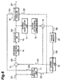
- Fig. 6 is a block diagram illustrating a constitution of one embodiment of the image coding apparatus according to the present invention. Description will be further made below for the image coding method shown in Fig. 5 with reference to the image coding apparatus shown in Fig. 6. Note that, in the following description, a moving picture composed of time-series frame images is mainly assumed as an object to be coded with regard to the input frame image D1 inputted to the image coding apparatus. However, the image coding method and apparatus according to the present invention can be applied similarly also to a static image composed of one frame.
- the input frame image D1 to be inputted as an object to be coded is first divided into square image blocks, each having a size of 16 pixels x 16 lines.
- Each of these image blocks is an image block serving as a unit for data processing such as motion compensation, and is called a macroblock.
- a DCT block having a size of 4 pixels x 4 lines is used in the DCT (orthogonal transform) to be described later, for example, in the H.26L coding scheme.
- one macroblock has sixteen luma blocks and eight chroma blocks in the DCT.
- the image coding is carried out for each of the blocks.
- the frame image D1 is inputted to transform means constituted by including a motion detection unit 11, a motion compensation unit 12, a subtracter 13, an orthogonal transform unit 14 and a quantization unit 15.
- the transform means performs a predetermined data transform operation for respective images of blocks in the frame image D1, and prepares the image data D6 to be the coded object.
- the frame image D1 is inputted to the motion detection unit 11, and the motion of the image is detected for each macroblock.
- the motion detection unit 11 compares image data in the macroblock, from which the motion is to be detected, with image data in other macroblocks in the input frame image or other frame images.
- the motion detection unit 11 detects the motion vector D2 indicating the motion of the image.
- the motion detection unit 11 refers to a specified image area in the locally decoded image D8 as a frame image having been coded, the image D8 being stored in the frame memory 20. Then, the motion detection unit 11 finds out a pattern analogous to the macroblock of the input frame image D1 to be coded currently. Subsequently, the motion detection unit 11 determines the motion vector D2 by a spatial movement amount between the analogous pattern and the macroblock. Moreover, in this event, a coding mode for use in the motion compensation in the macroblock is selected from a plurality of coding modes prepared for the motion compensation.
- Figs. 7A to 7J are schematic diagrams illustrating an example of coding modes prepared for the motion compensation.
- the coding modes exemplified in Figs. 7A to 7J there are prepared ten coding modes including: the skip mode 0 in which the motion compensation is not carried out; the inter modes 1 to 7 in which the inter-frame coding is carried out by use of block partitions to blocks for motion compensation, the block partitions being different from one another; and the intra modes 8 and 9 in which the intra-frame coding is carried out by use of block partitions different from each other.
- the foregoing motion vector D2 is imparted to each macroblock for each of the partitioned blocks for motion compensation.
- a motion prediction image is generated in the motion compensation unit 12 by use of the motion vector D2 from the motion detection unit 11 and the locally decoded image D8 from the frame memory 20.
- the motion vectors D2 are determined for the entire macroblocks included in the frame image D1 to generate the motion prediction image, thus obtaining the prediction frame image D4 for the input frame image D1.
- the difference (prediction residual) frame image D5 between the input frame image D1 and the prediction frame image D4 is generated.
- the input frame image D1 is used as the frame image D5 as it is.
- the image data of the difference frame image D5 is inputted to the orthogonal transform unit (orthogonal transform means) 14.
- the orthogonal transform is carried out to the difference frame image D5 by the spatial coordinates for each of the orthogonal transform blocks (for example, sixteen luma blocks and eight chroma blocks) included in the macroblock.
- orthogonal transform coefficients which are frequency image data, are generated.
- the orthogonal transform coefficients are quantized by a predetermined quantization parameter in the quantization unit 15, and thus the final orthogonal transform coefficient (quantization coefficient) D6 to be the image data subjected to the arithmetic coding is obtained.
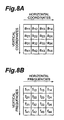
- Figs. 8A and 8B are diagrams illustrating an orthogonal transform of image data.
- the image data of each block divided for the purpose of the orthogonal transform in the frame image D5 is spatial image data.
- the image data is represented by 4x4 spatial image components a 11 to a 44 defined by the horizontal and vertical coordinates.
- the orthogonal transform unit 14 transforms the spatial image data into the image data shown in Fig. 8B by the orthogonal transform using a predetermined transform method.
- This image data is frequency image data, which is represented by the orthogonal transform coefficients f 11 to f 44 as 4 ⁇ 4 frequency image components defined by the horizontal and vertical frequencies.
- the DCT discrete cosine transform
- the DCT is an orthogonal transform using a term of cosine in the Fourier transform, and is often used in the image coding.
- the DCT is carried out for the spatial image data, and thus the DCT coefficients f 11 to f 44 as the frequency image data are generated.
- the 4x4 DCT blocks are used as blocks for the orthogonal transform in the DCT, for example, in the H.26L coding scheme.
- the orthogonal transform coefficients D6 generated by the orthogonal transform unit 14 and the quantization unit 15 undergo the variable-length coding by arithmetic coding using a predetermined probability table in the variable-length coding unit (coding means) 16.
- the coded data D7 as the compressed data of the input frame image D1 is generated.
- two-dimensional data of the orthogonal transform coefficients D6 shown in Fig. 8B is, for example, transformed into one-dimensional data by a zigzag scan and is further transformed into Level and Run data. Thereafter, the data thus obtained is binarized. Then, by subjecting a binary pattern obtained to the arithmetic coding, the coded data D7 is prepared.
- the motion vector D2 detected by the motion detection unit 11 and the coding mode information D3 showing the coding mode selected in the motion detection unit 11 are inputted to the variable-length coding unit 16.
- These motion vector D2 and coding mode information D3 undergo the variable-length coding by the arithmetic coding using a predetermined probability table in the variable-length coding unit 16 similarly to the orthogonal transform coefficients D6, and then are multiplexed on the coded data D7.
- the same processing as that described above regarding the image coding method shown in Fig. 5 is carried out.
- a probability table different from that used for the arithmetic coding of the orthogonal transform coefficients D6 is usually used in the arithmetic coding of the motion vector D2 and the coding mode information D3.
- different probability tables may be used for the arithmetic coding of the luma blocks and for the arithmetic coding of the chroma blocks.
- the orthogonal transform coefficients D6 generated in the orthogonal transform unit 14 and the quantization unit 15 are decoded by the inverse quantization unit 17 and the inverse orthogonal transform unit 18 in this image coding apparatus. Then, the decoded image data and the prediction frame image D4 are added together in the adder 19, and the locally decoded image D8 is generated. This locally decoded image D8 is stored in the frame memory 20, and is utilized for the motion compensation of other frame images.
- Fig. 9 is a flowchart schematically showing one embodiment of the image decoding method according to the present invention.
- This decoding method is an image decoding method, in which predetermined decoding and data restoration operations are carried out for the coded data D7 generated by the image coding method shown in Fig. 5, and an output frame image D10 is restored as an image corresponding to the input frame image D1.
- variable-length decoding is first carried out for the coded data D7 by use of inverse arithmetic coding, and a plurality of orthogonal transform coefficients (quantization coefficients) D6 as image data represented by spatial frequencies are generated (S201 decoding step).
- a predetermined probability table is set as a probability table to be applied to the coded data D7 (S202).
- the coded data D7 undergoes the inverse arithmetic coding by use of the set probability table (S203), thus obtaining the orthogonal transform coefficients D6 as frequency image data.
- the image decoding method of the embodiment with respect to each slice layer in the coded data D7 having the hierarchy structure composed of slice layers and frame layers, from a header of a predetermined layer of the coded data D7 including the above slice layer, a flag indicating the presence of the initialization of the probability table to the slice layer is read, and the presence of the initialization of the probability table at the slice layer is thus set. Simultaneously, the probability table is initialized when the initialization is set to be present.
- this restoration step is composed of two steps, which are S204 and S205.
- image data (spatial image data) D9 represented by the spatial coordinates is generated (S204, an inverse orthogonal transform step). Then, for the spatial image data D9, a predetermined data processing operation is performed to transform the image data, thus restoring the output frame image D10 (S205).
- the data restoration operation is performed for the image data D6, thus restoring the frame image D10. Then, in the variable-length decoding for decoding the coded data D7, it is set whether or not the probability table is initialized at the respective slice layer, by use of the flag which indicates the presence of the initialization and read from the header of the predetermined layer.
- Fig. 10 is a block diagram showing a constitution of one embodiment of the image decoding apparatus according to the present invention.
- the coded data D7 to be inputted as an object to be decoded is inputted to the variable-length decoding unit (decoding means) 21 and undergoes the variable-length decoding by the inverse arithmetic coding using a predetermined probability table, and thus the orthogonal transform coefficients D6 as the image data are generated.
- the variable-length decoding unit 21 detects the header of the frame layer, then decodes each piece of data included in the coded data D7 for each macroblock, and generates the orthogonal transform coefficients D6 as the frequency image data, the motion vector D2 and the like.
- the flag indicating the presence of the initialization of the probability table is read from the header of the predetermined layer, and the initialization of the probability table is performed if the initialization thereof is instructed.
- the orthogonal transform coefficients D6 decoded by the variable-length decoding unit 21 are inputted to restoration means constituted by including an inverse quantization unit 22, an inverse orthogonal transform unit 23, a motion compensation unit 24 and an adder 26.
- the restoration means performs the predetermined data restoration operation for the orthogonal transform coefficients D6, which are the image data of the respective blocks in the frame image, thereby restoring the frame image D10.
- the orthogonal transform coefficients D6 are subjected to the inverse quantization and inverse orthogonal transform by the inverse quantization unit 22 and inverse orthogonal transform unit (inverse orthogonal transform means) 23, respectively.
- a restoration difference frame image D9 that is the spatial image data is generated.
- This restoration difference frame image D9 is a frame image corresponding to the difference frame image D5 before the coding.
- the motion vector D2 is inputted to the motion compensation unit 24.
- the prediction frame image D4 is generated by use of the motion vector D2 from the variable-length decoding unit 21 and other frame images stored in the frame memory 25.
- the adder 26 the restored difference frame image D9 and the prediction frame image D4 are added together, and the restored frame image is outputted as the output frame image D10.
- processing activities of the image coding method executed in the above image coding apparatus are feasible by an image coding program for causing a computer to execute the image coding. Further, processing activities of the image decoding method executed in the above image decoding apparatus are feasible by an image decoding program for causing a computer to execute the image decoding.
- the image coding apparatus can be configured by using a CPU, a ROM connected to the CPU and storing respective software programs necessary for processing operations of the image coding, and a RAM connected to the CPU and temporarily storing data during execution of the program.
- the image coding apparatus is realized by executing the specific image coding program by the CPU.
- the image decoding apparatus can be configured by using a CPU, a ROM connected to the CPU and storing respective software programs necessary for processing operations of the image decoding, and a RAM connected to the CPU and temporarily storing data during execution of the program.
- the image decoding apparatus is realized by executing the specific image decoding program by the CPU.
- a record medium includes, for example: a magnetic medium such as a hard disc, a flexible disk and the like; an optical medium such as a CD-ROM, a DVD-ROM and the like; a magneto-optical medium such as a floptical disk and the like; a hardware device such as, for example, a RAM, a ROM, a semiconductor nonvolatile memory and the like, which is specially disposed so as to execute or store program instructions; and the like.
- the foregoing program for causing the computer to execute the image coding or image decoding can be made into a computer data signal embodied in carrier wave. Accordingly, the image coding program or image decoding program can be carried through the cable or wireless carrying path or the like.
- Figs. 11A and 11B are views showing an example of a data structure of coded data.
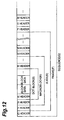
- Fig. 12 is a view showing an example of a data sequence of the coded data.
- Fig. 11A is a view showing an example of a hierarchy structure of the coded data.
- the coded data has six layers including block layer (hereinafter referred to as B), macroblock layer (M), slice layer (S), frame layer (F) and sequence layer (Q) in the order from lower data.
- B block layer
- M macroblock layer
- S slice layer
- F frame layer
- Q sequence layer
- the block layer B is a layer corresponding to a block to be a unit of transform in performing the orthogonal transform of the spatial image data into the frequency image data.
- the above-described block layer corresponds to the DCT block.
- the macroblock layer M is a layer corresponding to a macroblock to be a unit of prediction in performing the motion compensation inter-frame prediction for the image data.
- this macroblock layer M is composed of a plurality of block layers B (for example, 24 DCT block layers including 16 luma DCT blocks and 8 chroma DCT blocks).
- attribute information of the macroblock layer and the like is included in a header of the macroblock layer M (the M header shown in Fig. 12).
- the slice layer S corresponds to each of image regions obtained by dividing one frame image into one or a plurality of regions.
- the layer putting together these divided slice layers S becomes the frame layer (picture layer) F corresponding to the frame image.
- the frame layer F is a layer corresponding to the frame image and becomes a basic unit of coding in the image coding.
- the layers including all the frame layers F are assumed to be the sequence layer Q.
- a GOP layer composed of a plurality of frame layers F may be provided as an intermediate layer between the frame layer F and the sequence layer Q.
- Fig. 11B is a view showing an example of dividing the frame image into a plurality of slices.
- the frame image is divided into one or a plurality of slices (for example, 8 slices in Fig. 11B).
- These slices S are, as shown in Fig. 12, composed of one or a plurality of macroblocks M, and are constituted as an aggregate of the macroblocks, which begins from an upper left of the image and goes on to a lower right thereof in the order of a raster scanning.
- 8 slices are different lengths from each other in Fig. 11B, however, these slices may be a same length.
- each of the slice layers S obtained by dividing the frame layer F is a layer to be a unit of synchronization recovery.
- a synchronization code is added to a slice header (S header) that is a header of the slice layer S.
- each slice layer S it is set whether or not the probability table used for the arithmetic coding is initialized in the synchronization recovery by the synchronization code of the slice header. Then, a flag indicating the set presence of the initialization is added to a header of a predetermined layer including the slice layer S. Accordingly, unnecessary initialization of the probability table at the slice layer is prevented.
- the flag indicating the presence of the initialization of the probability table to each slice layer S a data structure is possible, in which, for example, the flag is added to the slice header (S header) of the slice layer itself subjected to the setting of the presence of the initialization.
- the presence of the initialization of the probability table at the slice layer can be set.
- a data structure is possible, in which the flag is added to a frame header (F header) of a frame layer including the slice layer subjected to the setting of the presence of the initialization.
- F header a frame header of a frame layer including the slice layer subjected to the setting of the presence of the initialization.
- the presence of the initialization of the probability table at the slice layer can be set with respect to the respective slice layers included in the frame layer.
- a data structure may also be used, in which the flag is added to a sequence header (Q header) of a sequence layer that is a layer including the whole layers.
- Q header a sequence header of a sequence layer that is a layer including the whole layers.
- the synchronization code is not added to the slice layer.
- the flag indicating the set presence of the initialization can be added to a header part of the packet.
- the instruction of the presence of the initialization may be made independently to the plurality of probability tables.
- the instruction thereof may also be made to the whole of the plurality of probability tables.
- the instruction of the presence of the initialization of the probability table may similarly be made, as to the probability table applied to the motion vector and the coding mode information.
- the presence of the initialization may be previously set to syntax or the probability table.
- the setting can be made also by switching the presence and absence of the initialization according to the need.
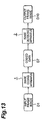
- Fig. 13 is a schematic diagram showing a constitution of one embodiment of an image transmission system (for example, a mobile video transmission system) according to the present invention.
- This image transmission system is constituted by including: the image coding apparatus (for example, the image coding apparatus shown in Fig. 6) 1 that realizes the image coding method shown in Fig. 5; and the image decoding apparatus (for example, the image decoding apparatus shown in Fig. 10) 2 that realizes the image decoding method shown in Fig. 9.
- the input frame image D1 is coded in the image coding apparatus 1, the coded data D7 is generated, and the coded data D7 is outputted to a predetermined wired or radio transmission path. Then, the coded data D7 transmitted from the image coding apparatus 1 through the transmission path is inputted to the image decoding apparatus 2, and is restored as an output frame image D10.
- the image can be transmitted efficiently by use of the coded data with the enhanced efficiency of the data compression, which has the probability table suitably set over the entire coded data.
- the image coding method, image decoding method, image coding apparatus, image decoding apparatus, program, computer data signal, and image transmission system of the present invention are applicable as a method and apparatus and the like which are capable of enhancing the efficiency of the data compression by the coded data in a manner that the probability table is suitably set over the entire coded data having a hierarchy structure composed of slice layers and frame layers.
- the probability table is suitably set over the entire coded data having the hierarchy structure composed of slice layers and frame layers, and thus the efficiency of the data compression by the coded data can be enhanced.
Landscapes
- Engineering & Computer Science (AREA)
- Multimedia (AREA)
- Signal Processing (AREA)
- Computing Systems (AREA)
- Theoretical Computer Science (AREA)
- Compression Or Coding Systems Of Tv Signals (AREA)
- Compression, Expansion, Code Conversion, And Decoders (AREA)
- Image Processing (AREA)
- Compression Of Band Width Or Redundancy In Fax (AREA)
Abstract
Orthogonal transform coefficients D6, which are
image data of a coded object, are generated by
performing predetermined data transform operations on
frame image D1 (Step S100), and coded data D7 is
generated (S103) by subjecting the orthogonal
transform coefficients D6 to arithmetic coding using a
predetermined probability table. Then, in variable-length
coding for generating the coded data D7, it is
set whether or not a probability table is initialized
at the slice layer, and a flag indicating the presence
of the initialization is added to a header of a
predetermined layer. Thus, the image coding method,
image decoding method, image coding apparatus, image
decoding apparatus, program, computer data signal, and
image transmission system, which are capable of
enhancing data compression efficiency by coded data in
a manner that a probability table is suitably set over
the entire coded data, are realized.
Description
The present invention relates to an image coding
method, an image decoding method, an image coding
apparatus, an image decoding apparatus, a program, and
a computer data signal which can be suitably applied
to an image transmission system such as a mobile video
transmission system, and relates to the image
transmission system.
As a coding method for a moving picture,
standard moving picture coding methods such as ITU-T
H.26x and MPEG series have been heretofore known. In
these moving picture coding methods, predetermined
data transform operations such as motion compensation
(MC) and discrete cosine transform (hereinafter
referred to as DCT) are performed for respective
images of blocks obtained by dividing a frame image.
Thus, image data that is a coded object is prepared.
The image data prepared by the data transform
operations further undergoes variable-length coding,
and becomes coded data that is compressed data used
for an image transfer. As one of such variable-length
coding methods, an arithmetic coding (AC) has been
used.
In general, in the case of carrying out the
arithmetic coding of an information source string
(symbol string) formed by combining plural types of
symbols, first, certain sections are allocated to the
respective symbols in accordance with the appearance
probabilities of the symbols on a number line
(probability number line) of [0.0, 1.0). In this case,
one representing correspondence relationships between
the symbols and the sections on the number line is
called a probability table. When the information
source string undergoes the variable-length coding by
the arithmetic coding, code words expressing the
information source string on the number line is
generated by referring to this probability table.
Here, the arithmetic coding will be described
with reference to Figs. 1 to 3. Specifically, a
character string "ARITHMETIC" will be cited as the
information source string to be coded, and the
arithmetic coding thereof will be exemplified.
Eight types of characters (symbols), which are A,
C, E, H, I, M, R and T, appear in the above-described
information source string. As shown in the table of
Fig. 1, sections are allocated to these characters on
the number line (probability number line) of [0.0,
1.0) such that section lengths proportional to the
appearance probabilities of the respective characters
in the character string can be obtained. The table
shown in Fig. 1, which represents these correspondence
relationships between the characters and the sections
on the number line, becomes a probability table for
use in the arithmetic coding.
Fig. 2 is a diagram illustrating the coding of
the character string "ARITHMETIC" by use of the
probability table shown in Fig. 1. In the arithmetic
coding, a section reduction operation based on the
probability table is sequentially carried out for the
respective symbols included in the information source
string, thus generating code words formed by coding
the information source string.
In the example shown in Fig. 2, first, the
probability table shown in Fig. 1 is referred to for
the first character "A" of the character string
"ARITHMETIC" to be coded, and the section [0, 1) on
the number line is divided into eight sections
corresponding to the respective characters. Then, the
section is reduced to the section [0.0, 0.1)
corresponding to the character "A" among the eight
sections. Next, the probability table is referred to
for the second character "R", and the section [0.0,
0.1) is divided into eight sections. Subsequently,
among these sections, the section is reduced to the
section [0.07, 0.08) corresponding to the character
"R".
Hereinafter, the coding operations by the section
reduction are carried out sequentially for each of the
characters. Then, in the section [0.0757451536,
0.0757451552) on the number line finally obtained, a
numerical value "0.0757451536" within the section is
generated as a code word obtained by performing the
arithmetic coding of the character string "ARITHMETIC".
Fig. 3 is a table showing decoding of the code
word "0.0757451536" obtained by use of the probability
table shown in Fig. 1 to the character string
"ARITHMETIC".
In the example shown in Fig. 3, the probability
table shown in Fig. 1 is referred to for the code word
"0.0757451536" to be decoded, and the section [0.0,
0.1) having a section length of 0.1 in which the code
word is included is specified. Then, the character
"A" corresponding to the specified section is
outputted as the first character, and a new code word
"0.757451536" is generated by (code word - lower
limit)/(section length). Next, the probability table
is referred to for the code word "0.757451536", and a
section [0.7, 0.8) having a section length of 0.1 in
which the code word is included is specified. Then,
the character "R" corresponding to the specified
section is outputted as the second character, and a
new code word "0.57451536" is generated.
Hereinafter, the decoding operations are
sequentially carried out for the code words. Then,
the character string "ARITHMETIC" is restored from the
code word "0.0757451536" which underwent the
arithmetic coding.
As described above, in the variable-length coding
of the information source string by use of the
arithmetic coding, the symbols included in the
information source string and the sections on the
number line are allowed to correspond to each other,
thus making it possible to express an arbitrary
information source string by the code words on the
number line of [0.0, 1.0). Moreover, the probability
table allowing the symbols and the sections to
correspond to each other is set in accordance with the
appearance probabilities of the respective symbols,
whereby the variable-length coding of the information
source string can be performed effectively and the
efficiency of data compression by the coding can be
enhanced.
Fig. 4 is a flowchart illustrating an example of
an image coding method using the variable-length
coding by the foregoing arithmetic coding. In the
image coding method shown in Fig. 4, arithmetic coding
of image data is carried out by a method called CABAC
(Context-based Adaptive Binary Arithmetic Coding)
using context modeling which is used in ITU-T H.26L
video coding system (refer to VCEG-M10 H.26L Test
Model Long Term Number 8 (TML-8) draft0).
In the coding of the image data, an image to be
coded is first divided into blocks having a
predetermined size, and intra-frame coding, inter-frame
coding, and necessary data transform processing
such as an orthogonal transform including the DCT are
carried out for each of the blocks. Then, image data
expressing an image in each block is generated.
Subsequently, the variable-length coding is carried
out for the image data by use of the arithmetic coding
or the like, and coded data subjected to data
compression is generated.
Particularly, in the image coding method shown in
Fig. 4, the coding is not carried out under conditions
that are set fixedly in advance, but the context
modeling is carried out when the image data for each
block is coded (Step S901, Context Modeling). In the
arithmetic coding using the context modeling, with
regard to the probability table for use in the coding
of the image data, a probability table to be applied
to the image data in the block to be coded is set so
as to be switched with reference to coding conditions
such as processing results of image coding in blocks
adjacent thereto.
When the setting of the probability table by the
context modeling is terminated, the image data to be
coded (for example, a plurality of DCT coefficients)
is binarized, and a data string to be transmitted is
generated (S902, Binarization). Then, the arithmetic
coding is carried out for the binarized data string
(S903, Adaptive Binary Arithmetic Coding), and the
coded data is obtained.
Specifically, the probability table set by the
context modeling is allocated to each bit of the
binarized data string, and probability estimation is
carried out (S904, Probability Estimation). Then, the
data string undergoes the arithmetic coding by use of
the allocated probability tables, and the code words
on the number line, which are the coded data, are
generated (S905, Arithmetic Coding). Moreover,
information such as occurrence frequencies of the
coded bits is feedbacked to the probability table
based on processing results of the arithmetic coding,
and thus the probability estimation is updated, and
the coding trend is reflected on the probability table
(S906, Probability Estimation Update).
According to the foregoing image coding method by
the arithmetic coding using the context modeling, the
probability table to be used is switched in accordance
with the coding conditions and the processing results,
thus making it possible to decrease the redundancy in
the coded data.
In some cases, coded data obtained by coding a
frame image is prepared by dividing a frame layer
corresponding to the frame image into one or a
plurality of slice layers. The slice layer is used
for enhancing an efficiency of the data multiplexing
and data transmission, or for suppressing an influence
of a transmission error occurrence.
Meanwhile, at the slice layer, a probability
table applied to the arithmetic coding is initialized.
The above initialization of the probability table has
an effect enabling to resume decoding after the
occurrence of the error. However, as shown in Fig. 4,
when the arithmetic coding is performed in such a
manner that a coding tendency is reflected on the
probability table, there is a problem that information
reflected on the probability table is lost by the
initialization of the probability table at the slice
layer.
Namely, for the probability table used in the
initialization, a fixed probability table is normally
used regardless of an image of a coded object.
Therefore, when the initialization is performed in
accordance with a probability table unsuitable for the
image, a coding efficiency is lowered at each
initialization. Moreover, for the coded bit with low
occurrence frequency, the probability table undergoes
the initialization before the coding tendency is
reflected on the probability table, and the coding
efficiency is thereby lowered.
Moreover, the initialization is performed for
recovering after the occurrence of the transmission
error as above, however, the transmission error may
not occur in the transmission path. In the case that
the transmission error does not occur, or in the case
that the transmission error occurrence frequency is
low, the initialization of the probability table is
inefficient. Thus, in the case that the probability
table is unnecessarily initialized at the slice layer,
data compression efficiency by coded data is thereby
lowered.
The present invention is made for solving the
above problems. An object of the present invention is
to provide image coding method, image decoding method,
image coding apparatus, image decoding apparatus,
program, computer data signal, and image transmission
system, which are capable of enhancing the efficiency
of the data compression by the coded data in a manner
that the probability table is suitably set over the
entire coded data having a hierarchy structure
composed of a slice layer and a frame layer.
In order to achieve the above object, the image
coding method according to the present invention is a
coding method for dividing a frame image into blocks
of a specific size and coding image data for each of
the blocks, the method comprising: (1) a transform
step of preparing image data that is a coded object by
performing a predetermined data transform operation
for respective images of the blocks in the frame
image; and (2) a coding step of subjecting the image
data to variable-length coding by arithmetic coding
using a predetermined probability table and of
generating coded data having a hierarchy structure
composed of a slice layer made of a plurality of the
blocks, and a frame layer which is made of one or a
plurality of the slice layers and corresponds to the
frame image, (3) wherein, in the coding step, the
presence of initialization of the probability table is
set for the slice layer, a flag indicating the set
presence of the initialization is added to a header of
a predetermined layer of the coded data including the
slice layer, and the probability table is initialized
when the initialization is set to be present.
Similarly, the image coding apparatus according
to the present invention is a coding apparatus for
dividing a frame image into blocks of a specific size
and coding image data for each of the blocks, the
apparatus comprising: (1) transform means for
preparing image data that is a coded object by
performing a predetermined data transform operation
for respective images of the blocks in the frame
image; and (2) coding means for subjecting the image
data to variable-length coding by arithmetic coding
using a predetermined probability table and for
generating coded data having a hierarchy structure
composed of a slice layer made of a plurality of the
blocks, and a frame layer which is made of one or a
plurality of the slice layers and corresponds to the
frame image, (3) wherein, by the coding means, the
presence of initialization of the probability table is
set for the slice layer, a flag indicating the set
presence of the initialization is added to a header of
a predetermined layer of the coded data including the
slice layer, and the probability table is initialized
when the initialization is set to be present.
Similarly, the image coding program according to
the present invention is a program for causing a
computer to execute the above-mentioned image coding
method. Further, the computer data signal according
to the present invention is a data signal embodied in
carrier wave for carrying an image coding program for
causing a computer to execute the above-mentioned
image coding method.
In the foregoing image coding method, apparatus,
program, and computer data signal, after obtaining
image data of a coded object by performing a data
transform operation, such as the motion compensation
and orthogonal transform, for a frame image, the
obtained image data is subjected to the arithmetic
coding by use of a predetermined probability table,
thereby generating coded data subjected to data
compression. Then, according to the variable-length
coding for generating the coded data, it is set for
the slice layer, whether or not the probability table
is initialized at the slice layer. At the same time,
to the header of a specific layer, a flag indicating
presence of the initialization is added.
Accordingly, unnecessary initialization of the
probability table at the slice layer can be prevented.
Therefore, the probability table is suitably set over
the entire coded data having the hierarchy structure
composed of slice layers and frame layers, and the
data compression efficiency by the coded data can be
enhanced.
Moreover, the image decoding method according to
the present invention is a decoding method for
dividing a frame image into blocks of a specific size
and decoding coded data obtained by coding image data
for each of the blocks, the method comprising: (1) a
decoding step of generating image data by subjecting
the coded data to variable-length decoding by inverse
arithmetic coding using a predetermined probability
table, the coded data having a hierarchy structure
composed of a slice layer made of a plurality of the
blocks, and a frame layer which is made of one or a
plurality of the slice layers and corresponds to the
frame image; and (2) a restoration step of restoring
the frame image by performing a predetermined data
restoration operation for the image data of the
respective blocks in the frame image, (3) wherein, in
the decoding step, from a header of a predetermined
layer in the coded data including the slice layer, a
flag indicating the presence of initialization of the
probability table with respect to the slice layer is
read, the presence of the initialization of the
probability table is set, and the probability table is
initialized when the initialization is set to be
present.
Similarly, the image decoding apparatus according
to the present invention is a decoding apparatus for
dividing a frame image into blocks of a specific size
and decoding coded data obtained by coding image data
for each of the blocks, the apparatus comprising: (1)
decoding means for generating image data by subjecting
the coded data to variable-length decoding by inverse
arithmetic coding using a predetermined probability
table, the coded data having a hierarchy structure
composed of a slice layer made of a plurality of the
blocks, and a frame layer which is made of one or a
plurality of the slice layers and corresponds to the
frame image; and (2) restoration means for restoring
the frame image by performing a predetermined data
restoration operation for the image data of the
respective blocks in the frame image, (3) wherein, by
the decoding means, from a header of a predetermined
layer in the coded data including the slice layer, a
flag indicating the presence of initialization of the
probability table with respect to the slice layer is
read, the presence of the initialization of the
probability table is set, and the probability table is
initialized when the initialization is set to be
present.
Similarly, the image decoding program according
to the present invention is a program for causing a
computer to execute the above-mentioned image decoding
method. Further, the computer data signal according to
the present invention is a data signal embodied in
carrier wave for carrying an image decoding program
for causing a computer to execute the above-mentioned
image decoding method.
In the foregoing image decoding method, apparatus,
program, and computer data signal, after obtaining
image data by performing inverse arithmetic coding for
coded data by use of a predetermined probability table,
a data restoration operation is performed for the
obtained image data, thereby restoring a frame image.
Then, according to variable-length decoding for
decoding the coded data, for the slice layer, it is
set whether or not the probability table is
initialized at the slice layer, by use of the flag
indicating presence of the initialization, which is
read from the header of a specific layer.
Similarly to the foregoing case of the arithmetic
coding, unnecessary initialization of the probability
table at the slice layer can be accordingly prevented.
Therefore, from the coded data with the enhanced
efficiency of the data compression, which is obtained
by suitably setting the probability table over the
entire coded data having the hierarchy structure
composed of slice layers and frame layers, the frame
image can be suitably restored.
Moreover, the image transmission system according
to the present invention is an image transmission
system for dividing a frame image into blocks of a
specific size and transmitting the frame image in
accordance with coded data obtained by coding image
data for each of the blocks, the system comprising:
(1) the above-mentioned image coding apparatus, which
generates the coded data from the frame image and
outputs the coded data; and (2) the above-mentioned
image decoding apparatus, which receives the coded
data from the image coding apparatus and restores the
frame image.
With such image transmission system, the image
can be transmitted efficiently by use of the coded
data with the enhanced efficiency of the data
compression, which has the probability table suitably
set over the entire coded data.
Description will be made below in detail with
reference to the drawings for preferred embodiments of
an image coding method, an image decoding method, an
image coding apparatus, an image decoding apparatus, a
program, a computer data signal, and an image
transmission system using these methods and
apparatuses, all of which are according to the present
invention. Note that, in descriptions of the drawings,
the same reference numerals will be added to the same
elements, and repeated explanations will be omitted.
Moreover, dimension ratios of the drawings do not
always coincide with those in the descriptions thereof.
First, the image coding method and the image
coding apparatus will be described.
Fig. 5 is a flowchart schematically showing one
embodiment of the image coding method according to the
present invention. This coding method is an image
coding method, in which predetermined data transform
and coding operations are carried out for an input
frame image D1 as a frame image in a static image or a
moving picture, and coded data D7 subjected to data
compression is generated, the coded data D7 being
transmittable in the image transmission system such as
a mobile video transmission system.
In the image coding method shown in Fig. 5, the
input frame image D1 is first divided into blocks,
each of which has a predetermined size (a
predetermined number of pixels), and predetermined
data transform operations are performed for respective
images of the blocks in the frame image D1, thus
preparing image data D6 that is a coded object (Step
S100, a transform step). In the embodiment, this
transform step is composed of two steps, which are
S101 and S102.
Specifically, image data is transformed by
performing the predetermined data processing operation
for the frame image D1, thus obtaining image data
(spatial image data) D5 represented by spatial
coordinates (Step S101). For the data processing
operations performed herein, there is, for example,
motion compensation (MC) inter-frame prediction in the
case of performing inter-frame coding for frame images
of a moving picture. Moreover, in the case of
performing intra-frame coding for the frame images,
for example, the image data of the input frame image
D1 itself becomes the spatial image data D5.
Next, by performing a orthogonal transform
operation for the spatial image data D5, a plurality
of orthogonal transform coefficients D6 are generated,
which are image data (frequency image data)
represented by an spatial frequency (S102, an
orthogonal transform step). This orthogonal transform
is performed for each of the blocks obtained by
dividing the frame image, and the respective
orthogonal transform coefficients D6 are obtained for
the respective blocks included in the input frame
image D1. Moreover, a quantization operation is
further performed for the orthogonal transform
coefficients according to the need, and thus
orthogonal transform coefficients (quantization
coefficients) to be the image data of the coded object
are generated.
Subsequently, variable-length coding is carried
out for the plurality of orthogonal transform
coefficients D6 by use of the arithmetic coding, and
the coded data D7 as compressed data is generated
(S103, coding step). Specifically, a predetermined
probability table is set as the probability table
applied to the orthogonal transform coefficients D6
(S104). Then, the orthogonal transform coefficients
D6 undergo the arithmetic coding by use of the set
probability table (S105), thus obtaining the coded
data D7.
In the image coding method of the embodiment, for
the coded data D7 obtained by subjecting the
orthogonal transform coefficients D6, which are the
image data of the coded object, to the arithmetic
coding, coded data is generated so as to have a
hierarchy structure composed of a slice layer and a
frame layer. Each slice layer is composed of a
plurality of blocks. Moreover, each frame layer is
composed of one or a plurality of the slice layers and
corresponds to the frame image.
The slice layer is used for enhancing an
efficiency of the data multiplexing and data
transmission, or for suppressing an influence of a
transmission error occurrence. Further, in the slice
layer, normally, the probability table applied to the
arithmetic coding is simultaneously initialized. As
opposed to the above, in the image coding method of
the present invention, the presence of the
initialization of the probability table is set for
each slice layer, a flag indicating the set presence
of the initialization is added to a header of a
predetermined layer of the coded data D7 including the
above slice layer, and the probability table is
initialized when the initialization is set to be
present.
The effect of the image coding method according
to this embodiment will be described.
In the image coding method shown in Fig. 5, after
obtaining the image data D6 of the coded object by
performing the data transform operations, such as the
motion compensation and the orthogonal transform, for
the frame image D1, the image data D6 is subjected to
the arithmetic coding by use of the predetermined
probability table, thus generating the coded data D7
subjected to the data compression. Then, according to
variable-length coding for generating the coded data
D7, for the respective slice layer, it is set whether
or not the probability table is initialized at the
slice layer, and the flag indicating the presence of
the initialization is added to the header of the
predetermined layer.
Accordingly, unnecessary initialization of the
probability table at the slice layer can be prevented.
Therefore, the probability table is suitably set over
the entire coded data D7 having the hierarchy
structure composed of slice layers and frame layers,
and the data compression efficiency by the coded data
D7 can be enhanced. Note that a specific method for
adding a flag and the like will be described later in
detail.
Fig. 6 is a block diagram illustrating a
constitution of one embodiment of the image coding
apparatus according to the present invention.
Description will be further made below for the image
coding method shown in Fig. 5 with reference to the
image coding apparatus shown in Fig. 6. Note that, in
the following description, a moving picture composed
of time-series frame images is mainly assumed as an
object to be coded with regard to the input frame
image D1 inputted to the image coding apparatus.
However, the image coding method and apparatus
according to the present invention can be applied
similarly also to a static image composed of one frame.
The input frame image D1 to be inputted as an
object to be coded is first divided into square image
blocks, each having a size of 16 pixels x 16 lines.
Each of these image blocks is an image block serving
as a unit for data processing such as motion
compensation, and is called a macroblock. Note that a
DCT block having a size of 4 pixels x 4 lines is used
in the DCT (orthogonal transform) to be described
later, for example, in the H.26L coding scheme. In
this case, one macroblock has sixteen luma blocks and
eight chroma blocks in the DCT. The image coding is
carried out for each of the blocks.
The frame image D1 is inputted to transform means
constituted by including a motion detection unit 11, a
motion compensation unit 12, a subtracter 13, an
orthogonal transform unit 14 and a quantization unit
15. The transform means performs a predetermined data
transform operation for respective images of blocks in
the frame image D1, and prepares the image data D6 to
be the coded object.
First, the frame image D1 is inputted to the
motion detection unit 11, and the motion of the image
is detected for each macroblock. The motion detection
unit 11 compares image data in the macroblock, from
which the motion is to be detected, with image data in
other macroblocks in the input frame image or other
frame images. Thus, the motion detection unit 11
detects the motion vector D2 indicating the motion of
the image.
Specifically, the motion detection unit 11 refers
to a specified image area in the locally decoded image
D8 as a frame image having been coded, the image D8
being stored in the frame memory 20. Then, the motion
detection unit 11 finds out a pattern analogous to the
macroblock of the input frame image D1 to be coded
currently. Subsequently, the motion detection unit 11
determines the motion vector D2 by a spatial movement
amount between the analogous pattern and the
macroblock. Moreover, in this event, a coding mode
for use in the motion compensation in the macroblock
is selected from a plurality of coding modes prepared
for the motion compensation.
Figs. 7A to 7J are schematic diagrams
illustrating an example of coding modes prepared for
the motion compensation. In the coding modes
exemplified in Figs. 7A to 7J, there are prepared ten
coding modes including: the skip mode 0 in which the
motion compensation is not carried out; the inter
modes 1 to 7 in which the inter-frame coding is
carried out by use of block partitions to blocks for
motion compensation, the block partitions being
different from one another; and the intra modes 8 and
9 in which the intra-frame coding is carried out by
use of block partitions different from each other.
Note that the foregoing motion vector D2 is imparted
to each macroblock for each of the partitioned blocks
for motion compensation.
After the motion vector D2 is obtained, a motion
prediction image is generated in the motion
compensation unit 12 by use of the motion vector D2
from the motion detection unit 11 and the locally
decoded image D8 from the frame memory 20. The motion
vectors D2 are determined for the entire macroblocks
included in the frame image D1 to generate the motion
prediction image, thus obtaining the prediction frame
image D4 for the input frame image D1. Subsequently,
in the subtractor 13, the difference (prediction
residual) frame image D5 between the input frame image
D1 and the prediction frame image D4 is generated.
Moreover, in the case where the prediction frame image
D4 is not prepared, the input frame image D1 is used
as the frame image D5 as it is.
The image data of the difference frame image D5
is inputted to the orthogonal transform unit
(orthogonal transform means) 14. In the orthogonal
transform unit 14, the orthogonal transform is carried
out to the difference frame image D5 by the spatial
coordinates for each of the orthogonal transform
blocks (for example, sixteen luma blocks and eight
chroma blocks) included in the macroblock. Then,
orthogonal transform coefficients, which are frequency
image data, are generated. Moreover, the orthogonal
transform coefficients are quantized by a
predetermined quantization parameter in the
quantization unit 15, and thus the final orthogonal
transform coefficient (quantization coefficient) D6 to
be the image data subjected to the arithmetic coding
is obtained.
Figs. 8A and 8B are diagrams illustrating an
orthogonal transform of image data. The image data of
each block divided for the purpose of the orthogonal
transform in the frame image D5 is spatial image data.
As exemplified by sixteen (4×4) image components in
Fig. 8A, the image data is represented by 4x4 spatial
image components a11 to a44 defined by the horizontal
and vertical coordinates. The orthogonal transform
unit 14 transforms the spatial image data into the
image data shown in Fig. 8B by the orthogonal
transform using a predetermined transform method.
This image data is frequency image data, which is
represented by the orthogonal transform coefficients
f11 to f44 as 4×4 frequency image components defined by
the horizontal and vertical frequencies.
As a specific orthogonal transform, for example,
the DCT (discrete cosine transform) can be applied.
The DCT is an orthogonal transform using a term of
cosine in the Fourier transform, and is often used in
the image coding. The DCT is carried out for the
spatial image data, and thus the DCT coefficients f11
to f44 as the frequency image data are generated. Note
that, as shown in Figs. 8A and 8B, the 4x4 DCT blocks
are used as blocks for the orthogonal transform in the
DCT, for example, in the H.26L coding scheme.
The orthogonal transform coefficients D6
generated by the orthogonal transform unit 14 and the
quantization unit 15 undergo the variable-length
coding by arithmetic coding using a predetermined
probability table in the variable-length coding unit
(coding means) 16. Thus, the coded data D7 as the
compressed data of the input frame image D1 is
generated.
Specifically, two-dimensional data of the
orthogonal transform coefficients D6 shown in Fig. 8B
is, for example, transformed into one-dimensional data
by a zigzag scan and is further transformed into Level
and Run data. Thereafter, the data thus obtained is
binarized. Then, by subjecting a binary pattern
obtained to the arithmetic coding, the coded data D7
is prepared.
Moreover, in addition to the orthogonal transform
coefficients D6, the motion vector D2 detected by the
motion detection unit 11 and the coding mode
information D3 showing the coding mode selected in the
motion detection unit 11 are inputted to the variable-length
coding unit 16. These motion vector D2 and
coding mode information D3 undergo the variable-length
coding by the arithmetic coding using a predetermined
probability table in the variable-length coding unit
16 similarly to the orthogonal transform coefficients
D6, and then are multiplexed on the coded data D7.
Here, regarding the setting and the
initialization of the probability table for use in the
arithmetic coding in the variable-length coding unit
16, the setting of the presence of the initialization
to the slice layer, and the addition of the flag to
the coded data, the same processing as that described
above regarding the image coding method shown in Fig.
5 is carried out. Moreover, a probability table
different from that used for the arithmetic coding of
the orthogonal transform coefficients D6 is usually
used in the arithmetic coding of the motion vector D2
and the coding mode information D3. Moreover, also in
the arithmetic coding of the orthogonal transform
coefficients D6, different probability tables may be
used for the arithmetic coding of the luma blocks and
for the arithmetic coding of the chroma blocks.
Furthermore, the orthogonal transform
coefficients D6 generated in the orthogonal transform
unit 14 and the quantization unit 15 are decoded by
the inverse quantization unit 17 and the inverse
orthogonal transform unit 18 in this image coding
apparatus. Then, the decoded image data and the
prediction frame image D4 are added together in the
adder 19, and the locally decoded image D8 is
generated. This locally decoded image D8 is stored in
the frame memory 20, and is utilized for the motion
compensation of other frame images.
Next, the image decoding method and the image
decoding apparatus will be described.
Fig. 9 is a flowchart schematically showing one
embodiment of the image decoding method according to
the present invention. This decoding method is an
image decoding method, in which predetermined decoding
and data restoration operations are carried out for
the coded data D7 generated by the image coding method
shown in Fig. 5, and an output frame image D10 is
restored as an image corresponding to the input frame
image D1.
In the image decoding method shown in Fig. 9,
variable-length decoding is first carried out for the
coded data D7 by use of inverse arithmetic coding, and
a plurality of orthogonal transform coefficients
(quantization coefficients) D6 as image data
represented by spatial frequencies are generated (S201
decoding step). Specifically, a predetermined
probability table is set as a probability table to be
applied to the coded data D7 (S202). Then, the coded
data D7 undergoes the inverse arithmetic coding by use
of the set probability table (S203), thus obtaining
the orthogonal transform coefficients D6 as frequency
image data.
In the image decoding method of the embodiment,
with respect to each slice layer in the coded data D7
having the hierarchy structure composed of slice
layers and frame layers, from a header of a
predetermined layer of the coded data D7 including the
above slice layer, a flag indicating the presence of
the initialization of the probability table to the
slice layer is read, and the presence of the
initialization of the probability table at the slice
layer is thus set. Simultaneously, the probability
table is initialized when the initialization is set to
be present.
Next, the predetermined data restoration
operation is performed for the orthogonal transform
coefficients D6, which are the image data of the
respective blocks in the frame image, thereby
restoring the frame image (S200, a restoration step).
In the embodiment, this restoration step is composed
of two steps, which are S204 and S205.
Specifically, by sequentially performing inverse
quantization operation and inverse orthogonal
transform operation for the orthogonal transform
coefficients D6, image data (spatial image data) D9
represented by the spatial coordinates is generated
(S204, an inverse orthogonal transform step). Then,
for the spatial image data D9, a predetermined data
processing operation is performed to transform the
image data, thus restoring the output frame image D10
(S205).
The effect of the image decoding method according
to this embodiment will be described.
In the image decoding method shown in Fig. 9,
after obtaining the image data D6 by performing the
inverse arithmetic coding of the coded data D7 by use
of the predetermined probability table, the data
restoration operation is performed for the image data
D6, thus restoring the frame image D10. Then, in the
variable-length decoding for decoding the coded data
D7, it is set whether or not the probability table is
initialized at the respective slice layer, by use of
the flag which indicates the presence of the
initialization and read from the header of the
predetermined layer.
Similarly to the foregoing case of the arithmetic
coding, unnecessary initialization of the.probability
table at the slice layer can be accordingly prevented.
Therefore, from the coded data D7 with the enhanced
efficiency of the data compression, which is obtained
by suitably setting the probability table over the
entire coded data D7 having the hierarchy structure
composed of slice layers and frame layers, the frame
image can be suitably restored.
Fig. 10 is a block diagram showing a constitution
of one embodiment of the image decoding apparatus
according to the present invention.
The coded data D7 to be inputted as an object to
be decoded is inputted to the variable-length decoding
unit (decoding means) 21 and undergoes the variable-length
decoding by the inverse arithmetic coding using
a predetermined probability table, and thus the
orthogonal transform coefficients D6 as the image data
are generated. For the coded data D7 subjected to the
data compression, the variable-length decoding unit 21
detects the header of the frame layer, then decodes
each piece of data included in the coded data D7 for
each macroblock, and generates the orthogonal
transform coefficients D6 as the frequency image data,
the motion vector D2 and the like. Moreover, as to
each slice layer included in the frame layer, the flag
indicating the presence of the initialization of the
probability table is read from the header of the
predetermined layer, and the initialization of the
probability table is performed if the initialization
thereof is instructed.
The orthogonal transform coefficients D6 decoded
by the variable-length decoding unit 21 are inputted
to restoration means constituted by including an
inverse quantization unit 22, an inverse orthogonal
transform unit 23, a motion compensation unit 24 and
an adder 26. The restoration means performs the
predetermined data restoration operation for the
orthogonal transform coefficients D6, which are the
image data of the respective blocks in the frame image,
thereby restoring the frame image D10.
First, the orthogonal transform coefficients D6
are subjected to the inverse quantization and inverse
orthogonal transform by the inverse quantization unit
22 and inverse orthogonal transform unit (inverse
orthogonal transform means) 23, respectively. Thus, a
restoration difference frame image D9 that is the
spatial image data is generated. This restoration
difference frame image D9 is a frame image
corresponding to the difference frame image D5 before
the coding.
Meanwhile, the motion vector D2 is inputted to
the motion compensation unit 24. In the motion
compensation unit 24, the prediction frame image D4 is
generated by use of the motion vector D2 from the
variable-length decoding unit 21 and other frame
images stored in the frame memory 25. Then, in the
adder 26, the restored difference frame image D9 and
the prediction frame image D4 are added together, and
the restored frame image is outputted as the output
frame image D10.
Here, processing activities of the image coding
method executed in the above image coding apparatus
are feasible by an image coding program for causing a
computer to execute the image coding. Further,
processing activities of the image decoding method
executed in the above image decoding apparatus are
feasible by an image decoding program for causing a
computer to execute the image decoding.
For example, the image coding apparatus can be
configured by using a CPU, a ROM connected to the CPU
and storing respective software programs necessary for
processing operations of the image coding, and a RAM
connected to the CPU and temporarily storing data
during execution of the program. In this
configuration, the image coding apparatus is realized
by executing the specific image coding program by the
CPU.
Similarly, the image decoding apparatus can be
configured by using a CPU, a ROM connected to the CPU
and storing respective software programs necessary for
processing operations of the image decoding, and a RAM
connected to the CPU and temporarily storing data
during execution of the program. In this
configuration, the image decoding apparatus is
realized by executing the specific image decoding
program by the CPU.
Moreover, the foregoing program for allowing the
CPU to execute the respective processing for image
coding or image decoding is distributable by being
recorded in a computer-readable record medium. Such a
record medium includes, for example: a magnetic medium
such as a hard disc, a flexible disk and the like; an
optical medium such as a CD-ROM, a DVD-ROM and the
like; a magneto-optical medium such as a floptical
disk and the like; a hardware device such as, for
example, a RAM, a ROM, a semiconductor nonvolatile
memory and the like, which is specially disposed so as
to execute or store program instructions; and the like.
Further, the foregoing program for causing the
computer to execute the image coding or image decoding
can be made into a computer data signal embodied in
carrier wave. Accordingly, the image coding program
or image decoding program can be carried through the
cable or wireless carrying path or the like.
Hereinafter, taking an ITU-T H. 26L coding system
as an example, specific description will be made for
the setting of the presence of the initialization of
the probability table at the slice layer and the
addition of the flag to the coded data in the image
coding method and image coding apparatus shown in Figs.
5 and 6. Note that a setting method and the like
described below can be similarly applied to the image
decoding method and image decoding apparatus shown in
Figs. 9 and 10. Moreover, the specific coding system
is not limited to the foregoing H. 26L coding system.
Figs. 11A and 11B are views showing an example of
a data structure of coded data. Fig. 12 is a view
showing an example of a data sequence of the coded
data.
Fig. 11A is a view showing an example of a
hierarchy structure of the coded data. In the data
structure of the embodiment, the coded data has six
layers including block layer (hereinafter referred to
as B), macroblock layer (M), slice layer (S), frame
layer (F) and sequence layer (Q) in the order from
lower data.
The block layer B is a layer corresponding to a
block to be a unit of transform in performing the
orthogonal transform of the spatial image data into
the frequency image data. For example, when the DCT
is used as the orthogonal transform, the above-described
block layer corresponds to the DCT block.
Moreover, the macroblock layer M is a layer
corresponding to a macroblock to be a unit of
prediction in performing the motion compensation
inter-frame prediction for the image data. As shown
in Fig. 12, this macroblock layer M is composed of a
plurality of block layers B (for example, 24 DCT block
layers including 16 luma DCT blocks and 8 chroma DCT
blocks). Moreover, attribute information of the
macroblock layer and the like is included in a header
of the macroblock layer M (the M header shown in Fig.
12).
The slice layer S corresponds to each of image
regions obtained by dividing one frame image into one
or a plurality of regions. The layer putting together
these divided slice layers S becomes the frame layer
(picture layer) F corresponding to the frame image.
The frame layer F is a layer corresponding to the
frame image and becomes a basic unit of coding in the
image coding.
In the coded data of the moving picture composed
of a plurality of frame images in time-series, the
layers including all the frame layers F are assumed to
be the sequence layer Q. Moreover, as an intermediate
layer between the frame layer F and the sequence layer
Q, a GOP layer composed of a plurality of frame layers
F may be provided.
Fig. 11B is a view showing an example of dividing
the frame image into a plurality of slices. In
preparation of the coded data, the frame image is
divided into one or a plurality of slices (for example,
8 slices in Fig. 11B). These slices S are, as shown
in Fig. 12, composed of one or a plurality of
macroblocks M, and are constituted as an aggregate of
the macroblocks, which begins from an upper left of
the image and goes on to a lower right thereof in the
order of a raster scanning. Here, 8 slices are
different lengths from each other in Fig. 11B, however,
these slices may be a same length.
In the coding and decoding of the image data,
each of the slice layers S obtained by dividing the
frame layer F is a layer to be a unit of
synchronization recovery. For the synchronization
recovery, a synchronization code is added to a slice
header (S header) that is a header of the slice layer
S.
In the above-described image coding method and
apparatus, with respect to each slice layer S, it is
set whether or not the probability table used for the
arithmetic coding is initialized in the
synchronization recovery by the synchronization code
of the slice header. Then, a flag indicating the set
presence of the initialization is added to a header of
a predetermined layer including the slice layer S.
Accordingly, unnecessary initialization of the
probability table at the slice layer is prevented.
As to the header to which the flag is added, the
flag indicating the presence of the initialization of
the probability table to each slice layer S, a data
structure is possible, in which, for example, the flag
is added to the slice header (S header) of the slice
layer itself subjected to the setting of the presence
of the initialization. In this case, for each of
slices included in a static picture or a moving
picture, the presence of the initialization of the
probability table at the slice layer can be set.
Moreover, a data structure is possible, in which
the flag is added to a frame header (F header) of a
frame layer including the slice layer subjected to the
setting of the presence of the initialization. In
this case, for each of frames included in a static
picture or a moving picture, the presence of the
initialization of the probability table at the slice
layer can be set with respect to the respective slice
layers included in the frame layer.
Alternatively, in the moving picture composed of
a plurality of frame images, a data structure may also
be used, in which the flag is added to a sequence
header (Q header) of a sequence layer that is a layer
including the whole layers. Thus, for the entire
moving picture (video) composed of the plurality of
frame images, the presence of the initialization of
the probability table at the slice layer can be set.
Moreover, in the case that the data sequence of
the coded data does not have the data format shown in
Fig. 12, and the data sequence is transmitted as the
packet data, the synchronization code is not added to
the slice layer. In this case, the flag indicating
the set presence of the initialization can be added to
a header part of the packet.
Note that, regarding the presence of the
initialization of the probability table, which is
instructed by the flag, in the case where a plurality
of probability tables are used such as the case of
applying different probability tables to the luma
block and the chroma block, respectively, in the
arithmetic coding of the image data, the instruction
of the presence of the initialization may be made
independently to the plurality of probability tables.
Alternatively, the instruction thereof may also be
made to the whole of the plurality of probability
tables. Moreover, the instruction of the presence of
the initialization of the probability table may
similarly be made, as to the probability table applied
to the motion vector and the coding mode information.
Regarding the method of setting the presence of
the initialization of the probability table to each
slice layer, the presence of the initialization may be
previously set to syntax or the probability table.
Alternatively, the setting can be made also by
switching the presence and absence of the
initialization according to the need.
Fig. 13 is a schematic diagram showing a
constitution of one embodiment of an image
transmission system (for example, a mobile video
transmission system) according to the present
invention. This image transmission system is
constituted by including: the image coding apparatus
(for example, the image coding apparatus shown in Fig.
6) 1 that realizes the image coding method shown in
Fig. 5; and the image decoding apparatus (for example,
the image decoding apparatus shown in Fig. 10) 2 that
realizes the image decoding method shown in Fig. 9.
In this system, the input frame image D1 is coded
in the image coding apparatus 1, the coded data D7 is
generated, and the coded data D7 is outputted to a
predetermined wired or radio transmission path. Then,
the coded data D7 transmitted from the image coding
apparatus 1 through the transmission path is inputted
to the image decoding apparatus 2, and is restored as
an output frame image D10.
With such an image transmission system, the image
can be transmitted efficiently by use of the coded
data with the enhanced efficiency of the data
compression, which has the probability table suitably
set over the entire coded data.
As described above in detail, the image coding
method, image decoding method, image coding apparatus,
image decoding apparatus, program, computer data
signal, and image transmission system of the present
invention are applicable as a method and apparatus and
the like which are capable of enhancing the efficiency
of the data compression by the coded data in a manner
that the probability table is suitably set over the
entire coded data having a hierarchy structure
composed of slice layers and frame layers.
Namely, according to the configuration in which,
in the variable-length coding which generates the
coded data by subjecting the image data to the
arithmetic coding, for the slice layer, it is set
whether or not the probability table is initialized at
the slice layer, and the flag indicating the presence
of the initialization is added to the header of the
predetermined layer, unnecessary initialization of the
probability table at the slice layer can be prevented.
Therefore, the probability table is suitably set over
the entire coded data having the hierarchy structure
composed of slice layers and frame layers, and thus
the efficiency of the data compression by the coded
data can be enhanced.
Claims (17)
- An image coding method for dividing a frame image into blocks of a specific size and coding image data for each of the blocks, the method comprising:in the coding step, the presence of initialization of the probability table is set for the slice layer, a flag indicating the set presence of the initialization is added to a header of a predetermined layer of the coded data including the slice layer, and the probability table is initialized when the initialization is set to be present.a transform step of preparing image data that is a coded object by performing a predetermined data transform operation for respective images of the blocks in the frame image; anda coding step of subjecting the image data to variable-length coding by arithmetic coding using a predetermined probability table and of generating coded data having a hierarchy structure composed of a slice layer made of a plurality of the blocks, and a frame layer which is made of one or a plurality of the slice layers and corresponds to the frame image, wherein
- The image coding method of claim 1, wherein, in the coding step, the flag is added to any one of header of the slice layer itself and the frame layer including the slice layer.
- The image coding method of claim 1, wherein, in the coding step, the flag is added to a header of a sequence layer composed of a plurality of the frame layers.
- An image decoding method for dividing a frame image into blocks of a specific size and decoding coded data obtained by coding image data for each of the blocks, the method comprising:in the decoding step, from a header of a predetermined layer in the coded data including the slice layer, a flag indicating the presence of initialization of the probability table with respect to the slice layer is read, the presence of the initialization of the probability table is set, and the probability table is initialized when the initialization is set to be present.a decoding step of generating image data by subjecting the coded data to variable-length decoding by inverse arithmetic coding using a predetermined probability table, the coded data having a hierarchy structure composed of a slice layer made of a plurality of the blocks, and a frame layer which is made of one or a plurality of the slice layers and corresponds to the frame image; anda restoration step of restoring the frame image by performing a predetermined data restoration operation for the image data of the respective blocks in the frame image, wherein
- The image decoding method of claim 4, wherein, in the decoding step, the flag is read from any one of header of the slice layer itself and the frame layer including the slice layer.
- The image decoding method of claim 4, wherein, in the decoding step, the flag is read from a header of a sequence layer composed of a plurality of the frame layers.
- An image coding apparatus for dividing a frame image into blocks of a specific size and coding image data for each of the blocks, the apparatus comprising:by the coding means, the presence of initialization of the probability table is set for the slice layer, a flag indicating the set presence of the initialization is added to a header of a predetermined layer of the coded data including the slice layer, and the probability table is initialized when the initialization is set to be present.transform means for preparing image data that is a coded object by performing a predetermined data transform operation for respective images of the blocks in the frame image; andcoding means for subjecting the image data to variable-length coding by arithmetic coding using a predetermined probability table and for generating coded data having a hierarchy structure composed of a slice layer made of a plurality of the blocks, and a frame layer which is made of one or a plurality of the slice layers and corresponds to the frame image, wherein
- The image coding apparatus of claim 7, wherein, by the coding means, the flag is added to any one of header of the slice layer itself and the frame layer including the slice layer.
- The image coding apparatus of claim 7, wherein, by the coding means, the flag is added to a header of a sequence layer composed of a plurality of the frame layers.
- An image decoding apparatus for dividing a frame image into blocks of a specific size and decoding coded data obtained by coding image data for each of the blocks, the apparatus comprising:by the decoding means, from a header of a predetermined layer in the coded data including the slice layer, a flag indicating the presence of initialization of the probability table with respect to the slice layer is read, the presence of the initialization of the probability table is set, and the probability table is initialized when the initialization is set to be present.decoding means for generating image data by subjecting the coded data to variable-length decoding by inverse arithmetic coding using a predetermined probability table, the coded data having a hierarchy structure composed of a slice layer made of a plurality of the blocks, and a frame layer which is made of one or a plurality of the slice layers and corresponds to the frame image; andrestoration means for restoring the frame image by performing a predetermined data restoration operation for the image data of the respective blocks in the frame image, wherein
- The image decoding apparatus of claim 10, wherein, by the decoding means, the flag is read from any one of header of the slice layer itself and the frame layer including the slice layer.
- The image decoding apparatus of claim 10, wherein, by the decoding means, the flag is read from a header of a sequence layer composed of a plurality of the frame layers.
- An image coding program for causing a computer to execute the image coding method of any one of claims 1 to 3.
- A computer data signal embodied in carrier wave for carrying an image coding program for causing a computer to execute the image coding method of any one of claims 1 to 3.
- An image decoding program for causing a computer to execute the image decoding method of any one of claims 4 to 6.
- A computer data signal embodied in carrier wave for carrying an image decoding program for causing a computer to execute the image decoding method of any one of claims 4 to 6.
- An image transmission system for dividing a frame image into blocks of a specific size and transmitting the frame image in accordance with coded data obtained by coding image data for each of the blocks, the system comprising:the image coding apparatus of any one of claims 7 to 9, which generates the coded data from the frame image and outputs the coded data; andthe image decoding apparatus of any one of claims 10 to 12, which receives the coded data from the image coding apparatus and restores the frame image.
Applications Claiming Priority (3)
| Application Number | Priority Date | Filing Date | Title |
|---|---|---|---|
| JP2001352353 | 2001-11-16 | ||
| JP2001352353 | 2001-11-16 | ||
| PCT/JP2002/012011 WO2003043345A1 (en) | 2001-11-16 | 2002-11-18 | Image encoding method, image decoding method, image encoder, image decode, program, computer data signal, and image transmission system |
Publications (2)
| Publication Number | Publication Date |
|---|---|
| EP1445957A1 true EP1445957A1 (en) | 2004-08-11 |
| EP1445957A4 EP1445957A4 (en) | 2009-05-06 |
Family
ID=19164544
Family Applications (1)
| Application Number | Title | Priority Date | Filing Date |
|---|---|---|---|
| EP02781805A Ceased EP1445957A4 (en) | 2001-11-16 | 2002-11-18 | IMAGE ENCODING METHOD, IMAGE DECODING METHOD, ENCODER AND IMAGE DECODER, PROGRAM, COMPUTER DATA SIGNAL, AND IMAGE TRANSMISSION SYSTEM |
Country Status (5)
| Country | Link |
|---|---|
| US (1) | US7228001B2 (en) |
| EP (1) | EP1445957A4 (en) |
| JP (1) | JP3778913B2 (en) |
| CN (1) | CN100407791C (en) |
| WO (1) | WO2003043345A1 (en) |
Families Citing this family (19)
| Publication number | Priority date | Publication date | Assignee | Title |
|---|---|---|---|---|
| JP3807342B2 (en) * | 2002-04-25 | 2006-08-09 | 三菱電機株式会社 | Digital signal encoding apparatus, digital signal decoding apparatus, digital signal arithmetic encoding method, and digital signal arithmetic decoding method |
| KR100747489B1 (en) * | 2005-04-13 | 2007-08-08 | 한국전자통신연구원 | Method and apparatus for encoding/decoding 3D mesh information |
| KR100703773B1 (en) * | 2005-04-13 | 2007-04-06 | 삼성전자주식회사 | Entropy coding and decoding method with improved coding efficiency and apparatus therefor, video coding and decoding method comprising same and apparatus for same |
| CA2612922A1 (en) * | 2005-06-21 | 2006-12-28 | Neurosearch A/S | 2-(phenylamino)benzimidazole derivatives and their use as modulators of small-conductance calcium-activated potassium channels |
| WO2007065351A1 (en) * | 2005-12-05 | 2007-06-14 | Huawei Technologies Co., Ltd. | Binarizing method and device thereof |
| US8249140B2 (en) * | 2005-12-30 | 2012-08-21 | Intel Corporation | Direct macroblock mode techniques for high performance hardware motion compensation |
| CN101287119B (en) * | 2008-04-28 | 2010-06-02 | 北京大学深圳研究生院 | Spectrum-based image layered encoding and decoding method and system |
| JP4994515B2 (en) * | 2009-06-19 | 2012-08-08 | 三菱電機株式会社 | Arithmetic coding device, arithmetic decoding device |
| WO2011052142A1 (en) | 2009-10-29 | 2011-05-05 | パナソニック株式会社 | Image encoding method and image decoding method |
| RS63059B1 (en) | 2010-04-13 | 2022-04-29 | Ge Video Compression Llc | Video coding using multi-tree sub-divisions of images |
| KR101626688B1 (en) | 2010-04-13 | 2016-06-01 | 지이 비디오 컴프레션, 엘엘씨 | Sample region merging |
| BR122020007923B1 (en) | 2010-04-13 | 2021-08-03 | Ge Video Compression, Llc | INTERPLANE PREDICTION |
| TWI575887B (en) | 2010-04-13 | 2017-03-21 | Ge影像壓縮有限公司 | Inheritance in sample array multitree subdivision |
| JP5706771B2 (en) * | 2010-07-30 | 2015-04-22 | キヤノン株式会社 | Moving picture predictive coding apparatus, control method therefor, and computer program |
| US11647197B2 (en) * | 2011-06-30 | 2023-05-09 | Velos Media, Llc | Context initialization based on slice header flag and slice type |
| JP5982806B2 (en) * | 2011-12-13 | 2016-08-31 | 富士通株式会社 | Digital watermark embedding device, digital watermark embedding method, and digital watermark detection device |
| RS64003B1 (en) * | 2012-04-13 | 2023-03-31 | Ge Video Compression Llc | Low delay picture coding |
| KR102659283B1 (en) | 2012-06-29 | 2024-04-22 | 지이 비디오 컴프레션, 엘엘씨 | Video data stream concept |
| GB2524726B (en) * | 2014-03-25 | 2018-05-23 | Canon Kk | Image data encapsulation with tile support |
Family Cites Families (10)
| Publication number | Priority date | Publication date | Assignee | Title |
|---|---|---|---|---|
| DE69130275T2 (en) * | 1990-07-31 | 1999-04-08 | Canon K.K., Tokio/Tokyo | Image processing method and apparatus |
| US6915014B1 (en) * | 1990-07-31 | 2005-07-05 | Canon Kabushiki Kaisha | Image processing apparatus and method |
| US5592226A (en) * | 1994-01-26 | 1997-01-07 | Btg Usa Inc. | Method and apparatus for video data compression using temporally adaptive motion interpolation |
| US5576765A (en) * | 1994-03-17 | 1996-11-19 | International Business Machines, Corporation | Video decoder |
| GB9424436D0 (en) * | 1994-12-02 | 1995-01-18 | Philips Electronics | Video editing buffer management |
| CA2279923C (en) * | 1997-02-14 | 2004-04-06 | Nippon Telegraph And Telephone Corporation | Predictive coding method and decoding method for dynamic image |
| US5946043A (en) * | 1997-12-31 | 1999-08-31 | Microsoft Corporation | Video coding using adaptive coding of block parameters for coded/uncoded blocks |
| JPH11341497A (en) * | 1998-05-29 | 1999-12-10 | Matsushita Electric Ind Co Ltd | Image encoding / decoding apparatus and image encoding / decoding method |
| JP3745160B2 (en) * | 1999-04-12 | 2006-02-15 | 三菱電機株式会社 | Encoding device, decoding device, encoding method, and decoding method |
| US6941019B1 (en) * | 2000-05-10 | 2005-09-06 | International Business Machines Corporation | Reentry into compressed data |
-
2002
- 2002-11-18 EP EP02781805A patent/EP1445957A4/en not_active Ceased
- 2002-11-18 JP JP2003545045A patent/JP3778913B2/en not_active Expired - Fee Related
- 2002-11-18 CN CN028082435A patent/CN100407791C/en not_active Expired - Fee Related
- 2002-11-18 US US10/476,376 patent/US7228001B2/en not_active Expired - Lifetime
- 2002-11-18 WO PCT/JP2002/012011 patent/WO2003043345A1/en not_active Ceased
Also Published As
| Publication number | Publication date |
|---|---|
| US7228001B2 (en) | 2007-06-05 |
| WO2003043345A1 (en) | 2003-05-22 |
| JPWO2003043345A1 (en) | 2005-03-10 |
| CN100407791C (en) | 2008-07-30 |
| JP3778913B2 (en) | 2006-05-24 |
| US20040131269A1 (en) | 2004-07-08 |
| CN1529988A (en) | 2004-09-15 |
| EP1445957A4 (en) | 2009-05-06 |
Similar Documents
| Publication | Publication Date | Title |
|---|---|---|
| US7251371B2 (en) | Image encoding method, image decoding method, image encoder, image decoder, program, computer data signal, and image transmission system | |
| JP3764458B2 (en) | Image encoding method, image decoding method, image encoding device, image decoding device, and program | |
| RU2765300C1 (en) | Method for encoding and decoding of images, encoding and decoding device and corresponding computer programs | |
| US7228001B2 (en) | Image encoding method, image decoding method, image encoder, image decode, program, computer data signal, and image transmission system | |
| US10110899B2 (en) | Image coding apparatus, image coding method, and program, and image decoding apparatus, image decoding method, and program | |
| US9113163B2 (en) | Method of decoding moving picture | |
| CA2750552C (en) | Device, method and program for image prediction encoding, device, method and program for image prediction decoding, and encoding/decoding system and method | |
| JP2019017104A (en) | Method for decoding video, method for encoding video, decoder, encoder, computer readable recording medium recording decoding program, and computer readable recording medium recording encoding program | |
| CN114009036B (en) | Image encoding apparatus and method, image decoding apparatus and method, and storage medium | |
| US11778228B2 (en) | Moving image encoding device, moving image encoding method, moving image decoding device, and moving image decoding method | |
| JP7706638B2 (en) | Method for processing coded blocks, video coding/decoding method, apparatus, computer program, and computer device | |
| JP5469931B2 (en) | Video decoding method, video encoding method |
Legal Events
| Date | Code | Title | Description |
|---|---|---|---|
| PUAI | Public reference made under article 153(3) epc to a published international application that has entered the european phase |
Free format text: ORIGINAL CODE: 0009012 |
|
| 17P | Request for examination filed |
Effective date: 20030922 |
|
| AK | Designated contracting states |
Kind code of ref document: A1 Designated state(s): AT BE BG CH CY CZ DE DK EE ES FI FR GB GR IE IT LI LU MC NL PT SE SK TR |
|
| AX | Request for extension of the european patent |
Extension state: AL LT LV MK RO SI |
|
| A4 | Supplementary search report drawn up and despatched |
Effective date: 20090406 |
|
| 17Q | First examination report despatched |
Effective date: 20090716 |
|
| STAA | Information on the status of an ep patent application or granted ep patent |
Free format text: STATUS: THE APPLICATION HAS BEEN REFUSED |
|
| 18R | Application refused |
Effective date: 20100128 |