EP1445941A1 - Color conversion device, color conversion method, color change program and recording medium - Google Patents
Color conversion device, color conversion method, color change program and recording medium Download PDFInfo
- Publication number
- EP1445941A1 EP1445941A1 EP02778092A EP02778092A EP1445941A1 EP 1445941 A1 EP1445941 A1 EP 1445941A1 EP 02778092 A EP02778092 A EP 02778092A EP 02778092 A EP02778092 A EP 02778092A EP 1445941 A1 EP1445941 A1 EP 1445941A1
- Authority
- EP
- European Patent Office
- Prior art keywords
- color
- color conversion
- image data
- conversion table
- color image
- Prior art date
- Legal status (The legal status is an assumption and is not a legal conclusion. Google has not performed a legal analysis and makes no representation as to the accuracy of the status listed.)
- Withdrawn
Links
Images



















Classifications
-
- G—PHYSICS
- G06—COMPUTING OR CALCULATING; COUNTING
- G06T—IMAGE DATA PROCESSING OR GENERATION, IN GENERAL
- G06T11/00—Two-dimensional [2D] image generation
- G06T11/10—Texturing; Colouring; Generation of textures or colours
-
- H—ELECTRICITY
- H04—ELECTRIC COMMUNICATION TECHNIQUE
- H04N—PICTORIAL COMMUNICATION, e.g. TELEVISION
- H04N1/00—Scanning, transmission or reproduction of documents or the like, e.g. facsimile transmission; Details thereof
- H04N1/46—Colour picture communication systems
- H04N1/56—Processing of colour picture signals
- H04N1/60—Colour correction or control
- H04N1/6016—Conversion to subtractive colour signals
- H04N1/6019—Conversion to subtractive colour signals using look-up tables
-
- G—PHYSICS
- G01—MEASURING; TESTING
- G01J—MEASUREMENT OF INTENSITY, VELOCITY, SPECTRAL CONTENT, POLARISATION, PHASE OR PULSE CHARACTERISTICS OF INFRARED, VISIBLE OR ULTRAVIOLET LIGHT; COLORIMETRY; RADIATION PYROMETRY
- G01J3/00—Spectrometry; Spectrophotometry; Monochromators; Measuring colours
- G01J3/46—Measurement of colour; Colour measuring devices, e.g. colorimeters
- G01J3/462—Computing operations in or between colour spaces; Colour management systems
Definitions
- the color conversion function references the color conversion table having a plurality of pieces of reference color image data maintaining correspondence between color data for the first image device and color data for the second image device and converts the first color image data used for the first image device into the second color image data used for the second image device.
- the color conversion table distributes the reference color image data over the prescribed area in the specified color space. In this manner, the color data information about each reference color image data is increased over a specified amount within the limit of the specified total information amount.
- the limitation on the total information amount in the color conversion table depends on relative relationship among various factors. There is not an absolute limitation to be assumed for all cases. That is to say, it may be preferable to use a conventional three-dimensional LUT as a reference and use the storage capacity for storing the LUT as a limitation. When a specific RAM area is available, the capacity of the available area may be used as a limitation. When the color conversion program according to the present invention is executed on a printer and the like in a standalone manner, it may be preferable to use the capacity of an available ROM area provided for the printer as a limitation.
- the color conversion table can use various color spaces.
- the table defines one-to-one correspondence between a color area for the first image device and a color area for the second image device, it is possible to employ color areas used for these devices, e.g., an RGB color specification space and CMY-based color specification spaces such as CMY, CMYK, CMYKlclm, CMYKlclmDY (dark yellow), and the like.
- RGB color specification space CMY-based color specification spaces
- CMYKlclm CMYKlclmDY (dark yellow)
- the table defines the correspondence via the color conversion into the absolute color space, it may be preferable to maintain correspondence among the Lab color specification space, the RGB color specification space, and the CMY-based color specification spaces.
- the first and second image devices may process specified images using color image data.
- an area including the flesh color just needs to satisfy the following requirements. That is to say, ensuring an area containing the flesh color in the color space improves the accuracy of correspondence between the fist and second color image data for the flesh color and its peripheral colors.
- the prescribed area in a color space is configured to be an area containing a blue color.
- the present invention attaches importance to the conversion of the blue and near blue colors and defines the blue color and its peripheral area as a prescribed area, the high accuracy color conversion is available for the blue color and near blue colors.
- Aprinting apparatus may provide a wider color area than a display or a digital camera particularly with respect to the blue color and near blue colors. It is possible to perform high accuracy color conversion and provide a more brilliant result using a wider color area.
- an area including the blue and near blue colors just needs to satisfy the following requirements. That is to say, an area containing the blue and near blue colors improves the accuracy of correspondence between the fist and second color image data.
- the reference color image data densely distributes in a low brightness area. While human eyes hardly perceive saturation changes of colors in the low brightness area, human eyes can sensitively perceive brightness changes. Accordingly, it is important to accurately control the ejection amount of CMYK or K ink also for colors in the low brightness area. Increasing the reference color image data in the low brightness area can highly accurately convert low brightness colors, making it possible to control fine brightness gradations.
- the color conversion function references the reference color image data during color conversion. If the reference color image data is provided as color conversion table data, it can be used for a general-purpose color conversion program. This makes it possible to perform the color conversion according to the present invention. Accordingly, it is possible to consider that the technical concept of the present invention is applied to the table itself as a collection of representative points to be referenced.
- the present invention can be specified as a medium recording color conversion table data that is referenced during color conversion and comprises reference color image data distributed over a prescribed area in the color space.
- the present invention can be embodied as a medium recording the color conversion table data according to claims 3 through 13.
- Each 50 bps transmission data is spectrum-spread by means of a PN code (spread code) that has a pattern unique to each GPS satellite and features a transmission signal rate of 1.023 MHz and a code length of 1023.
- the spectrum spread signal is a C/A code whose carrier has a frequency of 1575.42 MHz.
- This carrier is BPSK modulated to generate the above-mentioned high-frequency GPS signal.
- the color conversion When the color conversion is used to compute color image data for a specific color, the following can be presumed. That is to say, when more reference points are found around a color to be converted and are positioned more approximately to it, the conversion accuracy of the interpolation operation or the like improves, highly accurately defining the color. In consideration for this, assigning different reference point densities to two original tables can provide both tables with different color accuracies. The table having a higher reference point density can more accurately define an intended color than the other. Therefore, the color conversion table generation function can generate a color conversion table capable of highly accurately converting colors in the original table that has a higher reference point density.
- a low saturation color in one of the original tables is given a higher accuracy than an accuracy for defining colors in the other original table.
- a low saturation color has hues but appears like almost monochrome to human eyes. Human eyes are very sensitive to fine color changes in an image containing a large proportion of such color. Highly accurately defining such low brightness colors makes it possible to create a color conversion table capable of accurately expressing fine color changes.
- any of or a combination of a flesh color and its peripheral colors, a blue color and its peripheral colors, and a red color and its peripheral colors in one of the original tables is given a higher accuracy than an accuracy for defining colors in the other original table.
- the present invention attributes the high accuracy to some colors in the color space for saving the storage capacity. Therefore, the accuracy of the original table should be improved for colors that remarkably exhibit an effect of improving the accuracy.
- Interpolation operation techniques are configured to be selectable when a color conversion table according to the present invention is created and when the color conversion is performed with reference to the color conversion table.
- the interpolation operation techniques are changed in accordance with accuracies of the original tables.
- the original table highly accurately defines colors, it is often possible to satisfactorily maintain the good image quality after the color conversion. In such case, the linear interpolation is performed. Even if the original table relatively less accurately defines colors, performing the nonlinear interpolation can provide a high accuracy interpolation. The good image quality can be maintained in accordance with the color conversion. As a result, the high accuracy color conversion can be performed for the entire image without degrading the operation speed.
- the color conversion table creation program and the interpolation program reference the reference color image data according to thepresent invention to perform processes naturally on the basis of a procedure according to the present invention. It can be easily understood that the present invention is also applicable as a method. Accordingly, the invention according to claims 47 and 49 provides basically the same operations. It is also possible to embody the color conversion table creation method according to claims 25 through 37 and the interpolation method according to claim 39. Further, it is possible to consider that the technical concept of the present invention is applied to the table itself as a collection of representative points to be referenced for creation of the color conversion table. Like the invention according to claims 50 and 51, the present invention can be specified as a partial color conversion table. Of course, it is also possible to embody the color conversion table according to claims 27 through 37.
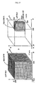
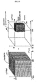
- FIG. 6 shows an example of the LUT 15c.
- the LUT 15c maintains RGB data each containing values 0 through 255. Each color provides 256 gradations.
- the CMYKlclm data has an increased gradation range. That is to say, each CMYKlclm color can be more finely tuned.
- the embodiment decreases the number of reference points instead of increasing the gradation range for the CMYKlclm data to keep the limit of the storage capacity needed to store the LUT 15b.
- the LUT 15c just needs to be able to decrease the number of reference points and increase the gradation range. It is possible to provide various gradation ranges as well as a gradation range of 1024 gradations for CMYKlclm data as available in the LUT 15c according to the embodiment.
- FIG. 9 shows how to vary the gradation range and the number of reference points in a plurality of LUTs so as not to exceed the storage capacity of the LUT 15b.
- FIG. 9 shows the number of color components in the CMYKlclm data and the gradation range out of two pieces of color image data to be associated with each other in each LUT. There are six color components. As mentioned above, the embodiment provides the sRGB gradation range of 256 gradations and three color components. FIG. 9 is configured to give no change to sRGB.
- the number of reference points and the gradation range for LUTs may be determined by increasing or decreasing the gradation range in accordance with the accuracy needed for the color conversion and by increasing or decreasing the number of reference points in accordance with areas in a color space needed for the color conversion.
- the present invention may be configured to not only increase the above-mentioned gradation range of CMYKlclm data from specified 256 gradations, but also increase the gradation range of sRGB data from specified 256 gradations.
- the printer 40 uses an ink set other than six colors, the number of color components becomes other than six. If CMYK data is used, for example, the number of colors becomes four. If DY is added to CMYKlclm, the number of colors becomes seven.
- the above-mentioned description is provided on the basis of the total information amount for the LUT 15b.
- the embodiment is configured to increase or decrease the number of reference points and the gradation range in the other LUT so as not to exceed the total information amount.
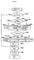
- the halftone process module 21c performs a halftone process that converts each dot's CMYKlclm gradation to be expressed in the recording density of ink droplets.
- the halftone process module 21c generates head drive data to apply ink at the recording density after the conversion at step S220.
- the print data generation module 21d receives the head drive data and rearranges it in the order used on the printer at step S230.
- the printer 40 is mounted with a jet nozzle array (not shown) as an inkjet device. Since a plurality of jet nozzles is parallel provided on the nozzle array along a vertical scanning direction, the nozzle array simultaneously uses data that is separated from each other by several dots along the vertical scanning direction.
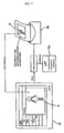
- the display 18 in FIG. 11 displays a screen for executing the APL 25.
- the image data 15a is stored in the RAM 14.
- a process by the display DRV 23 displays an image A based on the image data 15a on the display 18.
- the APL 25 is capable of performing various retouches for the image A displayed on the display 18 and giving an instruction to print the image A.
- the screen for executing the APL 25 in FIG. 11 shows a situation to read the image data 15a stored in the HDD 15 and issue a print instruction. Using the mouse 32, a user can select a print tab from the file menu and issue the print instruction.
- the LUT 15c increases the gradation range of CMYKlclm data, it is possible to define accurate gradation values for reference points in the LUTs.
- the present invention can improve not only the gradation value accuracy of reference points in the LUTs, but also the color conversion accuracy in the color conversion module 21b. That is to say, a linear interpolation is used to compute the correspondence between any colors for color conversion by referencing reference points in the LUTs. Further, the LUTs according to the present invention also improve the accuracy of the linear interpolation.
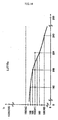
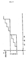
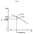
- FIG. 15 is an explanatory diagram illustrating a manner of computing the correspondence between sRGB and CMYKlclm gradation values by means of a linear interpolation.
- FIG. 15 further enlarges an area near sRGB gradation values 208 and 224 in FIG. 13.
- the correspondence for any color is determined by three-dimensionally observing LUT reference points and performing a linear interpolation using a triangular pyramid comprising the reference points. The two-dimensional description is provided here based on FIG. 15 for simplicity.
- the LUT 15b allocates gradation value 41 for the lc ink to both sRGB gradation values 208 and 224.
- the configuration to increase the ink gradation range greatly contributes not only to accuracy improvement of the highlighted portion, but also to accuracy improvement of medium-brightness areas and a shadow portion. Since a large amount of K ink is ejected to the shadow portion, saturation changes are hardly perceptible to human eyes. On the other hand, even slight changes in the brightness can be perceived. It is necessary to control fine brightness gradations so as to obtain printout results with high image quality. Since the present invention highly accurately defines CMYK ink's gradation values, the present invention also can greatly contribute to accuracy improvement of the shadowportion.
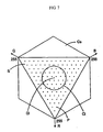
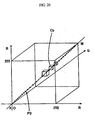
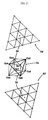
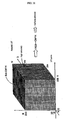
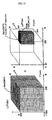
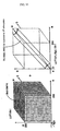
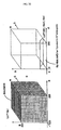
- FIG. 19 extracts lattice points P2 at positions corresponding to vertexes and sides and a center G12 of a hexagon formed around the center G12 of a cross section S2.
- the lattice points P2 can be defined at any positions independently of the reference points in the LUT 15b. It is possible to extract lattice points approximately symmetric with reference to the center G12, making it possible to more easily cover a monochrome area according to the present invention.
- the color solid narrows at both ends of the gray axis. Modifications can be appropriately made to both ends in such a manner as to narrow an interval between the lattice points P1 and P2 or incorporate lattice points by deforming the square lattice or the hexagonal lattice.
- the present invention can configure the sixth embodiment so as to suppress the necessary storage amount and enable highly accurate printing.
- the sixth embodiment controls printing by using data that highly accurately defines colors for part of a color space.
- the sixth embodiment can be implemented by a configuration similar to the hardware scheme as shown in FIG. 1. When the hardware uses the configuration in FIG. 24, it is possible to implement printing by using a color conversion table capable of highly accurate color conversion.
- the mutually corresponding parts in FIGS. 24 and 2 are designated by the same reference numerals. While the first embodiment has described the use of six ink colors for the printer 40, the sixth embodiment will describe the use of four ink colors.
- the LUT 15d1 has more reference points than the LUT 15c1.
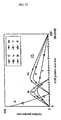
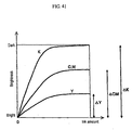
- FIG. 41 diagrams an effect of improving the accuracy when colors are defined in 16-bit gradations.
- the abscissa indicates the ink ejection amount.
- the ordinate indicates the brightness of printout on white paper with the corresponding ink ejection amount for each of CMYK inks.
- decreasing the ink amount increases the brightness.
- Increasing the ink ejection amount decreases the brightness.
- the variation graph shows an upward parabola for each of all the ink colors. At a high brightness area, a slight increase in the ink ejection amount rapidly increases the brightness. However, a low brightness area suddenly causes very small changes in the brightness variation against an increase in the ink ejection amount.
- the CMYK threshold value determination section 21b determines whether or not there is available an ink whose ej ection amount is 50% or more of the maximum ejection amount. If there is available an ink whose ejection amount is 50% or more of the maximum ejection amount, the CMYK threshold value determination section 21b is configured so that the spline interpolation section 21bs2 performs an interpolation for the corresponding RGB data to convert it into CMYK data. If there is not available an inkwhose ejection amount is 50% or more of the maximum ejection amount, the CMYK threshold value determination section 21b is configured so that the linear interpolation section 21b12 performs an interpolation for the corresponding RGB data to convert it into CMYK data. Of course, both interpolations reference the rebuild LUT 14c.
- the LUT defining colors in 16-bit gradations and the LUT having high density reference points provide remarkable effects at the highlighted portion and the shadow portion, respectively.
- the LUT defining colors in 16-bit gradations also improves the color conversion accuracy at the shadow portion.
- the LUT having high density reference points also improves the color conversion accuracy at the highlighted portion.
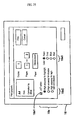
- the display contents of the print property are not limited to the category of the highlight, the shadow, and the like as shown in FIG. 25. Instead, it may be preferable to allow not only selection of the high accuracy as mentioned above, but also selection of a 16-bit LUT, a high density LUT, and the like more explicitly. Of course, it may be preferable to be able to select not only four color areas, but also more or fewer areas.
- Reference points to be defined in the LUT are not limited to those described above. It is possible to change the number of reference points, use unevenly spaced lattice points in the color space as reference points, etc.
- the present invention according to claim 4 can highly accurately perform a color conversion for an image containing a flesh color or its peripheral colors.
- the present invention according to claim 13 can allow a second image device to accurately reflect an effect of high accuracy color conversion according to the present invention.
- the present invention according to claim 25 can create a color conversion table that can highly accurately convert a specific color defined in a specified original table.
- the present invention according to claim 32 can generate a color conversion table capable of accurately expressing fine changes in low brightness colors.
- the present invention according to claim 33 can generate a color conversion table capable of accurately expressing fine changes in low saturation colors.
Landscapes
- Engineering & Computer Science (AREA)
- Physics & Mathematics (AREA)
- General Physics & Mathematics (AREA)
- Theoretical Computer Science (AREA)
- Multimedia (AREA)
- Signal Processing (AREA)
- Color Image Communication Systems (AREA)
- Image Processing (AREA)
- Facsimile Image Signal Circuits (AREA)
- Color, Gradation (AREA)
Abstract
A one-dimensional LUT has been incapable of color matching. A three-dimensional LUT has been incapable of ensuring a color conversion accuracy enough to reproduce fine changes in color tone on a monochrome image. It has been impossible to suppress a storage capacity for a color conversion table by ensuring the accuracy. <??>There is provided a color conversion table which has a plurality of pieces of reference color image data making correspondence between color data for a first image device and color data for a second image device and comprises a specified total information amount. The color conversion table is used to distribute the reference color image data over a prescribed area in a specified color space. Color data information for each reference color image data is increasedmore than a specified amount within a limit of the specified total information amount. Further, a color conversion table is created using an original table which highly accurately defines colors in part of the color conversion table. If these color conversion tables are referenced for color conversion, it is possible to suppress the storage capacity, provide color matching, and perform high accuracy color conversion. <IMAGE>
Description
The present invention relates to a medium recording
a color conversion program, a medium recording color conversion
table data, a color conversion apparatus, a color conversion
method, a color conversion program, a color conversion table,
a medium recording a color conversion table creation program,
a medium recording a interpolation program, a color conversion
table creation program, an interpolation program, a color
conversion table creation apparatus, an interpolation apparatus,
a color conversiontable creation method, an interpolation method,
a partial color conversion table, a printing apparatus, and a
printing method.
A process of printing a monochrome image references
a one-dimensional LUT (lookup table) or a three-dimensional LUT
to convert RGB data (R: red, G: green, B: blue) on a display
into CMYKlclm data (C: cyan, M: magenta, Y: yellow, K: black,
lc: light cyan, lm: light magenta) and the like used on a printer.
The one-dimensional LUT maintains correspondence between
gradation value data of the monochrome image as 256 gradations
of brightness components and gradation values of CMYKlclm ink.
The three-dimensional LUT is similar to an LUT used for the color
conversion of ordinary color images. The three-dimensional LUT
evenly divides an sRGB to form cubic lattices and maintains
correspondence between RGB data and CMYKlclm data at a given
lattice point.
The above-mentioned conventional color conversion
program has the following problems.
That is to say, the one-dimensional LUT is incapable
of color matching. The three-dimensional LUT may not be able
to ensure the sufficient color conversion accuracy to reproduce
fine color tone changes in a monochrome image. Specifically,
monochrome images include not only strictly achromatic images,
but also images having low-saturation colors provided with
various color tones such as warm or cool tones. The
one-dimensional LUT is capable of printing various color tones
by previously creating LUTs for a warm tone and the like. However,
the LUT itself contains data comprising only brightness
components, not RGB color components. Accordingly, there is
no color matching between the monochrome image displayed on a
display and the color as a print result. There has been a need
for repeating trial and error for the purpose of printing
user-specified colors.
On the other hand, the three-dimensional LUT itself
contains data of RGB components. When a monochrome image, i.e.,
having the warm tone, is displayed on the display for printing,
the printing is available in a color approximate to the color
of the displayed monochrome image. However, the conventional
LUT defines CMYKlclm gradation values as 256-gradation data.
There have been cases where the use of these gradation values
cannot reproduce fine changes in color tones of monochrome images.
Simply increasing the number of gradations for CMYKlclm data
unnecessarily increases the capacity for storing the LUT.
Generally, there is a need for improving the accuracy
of color conversion along with the recent trend of improving
the printer performance and increasing the amount of information
about image colors. However, just increasing the amount of
information about the color conversion table unnecessarily
increases the storage capacity of hard disks and the like for
storing data. There is a little need for high color conversion
accuracy for all colors in an image. Just increasing the accuracy
for specific colors can greatly improve the image quality. For
this reason, it is unpreferable to uniformly increase the amount
of information about the color conversion table stored on hard
disks and the like.
The present invention has been made in consideration
of the foregoing. It is therefore an object of the present
invention to provide a medium recording a color conversion
program, a medium recording color conversion table data, a color
conversion apparatus, a color conversion method, a color
conversion program, a color conversion table, a medium recording
a color conversion table creation program, a medium recording
a interpolation program, a color conversion table creation
program, an interpolation program, a color conversion table
creation apparatus, an interpolation apparatus, a color
conversion table creation method, an interpolation method, a
partial color conversion table, a printing apparatus, and a
printing method capable of increasing color matching capability
and the number of gradations and suppressing the necessary
storage capacity at the same time and performing color conversion
at a high precision.
In order to achieve the above-mentioned objects, the
present invention according to claim 1 is configured to provide
a medium recording a color conversion program which allows a
computer to perform a color conversion function for the purpose
of converting first color image data used for a first image device
into second color image data used for a second image device in
such a manner as to previously store reference color image data
as a color conversion table defining correspondence between both
color image data in a specified storage area and to perform color
conversion by referencing the color conversion table, wherein
the color conversion function exclusively uses a prescribed area
in a color space for making correspondence between the first
color image data and the second color image data and performs
color conversion by referencing a color conversion table which
improves accuracy of the correspondence within the area.
In the present invention configured as mentioned above
according to claim 1, a specified storage area previously stores
the color conversion table which defines correspondence between
first color image data used for the first image device and second
color image data used for the second image device. The color
conversion function references the color conversion table to
perform color conversion. Here, the a color conversion table
exclusively uses a prescribed area in a color space for making
correspondence between the first color image data and the second
color image data to improve accuracy of the correspondence within
the area.
That is to say, it is unnecessary to use all color
areas for the first image device and the second image device
so as to perform color conversion for an image with limited
available colors. Accordingly, even if the color conversion
table exclusively uses the area capable of color conversion for
that image's colors as an area in the color space for making
correspondence between the first color image data and the second
color image data, the color conversion is available for colors
within the area. The storage area saved by the limitation is
distributed to areas for specifying colors. In this manner,
it is possible to more highly accurately define color image data
in the area. Accordingly, the color conversion accuracy
improves. Though the area is limited to a prescribed area in
the color space, the color correspondence is defined
three-dimensionally. In this manner, it is possible to directly
ensure the color correspondence between the first and second
image devices with respect to colors within the limited area.
The color conversion is available by keeping color matching
active without the need for a process of converting three-color
components into brightness components.
The present invention according to claim 2 is
configured to provide a medium recording a color conversion
program which has a plurality of pieces of reference color image
data andallows a computer to perform a color conversion function
of referencing a color conversion table comprising a specified
total information amount to convert first color image data used
for a first image device into second color image data used for
a second image device, wherein the color conversion function
distributes the reference color image data over a prescribed
area in a specified color space and performs color conversion
by referencing a color conversion table which increases color
data information about each reference color image data over a
specified amount within a limit of the specified total
information amount.
In the present invention configured as mentioned above
according to claim 2, the color conversion function references
the color conversion table having a plurality of pieces of
reference color image data maintaining correspondence between
color data for the first image device and color data for the
second image device and converts the first color image data used
for the first image device into the second color image data used
for the second image device. Here, there is a limitation on
the total information amount in the color conversion table.
However, the color conversion table distributes the reference
color image data over the prescribed area in the specified color
space. In this manner, the color data information about each
reference color image data is increased over a specified amount
within the limit of the specified total information amount.
Though the reference color image data distributes over
the prescribed area in the color space, the data information
amount exceeds the specified amount with respect to colors in
the area. Consequently, the high accuracy color conversion is
available for colors in the prescribed area. Though the color
data information amount for reference color image data is
increased, there is a limitation on the distribution area for
the reference color image data. Accordingly, the color
conversion table can be defined without increasing the storage
capacity needed for storing the color conversion table over the
limitation on the total information amount. Also in this case,
the correspondence is defined by the reference color image data
in the three-dimensional space. In this manner, it is possible
to directly ensure the color correspondence between the first
and second image devices with respect to colors within the
prescribed area in the color space. The color conversion is
available by keeping color matching active without the need for
a process of converting three-color components into brightness
components.
The limitation on the total information amount in the
color conversion table depends on relative relationship among
various factors. There is not an absolute limitation to be
assumed for all cases. That is to say, it may be preferable
to use a conventional three-dimensional LUT as a reference and
use the storage capacity for storing the LUT as a limitation.
When a specific RAM area is available, the capacity of the
available area may be used as a limitation. When the color
conversion program according to the present invention is executed
on a printer and the like in a standalone manner, it may be
preferable to use the capacity of an available ROM area provided
for the printer as a limitation.
In any of claims 1 and 2, various known techniques
can be used for referencing the reference color image data for
color conversion. For example, an interpolation operation and
the like can be used to compute color image data at any point
from the reference color image data. The color conversion table
may maintain one-to-one correspondence between color image data
for the first image device and color image data for the second
image device. The color conversion table may maintain
correspondence between both via the color conversion into the
absolute color space.
The color conversion table can use various color spaces.
When the table defines one-to-one correspondence between a color
area for the first image device and a color area for the second
image device, it is possible to employ color areas used for these
devices, e.g., an RGB color specification space and CMY-based
color specification spaces such as CMY, CMYK, CMYKlclm,
CMYKlclmDY (dark yellow), and the like. When the table defines
the correspondence via the color conversion into the absolute
color space, it may be preferable to maintain correspondence
among the Lab color specification space, the RGB color
specification space, and the CMY-based color specification
spaces. Further, there is no limitation on the first and second
image devices. These devices may process specified images using
color image data. For example, various image devices are
available such as a display, a printer, a scanner, a digital
camera, and the like. The first and second image devices need
not be provided independently. For example, a fax machine can
be considered to be a combination of a scanner as the first image
device and a printer as the second image device. The present
invention can be applied to such fax machine.
In the present invention according to claim 3, the
prescribed area in a color space is a specified monochrome area
including a low saturation area. That is to say, the present
invention uses a low saturation area in the color space as a
prescribed area. Accordingly, the monochrome area includes not
only strictly achromatic areas, but also an image which appears
to be monochrome for human eyes but has a certain degree of
saturation. The present invention can highly accurately
perform color conversion for such image.
More particularly, the monochrome area includes
various monochromes such as a sepia image that is generated by
slightly emphasizing an R component and suppressing a G component
against the neutral gray R=G=B in the RGB three primary colors,
a warm black tone monochrome based on the warm-color gray, a
cool black tone monochrome based on the bluish gray, etc. Human
eyes are sensitive to a fine color variation in such monochrome
images. An unnatural monochrome image may result from
inconsistency in the color tone due to an error of the color
conversion accuracy. Devotees of monochrome photos are very
particular about fine color tones and request no inconsistency
in an intended color tone. Accordingly, the use of the
configuration according to the present invention can
appropriately satisfy requests for monochrome images that highly
accurately reproduce fine color tones.
In the present invention according to claim 4, the
prescribed area in a color space is configured to be an area
containing a flesh color. When the present invention attaches
importance to the conversion of colors approximate to the flesh
color and defines the flesh color and its peripheral area as
a prescribed area, the high accuracy color conversion is
available for the flesh color and near flesh colors. The flesh
color is especially often used for human faces. If the flesh
color is subdued or is subj ect to an unsmooth change in the color,
the image quality appears to be very degraded. The present
invention can express the very smoothly changing flesh color
by highly accurately converting the flesh color, providing an
image with excellent image quality.
Here, an area including the flesh color just needs
to satisfy the following requirements. That is to say, ensuring
an area containing the flesh color in the color space improves
the accuracy of correspondence between the fist and second color
image data for the flesh color and its peripheral colors.
Alternatively, it is necessary to increase color data information
about the flesh color and its peripheral colors using the total
information amount in the color conversion table as a limitation.
It is possible to change the prescribed area size in accordance
with colors needed as near flesh colors, the total information
amount, and the image type.
In the present invention according to claim 5, the
prescribed area in a color space is configured to be an area
containing a blue color. When the present invention attaches
importance to the conversion of the blue and near blue colors
and defines the blue color and its peripheral area as a prescribed
area, the high accuracy color conversion is available for the
blue color and near blue colors. Aprinting apparatus may provide
a wider color area than a display or a digital camera particularly
with respect to the blue color and near blue colors. It is
possible to perform high accuracy color conversion and provide
a more brilliant result using a wider color area. Here, also,
an area including the blue and near blue colors just needs to
satisfy the following requirements. That is to say, an area
containing the blue and near blue colors improves the accuracy
of correspondence between the fist and second color image data.
Alternatively, it is necessary to increase color data information
about the blue and near blue colors using the total information
amount in the color conversion table as a limitation. It is
possible to change the prescribed area size in accordance with
colors needed as near blue colors, the total information amount,
and the image type. Of course, the present invention can use
the prescribed area comprising an area other than the monochrome
area including a low saturation area and the area including the
flesh color or the blue color. The prescribed area can be a
red area for color conversion of, e.g., an image of the setting
sun or can be a green area for color conversion of, e.g., an
image of woods.
In the present invention according to claim 6, there
are several to over ten pieces of reference color image data
around a specified axis in a specified color space. The present
invention just needs to limit a distribution area for the
reference color image data and increase the data about colors.
Though there is no particular limitation on the number of pieces
of reference color image data in the color conversion table,
it is sufficient to provide several toover ten pieces of reference
color image data around a specified axis in many cases. For
example, an achromatic axis in the color space corresponds to
the specified axis when a color conversion table is created for
processing a monochrome image including the low saturation area.
Extracting several to over ten pieces of reference color image
data around the achromatic axis can define the color conversion
table that is applicable to almost all monochrome images. Here,
straight lines in various color spaces correspond to the
achromatic axis, e.g., the R=G=B line in the RGB space, the C=M=Y
line in the CMYK space, and the L axis in the Lab space.
For example, a blue axis in the color space corresponds
to the specified axis when a color conversion table is created
for processing an image including the blue color. It just needs
to extract several to over ten pieces of reference color image
data around the blue axis that corresponds to a straight line
set to R=G=0 and any value for B in the RGB space, for example.
When a color conversion table is created for processing an image
containing the flesh color, let as assume a specified curve across
the area containing the flesh color. Using this curve as the
specified axis, it just needs to extract reference color image
data around this axis.
In the present invention according to claim 7, the
reference color image data distributes from a specified axis
in a specified color space within a specified gradation value.
The present invention just needs to limit a distribution area
for the reference color image data and increase the data about
colors. Though there is no particular limitation on the distance
from the specified axis, it is possible to easily extract the
reference color image data in consideration for gradation values
from the specified axis. For example, it just needs to extract
lattice points for 256-gradation data within 50 gradations from
the specified axis. The specified axis here is the same as that
described above.
Though there is no particular limitation on the manner
of selecting the reference color image data, the present
invention according to claim 8 provides a preferred example.
The reference color image data is formed by excluding lattice
points other than those in the prescribed area with respect to
cubic lattice points formed by almost evenly dividing an almost
entire area in a specified color space. Coordinates in the color
space can be very easily defined by approximately evenly dividing
almost all areas in the color space. The reference color image
data canbe easily extracted from the prescribed area by excluding
unnecessary coordinates from the defined coordinates. A
conventional method of creating LUTs uses the technique of
approximately evenly dividing almost all areas in the color space.
Accordingly, the reference color image data according to the
present invention can be provided by excluding reference color
image data for the conventional LUT.
In the present invention according to claim 9, the
reference color image data is subject to a change in the
distribution density depending on brightness in a specified color
space. As mentioned above, the color conversion accuracy
increases by improving the accuracy of the correspondence in
the prescribed area or increasing the color data information.
However, the prescribed area may request different color
conversion accuracies. For the purpose of solving this problem,
the brightness in the color space is controlled to change the
distribution density of the reference color image data and to
increase the density in an area that requires the high accuracy
color conversion. In this manner, performing an interpolation
operation or the like for a specific color in the area can provide
high accuracy color conversion.
The present invention according to claim 10 provides
a preferred example of changing the density of reference color
image data in accordance with the color space brightness so that
the reference color image data densely distributes in a high
brightness area. That is to say, human eyes can easily perceive
saturation changes of colors in the high brightness area. It
is often necessary to reproduce fine color variations. Densely
distributing the reference color image data in the high
brightness area can faithfully reproduce fine color variations
in such area.
When an inkjet printer is used as the image device,
it often uses only CMYK inks or lm, lc, and Y inks for colors
in the high brightness area. In addition, the ink ejection amount
is small. Accordingly, it is necessary to express color
variations due to gradation value changes by means of the ink
amount change. Increasing the reference color image data in
this area can highly accurately convert colors that use a few
inks and a small amount of ejection. It is possible to faithfully
reproduce fine color variations.
In the present invention according to claim 11, the
reference color image data densely distributes in a low
brightness area. While human eyes hardly perceive saturation
changes of colors in the low brightness area, human eyes can
sensitively perceive brightness changes. Accordingly, it is
important to accurately control the ejection amount of CMYK or
K ink also for colors in the low brightness area. Increasing
the reference color image data in the low brightness area can
highly accurately convert low brightness colors, making it
possible to control fine brightness gradations.
The present invention according to claim 12 provides
specific examples of improving the correspondence in a prescribed
area and increasing the color data information. In the present
invention, the first color image data and the second color image
data contain gradation value data for color components either
or both the first color image data and the second color image
data have a larger gradation range than 256 gradations. In many
cases, an image device expresses color components of color image
data with 256 gradations. In addition, three or more color
components are combined to express an intended color. When the
reference color image data defines correspondence between the
first and second color image data, increasing the gradation range
more than 256 gradations can improve the accuracy of
correspondence in a specified area and increase the color data
information. As a result, the color conversion accuracy can
be further improved.
Here, the gradation range may be increased more than
256 gradations for either or both the first and second color
image data. The first color image data may define display colors.
The second color image data may define printer colors. In this
case, it is possible to increase gradation values more than 256
gradations for both. However, in many cases, increasing
gradation values more than 256 gradations just for either can
sufficiently provide an effect of improving the color conversion
accuracy. Since the color image data is often processed on a
computer, it is preferable to increase the gradation range on
a double basis when gradation values are increased more than
256 gradations. While 256 gradations can be expressed in 8-bit
data, it is preferable to expand the gradation range to 512
gradations (9 bits), 1024 (10 bits), and so on.
In the present invention according to claim 13, the
second image device is a printing apparatus and the second color
image data defines an ink ejection amount of the printing
apparatus. When the color conversion is performed by improving
the accuracy of correspondence in the prescribed area or
increasing the color data information, the second image device
needs to have sufficient capability of reflecting a result of
the accurate color conversion. Recent printing apparatuses
provide very high output resolutions and use halftoning to
express gradations. Many printing apparatuses have sufficient
capability of expressing gradations finer than 256 gradations
for color output. When the present invention is applied to a
printing apparatus as the second image device, the device can
exactly reflect an effect of high accuracy color conversion
according to the present invention.
Of course, the above-mentioned color conversion
program may be recorded on magnetic recording media, magnetic
optical media, or any recording media that will be developed
in the future. Obviously, the same applies to replica stages
such as for primary or secondary replicas. Unlike the
above-mentioned media, a communication line can be used to
deliver the color conversion program. In this case, the
communication line functions as a transmission medium for using
the present invention. When the function of the color conversion
program is implemented partly by software and partly by hardware,
such configuration does not deviate completely from the concept
of the invention. Part of the function may be stored in a
recording medium and may be appropriately read out for execution
as needed.
As mentioned above, the color conversion function
references the reference color image data during color conversion.
If the reference color image data is provided as color conversion
table data, it can be used for a general-purpose color conversion
program. This makes it possible to perform the color conversion
according to the present invention. Accordingly, it is possible
to consider that the technical concept of the present invention
is applied to the table itself as a collection of representative
points to be referenced. Like the invention according to claims
14 and 15, the present invention can be specified as a medium
recording color conversion table data that is referenced during
color conversion and comprises reference color image data
distributed over a prescribed area in the color space. Of course,
the present invention can be embodied as a medium recording the
color conversion table data according to claims 3 through 13.
Further, it can be easily understood that the color
conversion program can be embodied on a computer and the present
invention is applicable as a substantial apparatus including
such computer. Accordingly, the invention according to claims
16 and 17 provides basically the same operations. It is also
possible to embody the color conversion apparatus according to
claims 3 through 13. Obviously, the color conversion apparatus
may be embodied independently or along with the other methods
in such a manner as to be installed in a certain device. The
concept of the invention is not limited thereto but may be
otherwise variously embodied and modified appropriately.
The color conversion program references the reference
color image data according to the present invention to perform
processes naturally on the basis of a procedure according to
the present invention. It can be easily understood that the
present invention is also applicable as a method. Accordingly,
the invention according to claims 18 and 19 provides basically
the same operations. It is also possible to embody the color
conversion method according to claims 3 through 13. That is
to say, the present invention is not necessarily limited to a
substantial medium but is also effective as its method. Of course,
the present invention functions as not only a medium recording
the color conversion program, but also a color conversion program.
The invention according to claims 20 and 21 provides basically
the same operations. It is also possible to embody the color
conversion program according to claims 3 through 13. Further,
it is possible to consider that the technical concept of the
present invention is applied to the table itself as a collection
of representative points to be referenced. Like the invention
according to claims 22 and 23, the present invention can be
specified as a color conversion table. Of course, it is also
possible to embody the color conversion table according to claims
3 through 13.
The invention according to claim 24 is configured to
provide a medium recording a color conversion table creation
program to create a color conversion table which defines
correspondence between first color image data used for a first
image device and second color image data used for a second image
device with respect to a plurality of reference points, wherein
the program allows a computer to implement: an original table
storage function which stores an original table having part of
information in a color conversion table to be created; and a
color conversion table generation function which can generate
the color conversion table by combining at least two original
tables defining different color accuracies and by supplementing
information missing from the plurality of reference points.
This signal is generated as follows. Each 50 bps
transmission data is spectrum-spread by means of a PN code
(spread code) that has a pattern unique to each GPS
satellite and features a transmission signal rate of 1.023
MHz and a code length of 1023. The spectrum spread signal
is a C/A code whose carrier has a frequency of 1575.42 MHz.
This carrier is BPSK modulated to generate the
above-mentioned high-frequency GPS signal.
The invention configured as mentioned above according
to claim 24 creates a color conversion table that defines
correspondence between first color image data used for the first
image device and second color image data used for the second
image device for a plurality of reference points. The original
table storage function stores an original table that has part
of information in the color conversion table to be created. The
color conversion table generation function uses at least two
original tables having different accuracies of colors defined
in the original table. The above-mentioned color conversion
table is created by combining these original tables and
supplementing information missing from the plurality of
reference points.
Generation of the color conversion table uses a
combination of at least two original tables having different
color accuracies. If the color conversion table is created by
using information about colors included in the high accuracy
original table, it is possible to increase the color conversion
accuracy contained in the high accuracy original table. The
high accuracy original table is configured to define
correspondence for colors that remarkably exhibit an effect of
improving the image quality in response to an increase in the
conversion accuracy. In this manner, if the color conversion
accuracy is unchanged for colors other than the relevant color,
human eyes can perceive an effect of remarkably improving the
image quality. That is to say, it is possible to suppress the
storage capacity and improve the conversion accuracy at the same
time.
Specifically, it has been a conventional practice to
reference an original table comprising 17**3 reference points
stored in a hard disk, where x**y signifies x to the yth power
hereinafter. An interpolation operation is performed to
interpolate reference points and generate a color conversion
table comprising 33**3 reference points. In addition, the
present invention provides an original table that has a higher
color accuracy and fewer reference points than the
above-mentioned original table comprising 17**3 reference
points. The present invention combines these tables.
Increasing the color accuracy for all the 17**3 reference points
unnecessarily increases the storage capacity needed for the
original table storage function. According to the present
invention, however, information of the original tables
constitutes part of the color conversion table. One of the
original tables provides a higher color conversion accuracy than
the other. The needed storage capacity can be suppressed by
assuming the high accuracy color area to be an intended area.
In addition, it is possible to improve the accuracy of the color
conversion to be performed for the color conversion table
associated with the intended color. Consequently, the image
quality can be improved.
Of course, there is no particular limitation on the
number of reference points in the original table, the number
of color components for specifying colors, and the number of
bits for expressing colors in gradations. The original tables
just need to have part of the color conversion table to be created
during the color conversion. There needs a difference between
accuracies for at least two original tables. The color
conversion table generation function just needs to be able to
supplement information missing from a plurality of reference
points provided for the color conversion table. The present
invention also includes a configuration of increasing the number
of reference points, e.g., by means of an interpolation operation
and a configuration of increasing the number of bits for
expressing colors in gradations.
The invention according to claim 25 provides an example
of the above-mentioned original tables. According to the
invention, the original table storage function stores at least
two original tables having different gradations for color image
data. If the original tables have different numbers of
gradations for expressing colors associated with the color image
data, the table having more gradations can define an intended
color more accurately. Therefore, the color conversion table
generation function cangenerate a color conversion table capable
of highly accurately converting colors in the original table
that defines colors with many gradations.
The invention according to claim 26 provides an example
of the above-mentioned original tables. According to the
invention, the original table storage function stores at least
two original tables having different reference point densities
for defining correspondence. The original table or the color
conversion table does not define the correspondence of a specific
color, but defines the reference point thereof. During the color
conversion, an interpolation operation or the like is performed
to compute the correspondence of the specific color.
When the color conversion is used to compute color
image data for a specific color, the following can be presumed.
That is to say, when more reference points are found around a
color to be converted and are positioned more approximately to
it, the conversion accuracy of the interpolation operation or
the like improves, highly accurately defining the color. In
consideration for this, assigning different reference point
densities to two original tables can provide both tables with
different color accuracies. The table having a higher reference
point density can more accurately define an intended color than
the other. Therefore, the color conversion table generation
function can generate a color conversion table capable of highly
accurately converting colors in the original table that has a
higher reference point density.
The invention according to claim 27 provides a
configuration example of assigning different reference point
densities to the original tables. According to the invention,
one of the original tables has a higher reference point density
than a reference point density in the other original table and
has a lower reference point density than a reference point density
in the color conversion table. As mentioned above, the two
original tables are assigneddifferent reference point densities.
If the reference point density of the original table is higher
than that of the color conversion table that is generated by
the color conversion table generation function, however, some
of the reference points are not reflected on the color conversion
table. It is sufficient to set the upper bound of the original
table's reference point density equal to the color conversion
table's reference point density.
As set forth in claims 26 and 27, the original tables
are configured to have different reference point densities. In
this configuration, the table having a higher reference point
density is assigned fewer reference points than the table having
a lower reference point density. This makes it possible to
suppress the storage capacity needed for the original table
storage function. Accordingly, it is possible to improve the
color conversion accuracy without unnecessarily increasing the
storage capacity.
In the invention according to claim 28, the second
image device is configured to be a printing apparatus capable
of using a plurality of colors of ink. Further, the original
table storage function is configured to express a gradation
change of a specified color component in the second color image
data by identifying a color component using a smaller number
of inks than the other color components and, for this color
component, storing an original table having a higher accuracy
than for the other color components.
When the printing apparatus expresses a color, dark
and light inks may be used for a certain color component. While
the present printing apparatus normally uses inks comprising
CMYK color components such as cyan, magenta, yellow, and black,
for example, there may be a case of further using an lc (light
cyan) ink for the C ink and an lm (light magenta) ink for the
M ink. When the dark and light inks are used, each of these
types of inks is assigned the same range of gradations as for
the other color components, making it possible to more highly
accurately express colors than the other color components.
When the accuracy is increased for color components
(black and cyan in the above-mentioned example) that use fewer
inks than the other color components, it is possible to create
a color conversion table that can perform the high accuracy color
conversion for these color components. Of course, the accuracy
just needs to be increased for a color that uses a smaller amount
of ink than the other color components. When a light ink is
used for black, the accuracy needs to be increased for colors
other than black. When DY (dark yellow) is used for yellow and
no light ink is used for the C and M inks in the above-mentioned
example, the accuracy needs to be increased for the C and M inks.
When a user can select inks available on the printing apparatus,
it is obviously possible to change color components requiring
the high accuracy depending on the selected inks.
The invention according to claim 29 provides an example
of increasing the accuracy for a specific ink. According to
the invention, the color component using a smaller number of
inks than the other color components is yellow. That is to say,
some of currently available printing apparatuses use the lclm
inks in addition to the CMYK inks. Increasing the accuracy for
the Y ink can generate a color conversion table that can be suitably
used for many commercially available printing apparatuses.
In the invention according to claim 30, the second
image device is configured to be a printing apparatus capable
of using a plurality of colors of ink. Further, the original
table storage function is configured to identify a color
component having a wider range of displayable brightness than
the other color components and stores an original table having
a higher accuracy than the other color components. If the
original table uses only the specified number of reference points
to define a color for the ink of color components having a wide
expressible brightness range, the definition accuracy degrades
relatively to the ink of color components having a narrow
expressible brightness range.
If a small number of reference points are used to define
colors for a portion that causes a nonlinear relationship between
the ink ejection amount and the brightness in the printing
apparatus, the color definition accuracy especially degrades
during an interpolation operation or the like to compute the
ink ej ection amount for reference points other than the specific
reference point. To solve this problem, a higher accuracy is
given to the color component having a wider expressible
brightness range than the other color components. In this manner,
it is possible to create a color conversion table capable of
highly accurately converting the color that exhibits remarkable
nonlinearity.
There can be alternatives to the above-mentioned
configuration of increasing the color accuracy in the original
table in terms of ink colors. It may be preferable to determine
a high accuracy area in terms of a color expressed as a combination
of colors, i.e., an image color. The invention according to
claim 31 provides a specific example. According to the invention,
a high brightness color in one of the original tables is given
a higher accuracy than an accuracy for defining colors in the
other original table.
An image device such as the printing apparatus that
uses the subtractive color mixing only uses a small amount of
ink to express high brightness colors. It is necessary to express
color variations resulting from gradation value changes by means
of changes in the small amount of ink. Accordingly, highly
accurately defining such high brightness colors makes itpossible
to create a color conversion table capable of accurately
expressing fine color changes. Highly accurately defining high
brightness colors in the original table includes not only
defining part of the colors defined in the original table, but
also defining all of the colors defined therein.
In the invention according to claim 32, a low brightness
color in one of the original tables is given a higher accuracy
than an accuracy for defining colors in the other original table.
The amount of ink increases and the brightness decreases on an
image device such as the printing apparatus that uses the
subtractive color mixing. Generally, the increasing amount of
ink is not proportional to the decreasing amount of brightness.
The brightness drastically decreases after the ink amount exceeds
a specified value. The rate of increase in the ink amount
drastically changes mainly at an area of low brightness color.
Such color easily decreases the conversion accuracy for obtaining
image data of any color by means of an interpolation. To solve
this problem, there is provided an original table that highly
accurately defines low brightness colors. The use of such
original table can create a color conversion table capable of
highly accurately converting low brightness colors. Of course,
also in this case, highly accurately defining low brightness
colors in the original table includes attributing the low
brightness to not only part of the colors defined in the original
table, but also all of the colors defined therein.
In the invention according to claim 33 , a low saturation
color in one of the original tables is given a higher accuracy
than an accuracy for defining colors in the other original table.
A low saturation color has hues but appears like almost monochrome
to human eyes. Human eyes are very sensitive to fine color
changes in an image containing a large proportion of such color.
Highly accurately defining such low brightness colors makes it
possible to create a color conversion table capable of accurately
expressing fine color changes.
In the invention according to claim 34, any of or a
combination of a flesh color and its peripheral colors, a blue
color and its peripheral colors, and a red color and its peripheral
colors in one of the original tables is given a higher accuracy
than an accuracy for defining colors in the other original table.
The present invention attributes the high accuracy to some colors
in the color space for saving the storage capacity. Therefore,
the accuracy of the original table should be improved for colors
that remarkably exhibit an effect of improving the accuracy.
Examples such colors include the flesh color and its
specified peripheral colors, the blue color and its specified
peripheral colors, and the red color and its specified peripheral
colors. The flesh color and its specified peripheral colors
are often used for human faces, for example. When the flesh
color is subdued or is subject to an unsmooth color variation,
the image quality appears to be very degraded. Since the present
invention creates a color conversion table capable of highly
accurately converting the flesh color, it is possible to express
the very smoothly varying flesh color and to obtain an image
of excellent image quality.
A printing apparatus may provide a wider color area
than a display or a digital camera particularly with respect
to the blue color and near blue colors. It is possible to perform
high accuracy color conversion and provide a more brilliant
result using a wider color area. A pseudo contour easily occurs
with respect to the blue color and near blue colors and the red
and near red colors constituting an image like a sunset, for
example. In such case, it is possible to prevent occurrence
of a pseudo contour and obtain images of excellent image quality
by generating a color conversion table capable of the high
accuracy color conversion for these colors. In addition to these
colors, of course, the prescribed area can be a green area for
color conversion of, e.g., an image of woods.
As mentioned above, the original table highly
accurately defines high brightness colors, low brightness colors,
the flesh color and its specified peripheral colors, the blue
color and its specified peripheral colors, the red color and
its specified peripheral colors, and the like. In this case,
it is preferable to be able to highly accurately convert intended
colors by suppressing the storage capacity of the original table.
Accordingly, it is possible to change areas containing the colors
in the original table in accordance with the sufficient size
of an area in the color space for well expressing images, the
total information amount available for the original table, types
of images, and the like.
In the invention according to claim 35, the color
conversion table generation function allows a user to select
whether or not to generate a color conversion table by means
of the combination. That is to say, the user can determine
whether or not to generate a color conversion table capable of
highly accurately converting specified colors. When the
present invention is applied to a conventional printing apparatus
or computer, it is possible to provide an option that enables
users to select whether or not to highly accurately convert
specified colors. Accordingly, this increases options for
users. It becomes possible to satisfy various user's needs such
as highly accurately converting specified colors in one case
or performing the color conversion without attributing the high
accuracy to specified colors in another case. When a user is
allowed to select generation of a color conversion table by
combination, it is also possible to prepare a plurality of
original tables with different areas of colors and make the areas
of colors selectable.
In the invention according to claim 36, the selection
enables generation of a color conversion table using at least
two original tables having different gradations for the color
image data, generation of a color conversion table using at least
two original tables having different reference point densities
for defining the correspondence, and generation of a color
conversion table using both of these conditions.
There are provided techniques of improving the
original table accuracy by increasing gradations for color image
data and increasing the reference point density. Either or both
techniques can be performed to generate a color conversion table.
As a result, a user can select the color conversion table from
various choices in accordance with the needed color conversion
accuracy.
In the invention according to claim 37, there are
provided an image data acquisition function to obtain image data
comprising the first color image data and a specific color ratio
computation function to compute a ratio of a specific color to
the obtained image data as a whole. When a ratio computed by
the specific color ratio computation function exceeds a specified
thresholdvalue, the color conversion table generation function,
generates a color conversion table according to the selection
using an original table which highly accurately defines colors
including the specific color.
When a user is allowed to select whether or not to
generate a color conversion table by combination, as mentioned
above, it is possible to provide the color conversion table
according to the present invention as an option. In addition
to this embodiment, it would be convenient if an highly accurate
interpolation is automatically performed without user's
specification. For example, this is implementable by
referencing a proportion of a specific color in the image data
for which the color conversion should be performed. when the
image targeted for the color conversion contains a large
proportion of the specific color, a color conversion table is
createdby combining an original table highly accurately def ining
the specific color and an original table less highly accurately
defining that color. In this manner, the color conversion table
can be used to automatically perform the high accuracy color
conversion for the specific color.
The proportion of the specific color contained is
computed based on image data. Therefore, it is possible to
automatically determine an area capable of high accuracy color
conversion. When the image contains the specific color whose
proportion is greater than a specified threshold value, the
specific color can be highly accurately converted. The high
accuracy color conversion is available on many or important
portions of the image. It is possible to automatically improve
the image quality on the second image device. Various techniques
are available for computing a proportion of a specific color
in image data. An example of such technique is to compute a
histogram for the first color image data in which a specific
color component or a combination thereof has a specified value.
The histogram is then compared with the number of all pixels.
According to the present invention, an interpolation
operation may be performed to find correspondence between any
colors when a color conversion table is created or the color
conversion is performed by referencing the color conversion table.
The accuracy to define colors in the color conversion table itself
is important for improving the color conversion accuracy. In
addition, the accuracy of the interpolation operation is also
important during the color conversion. Generally, a nonlinear
interpolation provides higher accuracy than a linear
interpolation but requires more operation time.
The invention according to claim 38 provides a
preferred example of interpolation operations. According to
the invention, there is provided a medium recording an
interpolation program to store an original table having some
information about a color conversion table to be created, combine
at least two original tables defining different color accuracies
defined in the original table, interpolate information missing
fromthepluralityof referencepoints, andexecuteinterpolation
using either or both an interpolation operation for creating
a color conversion table defining correspondence between first
color image data used for a first image device and second color
image data used for a second image device with respect to a
plurality of reference points and an interpolation operation
for color conversion using the color conversion table. In this
case, the program executes an interpolation operation by
selecting a linear interpolation technique or a nonlinear
interpolation technique in accordance wi th high or lowbrightness
of a color to be referenced during execution of the interpolation
operation.
An interpolation operation is performed when a color
conversion table according to the present invention is created
and when the color conversion is performed with reference to
the color conversion table. Interpolation operation techniques
are configured to be selectable so that interpolations are
changed in accordance with high or low brightness of a color
at the reference point. According to the subtractive color
mixing used for printing apparatuses and the like, high
brightness colors expressed by a small amount of ink maintain
proportional relationship between a change in the ink amount
and a change in the brightness. Even a linear interpolation
can ensure high accuracy and therefore is used from the viewpoint
of a higher operation speed. When the ink amount exceeds a
specified value, however the proportional relationship is not
maintained between a change in the ink amount and a change in
the brightness. Accordingly, the accuracy of the linear
interpolation degrades relatively. To solve this problem, the
present invention performs a nonlinear interpolation (e.g.,
spline interpolation) capable of high accuracy interpolation
operations despite the nonlinear relationship. Consequently,
the high accuracy color conversion can be performed for the entire
image without degrading the operation speed.
Of course, it is possible to add the configuration
according to the present invention to the configuration according
to claims 25 through 37 mentioned above. The invention according
to claim 39 exemplifies a specific configuration to change the
interpolation techniques in accordance with high or low
brightness of a color. According to the invention, the second
color image data defines the amount of ink. In this case, a
nonlinear interpolation is executed when execution of the
interpolation operation references a color to detect that any
of color components or a combination of ink amounts exceeds a
specified threshold value.
For example, a printing apparatus expresses colors
by combining a plurality of colors of inks. In such case, it
is possible to say that increasing the ink amount for each of
color components decreases the brightness of the corresponding
color or that increasing a combination of ink amounts also
decreases the brightness. Therefore, if a threshold value is
checked with respect to the ink amount for each of color components
or for a combination thereof, it is possible to easily change
the interpolation techniques in accordance with high or low
brightness of a color.
The invention according to claim 40 provides another
configuration example of changing the interpolation techniques.
According to the invention, there is provided a medium recording
an interpolation program to store an original table having some
information about a color conversion table to be created, combine
at least two original tables defining different color accuracies
defined in the original table, interpolate information missing
fromthepluralityofreferencepoints, and execute interpolation
using either or both an interpolation operation for creating
a color conversion table defining correspondence between first
color image data used for a first image device and second color
image data used for a second image device with respect to a
plurality of reference points and an interpolation operation
for color conversion using the color conversion table. In this
case, the program executes a nonlinear interpolation when
referencing a color in an original table defining colors with
a relatively low accuracy and executes a linear interpolation
when referencing a color in an original table defining colors
with a relatively high accuracy.
Interpolation operation techniques are configured to
be selectable when a color conversion table according to the
present invention is created and when the color conversion is
performed with reference to the color conversion table. In
addition, the interpolation operation techniques are changed
in accordance with accuracies of the original tables. When the
original table highly accurately defines colors, it is often
possible to satisfactorily maintain the good image quality after
the color conversion. In such case, the linear interpolation
is performed. Even if the original table relatively less
accurately defines colors, performing the nonlinear
interpolation can provide a high accuracy interpolation. The
good image quality can be maintained in accordance with the color
conversion. As a result, the high accuracy color conversion
can be performed for the entire image without degrading the
operation speed. Of course, it is also possible to add the
configuration according to the present invention to the
configuration according to claims 25 through 37 mentioned above.
Of course, the above-mentioned color conversion table
creation program or the interpolation program mentioned above
may be recorded on magnetic recording media, magnetic optical
media, or any recording media that will be developed in the future.
Obviously, the same applies to replica stages such as for primary
or secondary replicas. Unlike the above-mentioned media, a
communication line can be used to deliver the color conversion
program. In this case, the communication line functions as a
transmission medium for using the present invention. When the
function of the color conversion program is implemented partly
by software and partly by hardware, such configuration does not
deviate completely from the concept of the invention. Part of
the function may be stored in a recording medium and may be
appropriately read out for execution as needed.
The present invention functions not only as the medium
recording the color conversion table creation program and the
interpolation program, but also as the color conversion table
creation program and the interpolation program. The invention
according to claims 41 and 43 provides basically the same
operations. It is possible to embody the color conversion table
creation program as set forth in claims 25 through 37 and the
interpolation program as set forth in claim 39.
Further, it can be easily understood that the color
conversion table creation program and the interpolation program
can be embodied on a computer and the present invention is
applicable as a substantial apparatus including such computer.
Accordingly, the invention according to claims 44 and 46 provides
basically the same operations. It is also possible to embody
the color conversion table creation apparatus as set forth in
claims 25 through 37 and the interpolation apparatus as set forth
in claim 39. Obviously, the color conversion apparatus may be
embodied independently or along with the other methods in such
a manner as to be installed in a certain device. The concept
of the invention is not limited thereto but may be otherwise
variously embodied and modified appropriately.
The color conversion table creation program and the
interpolation program reference the reference color image data
according to thepresent invention to perform processes naturally
on the basis of a procedure according to the present invention.
It can be easily understood that the present invention is also
applicable as a method. Accordingly, the invention according
to claims 47 and 49 provides basically the same operations. It
is also possible to embody the color conversion table creation
method according to claims 25 through 37 and the interpolation
method according to claim 39. Further, it is possible to consider
that the technical concept of the present invention is applied
to the table itself as a collection of representative points
to be referenced for creation of the color conversion table.
Like the invention according to claims 50 and 51, the present
invention can be specified as a partial color conversion table.
Of course, it is also possible to embody the color conversion
table according to claims 27 through 37.
Moreover, it is possible to consider that the technical
concept of the present invention is applied to apparatuses and
methods for the color conversion using the color conversion table
created by the present invention. The present invention can
be also specified as the color conversion apparatus and the color
conversion method like the invention as set forth in claims 52
and 53. Of course, it is also possible to embody the color
conversion apparatus and the color conversion method according
to claims 25 through 37. Furthermore, it is possible to consider
that the technical concept of the present invention is applied
to apparatuses and methods for printout using the color
conversion table created by the present invention. The present
invention can be also specified as the printing apparatus and
the printing method like the invention as set forth in claims
54 and 55. Still further, it is possible to consider that the
technical concept of the present invention is applied to
apparatuses and methods for printout using the interpolation
operations according to the present invention. The present
invention can be also specified as the printing apparatus and
the printing method like the invention as set forth in claims
56 and 57.
Embodiments of the present invention will now be
described in the following sequence.
FIG. 1 schematically shows a hardware configuration
of a computer capable of executing a color conversion program
according to the present invention. FIG. 2 shows a schematic
configuration in which the color conversion program is
implemented as a color conversion module 21b on a printer driver
installed in the computer's OS. A computer 10 has a CPU 11 as
the center of processes. The CPU 11 can make access to ROM 13
containing BIOS and the like and to RAM 14 via a system bus 12.
The system bus 12 connects with a hard disk drive (HDD)
15, a flexible disk drive 16, and CD-ROM drive 17 as external
storages. The HDD 15 stores an OS 20, an application program
(APL) 25, and the like which are then transferred to the RAM
14. The CPU 11 accesses the ROM 13 and the RAM 14 as needed
to execute the software. That is to say, the RAM 14 is used
as a temporary work area for executing a variety of programs.
The computer 10 connects with input operation devices
such as a keyboard 31 and a mouse 32 via a serial communication
I/O 19a. The computer 10 also connects with a display 18 for
monitoring via a video board (not shown) . The computer 10 can
connect with a printer 40 via a parallel communication I/O 19b.
While the configuration of the computer 10 is simplified, it
is possible to employ a general configuration as a personal
computer. Of course, the present invention is not limited to
personal computers. While the embodiment uses a so-called
desktop computer, it may be preferable to use notebook or mobile
computers. In addition, the present invention is not limited
to the above-mentioned connection interface between the computer
and the printer 40. It is possible to use various connection
forms such as a serial interface, SCSI, USB connections, and
any connection forms to be developed in the future.
While the HDD 15 stores programs in this example, the
storage medium is not limited thereto. For example, it may be
preferable to use a flexible disk 16a or a CD-ROM 17a. A program
recorded on these recording media is read into the computer 10
via the flexible disk drive 16 or a CD-ROM drive 17 and is installed
into HDD 15. The program is read into the RAM 14 via the HDD
15 to control the computer. The recording media are not limited
thereto. A magnetic optical disk may be used. As a
semiconductor device, it is possible to use nonvolatile memory
such as a flush card. When an external file server is accessed
for downloading via a modem or a communication line, the
communication line works as a transmission medium for using the
present invention.
As shown in FIG. 2 , the OS 20 of the computer 10 according
to the embodiment is installed with a printer driver (PRTDRV)
21, an input device driver (DRV) 22, and a display driver (DRV)
23. The DRV 23 controls display of image data and the like on
the display 18. The input device DRV 22 receives code signals
supplied from the keyboard 31 or the mouse 32 via the serial
communication I/O 19a and accepts specified input operations.
The APL 25 issues a print instruction to drive the
PRTDRV 21. The PRTDRV 21 sends data to the display DRV 23 to
display a UI for entering information needed for printing. FIG.
3 shows a print property screen as the UI. The PRTDRV 21 accepts
various information inputs via the input device DRV 22. The
print property screen in FIG. 3 allows input of various parameters
to be specified for printing. The print property screen contains
various input boxes for entering the number of copies and the
number of pages and various buttons for performing print or cancel
instructions. There is provided an LUT selection box 18a as
one of input boxes at the bottom left of the property screen.
The user can modify the display contents of the LUT selection
box 18a via a pointer or the like using the mouse 32. The LUT
selection box 18a can display available LUTs from which the user
can select an intended LUT.
At the right center of the property screen, there is
provided an image selection box 18b for selecting image types.
Using radio buttons, the user can select a color image or a
monochrome image to be printed. The selection here
automatically selects an appropriate LUT. Obviously, the
above-mentioned print properties are an example. It may be
preferable to display either the LUT selection box 18a or the
image selection box 18b. Further, it is possible to provide
various modifications in such a manner as to generate a specified
alarm when an attempt is made to select a color image from the
image selection box 18b though a color LUT is selected in the
LUT selection box 18a. Moreover, the selection of LUTs can be
variously configured in such a manner as to not only use the
print property screen under control of the PRTDRV 21, but also
display a specified setup screen as one of functions of the APL
25.
In any case, the embodiment can provide printing by
selecting an LUT 15b for ordinary color image printing and an
LUT 15c for monochrome image printing that are previously created
and are saved on the HDD 15. Of course, it is possible to create
different LUTs for media or ink sets available for the printer
40 and make these LUTs selectable. In this embodiment, the image
data 15a is sRGB-standard compliant dot matrix data that
expresses RGB color components in gradations. The LUT is a table
that keeps correspondence between gradation values for the sRGB
and gradation values for six CMYKlclm colors used on the printer
40.
In the embodiment, the sRGB-standard compliant data
is the first color image data used for the first image device
(display 18). The CMYKlclm data is the second color image data
used for the second image device (printer 40) . A set of both
gradation values defined in the LUT is reference color image
data. The monochrome image according to the embodiment includes
low saturated colors that range from neutral gray comprising
achromatic color to warm or cool tones having some degree of
saturations. Accordingly, the LUT 15c maintains correspondence
between R=G=B data as well as data containing adjacent colors
and CMYKlclm gradation values. On the other hand, the LUT 15b
for ordinary color image printing maintains correspondence
between gradation value data evenly distributed over all the
RGB gradation values and CMYKlclm gradation values.
FIG. 4 shows an example of the LUT 15b. As shown in
FIG. 4, the LUT 15b contains RGB data and CMYKlclm data each
containing values 0 through 255. Each color provides 256
gradations (8 bits). For each RGB component of sRGB data,
gradation values are evenly divided into 16 to form reference
points. A color solid defined in sRGB space is formed in the
orthogonal space using axes corresponding to RGB colors. As
shown in FIG. 5, each axis of the color solid is given 17 lattice
points to configure cubic lattices that work as reference points.
Therefore, there are 17**3 reference points in total. The LUT
15b defines correspondence between sRGB data and CMYKlclm data
with reference to 17**3 colors. In FIG. 5, origin 0 indicates
black point K. A vertex opposite origin 0 represents white point
W. Colors along a line (gray axis) connecting both points become
achromatic.
FIG. 6 shows an example of the LUT 15c. As shown in
FIG. 6, the LUT 15c maintains RGB data each containing values
0 through 255. Each color provides 256 gradations. The
CMYKlclm data has an increased gradation range. That is to say,
each CMYKlclm color can be more finely tuned. The embodiment
decreases the number of reference points instead of increasing
the gradation range for the CMYKlclm data to keep the limit of
the storage capacity needed to store the LUT 15b.
The LUT 15c in FIG. 6 has a gradation range of 0 to
1023 (1024 gradations, i.e., 10 bits) for CMYKlclm data. The
LUT 15c requires more storage capacity by two digits in binary
than the LUT 15b. The RAM 14 handles storage information on
a byte basis, i.e., in units of eight bits. It is preferable
to allocate 16 bits for storing 10-bit information from the
viewpoint of the configuration of the RAM 14, a computing speed,
and the like. The embodiment allocates the 16-bit storage
capacity for 10-bit information expressing CMYKlclm data and
requires twice as much storage capacity as the LUT 15b.
Accordingly, the number of reference points is kept to 17**3/2
(approximately 13**3) so as not to exceed the storage capacity
of the LUT 15b. Even if the number of reference points is
decreased, the LUT 15c is used for monochrome image printing
and therefore just needs to have reference points needed for
printing colors included in a monochrome area.
According to the embodiment, reference points in the
sRGB space for the LUT 15c comprise lattice points for R=G=B
and several to over ten lattice points nearby. Specifically,
the reference points for the LUT 15c may include the gray axis
in FIG. 5 and surrounding several to over ten lattice points.
FIG. 7 shows an example. FIG. 7 is a perspective view of the
color solid in the sRGB space of FIG. 5. The color solid is
cutonaplane crossing three points (RGB) = (0,0,255), (0,255,0),
and (255,0,0), and is viewed from the origin 0 along the gray
axis.
A plurality of lattice points P on a cross section
S in FIG. 7 corresponds to cubic lattice points configured by
giving 17 lattice points to each axis of a color solid Cs in
the sRGB as mentioned above. A center G1 of the cross section
S is an intersecting point between the gray axis and the cross
section S. The LUT 15c according to the embodiment assumes a
circle Ci having the center G1 to extract several to over ten
points around the center G1. Lattice points P within the circle
are extracted as reference points for the LUT 15c.
It is possible to consider a cylinder around the gray
axis by assuming the other circles Ci along the gray axis on
the cross sections other than the cross section S. If lattice
points within this cylinder are assumed to be reference points
for the LUT 15c, it is possible to extract lattice points around
the gray axis. The color solid in the sRGB space narrows near
both ends of the gray axis, i.e., the black point K and the white
point W. Lattice points decrease in the cylinder around the
gray axis toward the end from the intersecting point between
the outside periphery of the cylinder and the outside surface
of the color solid. As a solution, it is possible to extract
several points outside the cylinder as reference points at both
ends for adjustment not to decrease the color conversion accuracy
in these areas. Of course, the above-mentioned method of
creating the LUT 15c is an example. Rather than extracting
several to over ten lattice points around the gray axis, it may
be preferable to extract lattice points within a specified
gradation value from the gray axis when the sRGB gradation range
complies with 256 gradations. Further, it is possible to use
various selection methods to be described later.
It is possible to create the LUT 15c by following a
sequence of processes as indicated by a flowchart in FIG. 8.
Since the process needs many computation processes, it is
preferable to perform computation using a computer. The LUT
15c defines the correspondence between sRGB data and CMYKlclm
data in the monochrome area comprising low-saturation colors.
The LUT 15c converts colors represented by sRGB data used for
the display 18 and CMYKlclm data used for the printer 40 into
coordinate values in a Lab space for correspondence between the
sRGB data and the CMYKlclm data in a specified monochrome area
in the Lab space. To create an LUT, the process extracts
reference points for the display 18 at step S100. At this time,
the process extracts lattice points P not only in the cylinder
around the gray axis, but also outside the cylinder at both ends
of the gray axis. This extraction determines 13**3 sRGB
gradation values shown at the left of FIG. 6.
At step S105, the determined sRGB gradation values
are converted into coordinate values in the Lab space. It is
possible to convert sRGB-standard compliant image data into
coordinate values in the Lab space through the use of a known
conversion equation. It may be preferable to convert the data
into Lab coordinates based on the conversion equation at step
S105. Alternatively, it may be preferable to display a color
according to the reference points on the display 18 and obtain
Lab coordinates using a color measuring device and the like.
At step S110, the printer 40 actually prints many color patches
in the monochrome area. The process obtains CMYKlclm data for
printing the color patches. At step S115, the color measuring
device is used to measure the color patches to convert the data
into coordinate values in the Lab space.
As a result, there are provided Lab coordinate values
for colors corresponding to sRGB reference points and many Lab
coordinate values corresponding to CMYKlclm data in the
monochrome area. At step S120, the process uses these Lab
coordinate values to define correspondence between sRGB data
and CMYKlclm data. The coordinate values in the Lab space found
at step S105 do not always match those found at step S115. The
correspondence between both data can be found by means of the
interpolation, the optimum value retrieval method, and the like.
when the interpolation is used, the accurate correspondence can
be defined by printing many color patches and obtaining Lab
coordinate values about many colors. As a result, it is possible
to create the LUT 15c that defines correspondence between sRGB
and CMYKlclm gradation values as shown at the left in FIG. 6.
The LUT 15c just needs to be able to decrease the number
of reference points and increase the gradation range. It is
possible to provide various gradation ranges as well as a
gradation range of 1024 gradations for CMYKlclm data as available
in the LUT 15c according to the embodiment. FIG. 9 shows how
to vary the gradation range and the number of reference points
in a plurality of LUTs so as not to exceed the storage capacity
of the LUT 15b. FIG. 9 shows the number of color components
in the CMYKlclm data and the gradation range out of two pieces
of color image data to be associated with each other in each
LUT. There are six color components. As mentioned above, the
embodiment provides the sRGB gradation range of 256 gradations
and three color components. FIG. 9 is configured to give no
change to sRGB.
The top row in FIG. 9 shows the LUT 15b. The second
row from the top shows the LUT 15c. Middle rows in FIG. 9 show
the LUT for monochrome image printing corresponding to the
gradation range of CMYKlclm data from 1024 gradations (10 bits)
to 65536 gradations (16 bits). There are 13**3 reference points
each. As mentioned above, the RAM 14 handles storage information
on a bytebasis, i.e., in units of eight bits. When the gradations
of CMYKlclm data are expressed in 9 to 16 bits, it is preferable
to use the 16-bit storage capacity for expressing the gradations
of each reference point. When the storage capacity of 16 bits
is used, approximately 13**3 reference points are used to ensure
as much storage capacity as possible so as not to exceed the
storage capacity of the LUT 15b. Though not shown in FIG. 9,
the same obviously applies to 9 or 11 bits.
When information more than 16 bits is needed to express
gradations of each reference point, it is preferable to use the
24-bit storage capacity for expressing 17-bit to 24-bit
gradations for the same reason as mentioned above. When the
24-bit storage capacity is used, the necessary storage capacity
becomes three times larger than the storage capacity for the
CMYKlclm data in the LUT 15b. By limiting the number of reference
points to 17**3/3 or less, it is possible not to exceed the storage
capacity for the LUT 15b. Specifically, it just needs to use
11**3 reference points as shown in FIG. 9. In this manner, it
is possible to increase or decrease the number of reference points
and the gradation range within the capacity needed to store the
LUT 15b. The number of reference points and the gradation range
for LUTs may be determined by increasing or decreasing the
gradation range in accordance with the accuracy needed for the
color conversion and by increasing or decreasing the number of
reference points in accordance with areas in a color space needed
for the color conversion.
Of course, the present invention may be configured
to not only increase the above-mentioned gradation range of
CMYKlclm data from specified 256 gradations, but also increase
the gradation range of sRGB data from specified 256 gradations.
When the printer 40 uses an ink set other than six colors, the
number of color components becomes other than six. If CMYK data
is used, for example, the number of colors becomes four. If
DY is added to CMYKlclm, the number of colors becomes seven.
The above-mentioned description is provided on the basis of the
total information amount for the LUT 15b. The embodiment is
configured to increase or decrease the number of reference points
and the gradation range in the other LUT so as not to exceed
the total information amount. If the storage capacity is
sufficient, the LUT 15b need not be used as a criterion. It
is possible to adjust the number of reference points and the
gradation range in accordance with the storage capacity. For
example, it is possible to use a configuration that uses 15**3
reference points and a gradation range of 4096 gradations. While
it is practical to configure the RAM 14 whose storage capacity
is ensured in units of bytes, such configuration is not mandatory.
It is still possible to ensure the storage capacity in units
of bits.
According to the embodiment, the PRTDRV 21
appropriately uses the above-mentioned LUTs for color conversion
and allows the printer 40 to perform printing. For the purpose
of printing, the PRTDRV 21 comprises an image data acquisition
module 21a, a color conversion module 21b, a halftone process
module 21c, and a print data generation module 21d as shown in
FIG. 2. When a user clicks on a print button of the print property
in FIG. 3 to start printing, a print process is executed in
accordance with a flowchart in FIG. 10. When the print process
starts, the image data acquisition module 21a obtains the image
data 15a stored in the RAM 14 at step S200.
At step S210, the image data acquisition module 21a
starts the color conversion module 21b. The color conversion
module 21b converts an RGB gradation value into a CMYKlclm
gradation value. At step S210, the color conversion module 21b
converts each dot data in the image data 15a into CMYKlclm dot
data. At this time, the color conversion module 21b performs
interpolation by referencing the LUT selected from the LUT
selection box 18a in FIG. 3. The color conversion module 21b
performs color conversion based on either the LUT 15b or 15c.
When the color conversion module 21b performs the color
conversion to generate CMYKlclm gradation data, the halftone
process module 21c starts at step S220. The CMYKlclm gradation
data is passed to the halftone process module 21c.
The halftone process module 21c performs a halftone
process that converts each dot's CMYKlclm gradation to be
expressed in the recording density of ink droplets. The halftone
process module 21c generates head drive data to apply ink at
the recording density after the conversion at step S220. The
print data generation module 21d receives the head drive data
and rearranges it in the order used on the printer at step S230.
The printer 40 is mounted with a jet nozzle array (not shown)
as an inkjet device. Since a plurality of jet nozzles is parallel
provided on the nozzle array along a vertical scanning direction,
the nozzle array simultaneously uses data that is separated from
each other by several dots along the vertical scanning direction.
Then, the rasterization is performed to sort data
arranged along the vertical scanning direction so that data to
be used simultaneously can be simultaneously buffered to the
printer. After the rasterization, the process generates print
data by adding speci f ied information such as the image resolution.
At step S240, the print data is output to the printer 40 via
the parallel communication I/O 19b. The printer 40 prints the
image displayed on the display 18 based on the print data. The
printer 40 ejects ink of CMYKlclm colors onto a print medium
based on the CMYKlclm gradation value data as mentioned above.
The following describes operations for printing a
monochrome image according to the above-mentioned configuration
based on a schematic operation diagram in FIG. 11. The display
18 in FIG. 11 displays a screen for executing the APL 25. When
the APL 25 reads the image data 15a, the image data 15a is stored
in the RAM 14. A process by the display DRV 23 displays an image
A based on the image data 15a on the display 18. The APL 25
is capable of performing various retouches for the image A
displayed on the display 18 and giving an instruction to print
the image A. The screen for executing the APL 25 in FIG. 11
shows a situation to read the image data 15a stored in the HDD
15 and issue a print instruction. Using the mouse 32, a user
can select a print tab from the file menu and issue the print
instruction.
Let us consider that the user executes the APL 25 for
image processing and prints the image A that is configured as
a monochrome image comprising low-saturation colors. The image
A comprising low-saturation colors is approximately seen like
a monochrome image to human eyes. By f ine- tuning the saturation,
however, the image A can be changed to an image with different
color tones such as a warm tone or a cool tone. As mentioned
above, the LUT 15c has not only reference points enough to perform
the color conversion in a monochrome area, but also 1024 gradation
values of CMYKlclm data more than 256 gradations. Accordingly,
performing the color conversion by referencing the LUT 15c can
convert colors in the monochrome area with high precision.
The printer 40 prints an image B using the colors after
conversion. The image B is printed based on 1024 gradations
more than 256 gradations. It is possible to faithfully reproduce
subtle changes in colors. A printout is available by faithfully
reproducing fine color tones such as the warm tone and the cool
tone in amonochrome image. Almost the same color tone is applied
to the image A displayed on the display 18 and the printed image
B. In this sense, both are color-matched.
There is a case where a monochrome image is expressed
with brightness data only and the printer driver is controlled
to select color tones such as the cool tone and print monochrome
images with various color tones. In this configuration, the
original data comprises only brightness data. A print result
is given a specified color tone despite displaying a neutral
monochrome image on the display. Accordingly, no color matching
is provided. Some trial and error is needed so as to obtain
an intended result. However, the present invention provides
basically the same color to the image A displayed on the display
18 and the printed image B. It is possible to obtain a printout
result as it is seen on the display without trial and error.
As shown in FIG. 7, the LUT 15c maintains correspondence
between sRGB-standard compliant RGB gradation data with respect
to reference points in a specified monochrome area and CMYKlclm
gradation data used for the printer 40. At step S210, the process
performs an interpolation based on these reference points to
make correspondence between any RGB gradation value and CMYKlclm
gradation value. various known technologies are applicable as
an interpolation technique. For example, it is possible to use
a linear interpolation, a spline interpolation, and the like.
Further, the following configuration is also available. An
interpolation is performed to expand the reference points in
the LUT 15 to more reference points. The expanded reference
points are buffered to the RAM 14. In addition, a further
interpolation is performed by referencing the reference points
in the RAM 14.
The following describes in detail a capability of
printing by faithfully reproducing fine color tones such as the
warm tone and the cool tone in monochrome images. FIG. 12 shows
ideal CMYKlclm gradation value data corresponding to sRGB
gradation value data indicating R = G = B, i.e., neutral gray.
In FIG. 12, increasing the sRGB gradation values provides finite
values to gradation values for inks other than the K ink having
an achromatic color. For the purpose of obtaining an achromatic
printout result, a plurality of chromatic inks is combined to
be applied to a medium. As mentioned above, colors are
represented by combining chromatic inks. Accordingly, it is
possible to apply color tone variations such as the warm tone
and the cool tone to a monochrome image comprising low- saturation
chromatic colors by changing a balance of chromatic inks.
The LUT is a table that maintains correspondence
between sRGB gradation value data and CMYKlclm gradation value
data based on the ideal correspondence as shown in FIG. 12. Since
the LUT 15b provides 256 gradations of CMYKlclm gradation value
data, the LUT 15b may be insufficient to accurately define the
ideal correspondence as shown in FIG. 12. To solve this problem,
the gradation range of CMYKlclm data is increased like the LUT
15c to enable highly accurate color conversion. The following
describes the gradation value data R=G=B with reference to FIG.
12. In addition, the color conversion accuracy improves even
for the color in the monochrome area according to the present
invention, i.e., the low-saturation chromatic color for the same
reason.
FIG. 13 is a partial enlargement of FIG. 12, showing
an ideal change of 1c ink gradation values with reference to
sRGB gradation values for neutral gray. FIG. 13 shows the
enlargement near sRGB gradation values 192, 208, 224, and 240
in the LUT 15b. In this area, the lc ink shows gradation values
40 to 42. An ideal change of lc approximates to a curve. As
the sRGB gradation value decreases from 240, the gradation value
of the lc ink continuously increases from 40 to 42. At sRGB
gradation value 224, the ideal gradation value for the lc ink
is neither 40 nor 41. Since the lc ink gradation values follow
256 gradations, however, it is impossible to specify a unit
smaller than 40 or 41. In FIG. 13, gradation value 41 for the
lc ink is allocated to sRGB gradation value 224. The same applies
to gradation values 208 and 192. The ideal gradation value for
the lc ink is neither 41 nor 42. The more approximate gradation
value 41 is allocated to gradation values 208 and 192.
Like FIG. 13, FIG. 14 shows an ideal change of lc ink
gradation values defined in the LUT 15c with reference to
gradation values for neutral gray. As mentioned above, the LUT
15c extracts lattice points within the cylinder around the gray
axis. The neutral gray contains reference points similar to
those in the LUT 15b. The sRGB gradation values 192, 208, 224,
and 240 become reference points. Since the LUT 15c provides
1024 gradation values for CMYKlclm data, gradation value 40
through 42 in FIG. 13 are equivalent to gradation values 160
through 168. Accordingly, it is possible to allocate accurate
lc ink gradation value 162 to sRGB gradation value 224 that cannot
correspond to an accurate value in the LUT 15b. Likewise, it
is possible to allocate accurate 1c ink gradation values 165
and 166 to gradation values 208 and 192, respectively. Here,
values in parentheses for abscissas indicate 1c ink gradation
values in 256 gradations. white dots on dotted lines in the
graph denote gradation values corresponding to those in the LUT
15b.
Since the LUT 15c increases the gradation range of
CMYKlclm data, it is possible to define accurate gradation values
for reference points in the LUTs. The present invention can
improve not only the gradation value accuracy of reference points
in the LUTs, but also the color conversion accuracy in the color
conversion module 21b. That is to say, a linear interpolation
is used to compute the correspondence between any colors for
color conversion by referencing reference points in the LUTs.
Further, the LUTs according to the present invention also improve
the accuracy of the linear interpolation.
FIG. 15 is an explanatory diagram illustrating a manner
of computing the correspondence between sRGB and CMYKlclm
gradation values by means of a linear interpolation. FIG. 15
further enlarges an area near sRGB gradation values 208 and 224
in FIG. 13. The correspondence for any color is determined by
three-dimensionally observing LUT reference points and
performing a linear interpolation using a triangular pyramid
comprising the reference points. The two-dimensional
description is provided here based on FIG. 15 for simplicity.
As shown in FIG. 15, the LUT 15b allocates gradation value 41
for the lc ink to both sRGB gradation values 208 and 224.
Accordingly, it is impossible to extract information that
gradation values for the lc ink actually vary in sRGB gradations
between both points. Even if a linear interpolation is performed
for any sRGB in this area, e.g., sRGB gradation value 220, the
corresponding gradation value for the lc ink becomes 41.
FIG. 16 is an explanatory diagram showing an
interpolation for the LUT 15c. Like FIG. 15, FIG. 16 enlarges
an area near sRGB gradation values 208 and 224 in FIG. 13. The
LUT 15c defines lc ink's gradation value 165 for sRGB gradation
value 208; lc ink's gradation value 162 for sRGB gradation value
224. It is possible to perform an interpolation by reflecting
an ideal variation of the lc ink. The linear interpolation finds
a weighted average of lc ink's gradation values 165 and 162 using,
as weights, relative differences between sRGB gradation values
208 and 220 and between sRGB gradation values 224 and 220. As
a result, gradation value 163 is computed for sRGB gradation
value 220. This value is very approximate to the lc ink's ideal
gradation value for sRGB gradation value 220.
In this manner, increasing the gradation range of
CMYKlclm data improves the accuracy of the LUT itself and the
interpolation accuracy, making it possible to highly accurately
perform the color conversion. A highlighted portion especially
indicates an effect of improving the color conversion accuracy.
The highlighted portion is an area that has a large sRGB gradation
value in FIG. 12. This area just uses the lmlcY inks whose
gradation values are small, requiring a small amount of ink
ejection during printing. Accordingly, it is necessary to
express color changes in response to gradation value changes
by means of changes in a small amount of ink. A large ink gradation
range can provide the LUT that appropriately reflects fine
changes in the ink amount. While FIG. 12 concerns the achromatic
color, the accuracy improvement is obviously very effective at
highlighted portions for chromatic colors as well.
Like the present invention, the configuration to
increase the ink gradation range greatly contributes not only
to accuracy improvement of the highlighted portion, but also
to accuracy improvement of medium-brightness areas and a shadow
portion. Since a large amount of K ink is ejected to the shadow
portion, saturation changes are hardly perceptible to human eyes.
On the other hand, even slight changes in the brightness can
be perceived. It is necessary to control fine brightness
gradations so as to obtain printout results with high image
quality. Since the present invention highly accurately defines
CMYK ink's gradation values, the present invention also can
greatly contribute to accuracy improvement of the shadowportion.
A high-resolution printer remarkably shows an effect
of the accuracy improvement by increasing the ink gradation range.
Further, comparison between the LUT 15b and the LUT 15c gives
an effect of the accuracy improvement to many printers without
improving resolutions of the printers themselves. The halftone
process module 21c performs a halftone process for the printer
40. The halftone process greatly affects the gradation
expression by means of ink droplets. The halftone process uses
the so-called dither method or error diffusion method. These
process methods determine whether or not to eject dots by using
a specified threshold value for gradation values of CMYKlclm
data. The gradation after the process is subject to a great
effect depending on whether the threshold value is available
for 256 gradations (LUT 15b) or more gradations (LUT 15c).
FIG. 17 is an explanatory diagram showing a smooth
gradation after the halftone process that uses threshold values
greater than 256 gradations. A solid line in FIG. 17
one-dimensionally depicts ink gradation values for 256
gradations applied to an image. The abscissa axis shows an array
of dots. The ordinate axis shows ink gradation values. A
dot-dash line indicates an ink gradation for 1024 gradations.
When the ink gradation values belong to 256 gradations, threshold
values for the halftone process also belong to 256 gradations.
The threshold values are marked with A and B in FIG. 17. When
the ink gradation values belong to 1024 gradations, the ink
gradation values vary more smoothly than for 256 gradations.
The threshold values can be assigned to a1 through a3 between
A and B.
When threshold values are defined between A and B for
1024 gradations, it is possible to very finely determine
threshold values for dots D1 through D3. In the case of 256
gradations, the threshold value is just A or B, causing coarser
determination than 1024 gradations. After the halftone process,
the condition whether or not to eject dots may be reversed
completely. This difference has a great effect on the image
quality when the printed image is viewed macroscopically. As
a result, a larger gradation range can provide finer gradation
expression.
As mentioned above, the present invention just needs
to define colors for reference points with more gradations by
decreasing the number of reference points in the LUT. There
are available various techniques for decreasing the number of
reference points in the LUT in addition to the above-mentioned
technique that extracts several to over ten reference points
near the gray axis from the reference points in the LUT 15b by
assuming the color solid in the sRGB space to be a cubic lattice.
FIGS. 18 and 19 illustrate techniques of defining reference
points in the LUT 15c independently of reference point positions
in the LUT 15b and providing a smaller number of reference points
than that of the LUT 15b.
FIGS. 18 and 19 are perspective views showing a color
solid Cs in the sRGB space. The color solid Cs is cut on a plane
crossing three points (RGB) = (0, 0, 255), (0, 255, 0) , and (255,0,0),
and is viewed from the origin 0 along the gray axis. FIG. 18
extracts 5-by-5 square lattice points P1 around a center G11
of a cross section S1. In this manner, the lattice points P1
can be defined at any positions independently of the reference
points in the LUT 15b. The lattice points P1 can be easily
adjusted to include colors needed for a monochrome area. For
example, it is easy to appropriately adjust an interval between
the lattice points P1 so as to improve the color conversion
accuracy in the monochrome area.
FIG. 19 extracts lattice points P2 at positions
corresponding to vertexes and sides and a center G12 of a hexagon
formed around the center G12 of a cross section S2. Also in
this case, the lattice points P2 can be defined at any positions
independently of the reference points in the LUT 15b. It is
possible to extract lattice points approximately symmetric with
reference to the center G12, making it possible to more easily
cover a monochrome area according to the present invention. In
FIGS. 18 and 19, the color solid narrows at both ends of the
gray axis. Modifications can be appropriately made to both ends
in such a manner as to narrow an interval between the lattice
points P1 and P2 or incorporate lattice points by deforming the
square lattice or the hexagonal lattice.
When the number of reference points in the LUT is
decreased, the present invention enables to freely determine
positions of the reference points. It is possible to further
improve the color conversion accuracy in a monochrome area by
appropriately changing positions of the reference points. FIG.
20 shows how to select reference points so as to improve the
color conversion accuracy for the entire monochrome image by
using more reference points in the highlighted portion and the
shadow portion than in a medium-brightness area. FIG. 20 is
a perspective diagram showing a color solid in the sRGB space
having a gray axis comprising a line connecting a black point
K (origin 0) and a white point W.
Points P3 on the gray axis in FIG. 20 belong to a
plurality of coordinate points extracted as reference points
in the LUT 15c on the gray axis. An interval between the points
P3 is configured to narrow as the points approach both ends of
the gray axis. The reference points around the gray axis are
selected on the basis of a plurality of cubes Cb whose opposite
vertexes allow the gray axis to pass. FIG. 21 is a perspective
view showing one of the cubes Cb. FIG. 21 shows vertexes Cb1
through Cb8 of the cube Cb and vertexes Cb1 and Cb7 on the gray
axis.
The embodiment assumes a plurality of planes
orthogonal to the gray axis and extracts reference points on
the planes. One of the planes is a plane S3 containing a triangle
formed by the vertexes Cb2, Cb4, and Cb5 of the cube Cb. The
vertexes Cb2, Cb4, and Cb5 are reference points on the plane
S3. The plane S3 is expanded to form a plane S3' so as to extract
more reference points by adjacently arranging triangles each
of which has the same size as the triangle formed by the vertexes
Cb2, Cb4, and Cb5. As shown in FIG. 21, triangles are placed
on the plane S3' to extract vertexes of the triangles as the
reference points for the LUT 15c. The same concept is applied
to a plane S4 containing a triangle formed by the vertexes Cb3,
Cb6, and Cb8 of the cube Cb. The plane S4 is expanded to form
a plane S4' comprising triangles whose vertexes are extracted
as reference points.
The above-mentioned configuration extracts vertexes
of triangles on the planes S3' and S4' as reference points. Since
an interval between the vertexes Cb1 and Cb7 of the cube Cb varies
with a position of the gray axis in this configuration, intervals
between reference points on the planes S3' and S4' also vary.
Since there is a small distance between the vertexes Cb1 and
Cb7 of the cube Cb near the highlighted portion or the shadow
portion, each plane of the cube Cb will also have a short diagonal
(e.g., Cb2-Cb4). Accordingly, small triangles are formed on
the planes S3' and S4', resulting in a narrow interval between
reference points. A narrow interval between reference points
allows interpolations such as a triangular pyramid interpolation
by referencing spatially approximate reference points,
improving the interpolation accuracy.
The above-mentioned configuration is an example. The
present invention maybe configured to narrow an interval between
points P3 on the gray axis only for the highlighted portion or
the shadow portion. When a position approaches the end of the
gray axis too much to ensure the plane S3' or S4' around the
gray axis, it is possible to decrease the number of triangles
formed on the plane S3' or S4' . Alternatively, it is possible
to appropriately change reference point positions by parallel
moving these positions along the gray axis.
The present invention just needs to define colors for
reference points with more gradations by decreasing the number
of reference points in the LUT. A prescribed area to which the
reference points having many gradations is not limited to the
above-mentioned monochrome area. For example, such prescribed
area can be an area that contains a flesh color requiring highly
accurate color conversion so as to obtain excellent image quality
or an area that contains ablue color capable of brilliant coloring
by more efficiently using a color gamut of a printing apparatus.
FIGS. 22 and 23 each show a color solid in the sRGB space formed
in an orthogonal space whose axis represents each of RGB colors.
FIG. 22 ensures a prescribed area that contains the flesh color.
FIG. 23 ensures a prescribed area that contains the blue color.
A prescribed area Ar in FIG. 22 contains the flesh
color (R=255, G=204, B=153), not only the flesh color itself,
but also near-flesh colors. That is to say, the area Ar is a
solid body containing RGB values for the flesh color and
relatively many colors whose B and G components are few with
reference to the flesh color. Various techniques are available
for selecting reference points in the area Ar. For example,
the area Ar is cut into a plurality of planes parallel to the
GB plane to select a plurality of reference points on the cross
section. Alternatively, there is assumed a specified curve
piercing the area Ar therein to select several to over ten
reference points around the curve.
Let us assume the storage area for the conventional
three-dimensional LUT to be a limit to the total information
amount. Limiting the area Ar in the sRGB space provides a storage
capacity equivalent to the saved information amount. This
storage capacity can be used to express colors for reference
points in the area Ar according to more gradations, enabling
more accurate color conversion. When the color conversion table
is configured to enable the conversion so that the flesh color
changes more smoothly, it is possible to express fine changes
of the flesh color on a digital camera image containing a human
being. This can provide better image quality to images after
the color conversion. Of course, the area Ar in FIG. 22 is an
example. It is possible to, for example, widen or narrow the
shape in FIG. 22 in accordance wi th the number of reference points,
the total information amount, and the like that are requested.
A prescribed area Ar' in FIG. 23 contains the blue
color and spreads around a B axis comprising any B component
and R=G=0. The area Ar' contains not only the blue color itself,
but also near-blue colors. Various techniques are available
for selecting reference points in the area Ar'. For example,
the area Ar' is cut into a plurality of planes parallel to the
RG plane to select a plurality of reference points on the cross
section. Alternatively, there is assumed a specified straight
line piercing the area Ar' therein to select several to over
ten reference points around the straight line.
Also in this case, limiting the area for selecting
reference points provides a storage capacity equivalent to the
saved information amount. This storage capacity can be used
to express colors for reference points according to more
gradations, enabling more accurate color conversion. When the
color conversion table is configured to associate the blue color
with a more brilliant color, the color conversion becomes
available so as to produce a brilliant blue that cannot be
expressed on a display or a digital camera. It is possible to
providebetter image quality after the color conversion to images
that contain a large proportion of the sea or green leaves. of
course, the area Ar' in FIG. 23 is an example. It is possible
to, for example, widen or narrow the shape in FIG. 23 in accordance
with thenumber of reference points, the total information amount,
and the like that are requested.
Further, the present invention can configure the sixth
embodiment so as to suppress the necessary storage amount and
enable highly accurate printing. The sixth embodiment controls
printing by using data that highly accurately defines colors
for part of a color space. The sixth embodiment can be
implemented by a configuration similar to the hardware scheme
as shown in FIG. 1. When the hardware uses the configuration
in FIG. 24, it is possible to implement printing by using a color
conversion table capable of highly accurate color conversion.
The mutually corresponding parts in FIGS. 24 and 2 are designated
by the same reference numerals. While the first embodiment has
described the use of six ink colors for the printer 40, the sixth
embodiment will describe the use of four ink colors.
Also in the sixth embodiment, the APL 25 issues a print
instruction to drive the PRTDRV 21. The PRTDRV 21 sends data
to the display DRV 23 to display a UI for entering information
needed for printing. FIG. 25 shows a print property screen as
the UI. The PRTDRV 21 accepts various information inputs via
the input device DRV 22. The print property screen in FIG. 25
allows input of various parameters to be specified for printing.
The print property screen contains various input boxes for
entering the number of copies and the number of pages and various
buttons for performing print or cancel instructions. At the
bottom of the property screen, there is provided an option
selection area 18a for selecting an LUT to be used for creating
a rebuild LUT.
According to the embodiment, the HDD 15 stores a
plurality of LUTs 15b1 through 15n1 as the original tables.
During the color conversion, the color conversion module 21b
of the PRTDRV 21 creates a rebuild LUT as the color conversion
table in the RAM 14 and references the rebuild LUT to perform
the color conversion. By default, a rebuild LUT is created
without using a highly accurate LUT. Selecting an option allows
the rebuild LUT to be created through the use of a highly accurate
LUT.
There is provided an LUT that specifies colors with
8-bit gradations and has 17**3 reference points evenly almost
all over the color space. There is provided another LUT that
is highly accurate at particular areas in the color space and
specifies colors with 16-bit gradations at the particular areas.
There is provided still another LUT that has a high density of
reference points at the particular areas. There is provided
yet another LUT that specifies colors with 16-bit gradations
at particular areas and has a high density of reference points.
The option selection area 18a comprises: an LUT option selection
check box 18a1 to specify whether or not to create a color
conversion table according to the present invention; a radio
button 18a2 to select whether to use a highly accurate LUT for
the highlighted portion, the shadow portion, or both; and a radio
button 18a2 to select whether to use a highly accurate LUT for
the flesh, gray, blue, or red color area.
As will be discussed in more detail below, selecting
"high accuracy for highlight" with the radio button 18a2 uses
a high accuracy LUT that specifies colors in 16-bit gradations.
Selecting "high accuracy for shadow" uses a high accuracy LUT
that has a high density of reference points. Selecting "high
accuracy for highlight and shadow" uses a high accuracy LUT that
specifies colors in 16-bit gradations and has a high density
of reference points.
There is provided a plurality of high accuracy LUTs
that specify the flesh, gray, blue, and red colors and the other
colors included in the peripheral prescribed area. When the
radio button 18a3 selects a color, a high accuracy LUT
corresponding to the selected color is selected. Of course,
the configuration according to the embodiment is an example.
The option selection area 18a is not limited to the display
contents in FIG. 25. It may be preferable to more explicitly
display the 16-bit LUT, the high accuracy LUT, and the like.
The configuration may be able to select a plurality of colors
at a time instead of selecting a single color. Further, various
configurations can be used to select the LUTs by not only using
the print property screen controlled by the PRTDRV 21, but also
displaying a specified setup screen as a function of the APL
25.
In any case, the embodiment can perform the color
conversion using the rebuild LUT created with or without using
a high accuracy LUT. The embodiment can select high accuracy
LUTs to be used. The embodiment can be also conf igured to create
different LUTs for media and ink sets available for the printer
40 and make the LUTs selectable. In the embodiment, the image
data 15a is sRGB-standard compliant dot matrix data that
expresses RGB color components in gradations. The LUT is a table
that keeps correspondence between gradation values for the sRGB
and gradation values for four CMYK colors used on the printer
40.
In the embodiment, the sRGB-standard compliant data
is the first color image data used for the first image device
(display 18). The CMYK data is the second color image data used
for the second image device (printer 40). Each color defining
the correspondence between both is a reference point in the LUT.
The above-mentioned gray includes low-saturation colors, i.e.,
not only so-called neutral gray comprising achromatic color,
but also colors having some saturation such as the warm tone
or the cool tone.
FIG. 26 exemplifies LUTs stored in the HDD 15. On the
left of FIG. 26, there is shown an LUT 15b1 that specifies colors
with 8-bit gradations and has 17**3 reference points. On the
right of FIG. 26, there is shown an LUT 15c1 that is highly accurate
on part of the color area and specifies colors with 16-bit
gradations in the part of the color area. The LUT 15c1 uses
16-bit gradations to specify colors included in a flesh color
area.
As shown in FIG. 26, the LUT 15b1 contains RGB data
and CMYK data each containing values 0 through 255. Each color
provides 256 gradations (8 bits). For each RGB component of
sRGB data, gradation values are evenly divided into 16 to form
reference points. A color solid defined in sRGB space is formed
in the orthogonal space using axes corresponding to RGB colors.
As shown on the left of FIG. 27, each axis of the color solid
is given 17 lattice points to configure cubic lattices that work
as reference points. Therefore, there are 17**3 reference
points in total. The LUT 15b1 defines correspondence between
sRGB data and CMYK data with reference to 17**3 colors. In FIG.
27, origin 0 indicates black point K. A vertex opposite origin
0 represents white point W. Colors along a line (gray axis)
connecting both points become achromatic.
As shown on the right of FIG. 26, the LUT 15c1 maintains
RGB data each containing values 0 through 255. Each color
provides 256 gradations. The CMYK data is increased to have
values 0 to 65535 with each color having 65536 gradations. That
is to say, each CMYK color can be more finely tuned. The
embodiment defines the number of reference points x in the LUT
15c1 to be x < 17**3. The embodiment decreases the number of
reference points instead of increasing the gradation range for
the CMYK data. That is to say, this prevents an unnecessary
increase of the storage capacity needed for storing the LUT 15c1.
The right side of FIG. 27 shows a solid formed in the
sRGB space by plotting reference points defined for the LUT 15c1.
The LUT 15c1 has the same interval between reference points as
that for the LUT 15b1. As shown in FIG. 27, reference points
for the LUT 15c1 distribute in the prescribed area around the
flesh color (R, G, B) = (255, 204, 153). The LUT 15c1 can be
used to create a rebuild LUT capable of highly accurately
converting colors in the prescribed area.
The LUTs 15b1 and 15c1 maintain the same interval
between reference points and the different number of gradations
for defining colors. When a rebuild LUT is created in this case,
the gradation values for CMYK data defined in the LUT 15b1 are
multiplied by 256 to provide apparent 16-bit gradation values
for all colors. The colors defined in the LUT 15c1 are
overwritten by the LUT 15c1. As a result, as shown in FIG. 28,
there is created a rebuild LUT that has 17**3 reference points
and highly accurately defines colors in the prescribed area
around the flesh color. The color conversion is performed to
convert sRGB data into CMYK data by referencing the rebuild LUT.
Thereafter, the halftone process is performed for printing. In
this manner, it is possible to print an image that represents
a smooth change in the flesh color and the other colors included
in the peripheral prescribed area. It may be also preferable
to perform a interpolation and the like for increasing 17**3
reference points to 33**3 reference points and then perform the
color conversion.
In addition to the above-mentioned LUT having
increased gradations, a rebuild LUT can be created by combining
an LUT 15d1 having an increased density of reference points for
part of the color space with the LUT 15b1. In FIG. 29, the LUT
15b1 is shown on the left. On the right, there is shown an example
of the LUT 15d1 that is highly accurate on a particular part
of the color area and increases the lattice point density on
that particular area. As shown on the right of FIG. 29, the
LUT 15d1 contains RGB data and CMYK data each containing values
0 through 255. Each color provides 256 gradations. In addition,
the reference point density increases. Compared to the LUT 15c1
on the right of FIG. 26, the LUT 15d1 contains reference points
(R, G, B) = (255, 184, 144) in the middle of (R, G, B) = (255,
176, 144) and (R, G, B) = (255, 192, 144) as sRGB data. The
LUT 15d1 has more reference points than the LUT 15c1.
On the left of FIG. 30, there is shown a cubic lattice
comprising reference points for the LUT 15b1 in the sRGB space.
On the right of FIG. 30, there is shown a cubic lattice comprising
reference points for the LUT 15d1 in the sRGB space. As shown
on the right of FIG. 30, the cubic lattice comprising reference
points for the LUT 15d1 has more constituent points in the middle
of the cubic lattice comprising reference points for the LUT
15c1 shown on the right of FIG. 27, further increasing the density.
That is to say, the LUT 15d1 is configured by further providing
reference points at the middle along each axis for the reference
points in the LUT 15c1. The entire sRGB space is provided with
reference points at an interval equivalent to the cubic lattice
configured by providing each axis with 33 lattice points.
Accordingly, the space occupying the same area as the LUT 15c1
contains twice as many reference points along each side as the
LUT 15c1, providing eight times as many reference points (8x)
as the LUT 15c1 in total. It is assumed that 8x < 17**3, preventing
an unnecessary increase of the storage capacity needed for
storing the LUT 15d1.
The LUT 15d1 can be used to create a rebuild LUT capable
of highly accurately converting colors in an area containing
reference points for the LUT 15d1. There may be a case where
the sRGB space contains different reference point densities like
the case of creating the rebuild LUT using the LUTs 15b1 and
15d1. In such case, a linear interpolation is performed to
interpolate reference points having the low reference point
density for the LUT 15b1 to generate 33**3 reference points in
total and provide the same reference point interval as that for
the LUT 15d1. The reference point dataof the LUT 15d1 overwrites
reference points in the interpolated LUT at the same positions
as those in the LUT 15d1.
As a result, as shown in FIG. 31, there is created
a rebuild LUT that has 33**3 reference points and uses each of
these reference points to accurately define colors in a
prescribed area near the flesh color. The color conversion is
performed to convert sRGB data into CMYK data by referencing
the rebuild LUT. Thereafter, the halftone process is performed
for printing. In this manner, it is possible to print an image
that represents a smooth change in the flesh color and the other
colors included in the peripheral prescribed area.
The above-mentioned LUTs 15c1 and 15d1 use 16-bit
gradation values or high accuracy reference points to define
the flesh color and the other colors included in the peripheral
prescribed area. It may be preferable to provide a high accuracy
LUT to define colors using both criteria. On the right of FIG.
32, there is shown a cube comprising reference points for an
LUT 15e1 as such LUT. As shown on the right in FIG. 32, the
cubic lattice comprising reference points for the LUT 15e1 has
the same interval as that for the LUT 15d1 shown in FIG. 30.
That is to say, the cubic lattice has an interval equivalent
to the cubic lattice configured by providing 33 lattice points
to each axis of the entire sRGB space. In addition, the number
of 16-bit gradations is used to define CMYK data for the reference
points.
When the LUTs 15b1 and 15e1 are used to create a rebuild
LUT, a linear interpolation isperformed to interpolate reference
points having the low reference point density for the LUT 15b1
to generate 33**3 reference points in total. Further, the
gradation values of CMYK data defined for the interpolated
reference points are multiplied by 256 to provide apparent 16-bit
gradation values for all colors. The colors defined in the LUT
15e1 are overwritten by the LUT 15e1. The rebuild LUT created
in this manner is capable of the color conversion along with
an advantage of increasing the number of color gradations (to
be described) and an advantage of increasing the reference point
density (to be described).
According to the embodiment, the HDD 15 stores the
other LUTs than the LUTs 15c1 through 15e1 that highly accurately
define colors with respect to the flesh color and its peripheral
prescribed area. FIG. 33 illustrates LUTs 15f1, 15g1, and 15h1
that highly accurately define colors for the gray area. FIG.
34 illustrates LUTs 15i1, 15j1, and 15k1 that highly accurately
define colors for the blue area. FIG. 35 illustrates LUTs 15l1,
15m1, and 15n1 that highly accurately define colors for the red
area. In these figures, the LUT 15b1 is shown on the left. An
area for each of the LUTs 15f1 through 15n1 in the sRGB space
is shown on the right.
The LUTs 15f1, 15g1, and 15h1 in FIG. 33 define
correspondence between sRGB data and CMYK data for colors in
a prescribed area around a line connecting a black point B and
a white point W in the sRGB space. The LUTs 15f1, 15g1, and
15h1 assume a specified cylinder around the line as an axis
connecting the black point B and the white point W and define
reference points for colors in an area R1 that belongs to the
inside of the cylinder and the sRGB space. Specifically, there
are assumed reference points similar to those for the LUT 15b1
shown on the left in FIG. 33. The CMYK data is defined for the
referencepoints in the cylinder on the basis of 16-bit gradations.
There are provided new reference points in the middle of the
reference points in the cylinder. The CMYK data is defined for
these new reference points (equivalent to 33**3 lattice points)
on the basis of 16-bit gradations. Moreover, the reference point
density is increased. In this manner, it is possible to provide
the LUT that highly accurately defines colors in the gray area.
The LUTs 15i1, 15j1, and 15k1 in FIG. 34 define
correspondence between sRGB data and CMYK data for colors in
a prescribed area around the B axis in the sRGB space. The LUTs
15i1, 15j1, and 15k1 assume a specified cylinder around the B
axis and define reference points for colors in an area R2 that
belongs to the inside of the cylinder and the sRGB space. In
this case, the area R2 has a fan-shaped section. Specifically,
there are assumed reference points similar to those for the LUT
15b1 shown on the left in FIG. 34. The CMYK data is defined
for the reference points in the area R2 on the basis of 16-bit
gradations. There are provided new reference points in the
middle of the reference points for the LUT 15b1 in the area R2.
The CMYK data is defined for these new reference points
(equivalent to 33**3 lattice points) on the basis of 16-bit
gradations. Moreover, the reference point density is increased.
In this manner, it is possible to provide the LUT that highly
accurately defines colors in the blue area.
The LUTs 15l1, 15m1, and 15n1 in FIG. 35 define
correspondence between sRGB data and CMYK data for colors in
a prescribed area around the R axis in the sRGB space. The LUTs
15l1, 15m1, and 15n1 assume a specified cylinder around the R
axis and define reference points for colors in an area R3 that
belongs to the inside of the cylinder and the sRGB space. In
this case, the area R3 has a fan-shaped section. Specifically,
there are assumed reference points similar to those for the LUT
15b1 shown on the left in FIG. 35. The CMYK data is defined
for the reference points in the area R3 on the basis of 16-bit
gradations. There are provided new reference points in the
middle of the reference points for the LUT 15b1 in the area R3.
The CMYK data is defined for these new reference points
(equivalent to 33**3 lattice points) on the basis of 16-bit
gradations. Moreover, the reference point density is increased.
In this manner, it is possible to provide the LUT that highly
accurately defines colors in the blue area. In addition to the
above-mentioned LUT examples, it is obviously possible to use
various color areas, numbers of reference points, and reference
point intervals.
The process to create the above-mentioned LUTs follows
the same flow shown in FIG. 8. Since the sixth embodiment uses
four ink colors, the process converts the CMYK color patch into
coordinate values in the Lab space at step S115. The process
determines reference points in the sRGB space as shown in FIGS.
27, 30, and 32 through 34 at step S100. As a result of this
process, the above-mentioned LUTs can be created. Of course,
defining colors in 16 bits is more accurate and is subject to
less errors than defining colors in 8 bits.
According to the embodiment, the PRTDRV 21 creates
a rebuild LUT using only the LUT 15b1 or using a combination
of the LUT 15b1 and the LUT 15c1 or the other LUTs based on a
user's selection. The PRTDRV 21 references the rebuild LUT for
color conversion and allows the printer 40 to perform printing.
For the purpose of printing, the PRTDRV 21 comprises the image
data acquisition module 21a, the color conversion module 21b,
the halftone process module 21c, and the print data generation
module 21d as shown in FIG. 24. The color conversion module
21b comprises a rebuild section 21b1 and an interpolation section
21b2. The rebuild section 21b1 selectively extracts specified
LUTs from the HDD 15, stores them in the RAM 14 as LUTs 14a and
14b, and performs a rebuild process for the stored LUTs 14a and
14b to create a rebuild LUT 14c. The interpolation section 21b2
references the rebuild LUT 14c stored in the RAM 14 and performs
an interpolation to convert any color in the image data.
When a user clicks on a print button of the print
property in FIG. 25 to start printing, a print process is executed
in accordance with a flowchart almost equal to that in FIG. 10.
In the sixth embodiment, however, when the print process starts,
the image data acquisition module 21a obtains the image data
15a for the image stored in the RAM 14 at step S200. The image
data acquisition module 21a starts the color conversion module
21b at step S210.
The color conversion module 21b performs the following
operations in accordance with the flowchart to be described later.
That is to say, the rebuild section 21b1 determines whether or
not the user selects a rebuild process using the high accuracy
LUT. If the proper rebuild process is selected, the rebuild
section 21b1 then determines which LUTs are selected. The
rebuild section 21b1 stores the selected LUTs as the LUTs 14a
and 14b in the RAM 14 and combines them to create the rebuild
LUT 14c in the RAM 14. After the rebuild section 21b1 creates
the rebuild LUT 14c, the interpolation section 21b2 performs
an interpolation to convert sRGB data for each dot in the image
data 15a into CMYK data. After the color conversion module 21b
performs the color conversion to generate the CMYK data, the
process is the same as that shown in FIG. 10.
The following describes the color conversion process
at step S201 in more detail. FIG. 36 is a flowchart for the
color conversion process. At step S300, the process determines
whether or not the user checks the LUT option selection check
box 18a1 to select the LUT option, i.e., whether or not the user
selects to use the high accuracy LUT 15c1 and the like. If it
is determined at step S300 that the LUT option is not selected,
the process reads the LUT 15b1 from the HDD 15 and stores it
as the LUT 14a in the RAM 14 at step S380. Using only the LUT
14a, the process performs an interpolation to create the rebuild
LUT 14c having 33**3 reference points converted from 17**3
reference points.
If it is determined at step S300 that the LUT option
is selected, the process determines at step S310 which of the
options "high accuracy for high light" , "high accuracy for shadow",
and "high accuracy for highlight and shadow" the radio button
18a2 in FIG. 25 specifies. When it is determined at step S301
that the option "high accuracy for highlight" is selected, the
process, at step S320, turns on a flag indicating the use of
an LUT that defines colors in 16-bit gradations. When it is
determinedat step S301 that the option "high accuracy for shadow"
is selected, the process, at step S330, turns on a flag indicating
the use of an LUT that has the high reference point density.
When it is determined at step S301 that the option "high accuracy
for highlight and shadow" is selected, the process, at step S340,
turns on a flag indicating the use of an LUT that defines colors
in 16-bit gradations and has the high reference point density.
At step S350, the process determines which of colors
"flesh", "gray", "blue", and "red" the radio button 18a3 in FIG.
25 specifies. When it is determined at step S350 that "flesh"
is selected, the process, at step S360, turns on a flag indicating
the use of an LUT that provides high accuracy to the flesh color
and its peripheral colors. When it is determined at step S350
that "gray" is selected, the process, at step S362, turns on
a flag indicating the use of an LUT that provides high accuracy
to the gray and its peripheral colors. When it is determined
at step S350 that "blue" is selected, the process, at step S364,
turns on a flag indicating the use of an LUT that provides high
accuracy to the blue and its peripheral colors. When it is
determined at step S350 that "red" is selected, the process,
at step S366, turns on a flag indicating the use of an LUT that
provides high accuracy to the red and its peripheral colors.
At step S370, the process selects LUTs based on the
flags enabled at steps S320 through S340 and steps S360 through
S366. Turning on the flag at step S320 selects to use any of
the LUTs 15c1, 15f1, 15i1, and 15l1. Turning on the flag at
step S360 selects to use the LUT 15c1. Turning on the flag at
step S362 selects to use the LUT 15f1. Turning on the flag at
step S364 selects to use the LUT 15i1. Turning on the flag at
step S366 selects to use the LUT 15l1. The other LUTs are likewise
selected based on the flags.
At step S380, the process generates the rebuild LUT
14c in the RAM 14 based on the selected LUT. If it is determined
at step S300 that the LUT option is not selected, only the LUT
15b1 is used to create the rebuild LUT 14c as mentioned above.
If step S380 is executed immediately after step S370, the LUT
selected at step S370 is used to execute the rebuild process.
When the LUT 15b1 is transferred to the RAM 14 in the LUTs 15c1,
15f1, 15i1, and 15l1 that define colors in 16-bit gradations,
for example, gradation values for CMYK data are multiplied by
256 to provide apparent 16-bit gradations for all colors. The
LUT 15b1 is then stored as the LUT 14a in the RAM 14. The LUTs
15c1, 15f1, 15i1, and 15l1 are intactly transferred to the RAM
14 to form the LUT 14b. Of colors defined in the LUT 14a, those
defined in the LUT 14b are overwritten by the corresponding values
in the LUT 14b. As a result, the rebuild LUT 14c is generated.
In the LUTs 15d1, 15g1, 15j1, and 15m1 having a high
density of reference points, a linear interpolation is performed
to interpolate reference points for the LUT 15b1 so that there
are provided 33**3 reference points in total. In addition, the
LUT 15b1 is stored as the LUT 14a in the RAM 14. The LUTs 15d1,
15g1, 15j1, and 15m1 are intactly transferred to the RAM 14 to
form the LUT 14b. Of colors defined in the LUT 14a after the
interpolation, those defined in the LUT 14b are overwritten by
the corresponding values in the LUT 14b. As a result, the rebuild
LUT 14c is generated.
The LUTs 15e1, 15h1, 15k1, and 15n1 specify colors
in 16-bit gradations and have a high density of reference points.
In these LUTs, a linear interpolation is performed to interpolate
reference points for the LUT 15b1 so that there are provided
33**3 reference points in total. In addition, the LUT 15b1 is
stored as the LUT 14a in the RAM 14 by multiplying gradation
values of CMYK data defined for the reference points after the
interpolation by 256. The LUTs 15e1, 15h1, 15k1, and 15n1 are
intactly transferred to the RAM 14 to form the LUT 14b. Of colors
defined in the LUT 14a, those defined in theLUT 14b are overwritten
by the corresponding values in the LUT 14b. As a result, the
rebuild LUT 14c is generated. After the rebuild LUT 14c is
created in the RAM 14 at step S380, the process references the
rebuild LUT 14c at step S390 to perform the color conversion
for the image data 15a.
The following describes operations for printing a
monochrome image according to the above-mentioned configuration
based on a schematic operation diagram in FIG. 37. The display
18 in FIG. 37 displays a screen for executing the APL 25. When
the APL 25 reads the image data 15a, the image data 15a is stored
in the RAM 14. A process by the display DRV 23 displays an image
A based on the image data 15a on the display 18. The APL 25
is capable of performing various retouches for the image A
displayed on the display 18 and giving an instruction to print
the image A. The screen for executing the APL 25 in FIG. 37
shows a situation to read the image data 15a stored in the HDD
15 and issue a print instruction. Using the mouse 32, a user
can select the print tab from the file menu and issue the print
instruction.
Let us consider that the user executes the APL 25 to
print the image A containing the human being's flesh color. After
the print instruction is specified for the APL 25, the print
property screen in FIG. 25 is displayed. Using this screen,
the user can select the LUT option. The development of the flesh
color affects the quality of the image A that contains the human
being's flesh color. The image quality may give very different
impressions. That is to say, the subdued flesh color of the
human being gives a very unhealthy appearance to the human being.
By contrast, the reddish flesh color gives a healthy appearance.
As a resul t, the development of the flesh color may greatly affect
theimagequality. Consequently, if the flesh color canbe highly
accurately converted, the original image's flesh color an be
reproduced faithfully. It is possible to prevent an impression
of deteriorated image quality due to the color conversion.
Let us assume that the user checks the LUT option
selection box 18a1 in FIG. 25 to select the LUT option, makes
a selection for the radio button 18a2, and selects the flesh
color using the radio button 18a3. In this case, as mentioned
above, the rebuild section 21b1 of the PRTDRV 21 combines the
conventional LUT 14a (15b1) with the LUT14b (15c1 through 15e1)
highly accurately defining the flesh color to generate the
rebuild LUT 14c. Since the rebuild LUT 14c highly accurately
defines the flesh color and its peripheral colors, the high
accuracy color conversion is available for printing the image
A. Accordingly, the flesh color is highly accurately converted
on an image B printed from the printer 40.
Any of the LUTs 15c1 through 15n1 improves the
conversion accuracy for all colors in the LUTs. Different color
areas remarkably exhibit an effect of improving the conversion
accuracy depending on whether to define colors with 16-bit
gradations or a high density of reference points as mentioned
above. Since a highlight expresses colors with a small amount
of ink, it is necessary to express color changes in accordance
with changes in gradation values of CMYK data by varying a small
amount of ink. It is preferable to define colors in 16-bit
gradations in order to more accurately define the amount of ink
for a given gradation value. At a shadow portion, a color
variation drastically decreases as the amount of ink increases.
In this manner, when the color variation easily responds to a
gradation change, increasing a distance between an interpolation
point and the reference point increases an error between the
ideal color and an interpolated color obtained by the linear
interpolation. Accordingly, it is preferable to increase the
reference point density at the shadow portion.
As mentioned above, some LUTs highly accurately define
colors for part of the color area. When a color conversion is
performed by using a rebuild LUT that is created based on such
LUTs, it is possible to print the image by faithfully reproducing
colors on the display 18. FIG. 38 exemplifies an ideal CMYK
gradation change with reference to sRGB data comprising R=255,
B=111, and G set to any value. Part of this sRGB data, i.e.,
the color with a range P is included in the flesh color defined
by the LUTs 15c1 through 15e1 and its peripheral colors. The
following description uses this flesh color area as an example.
FIG. 39 illustrates availability of a high accuracy
color conversion through the use of an LUT having a high density
of reference points such as the LUT 15d1. FIG. 39 enlarges the
M data in the LUTs 15b1 and 15d1 for part of the range P. A
black dot indicates the reference point defined by both the LUT
15b1 and the LUT 15d1, maintaining correspondence between G=176
and M=80 and between G=192 and M=63. On the other hand, a white
dot denotes the reference point defined by the LUT 15d1,
maintaining correspondence between G=184 and M=75. Though
omitted here, each reference point is obviously provided with
values of the other color components such as RG and CYK.
Since the LUT 15b1 and the LUT 15d1 have different
reference points, an interpolation, if performed by referencing
these LUTs, causes a remarkable difference in the interpolation
accuracies. The correspondence for any color is determined by
three-dimensionally observing LUT reference points and
performing a linear interpolation using a triangular pyramid
comprising the reference points. The two-dimensional
description is provided here based on FIG. 39 for simplicity.
When the M data for G = 180 is to be interpolated, the operation
references two points most approximate to G = 180, i.e., G =
176 and 192. Relative differences between these points and G
= 180 are used as weights to find a weighted average of the M
data (80, 63) for the corresponding points. As a result, an
interpolation point is obtained at an intersecting point P1
between a line connecting the above-mentioned two black dots
and a perpendicular line drawn from G = 180.
While the same interpolation technique is used for
the LUT 15d1, two points most approximate to G = 180 become G
= 176 an G = 184. An interpolation is performed by referencing
these points to obtain an interpolation point at point P2. When
the points P1 and P2 are compared, the point P2 is more approximate
to the ideal M gradation mentioned above and is capable of more
accurate interpolation. Therefore, the flesh color area is
capable of a high accuracy interpolation also in the rebuild
LUT 14c that is created by combining the LUTs 15b1 and 15d1.
It is possible to performprinting so as to faithfully reproducing
the image color.
FIG. 40 illustrates availability of a high accuracy
color conversion through the use of an LUT having many color
gradations such as the LUT 15c1. FIG. 40 further enlarges G
= 176 and vicinity in FIG. 39. In FIG. 40, a black dot represents
the reference point defined in the LUT 15b1. A white dot
represents the reference point defined in the LUT 15c1. FIG.
40 multiplies gradation values for M data in the LUT 15b1 by
256 in order to use the same scale for showing the M data in
the LUTs 15b1 and 15c1. If the CMYK gradations can be changed
freely, it is possible to determine the ideal CMYK gradation
for a given sRGB value. Since the LUT 15b1 provides 256 CMYK
gradations, however, an error occurs for the M data corresponding
to G = 176, for example. Though the M data for G = 176 represented
by a black dot in FIG. 40 approximates to the ideal M gradation
(a curve in FIG. 40), the example shows a slight deviation from
the ideal gradation. Despite such deviation, there is no way
but to define the black dot in units of 256 along the ordinate
scale (equivalent to one gradation in 8-bit data).
By contrast, the LUT 15c1 provides 65536 gradations,
making it possible to determine a value for the M data 256 times
more accurately than the LUT 15b1. As indicated by a white dot,
it is possible to provide a value that is almost the same as
the ideal gradation for the M data. Therefore, the flesh color
area is capable of defining a color according to the ideal
gradation also in the rebuild LUT 14c that is created by combining
the LUTs 15b1 and 15d1. It is possible to perform printing so
as to faithfully reproducing the image color. Of course,
accurately defining colors improves the interpolation accuracy.
The following describes the fact of remarkably
improving the color conversion accuracy by defining colors with
16-bit gradations at a highlighted portion and by increasing
the reference point density at a shadow portion. FIG. 41 diagrams
an effect of improving the accuracy when colors are defined in
16-bit gradations. The abscissa indicates the ink ejection
amount. The ordinate indicates the brightness of printout on
white paper with the corresponding ink ejection amount for each
of CMYK inks. As shown in FIG. 41, decreasing the ink amount
increases the brightness. Increasing the ink ejection amount
decreases the brightness. The variation graph shows an upward
parabola for each of all the ink colors. At a high brightness
area, a slight increase in the ink ejection amount rapidly
increases the brightness. However, a low brightness area
suddenly causes very small changes in the brightness variation
against an increase in the ink ejection amount.
FIG. 42 enlarges the M ink in the high brightness area
in FIG. 41. Ink amounts M1 through M4 in FIG. 42 show minimum
increments of the ink amount ejected for 256-gradation data
defined in the LUT 15b1. The ink amounts M1 through M4 correspond
to brightnesses L1 through L4 for printout, respectively. Since
the ink amounts M1 through M4 each represent the minimum increment
in the LUT 15b1, an interval for the L1 through the L4 becomes
the minimum brightness increment in the LUT 15b1. As shown in
FIG. 41, decreasing the brightness increases the increment.
A large brightness increment decreases the accuracy
of defining a color itself by data from the LUT 15b1 and the
accuracy of interpolation. If the rebuild LUT 14c is created
by combining the LUT 15b1 with a high accuracy LUT for the high
brightness color, the color conversion is available by
maintaining the color conversion accuracy for high brightness
without degrading the image quality. For example, the LUT 15c1
using 16-bit gradations especially can define the ink amount
in increments of ΔM that is one 256th of an interval between
the ink amounts M1 and M2. As a result, the brightness can be
changed in increments of ΔL that is one 256th of an interval
between the ink amounts L1 and L2, making it possible to more
accurately define colors.
Of course, it is impossible to change the brightness
by using so fine an increment as to exceed the performance limit
of the printer 40. The brightness can be changed on the basis
of a fine increment within limits of possible expression
capability of the printer 40. Like the LUT 15c1, an LUT using
16-bit gradations very effectively contributes to improvement
of the accuracy in high brightness areas. On the contrary, as
shown in FIG. 41, low brightness colors are subject to smaller
brightness changes against ink amount changes than those in the
highlighted portion. Accordingly, a brightness change for the
minimum increment M of ink amount is much smaller than the
highlighted portion. Amuchsmallerinkamountincrementcannot
provide a sufficient effect compared to the highlighted portion.
The embodiment solves this problem as follows. When the radio
button 18a2 in FIG. 25 is used to select the option "high accuracy
for highlight", the process, at step S320 as mentioned above,
turns on a flag indicating the use of an LUT that defines colors
in 16-bit gradations.
FIG. 43 shows an enlarged detail of M ink in the low
brightness area in FIG. 41. According to the embodiment, the
CMYK data defines the amount of ink to define subtractive colors.
The RGB data corresponds to each color on the display according
to additive color mixing. Consequently, the RGB data maintains
almost linear relationship between a gradation change and a
brightness change. From a qualitative viewpoint, the
brightness change along the ordinate in FIG. 43 can be assumed
to be the gradation change for the G data. As shown in FIG.
27, the LUT 15b1 uses reference points comprising lattice points
formed by equally dividing each axis. For this reason, the G
axis also contains reference points at equal intervals. FIG.
43 shows reference points using black dots along the ordinate.
While the LUT 15d1 also contains reference points at equal
intervals, this interval is half that of the LUT 15b1. The LUT
15d1 contains reference points not only at black dots, but also
white dots therebetween.
A curve in FIG. 43 shows an ideal gradation change
of M data. The LUT 15b1 uses values M5 and M7 for M data as
reference points. It is obvious that RB data and CYK data are
also defined. To determine the values M5 and M7, a line is
extended from the black dot on the ordinate parallel to the
abscissa until the line intersects the curve. The intersecting
point is defined as M5 or M7. The following provides
two-dimensional description about a linear interpolation using
these black dots in the same manner as mentioned above. An
interpolation point generated from these black dots is found
on a line connecting these black dots. On the other hand, the
LUT 15d1 contains white dots as reference points. The linear
interpolation can be performed to define interpolation points
corresponding to values on a line connecting a white dot and
a black dot. This makes it possible to perform the interpolation
very highly accurately compared to the LUT 15b1.
By contrast, the highlighted portion is subject to
a linear change in the ink amount and the brightness as shown
in FIG. 41. Compared to the low brightness area as shown in
FIG. 43, the highlighted portion makes it difficult to provide
the effect of improving the accuracy by increasing the reference
point density. The embodiment solves this problem as follows.
When the radio button 18a2 in FIG. 25 is used to select the option
"high accuracy for shadow", theprocess, at step S330 as mentioned
above, turns on a flag indicating the use of an LUT that defines
colors in 16-bit gradations.
The high accuracy LUT according to the above-mentioned
embodiments ensures high accuracy for all color components
contained in the LUT. It is also possible to employ a
configuration that defines colors in more gradations than 256
gradations so that only specific colors, instead of all colors,
can be defined highly accurately. This configuration can use
the same hardware and almost the same process as for the first
embodiment with different contents prepared in the LUT 15c1 and
the like. There are various criteria to select colors for the
configuration that highly accurately defines specific colors.
It is possible to determine colors to be definedhighly accurately
based on the relationship between the ink ejection amount and
the brightness.
As shown in FIG. 41, the respective inks have different
relationships between the ejection amount and the brightness.
When the ink ejection amount is varied from the minimum to the
maximum, the Y ink shows the smallest brightness variation (ΔY).
The CM inks each have the same brightness variation (ΔCM) that
is greater than that of the Y ink. The K ink shows the largest
brightness variation (ΔK). As shown in FIG. 41, ΔCM is
approximately twice as great as ΔY; ΔK is approximately three
times as great as ΔY. When the CMYK inks are provided with data
defined in the same number of gradations, the brightness
variation per gradation is smallest for ΔY and increases for
ΔCM and ΔK in this order.
When the brightnessvariation pergradationincreases,
the accuracy for defining colors decreases accordingly. When
the number of gradations is assumed to be the same, the accuracy
for the K ink is lowest, followed by that of the CM inks. In
consideration of this, the high accuracy LUT 150c according to
the present invention is configured to define colors for one
of or a combination of the CMK inks in 16-bit gradations. These
colors can be accurately defined without degrading the accuracy
relative to the other colors. When the rebuild LUT 14c is to
be created, 8-bit data is multiplied by 256 to provide 16-bit
data for the high accuracy LUT 150c according to the present
invention and the LUT 15b1. It just needs to perform a process
such as overwriting some reference points in the LUT after being
multiplied by 256 with data for the reference point defined in
the LUT 150c.
In addition to the above-mentioned embodiments, there
are available criteria to select colors for the configuration
that highly accurately defines specific colors. While the
printer 40 can use four colors of ink according to the
above-mentioned embodiments, some models of recent printers can
use more colors of ink. For example, there is a model that can
use a total of six colors of ink including lclm inks in addition
to the CMYK inks. In such model, the LUT defines the
correspondence between sRGB data and CMYKlclm data. FIG. 44
exemplifies the correspondence between sRGB data and CMYKlclm
data in the conventional LUT 150b for such model. FIG. 44 shows
the gray axis that uses the same value for all color components
in the sRGB data.
When a printer supports six ink colors, the LUT 150b
for such printer provides a dark ink (CM) and a light ink (lclm)
for the magenta and cyan inks as shown in FIG. 44. It is possible
to accurately define colors for the sRGB data by combining the
dark and light inks. However, the Y ink supports all gradation
values of the sRGB data by ejecting a single color, making it
difficult to finely define colors compared to the magenta and
cyan inks.
If the high accuracy LUT 150d according to the present
invention is configured to define colors in 16-bit gradations,
the colors can be accurately defined without degrading the
accuracy relative to the other colors. When the rebuild LUT
14c is to be created, 8-bit data is multiplied by 256 to provide
16-bit data for the high accuracy LUT 150d according to the present
invention and the LUT 15b1. It just needs to perform a process
such as overwriting some reference points in the LUT after being
multiplied by 256 with data for the Y ink defined in the LUT
150d.
While the LUT 150c or the like highly accurately defines
specific colors, the use of such LUT can surely improve the image
quality for the entire image as a result the high accuracy color
conversion. The CMYK ink or the lclm ink is contained in any
of the gray area, an area including the flesh color and its
peripheral colors, an area including the blue color and its
peripheral colors, and an area including the red color and its
peripheral colors. In consideration for this, it is a good
practice to define colors of the CMYK ink or the Y ink with more
gradations than 256 gradations. This technique improves the
color conversion accuracy for a color component defined with
more gradations. It is possible to use the gray or the other
colors including this color component to faithfully express
colors based on the original image data.
The above-mentioned embodiments use a linear
interpolation so that the rebuild section 21b1 can combine the
LUT14a with the LUT14b and the like, or the interpolation section
21b2 can reference the rebuild LUT 14c to perform the color
conversion. When a nonlinear relationship is maintained
between gradation values of colors defined for a plurality of
reference points that are referenced during the interpolation,
the use of a spline interpolation better improves the
interpolation accuracy. Accordingly, it may be preferable to
perform a spline interpolation for the interpolation in the
rebuild section 21b or the interpolation section 21b2.
While the spline interpolation ensures more accuracy
improvement than the linear interpolation in many cases, the
spline interpolation consumes more time than the linear
interpolation. It is possible to adopt a configuration that
appropriately selects an optimal interpolation technique by
balancing an effect of accuracy improvement and an operation
speed. FIG. 45 is a block diagram showing a configuration that
selects interpolation techniques according to colors for
reference points referenced by the interpolation section 21b2
during interpolation. The embodiment is available according
to the hardware configuration and the software configuration
almost equal to those used for the above-mentioned embodiments
with a different configuration for the color conversion module
21b.
The following describes the same configuration as for
the above-mentioned embodiments using the same reference
numerals. The interpolation section 21b2 of the color
conversion module 21b according to the embodiment comprises a
spline interpolation section 21bs2 capable of spline
interpolation; a linear interpolation section 21b12 capable of
linear interpolation; and a CMYK threshold value determination
section capable of determining CMYK data based on a threshold
value for reference points referenced during interpolation of
image data. The CMYK threshold value determination section 21b
obtains the image data 15a, references rebuild LUT 14c when
converting RGB data into CMYK data, references CMYK data for
reference points used for the interpolation, and determines an
ink ejection amount for each CMYK color component.
The CMYK threshold value determination section 21b
determines whether or not there is available an ink whose ej ection
amount is 50% or more of the maximum ejection amount. If there
is available an ink whose ejection amount is 50% or more of the
maximum ejection amount, the CMYK threshold value determination
section 21b is configured so that the spline interpolation
section 21bs2 performs an interpolation for the corresponding
RGB data to convert it into CMYK data. If there is not available
an inkwhose ejection amount is 50% or more of the maximum ejection
amount, the CMYK threshold value determination section 21b is
configured so that the linear interpolation section 21b12
performs an interpolation for the corresponding RGB data to
convert it into CMYK data. Of course, both interpolations
reference the rebuild LUT 14c.
This configurationperforms the color conversionusing
a spline interpolation for pixels with a somewhat large amount
of ink ejection, i.e., pixels corresponding to a low brightness
color or using a linear interpolation for pixels corresponding
to a high brightness color. In many cases, low brightness colors
show nonlinear relationship between the ink amount and the
brightness. The spline interpolation can provide high accuracy
color conversion. On the other hand, the linear interpolation
can be used to fast convert highlighted colors.
Of course, the above-mentioned threshold value is an
example. Each CMYK color is not checked against the threshold
value. For example, the embodiment can be also configured to
perform a spline interpolation based on a criterion of X% or
more (X < 100) of a duty limit in consideration for a plurality
of colors or a combination of all colors. Not only the
interpolation section 21b2, but also the rebuild section 21b1
can be used to select interpolation techniques. For example,
a spline interpolation can be used to generate reference points
for the LUT 15b1. A linear interpolation can be used to generate
reference points for the LUT 15c1. When the reference point
density of the LUT 15d1 falls short of the reference point density
of the rebuild LUT 14c, a linear interpolation can be used to
generate reference points for the LUT 15d1. In such
configuration, the LUTs 15c1 and 15d1 provide 16-bit gradations
or a high density of reference points. Accordingly, a linear
interpolation is performed on the assumption that the sufficient
color conversion accuracy is ensured. For the other reference
points, a spline interpolation is performed to ensure the
accuracy.
The above-mentioned embodiments prepare the LUTs 15b1
through 15n1 in advance. The print property screen in FIG. 25
can be used to select which LUT should be used as an option.
Obviously, these LUTs are an example. It may be also preferable
to prepare an LUT that highly accurately defines the other colors
or to predefine some of the LUTs 15b1 through 15n1 tobe selectable.
For example, it may be preferable to predetermine any of the
LUT defining colors in 16-bit gradations, the LUT having high
density reference points, and the LUT having both characteristics,
instead of selecting any of these. In this case, the print
property can be configured to just specify whether or not to
enable the high accuracy.
The LUT defining colors in 16-bit gradations and the
LUT having high density reference points provide remarkable
effects at the highlighted portion and the shadow portion,
respectively. In addition, the LUT defining colors in 16-bit
gradations also improves the color conversion accuracy at the
shadow portion. The LUT having high density reference points
also improves the color conversion accuracy at the highlighted
portion. Accordingly, the display contents of the print
property are not limited to the category of the highlight, the
shadow, and the like as shown in FIG. 25. Instead, it may be
preferable to allow not only selection of the high accuracy as
mentioned above, but also selection of a 16-bit LUT, a high density
LUT, and the like more explicitly. Of course, it may be
preferable to be able to select not only four color areas, but
also more or fewer areas. Reference points to be defined in
the LUT are not limited to those described above. It is possible
to change the number of reference points, use unevenly spaced
lattice points in the color space as reference points, etc.
Further, it is possible to select a high accuracy LUT
not only based on a user's selection, but also automatically
in accordance with the contents of image data. The high accuracy
LUT defines colors for a specific area in the color space. The
effect of applying the present invention improves in proportion
to an increase in the number of pixels belonging to the specific
area out of all pixels. When the image data acquisition module
21a or the color conversion module 21b obtains image data, a
process is performed to compute the number of pixels for a color
belonging to the same area as for the color defined in a specific
LUT, and then to compute a ratio of these pixels to all the pixels.
When the ratio exceeds a specified threshold value, the
above-mentioned specific LUT can be used to create a rebuild
LUT. In this manner, it is possible to reliably and automatically
ensure the good quality of an image targeted for the color
conversion.
When the above-mentioned threshold value is determined,
it may be obviously preferable to compute a histogram
corresponding to each color component for pixels in the image
data and select a high accuracy LUT in accordance with a
distribution state in the histogram corresponding to each color
component. In this case, it is possible to adopt a configuration
to select an LUT highly accurately defining the gray when the
histogram for the RGB data shows no unevenness in gradation values.
Alternatively, it is possible to adopt a configuration to select
an LUT highly accurately defining the blue area or the red area
when the B or R histogram shows many integration values.
As mentioned above, the present invention according
to claims 1, 2, and 14 through 23 can provide a medium recording
a color conversion program, a medium recording color conversion
table data, a color conversion apparatus, a color conversion
method, a color conversion program, a color conversion table,
a medium recording a color conversion table creation program,
a medium recording a interpolation program, a color conversion
table creation program, an interpolation program, and a color
conversion table creation apparatus capable of increasing color
matching capability and the number of gradations and suppressing
the necessary storage capacity at the same time and performing
color conversion at a high precision.
The present invention according to claim 3 can highly
accurately perform a color conversion for a monochrome image
containing a low brightness area.
The present invention according to claim 4 can highly
accurately perform a color conversion for an image containing
a flesh color or its peripheral colors.
The present invention according to claim 5 can highly
accurately perform a color conversion for an image containing
a blue color or its peripheral colors.
The present invention according to claim 6 can easily
create a color conversion table that covers colors contained
in a specific image.
The present invention according to claim 7 can easily
extract reference color image data.
The present invention according to claim 8 can easily
extract reference color image data in a prescribed area.
The present invention according to claim 9 is capable
of color conversion in accordance with a requested accuracy.
The present invention according to claim 10 can
faithfully reproduce fine color variations in a high brightness
area.
The present invention according to claim 11 can control
fine brightness gradations.
The present invention according to claim 12 can improve
color conversion accuracy of a general-purpose image device.
The present invention according to claim 13 can allow
a second image device to accurately reflect an effect of high
accuracy color conversion according to the present invention.
Further, the present invention according to claims
24, 41, 44, 47, and 50 through 55 can provide a medium recording
a color conversion table creation program, a color conversion
table creation program, a color conversion table creation
apparatus, a color conversion table creation method, a partial
color conversion table, a color conversion apparatus, a color
conversion method, a printing apparatus, and a printing method
capable of suppressing a storage capacity and improving
conversion accuracy at a time, creating color conversion table,
and performing color conversion and printing.
The present invention according to claim 25 can create
a color conversion table that can highly accurately convert a
specific color defined in a specified original table.
The present invention according to claim 26 can create
a color conversion table that can highly accurately convert a
specific color defined in a specified original table.
The present invention according to claim 27 can create
an original table with a sufficiently increased reference point
density.
The present invention according to claim 28 can
generate a color conversion table capable of high accuracy color
conversion for an ink that uses neither dark nor light ink.
The present invention according to claim 29 can
generate a color conversion table appropriately usable for
printout on many printing apparatuses.
The present invention according to claim 30 can
generate a color conversion table capable of high accuracy color
conversion for a color that is particularly nonlinear in the
relationship between ink ejection amount and brightness.
The present invention according to claim 31 can
generate a color conversion table capable of accurately
expressing fine changes in high brightness colors.
The present invention according to claim 32 can
generate a color conversion table capable of accurately
expressing fine changes in low brightness colors.
The present invention according to claim 33 can
generate a color conversion table capable of accurately
expressing fine changes in low saturation colors.
The present invention according to claim 34 can
generate a color conversion table capable of accurately
expressing fine changes in a color that is remarkably sensitive
to an effect of highly accurately defining the color
correspondence.
The present invention according to claim 35 can satisfy
various needs of users.
The present invention according to claim 36 can allow
a user to select a color conversion table from various choices
in accordance with the required color conversion accuracy.
The present invention according to claim 37 can
automatically perform a high accuracy color conversion for a
specific color.
Moreover, the present invention according to claims
38, 42, 45, 48, 56, and 57 can provide a medium recording an
interpolation program, an interpolation program, an
interpolation apparatus, an interpolation method, a printing
apparatus, and a printing method capable of performing high
accuracy color conversion for an entire image without decreasing
a computation speed.
The present invention according to claim 39 can easily
select interpolation techniques in accordance with high or low
brightness of colors.
Furthermore, the present invention according to claims
40, 43, 46, 49, 56, and 57 can provide a medium recording an
interpolation program, an interpolation program, an
interpolation apparatus, an interpolation method, a printing
apparatus, and a printing method capable of performing high
accuracy color conversion for an entire image without decreasing
a computation speed.
Claims (57)
1. A medium recording a color conversion program which
allows a computer to perform a color conversion function for
the purpose of converting first color image data used for a first
image device into second color image data used for a second image
device in such a manner as to previously store reference color
image data as a color conversion table defining correspondence
between both color image data in a specified storage area and
to perform color conversion by referencing the color conversion
table,
wherein the color conversion function exclusively uses a prescribed area in a color space for making correspondence between the first color image data and the second color image data and performs color conversion by referencing a color conversion table which improves accuracy of the correspondence within the area.
wherein the color conversion function exclusively uses a prescribed area in a color space for making correspondence between the first color image data and the second color image data and performs color conversion by referencing a color conversion table which improves accuracy of the correspondence within the area.
2. A medium recording a color conversion program which
has a plurality of pieces of reference color image data and allows
a computer to perform a color conversion function of referencing
a color conversion table comprising a specified total information
amount to convert first color image data used for a first image
device into second color image data used for a second image device,
wherein the color conversion function distributes the reference color image data over a prescribed area in a specified color space and performs color conversion by referencing a color conversion table which increases color data information about each reference color image data over a specified amount within a limit of the specified total information amount.
wherein the color conversion function distributes the reference color image data over a prescribed area in a specified color space and performs color conversion by referencing a color conversion table which increases color data information about each reference color image data over a specified amount within a limit of the specified total information amount.
3. The medium recording a color conversion program
according to claim 1 or 2, wherein the prescribed area in a color
space is a specified monochrome area including a low saturation
area.
4. The medium recording a color conversion program
according to claim 1 or 2, wherein the prescribed area in a color
space is an area containing a flesh color.
5. The medium recording a color conversion program
according to claim 1 or 2, wherein the prescribed area in a color
space is an area containing a blue color.
6. The medium recording a color conversion program
according to any of claims 1 through 5, wherein there are several
to over ten pieces of the reference color image data around a
specified axis in a specified color space.
7. The medium recording a color conversion program
according to any of claims 1 through 6, wherein the reference
color image data distributes from a specified axis in a specified
color space within a specified gradation value.
8. The medium recording a color conversion program
according to any of claims 1 through 7, wherein the reference
color image data is formed by excluding lattice points other
than those in the prescribed area with respect to cubic lattice
points formed by almost evenly dividing an almost entire area
in a specified color space.
9. The medium recording a color conversion program
according to any of claims 1 through 8, wherein the reference
color image data is subj ect to a change in the distribution density
depending on brightness in a specified color space.
10. The medium recording a color conversion program
according to any of claims 1 through 9, wherein the reference
color image data densely distributes in a high brightness area.
11. The medium recording a color conversion program
according to any of claims 1 through 10, wherein the reference
color image data densely distributes in a low brightness area.
12. The medium recording a color conversion program
according to any of claims 1 through 11, wherein the first color
image data and the second color image data contain gradation
value data for color components either or both the first color
image data and the second color image data have a larger gradation
range than 256 gradations.
13. The medium recording a color conversion program
according to any of claims 1 through 12, wherein the second image
device is a printing apparatus and the second color image data
defines an ink ejection amount of the printing apparatus.
14. A medium recording color conversion table data
which defines correspondence between first color image data used
for a first image device and second color image data used for
a second image device and is referenced when the first color
image data is converted into the second color image data,
wherein a color space contains a limited area formaking correspondence between the first color image data and the second color image data and the correspondence accuracy is improved within the area.
wherein a color space contains a limited area formaking correspondence between the first color image data and the second color image data and the correspondence accuracy is improved within the area.
15. A medium recording color conversion table data
which is referenced during conversion from first color image
data used for a first image device into second color image data
used for a second image device, comprises a plurality of pieces
of reference color image data maintaining correspondence between
color data for the first image device and color data for the
second image device, and has a specified total information
amount,
wherein the reference color image data is distributed over a prescribed area in a specified color space to increase color data information about each reference color image data over a specified amount within a limit of the specified total information amount.
wherein the reference color image data is distributed over a prescribed area in a specified color space to increase color data information about each reference color image data over a specified amount within a limit of the specified total information amount.
16. A color conversion apparatus for the purpose of
converting first color image data used for a first image device
into second color image data used for a second image device in
such a manner as to previously store reference color image data
as a color conversion table defining correspondence between both
color image data in a specified storage area and to perform color
conversion by referencing the color conversion table,
wherein the apparatus exclusively uses a prescribed area in a color space for making correspondence between the first color image data and the second color image data and performs color conversion by referencing a color conversion table which improves accuracy of the correspondence within the area.
wherein the apparatus exclusively uses a prescribed area in a color space for making correspondence between the first color image data and the second color image data and performs color conversion by referencing a color conversion table which improves accuracy of the correspondence within the area.
17. A color conversion apparatus which has a plurality
of pieces of reference color image data and references a color
conversion table comprising a specified total information amount
to convert first color image data used for a first image device
into second color image data used for a second image device,
wherein the apparatus distributes the reference color image data over a prescribed area in a specified color space and performs color conversion by referencing a color conversion table which increases color data information about each reference color image data over a specified amount within a limit of the specified total information amount.
wherein the apparatus distributes the reference color image data over a prescribed area in a specified color space and performs color conversion by referencing a color conversion table which increases color data information about each reference color image data over a specified amount within a limit of the specified total information amount.
18. A color conversion method for the purpose of
converting first color image data used for a first image device
into second color image data used for a second image device in
such a manner as to previously store reference color image data
as a color conversion table defining correspondence between both
color image data in a specified storage area and to perform color
conversion by referencing the color conversion table,
wherein the method exclusively uses a prescribed area in a color space for making correspondence between the first color image data and the second color image data and performs color conversion by referencing a color conversion table which improves accuracy of the correspondence within the area.
wherein the method exclusively uses a prescribed area in a color space for making correspondence between the first color image data and the second color image data and performs color conversion by referencing a color conversion table which improves accuracy of the correspondence within the area.
19. A color conversion method which has a plurality
of pieces of reference color image data and references a color
conversion table comprising a specified total information amount
to convert first color image data used for a first image device
into second color image data used for a second image device,
wherein the method distributes the reference color image data over a prescribed area in a specified color space and performs color conversion by referencing a color conversion table which increases color data information about each reference color image data over a specified amount within a limit of the specified total information amount.
wherein the method distributes the reference color image data over a prescribed area in a specified color space and performs color conversion by referencing a color conversion table which increases color data information about each reference color image data over a specified amount within a limit of the specified total information amount.
20. A color conversion program which allows a computer
to perform a color conversion function for the purpose of
converting first color image data used for a first image device
into second color image data used for a second image device in
such a manner as to previously store reference color image data
as a color conversion table defining correspondence between both
color image data in a specified storage area and to perform color
conversion by referencing the color conversion table,
wherein the color conversion function exclusively uses a prescribed area in a color space for making correspondence between the first color image data and the second color image data and performs color conversion by referencing a color conversion table which improves accuracy of the correspondence within the area.
wherein the color conversion function exclusively uses a prescribed area in a color space for making correspondence between the first color image data and the second color image data and performs color conversion by referencing a color conversion table which improves accuracy of the correspondence within the area.
21. A color conversion program which has a plurality
of pieces of reference color image data and allows a computer
to perform a color conversion function of referencing a color
conversion table comprising a specified total information amount
to convert first color image data used for a first image device
into second color image data used for a second image device,
wherein the color conversion function distributes the reference color image data over a prescribed area in a specified color space and performs color conversion by referencing a color conversion table which increases color data information about each reference color image data over a specified amount within a limit of the specified total information amount.
wherein the color conversion function distributes the reference color image data over a prescribed area in a specified color space and performs color conversion by referencing a color conversion table which increases color data information about each reference color image data over a specified amount within a limit of the specified total information amount.
22. A color conversion table data which defines
correspondence between first color image data used for a first
image device and second color image data used for a second image
device and is referenced when the first color image data is
converted into the second color image data,
wherein a color space contains a limited area for making correspondence between the first color image data and the second color image data and the correspondence accuracy is improved within the area.
wherein a color space contains a limited area for making correspondence between the first color image data and the second color image data and the correspondence accuracy is improved within the area.
22. A color conversion table data which is referenced
during conversion from first color image data used for a first
image device into second color image data used for a second image
device, comprises a plurality of pieces of reference color image
data maintaining correspondence between color data for the first
image device and color data for the second image device, and
has a specified total information amount,
wherein the reference color image data is distributed over a prescribed area in a specified color space to increase color data information about each reference color image data over a specified amount within a limit of the specified total information amount.
wherein the reference color image data is distributed over a prescribed area in a specified color space to increase color data information about each reference color image data over a specified amount within a limit of the specified total information amount.
24. A medium recording a color conversion table
creation program to create a color conversion table which defines
correspondence between first color image data used for a first
image device and second color image data used for a second image
device with respect to a plurality of reference points,
wherein the program allows a computer to implement:
wherein the program allows a computer to implement:
an original table storage function which stores an
original table having part of information in a color conversion
table to be created; and
a color conversion table generation function which
can generate the color conversion table by combining at least
two original tables defining different color accuracies and by
supplementing information missing from the plurality of
reference points.
25. The medium recording a color conversion table
creation program according to claim 24, wherein the original
table storage function stores at least two original tables having
different gradations for color image data.
26. The medium recording a color conversion table
creation program according to claim 24 or 25, wherein the original
table storage function stores at least two original tables having
different reference point densities for defining
correspondence.
27. The medium recording a color conversion table
creation program according to claim 26, wherein one of the
original tables has a higher reference point density than a
reference point density in the other original table and has a
lower reference point density than a reference point density
in the color conversion table.
28. The medium recording a color conversion table
creation program according to any of claims 24 through 27 , wherein
the second image device is a printing apparatus capable of using
a plurality of colors of ink; and wherein the original table
storage function expresses a gradation change of a specified
color component in the second color image data by identifying
a color component using a smaller number of inks than the other
color components and, for this color component, storing an
original table having a higher accuracy than for the other color
components.
29. The medium recording a color conversion table
creation program according to any of claims 24 through 28, wherein
the color component using a smaller number of inks than the other
color components is yellow.
30. The medium recording a color conversion table
creation program according to any of claims 24 through 29, wherein
the second image device is a printing apparatus capable of using
a plurality of colors of ink; and wherein the original table
storage function identifies a color component having a wider
range of displayable brightness than the other color components
and stores an original table having a higher accuracy than the
other color components.
31. The medium recording a color conversion table
creation program according to any of claims 24 through 30, wherein
a high brightness color in one of the original tables is given
a higher accuracy than an accuracy for defining colors in the
other original table.
32. The medium recording a color conversion table
creation program according to any of claims 24 through 31, wherein
a low brightness color in one of the original tables is given
a higher accuracy than an accuracy for defining colors in the
other original table.
33. The medium recording a color conversion table
creation program according to any of claims 24 through 32, wherein
a low saturation color in one of the original tables is given
a higher accuracy than an accuracy for defining colors in the
other original table.
34. The medium recording a color conversion table
creation program according to any of claims 24 through 33, wherein
anyof or a combination of a flesh color and its peripheral colors,
a blue color and its peripheral colors, and a red color and its
peripheral colors in one of the original tables is given a higher
accuracy than an accuracy for defining colors in the other
original table.
35. The medium recording a color conversion table
creation program according to any of claims 24 through 34, wherein
the color conversion table generation function allows a user
to select whether or not to generate a color conversion table
by means of the combination.
36. The medium recording a color conversion table
creation program according to claims 35, wherein the selection
enables generation of a color conversion table using at least
two original tables having different gradations for the color
image data, generation of a color conversion table using at least
two original tables having different reference point densities
for defining the correspondence, and generation of a color
conversion table using both of these conditions.
37. The medium recording a color conversion table
creation program according to any of claims 24 through 36, wherein
there are provided an image data acquisition function to obtain
image data comprising the first color image data and a specific
color ratio computation function to compute a ratio of a specific
color to the obtained image data as a whole; and wherein the
color conversion table generation function, when a ratio computed
by the specific color ratio computation function exceeds a
specified threshold value, generates a color conversion table
according to the selection using an original table which highly
accurately defines colors including the specific color.
38. A medium recording an interpolation program to
store an original table having some information about a color
conversion table to be created, combine at least two original
tables defining different color accuracies defined in the
original table, interpolate information missing from the
plurality of reference points, and execute interpolation using
either or both an interpolation operation for creating a color
conversion table defining correspondence between first color
image data used for a first image device and second color image
data used for a second image device with respect to a plurality
of reference points and an interpolation operation for color
conversion using the color conversion table,
wherein the program executes an interpolation operation by selecting a linear interpolation technique or a nonlinear interpolation technique in accordance with high or low brightness of a color to be referenced during execution of the interpolation operation.
wherein the program executes an interpolation operation by selecting a linear interpolation technique or a nonlinear interpolation technique in accordance with high or low brightness of a color to be referenced during execution of the interpolation operation.
39. The medium recording an interpolation program
according to claim 38, wherein the second color image data defines
the amount of ink; and wherein a nonlinear interpolation is
executed when execution of the interpolation operation
references a color to detect that any of color components or
a combination of ink amounts exceeds a specified threshold value.
40. A medium recording an interpolation program to
store an original table having some information about a color
conversion table to be created, combine at least two original
tables defining different color accuracies defined in the
original table, interpolate information missing from the
plurality of reference points, and execute interpolation using
either or both an interpolation operation for creating a color
conversion table defining correspondence between first color
image data used for a first image device and second color image
data used for a second image device with respect to a plurality
of reference points and an interpolation operation for color
conversion using the color conversion table,
wherein the program executes a nonlinear interpolation when referencing a color in an original table defining colors with a relatively low accuracy and executes a linear interpolation when referencing a color in an original table defining colors with a relatively high accuracy.
wherein the program executes a nonlinear interpolation when referencing a color in an original table defining colors with a relatively low accuracy and executes a linear interpolation when referencing a color in an original table defining colors with a relatively high accuracy.
41. A color conversion table creation program to
create a color conversion table which defines correspondence
between first color image data used for a first image device
and second color image data used for a second image device with
respect to a plurality of reference points,
wherein the program allows a computer to implement:
wherein the program allows a computer to implement:
an original table storage function which stores an
original table having part of information in a color conversion
table to be created; and
a color conversion table generation function which
can generate the color conversion table by combining at least
two original tables defining different color accuracies and by
supplementing information missing from the plurality of
reference points.
42. An interpolation program for allowing a computer
to implement an interpolation operation function to store an
original table having some information about a color conversion
table to be created, combine at least two original tables defining
different color accuracies defined in the original table,
interpolate information missing from the plurality of reference
points, and execute interpolation using either or both an
interpolation operation for creating a color conversion table
defining correspondence between first color image data used for
a first image device and second color image data used for a second
image device with respect to a plurality of reference points
and an interpolation operation for color conversion using the
color conversion table,
wherein the program executes an interpolation operation by selecting a linear interpolation technique or a nonlinear interpolation technique in accordance with high or low brightness of a color to be referenced during execution of the interpolation operation.
wherein the program executes an interpolation operation by selecting a linear interpolation technique or a nonlinear interpolation technique in accordance with high or low brightness of a color to be referenced during execution of the interpolation operation.
43. An interpolation program for allowing a computer
to implement an interpolation operation function to store an
original table having some information about a color conversion
table tobe created, combine at least two original tables defining
different color accuracies defined in the original table,
interpolate information missing from the plurality of reference
points, and execute interpolation using either or both an
interpolation operation for creating a color conversion table
defining correspondence between first color image data used for
a first image device and second color image data used for a second
image device with respect to a plurality of reference points
and an interpolation operation for color conversion using the
color conversion table,
wherein the program executes a nonlinear interpolation when referencing a color in an original table defining colors with a relatively low accuracy and executes a linear interpolation when referencing a color in an original table defining colors with a relatively high accuracy.
wherein the program executes a nonlinear interpolation when referencing a color in an original table defining colors with a relatively low accuracy and executes a linear interpolation when referencing a color in an original table defining colors with a relatively high accuracy.
44. A color conversion table creation apparatus to
create a color conversion table which defines correspondence
between first color image data used for a first image device
and second color image data used for a second image device with
respect to a plurality of reference points, the apparatus
comprising:
an original table storage unit which stores an original
table having part of information in a color conversion table
to be created; and
a color conversion table generation unit which can
generate the color conversion table by combining at least two
original tables defining different color accuracies and by
supplementing information missing from the plurality of
reference points.
45. An interpolation apparatus to store an original
table having some information about a color conversion table
to be created, combine at least two original tables defining
different color accuracies defined in the original table,
interpolate information missing from the plurality of reference
points, and execute interpolation using either or both an
interpolation operation for creating a color conversion table
defining correspondence between first color image data used for
a first image device and second color image data used for a second
image device with respect to a plurality of reference points
and an interpolation operation for color conversion using the
color conversion table,
wherein the apparatus executes an interpolation operation by selecting a linear interpolation technique or a nonlinear interpolation technique in accordance with high or low brightness of a color to be referenced during execution of the interpolation operation.
wherein the apparatus executes an interpolation operation by selecting a linear interpolation technique or a nonlinear interpolation technique in accordance with high or low brightness of a color to be referenced during execution of the interpolation operation.
46. An interpolation apparatus to store an original
table having some information about a color conversion table
to be created, combine at least two original tables defining
different color accuracies defined in the original table,
interpolate information missing from the plurality of reference
points, and execute interpolation using either or both an
interpolation operation for creating a color conversion table
defining correspondence between first color image data used for
a first image device and second color image data used for a second
image device with respect to a plurality of reference points
and an interpolation operation for color conversion using the
color conversion table,
wherein the apparatus executes a nonlinear interpolation when referencing a color in an original table defining colors with a relatively low accuracy and executes a linear interpolation when referencing a color in an original table defining colors with a relatively high accuracy.
wherein the apparatus executes a nonlinear interpolation when referencing a color in an original table defining colors with a relatively low accuracy and executes a linear interpolation when referencing a color in an original table defining colors with a relatively high accuracy.
47. A color conversion table creation method of
creating a color conversion table to define correspondence
between first color image data used for a first image device
and second color image data used for a second image device with
respect to a plurality of reference points by using an original
table which is stored in a specified storage capacity and has
some information about a color conversion table to be created,
the method comprising:
generating the color conversion table by combining
at least two original tables defining different color accuracies
and by supplementing information missing from the plurality of
reference points.
48. An interpolation method of having some
information about a color conversion table to be created,
combining at least two of original tables which are stored in
a specified storage capacity and define different color
accuracies defined in the original table, interpolating
information missing from the plurality of reference points, and
executing interpolation using either or both an interpolation
operation for creating a color conversion table defining
correspondence between first color image data used for a first
image device and second color image data used for a second image
device with respect to a plurality of reference points and an
interpolation operation for color conversion using the color
conversion table, the method comprising:
executing an interpolation operation by selecting a
linear interpolation technique or a nonlinear interpolation
technique in accordance with high or low brightness of a color
tobe referenced during execution of the interpolation operation.
49. An interpolation method of having some
information about a color conversion table to be created,
combining at least two of original tables which are stored in
a specified storage capacity and define different color
accuracies defined in the original table, interpolating
information missing from the plurality of reference points, and
executing interpolation using either or both an interpolation
operation for creating a color conversion table defining
correspondence between first color image data used for a first
image device and second color image data used for a second image
device with respect to a plurality of reference points and an
interpolation operation for color conversion using the color
conversion table, the method comprising:
executing a nonlinear interpolation when referencing
a color in an original table defining colors with a relatively
low accuracy and executes a linear interpolation when referencing
a color in an original table defining colors with a relatively
high accuracy.
50. A partial color conversion table to be referenced
to create a color conversion table which defines correspondence
between first color image data used for a first image device
and second color image data used for a second image device with
respect to a plurality of reference points,
wherein the partial color conversion table is to be combined with an original table defining color image data for a plurality of reference points according to the specif ied number of gradations during creation of a color conversion table and defines some colors in the color conversion table to be created using more gradations than the specified number of gradations.
wherein the partial color conversion table is to be combined with an original table defining color image data for a plurality of reference points according to the specif ied number of gradations during creation of a color conversion table and defines some colors in the color conversion table to be created using more gradations than the specified number of gradations.
51. A partial color conversion table to be referenced
to create a color conversion table which defines correspondence
between first color image data used for a first image device
and second color image data used for a second image device with
respect to a plurality of reference points,
wherein the partial color conversion table is to be combined with an original table defining color image data according to a specified reference point density during creation of a color conversion table and defines some colors in the color conversion table to be created using a higher reference point density than the specified reference point density.
wherein the partial color conversion table is to be combined with an original table defining color image data according to a specified reference point density during creation of a color conversion table and defines some colors in the color conversion table to be created using a higher reference point density than the specified reference point density.
52. A color conversion apparatus to enter first color
image data used for a first image device and to convert the first
color image data into second color image data used for a second
image device, comprising:
a color conversion unit for using an original table
having some information about a color conversion table which
defines correspondence between the first color image data and
the second color image data with respect to a plurality of
reference points, combining at least two of original tables which
define different color accuracies defined in the original table,
referencing a color conversion table generated by interpolating
information missing from the plurality of reference points, and
converting the first color image data into the second color image
data.
53. A color conversion method of entering first color
image data used for a first image device and converting the first
color image data into second color image data used for a second
image device, comprising:
using an original table having some information about
a color conversion table which defines correspondence between
the first color image data and the second color image data with
respect to a plurality of reference points, combining at least
two of original tables which define different color accuracies
defined in the original table, referencing a color conversion
table generated by interpolating information missing from the
plurality of reference points, and converting the first color
image data into the second color image data.
54. A printing apparatus comprising a color
conversion unit for referencing a color conversion table created
by execution of a color conversion table creation program
recorded on the medium according to any of claims 24 through
37, and converting first color image data used for a first image
device into second color image data used for a second image device.
55. A printing method of referencing a color
conversion table created by execution of a color conversion table
creation program recorded on the medium according to any of claims
24 through 37, converting first color image data used for a first
image device into second color image data used for a second image
device, and performing printing
56. A printing apparatus comprising an interpolation
operation unit for allowing an interpolation program recorded
on the medium according to any of claims 38 through 40 to reference
a color conversion table which defines correspondence between
first color image data used for a first image device and second
color image data used for a second image device with respect
to a plurality of reference points, and to perform an
interpolation operation for execution of color conversion.
57. A printing method of allowing an interpolation
program recorded on the medium according to any of claims 38
through 40 to reference a color conversion table which defines
correspondence between first color image data used for a first
image device and second color image data used for a second image
device with respect to a plurality of reference points, and to
perform an interpolation operation for execution of color
conversion.
Applications Claiming Priority (5)
| Application Number | Priority Date | Filing Date | Title |
|---|---|---|---|
| JP2001347665 | 2001-11-13 | ||
| JP2001347665 | 2001-11-13 | ||
| JP2002003231 | 2002-01-10 | ||
| JP2002003231 | 2002-01-10 | ||
| PCT/JP2002/011756 WO2003043306A1 (en) | 2001-11-13 | 2002-11-12 | Color conversion device, color conversion method, color change program and recording medium |
Publications (2)
| Publication Number | Publication Date |
|---|---|
| EP1445941A1 true EP1445941A1 (en) | 2004-08-11 |
| EP1445941A4 EP1445941A4 (en) | 2006-09-20 |
Family
ID=26624503
Family Applications (1)
| Application Number | Title | Priority Date | Filing Date |
|---|---|---|---|
| EP02778092A Withdrawn EP1445941A4 (en) | 2001-11-13 | 2002-11-12 | COLOR CONVERSION DEVICE AND METHOD, COLOR MODIFICATION PROGRAM, AND RECORDING MEDIUM. |
Country Status (4)
| Country | Link |
|---|---|
| US (2) | US7706036B2 (en) |
| EP (1) | EP1445941A4 (en) |
| JP (2) | JPWO2003043306A1 (en) |
| WO (1) | WO2003043306A1 (en) |
Cited By (1)
| Publication number | Priority date | Publication date | Assignee | Title |
|---|---|---|---|---|
| US11477348B2 (en) * | 2020-10-09 | 2022-10-18 | Seiko Epson Corporation | Printing device and printing method |
Families Citing this family (60)
| Publication number | Priority date | Publication date | Assignee | Title |
|---|---|---|---|---|
| JP2003259141A (en) * | 2002-03-01 | 2003-09-12 | Fuji Photo Film Co Ltd | Method, device, and program for creating color conversion definition |
| JP4086580B2 (en) * | 2002-07-30 | 2008-05-14 | キヤノン株式会社 | Image processing apparatus, program, and method |
| JP2004320627A (en) * | 2003-04-18 | 2004-11-11 | Seiko Epson Corp | Correspondence definition data creation grid point determination system, correspondence definition data creation grid point request client, correspondence relation definition data creation grid point determination server, method and program |
| JP4001079B2 (en) * | 2003-08-11 | 2007-10-31 | セイコーエプソン株式会社 | Monotone processing of color image |
| JP2005217812A (en) * | 2004-01-30 | 2005-08-11 | Mitsubishi Electric Corp | Data processing apparatus, data processing method, and program |
| JP4720088B2 (en) * | 2004-02-02 | 2011-07-13 | セイコーエプソン株式会社 | Gradation correction circuit, image display device, and image processing method |
| JP2005244607A (en) * | 2004-02-26 | 2005-09-08 | Fuji Photo Film Co Ltd | System, device and program for converting color |
| US7990573B2 (en) * | 2004-03-17 | 2011-08-02 | Xerox Corporation | User-adjustable mechanism for extracting full color information from two-color ink definitions |
| JP4393328B2 (en) * | 2004-09-22 | 2010-01-06 | キヤノン株式会社 | Image processing apparatus and method |
| TW200632771A (en) * | 2005-03-10 | 2006-09-16 | Avisonic Technology Corp | Automatic white balance method applicable for color digital image |
| JP4107302B2 (en) * | 2005-03-22 | 2008-06-25 | セイコーエプソン株式会社 | Printing apparatus, image processing apparatus, printing method, image processing method, and conversion table creation method |
| US20060256407A1 (en) * | 2005-05-11 | 2006-11-16 | Jun Hoshii | Color conversion based on multiple color conversion profiles |
| CN1941923B (en) * | 2005-09-30 | 2011-03-23 | 义晶科技股份有限公司 | An Automatic White Balance Method Applied to Color Digital Image |
| US20070086057A1 (en) * | 2005-09-30 | 2007-04-19 | Seiko Epson Corporation | Method of driving printer |
| US7792359B2 (en) | 2006-03-02 | 2010-09-07 | Sharp Laboratories Of America, Inc. | Methods and systems for detecting regions in digital images |
| US7889932B2 (en) * | 2006-03-02 | 2011-02-15 | Sharp Laboratories Of America, Inc. | Methods and systems for detecting regions in digital images |
| US8630498B2 (en) * | 2006-03-02 | 2014-01-14 | Sharp Laboratories Of America, Inc. | Methods and systems for detecting pictorial regions in digital images |
| US8022964B2 (en) * | 2006-04-21 | 2011-09-20 | Apple Inc. | 3D histogram and other user interface elements for color correcting images |
| US7693341B2 (en) * | 2006-04-21 | 2010-04-06 | Apple Inc. | Workflows for color correcting images |
| US20070247647A1 (en) * | 2006-04-21 | 2007-10-25 | Daniel Pettigrew | 3D lut techniques for color correcting images |
| US8437054B2 (en) * | 2006-06-15 | 2013-05-07 | Sharp Laboratories Of America, Inc. | Methods and systems for identifying regions of substantially uniform color in a digital image |
| US7864365B2 (en) | 2006-06-15 | 2011-01-04 | Sharp Laboratories Of America, Inc. | Methods and systems for segmenting a digital image into regions |
| US7876959B2 (en) * | 2006-09-06 | 2011-01-25 | Sharp Laboratories Of America, Inc. | Methods and systems for identifying text in digital images |
| EP1903773B1 (en) * | 2006-09-20 | 2013-06-12 | Murata Machinery, Ltd. | Image processing apparatus and image processing method |
| US8059887B2 (en) * | 2006-09-25 | 2011-11-15 | Sri International | System and method for providing mobile range sensing |
| JP4804422B2 (en) * | 2007-05-31 | 2011-11-02 | オリンパス株式会社 | Signal processing apparatus and signal processing program |
| US7914097B2 (en) * | 2007-06-21 | 2011-03-29 | E. I. Du Pont De Nemours And Company | Method for minimizing banding artifacts in an ink jet printing apparatus |
| JP2009038739A (en) * | 2007-08-03 | 2009-02-19 | Brother Ind Ltd | Color conversion apparatus, color conversion program, and color conversion method |
| US20090041344A1 (en) * | 2007-08-08 | 2009-02-12 | Richard John Campbell | Methods and Systems for Determining a Background Color in a Digital Image |
| JP4661879B2 (en) * | 2008-01-23 | 2011-03-30 | ブラザー工業株式会社 | Conversion table creation device, conversion table creation program, and conversion table creation method |
| JP4776646B2 (en) | 2008-03-10 | 2011-09-21 | 株式会社リコー | Image processing apparatus, image processing method, program, and recording medium |
| KR101296681B1 (en) * | 2008-09-24 | 2013-08-16 | 삼성전자주식회사 | Method for processing image and image forming device for using the same |
| JP2010093617A (en) * | 2008-10-09 | 2010-04-22 | Seiko Epson Corp | Image processor and image processing program |
| JP2010233200A (en) * | 2009-03-05 | 2010-10-14 | Ricoh Co Ltd | Color conversion apparatus, color conversion method, image processing system, computer-executable program, and computer-readable recording medium |
| JP5257615B2 (en) * | 2009-06-04 | 2013-08-07 | 株式会社リコー | Color conversion table generation apparatus, color conversion table generation method, and image processing apparatus |
| US8760714B1 (en) * | 2009-08-26 | 2014-06-24 | Marvell International Ltd. | Color space conversion |
| JP5482073B2 (en) * | 2009-10-05 | 2014-04-23 | 富士ゼロックス株式会社 | Image processing apparatus, image forming system, and program |
| JP2012101455A (en) * | 2010-11-10 | 2012-05-31 | Seiko Epson Corp | Printing apparatus, color conversion method, program, and recording medium |
| JP5951327B2 (en) * | 2012-04-06 | 2016-07-13 | 株式会社Pfu | Image processing apparatus, image processing method, and image processing program |
| CN104509117A (en) * | 2012-08-24 | 2015-04-08 | I3研究所股份有限公司 | Receiving device, transmission device, and image transmission method |
| US9106875B2 (en) * | 2012-10-04 | 2015-08-11 | Kyocera Document Solutions Inc. | System and method for creating a run-time color-conversion look-up table |
| US8983917B2 (en) * | 2012-11-14 | 2015-03-17 | Facebook, Inc. | Systems and methods for lossless compression of image color profiles |
| JP5958760B2 (en) * | 2012-11-21 | 2016-08-02 | 富士ゼロックス株式会社 | Data conversion apparatus, data restoration apparatus, image forming apparatus, image forming system, data conversion program, and data restoration program |
| JP5861690B2 (en) * | 2013-11-19 | 2016-02-16 | コニカミノルタ株式会社 | Profile creation method, profile creation program, recording medium, and profile creation apparatus |
| US10107686B1 (en) * | 2014-03-03 | 2018-10-23 | Ayalytical Instruments, Inc. | Vision strip analyzer |
| JP6256198B2 (en) * | 2014-05-28 | 2018-01-10 | 大日本印刷株式会社 | Gradation control device, printer, gradation control method, and gradation control program |
| JP6350069B2 (en) * | 2014-07-22 | 2018-07-04 | 富士ゼロックス株式会社 | Information processing system, information processing apparatus, and program |
| KR20160059240A (en) * | 2014-11-18 | 2016-05-26 | 삼성전자주식회사 | A representation method and apparatus for color gamut |
| JP6639138B2 (en) * | 2015-07-30 | 2020-02-05 | キヤノン株式会社 | Image processing apparatus, image processing method, and program |
| JP6665559B2 (en) * | 2016-01-29 | 2020-03-13 | ブラザー工業株式会社 | Calculation device and computer program |
| CN109417586B (en) * | 2016-06-30 | 2021-10-12 | 株式会社隆创 | Color conversion system, color conversion device, and color conversion method |
| JP6733526B2 (en) * | 2016-11-30 | 2020-08-05 | セイコーエプソン株式会社 | Color system conversion table generation method and color system conversion table generation program |
| US10623606B2 (en) | 2017-02-15 | 2020-04-14 | Hewlett-Packard Development Company, L.P. | Linearizing print outputs for a printing system |
| KR102097189B1 (en) * | 2017-09-15 | 2020-04-03 | 전자부품연구원 | Pallet-based Image Recoloring Method and Apparatus |
| JP6915482B2 (en) * | 2017-09-27 | 2021-08-04 | 富士フイルムビジネスイノベーション株式会社 | Image processing equipment, image processing systems and programs |
| US10880455B2 (en) | 2019-03-25 | 2020-12-29 | Apple Inc. | High dynamic range color conversion using selective interpolation |
| JP7427423B2 (en) * | 2019-10-30 | 2024-02-05 | キヤノン株式会社 | Image processing device, image processing method and program |
| JP7513557B2 (en) * | 2021-03-19 | 2024-07-09 | 株式会社ミマキエンジニアリング | Color conversion device and color conversion method |
| JP7831076B2 (en) * | 2022-03-30 | 2026-03-17 | セイコーエプソン株式会社 | Recording system |
| CN119676370B (en) * | 2023-09-20 | 2026-02-24 | 深圳市汉森软件股份有限公司 | Printing precision conversion methods, devices, equipment and storage media |
Family Cites Families (22)
| Publication number | Priority date | Publication date | Assignee | Title |
|---|---|---|---|---|
| JPH0813093B2 (en) * | 1990-03-27 | 1996-02-07 | 大日本スクリーン製造株式会社 | Image reading device using CCD line sensor |
| JPH0591307A (en) * | 1991-02-12 | 1993-04-09 | Dainippon Screen Mfg Co Ltd | Color picture reader |
| JPH0548884A (en) * | 1991-08-12 | 1993-02-26 | Konica Corp | Color correction device |
| IL101197A (en) * | 1992-03-10 | 1996-01-19 | Scitex Corp Ltd | Apparatus and method for performing color transformations |
| US5483360A (en) * | 1994-06-06 | 1996-01-09 | Xerox Corporation | Color printer calibration with blended look up tables |
| JPH0856292A (en) * | 1994-08-12 | 1996-02-27 | Fuji Xerox Co Ltd | Image processor |
| JP3249693B2 (en) * | 1994-10-17 | 2002-01-21 | 富士ゼロックス株式会社 | Image processing device |
| JP3493104B2 (en) | 1996-10-24 | 2004-02-03 | シャープ株式会社 | Color image processing equipment |
| JP3705316B2 (en) * | 1996-10-24 | 2005-10-12 | セイコーエプソン株式会社 | Printing control apparatus, printing control method, and recording medium |
| JP3209402B2 (en) * | 1996-11-01 | 2001-09-17 | 富士ゼロックス株式会社 | Image processing device |
| JPH10200776A (en) | 1996-11-13 | 1998-07-31 | Seiko Epson Corp | Color conversion device, color conversion method, and recording medium |
| JP3957350B2 (en) | 1997-01-14 | 2007-08-15 | 富士ゼロックス株式会社 | Color image forming apparatus |
| JPH10276337A (en) | 1997-03-28 | 1998-10-13 | Sharp Corp | Color image processing equipment |
| JPH1117963A (en) | 1997-06-27 | 1999-01-22 | Fuji Xerox Co Ltd | Image processing unit |
| JP3907810B2 (en) | 1998-01-07 | 2007-04-18 | 富士フイルム株式会社 | Three-dimensional lookup table correction method, image processing apparatus for performing the same, and digital color printer having the same |
| US6360007B1 (en) * | 1998-12-22 | 2002-03-19 | Xerox Corporation | Dynamic optimized color lut transformations based upon image requirements |
| JP2000261679A (en) | 1999-03-09 | 2000-09-22 | Fuji Xerox Co Ltd | Image processing method and image processor |
| JP2000350022A (en) * | 1999-03-30 | 2000-12-15 | Canon Inc | Image processing method and apparatus |
| US6625324B1 (en) * | 1999-06-22 | 2003-09-23 | Mustek Systems Inc. | Apparatus and method for providing compensation bits for post image processing |
| JP2001036754A (en) | 1999-07-15 | 2001-02-09 | Seiko Instruments Inc | Color converter, printer using the converter and printing system using the printer |
| JP2001144974A (en) | 1999-11-10 | 2001-05-25 | Seiko Epson Corp | Color conversion method, color conversion device, and recording medium |
| JP2002094823A (en) * | 2000-09-14 | 2002-03-29 | Minolta Co Ltd | Color management system, color management method and recording medium recording program for color management |
-
2002
- 2002-11-12 WO PCT/JP2002/011756 patent/WO2003043306A1/en not_active Ceased
- 2002-11-12 US US10/495,618 patent/US7706036B2/en not_active Expired - Fee Related
- 2002-11-12 EP EP02778092A patent/EP1445941A4/en not_active Withdrawn
- 2002-11-12 JP JP2003545010A patent/JPWO2003043306A1/en active Pending
-
2008
- 2008-02-29 JP JP2008050326A patent/JP4645662B2/en not_active Expired - Fee Related
-
2010
- 2010-03-22 US US12/661,741 patent/US20100284030A1/en not_active Abandoned
Cited By (1)
| Publication number | Priority date | Publication date | Assignee | Title |
|---|---|---|---|---|
| US11477348B2 (en) * | 2020-10-09 | 2022-10-18 | Seiko Epson Corporation | Printing device and printing method |
Also Published As
| Publication number | Publication date |
|---|---|
| JP2008199634A (en) | 2008-08-28 |
| EP1445941A4 (en) | 2006-09-20 |
| US7706036B2 (en) | 2010-04-27 |
| US20100284030A1 (en) | 2010-11-11 |
| WO2003043306A1 (en) | 2003-05-22 |
| JP4645662B2 (en) | 2011-03-09 |
| JPWO2003043306A1 (en) | 2005-03-10 |
| US20050174586A1 (en) | 2005-08-11 |
Similar Documents
| Publication | Publication Date | Title |
|---|---|---|
| US7706036B2 (en) | Color conversion program, apparatus, and method enabling high precision color conversion | |
| JP4528782B2 (en) | Generate a color conversion profile for printing | |
| US5615312A (en) | Color management system having business graphics rendering mode | |
| JP4223708B2 (en) | Medium recording color conversion program, color conversion program, color conversion table creation method, color conversion device, and color conversion method | |
| CA2406350C (en) | Image processing method and apparatus, storage medium and program | |
| JP3956091B2 (en) | Computer-readable recording medium recording color conversion program, method for creating color conversion table, computer-readable recording medium recording color conversion table data, color conversion apparatus, color conversion program, color conversion method, and color conversion table | |
| US7365879B2 (en) | Determining sets of n-dimensional colorant control signals | |
| CA2245129A1 (en) | Appearance-based technique for rendering colors on an output device | |
| JP6950513B2 (en) | Color conversion table adjustment method, color conversion table adjustment program, color conversion table adjustment device, and color conversion table adjustment system | |
| US6922197B2 (en) | Method of generating color separation table | |
| JP2004320625A (en) | Correspondence definition data creation grid point determination method, correspondence definition data creation grid point determination device, correspondence definition data creation grid point determination program, print control device, print control method, and print control program | |
| Spaulding et al. | UltraColor: A new gamut-mapping strategy | |
| US6466332B1 (en) | Black color generation amount determining method in black printing, a black color generation amount determining apparatus in black printing, a media having recorded thereon a black color generation amount determining program in black printing | |
| JP2003143422A (en) | Medium recording color conversion table data, medium recording color conversion program, color conversion device, color conversion method, color conversion program, and color conversion table | |
| US8643922B2 (en) | Gamut clipping with preprocessing | |
| JP3968565B2 (en) | PRINT CONTROL DEVICE, PRINT CONTROL METHOD, PRINT CONTROL PROGRAM, MEDIUM CONTAINING PRINT CONTROL PROGRAM, COLOR CONVERSION DEVICE, COLOR CONVERSION METHOD, COLOR CONVERSION TABLE CREATION METHOD, AND COLOR CONVERSION TABLE | |
| US7995255B2 (en) | System and method for sculpted gamut color conversion | |
| US20060072130A1 (en) | Method and system using gamut mapping templates to derive actual color gamut mapping | |
| JP2008271103A (en) | Color conversion apparatus and method | |
| US20070279715A1 (en) | Color conversion definition creating apparatus, and color conversion definition creating program storage medium | |
| JP2007281614A (en) | Internal / external determination device, internal / external determination method, internal / external determination program, and internal / external determination system | |
| JP4273318B2 (en) | Color conversion apparatus, color conversion method, and print control program | |
| JP2003296087A (en) | PRINT CONTROL DEVICE, PRINT CONTROL METHOD, PRINT CONTROL PROGRAM, MEDIUM RECORDING PRINT CONTROL PROGRAM, COLOR CONVERTER, COLOR CONVERSION METHOD, 3D COLOR CONVERSION TABLE CREATION METHOD, AND 3D COLOR CONVERSION TABLE | |
| JP2003078777A (en) | Medium recording color conversion program, medium recording color conversion table data, color conversion device, color conversion method, color conversion program, and color conversion table | |
| JP2006019830A (en) | Image processing method and image processing apparatus |
Legal Events
| Date | Code | Title | Description |
|---|---|---|---|
| PUAI | Public reference made under article 153(3) epc to a published international application that has entered the european phase |
Free format text: ORIGINAL CODE: 0009012 |
|
| 17P | Request for examination filed |
Effective date: 20040420 |
|
| AK | Designated contracting states |
Kind code of ref document: A1 Designated state(s): AT BE BG CH CY CZ DE DK EE ES FI FR GB GR IE IT LI LU MC NL PT SE SK TR |
|
| A4 | Supplementary search report drawn up and despatched |
Effective date: 20060822 |
|
| 17Q | First examination report despatched |
Effective date: 20061027 |
|
| STAA | Information on the status of an ep patent application or granted ep patent |
Free format text: STATUS: THE APPLICATION IS DEEMED TO BE WITHDRAWN |
|
| 18D | Application deemed to be withdrawn |
Effective date: 20100206 |