EP1445779A2 - Corrosion-resistant laminated steel part and corrosion-proofing method for laminated steel parts - Google Patents
Corrosion-resistant laminated steel part and corrosion-proofing method for laminated steel parts Download PDFInfo
- Publication number
- EP1445779A2 EP1445779A2 EP04002360A EP04002360A EP1445779A2 EP 1445779 A2 EP1445779 A2 EP 1445779A2 EP 04002360 A EP04002360 A EP 04002360A EP 04002360 A EP04002360 A EP 04002360A EP 1445779 A2 EP1445779 A2 EP 1445779A2
- Authority
- EP
- European Patent Office
- Prior art keywords
- stator
- acrylic resin
- resin
- lamination
- stack
- Prior art date
- Legal status (The legal status is an assumption and is not a legal conclusion. Google has not performed a legal analysis and makes no representation as to the accuracy of the status listed.)
- Withdrawn
Links
Images




Classifications
-
- H—ELECTRICITY
- H01—ELECTRIC ELEMENTS
- H01F—MAGNETS; INDUCTANCES; TRANSFORMERS; SELECTION OF MATERIALS FOR THEIR MAGNETIC PROPERTIES
- H01F3/00—Cores, Yokes, or armatures
- H01F3/02—Cores, Yokes, or armatures made from sheets
-
- H—ELECTRICITY
- H02—GENERATION; CONVERSION OR DISTRIBUTION OF ELECTRIC POWER
- H02K—DYNAMO-ELECTRIC MACHINES
- H02K1/00—Details of the magnetic circuit
- H02K1/04—Details of the magnetic circuit characterised by the material used for insulating the magnetic circuit or parts thereof
-
- H—ELECTRICITY
- H01—ELECTRIC ELEMENTS
- H01F—MAGNETS; INDUCTANCES; TRANSFORMERS; SELECTION OF MATERIALS FOR THEIR MAGNETIC PROPERTIES
- H01F27/00—Details of transformers or inductances, in general
- H01F27/23—Corrosion protection
-
- H—ELECTRICITY
- H01—ELECTRIC ELEMENTS
- H01F—MAGNETS; INDUCTANCES; TRANSFORMERS; SELECTION OF MATERIALS FOR THEIR MAGNETIC PROPERTIES
- H01F41/00—Apparatus or processes specially adapted for manufacturing or assembling magnets, inductances or transformers; Apparatus or processes specially adapted for manufacturing materials characterised by their magnetic properties
- H01F41/02—Apparatus or processes specially adapted for manufacturing or assembling magnets, inductances or transformers; Apparatus or processes specially adapted for manufacturing materials characterised by their magnetic properties for manufacturing cores, coils, or magnets
- H01F41/0206—Manufacturing of magnetic cores by mechanical means
- H01F41/0233—Manufacturing of magnetic circuits made from sheets
-
- H—ELECTRICITY
- H01—ELECTRIC ELEMENTS
- H01F—MAGNETS; INDUCTANCES; TRANSFORMERS; SELECTION OF MATERIALS FOR THEIR MAGNETIC PROPERTIES
- H01F41/00—Apparatus or processes specially adapted for manufacturing or assembling magnets, inductances or transformers; Apparatus or processes specially adapted for manufacturing materials characterised by their magnetic properties
- H01F41/02—Apparatus or processes specially adapted for manufacturing or assembling magnets, inductances or transformers; Apparatus or processes specially adapted for manufacturing materials characterised by their magnetic properties for manufacturing cores, coils, or magnets
- H01F41/0253—Apparatus or processes specially adapted for manufacturing or assembling magnets, inductances or transformers; Apparatus or processes specially adapted for manufacturing materials characterised by their magnetic properties for manufacturing cores, coils, or magnets for manufacturing permanent magnets
- H01F41/026—Apparatus or processes specially adapted for manufacturing or assembling magnets, inductances or transformers; Apparatus or processes specially adapted for manufacturing materials characterised by their magnetic properties for manufacturing cores, coils, or magnets for manufacturing permanent magnets protecting methods against environmental influences, e.g. oxygen, by surface treatment
-
- H—ELECTRICITY
- H02—GENERATION; CONVERSION OR DISTRIBUTION OF ELECTRIC POWER
- H02K—DYNAMO-ELECTRIC MACHINES
- H02K15/00—Processes or apparatus specially adapted for manufacturing, assembling, maintaining or repairing of dynamo-electric machines
- H02K15/12—Impregnating, moulding insulation, heating or drying of windings, stators, rotors or machines
-
- Y—GENERAL TAGGING OF NEW TECHNOLOGICAL DEVELOPMENTS; GENERAL TAGGING OF CROSS-SECTIONAL TECHNOLOGIES SPANNING OVER SEVERAL SECTIONS OF THE IPC; TECHNICAL SUBJECTS COVERED BY FORMER USPC CROSS-REFERENCE ART COLLECTIONS [XRACs] AND DIGESTS
- Y10—TECHNICAL SUBJECTS COVERED BY FORMER USPC
- Y10T—TECHNICAL SUBJECTS COVERED BY FORMER US CLASSIFICATION
- Y10T428/00—Stock material or miscellaneous articles
- Y10T428/12—All metal or with adjacent metals
- Y10T428/12493—Composite; i.e., plural, adjacent, spatially distinct metal components [e.g., layers, joint, etc.]
- Y10T428/12535—Composite; i.e., plural, adjacent, spatially distinct metal components [e.g., layers, joint, etc.] with additional, spatially distinct nonmetal component
- Y10T428/12556—Organic component
-
- Y—GENERAL TAGGING OF NEW TECHNOLOGICAL DEVELOPMENTS; GENERAL TAGGING OF CROSS-SECTIONAL TECHNOLOGIES SPANNING OVER SEVERAL SECTIONS OF THE IPC; TECHNICAL SUBJECTS COVERED BY FORMER USPC CROSS-REFERENCE ART COLLECTIONS [XRACs] AND DIGESTS
- Y10—TECHNICAL SUBJECTS COVERED BY FORMER USPC
- Y10T—TECHNICAL SUBJECTS COVERED BY FORMER US CLASSIFICATION
- Y10T428/00—Stock material or miscellaneous articles
- Y10T428/31504—Composite [nonstructural laminate]
- Y10T428/31678—Of metal
-
- Y—GENERAL TAGGING OF NEW TECHNOLOGICAL DEVELOPMENTS; GENERAL TAGGING OF CROSS-SECTIONAL TECHNOLOGIES SPANNING OVER SEVERAL SECTIONS OF THE IPC; TECHNICAL SUBJECTS COVERED BY FORMER USPC CROSS-REFERENCE ART COLLECTIONS [XRACs] AND DIGESTS
- Y10—TECHNICAL SUBJECTS COVERED BY FORMER USPC
- Y10T—TECHNICAL SUBJECTS COVERED BY FORMER US CLASSIFICATION
- Y10T428/00—Stock material or miscellaneous articles
- Y10T428/31504—Composite [nonstructural laminate]
- Y10T428/31678—Of metal
- Y10T428/31681—Next to polyester, polyamide or polyimide [e.g., alkyd, glue, or nylon, etc.]
Definitions
- the present invention relates to a corrosion prevention method for laminated silicon steel plates.
- a conventional resolver that is used to detect a deviation angle includes a rotatable assembled rotor stack in a stator stack.
- the stator stack includes a coiled excitation winding and an output winding around a multiplicity of magnetic poles.
- stator stack and rotor stack include laminated, thin silicon steel plates that are press punched into a ring shape.
- the manufacturing method for the stator stack is generally explained in accordance with the process flow chart shown in FIG. 10 as follows.
- ring-shaped yoke materials are obtained by press punching thin silicon steel plates, and then, the yoke materials are laminated and fixed with crimping to obtain a stator core. Next, the stator core is degreased and dried. Then, an insulation treatment is carried out by applying a cation electro deposition coating to the stator core as an insulation coating.
- insulators which include insulating material such as resin, are mounted on both sides of the stator core.
- a coil excitation winding and an output winding are wound around the magnetic poles.
- the coiled magnetic poles are varnished so that the coiled excitation winding and the output winding will not shift due to a temperature change or vibration.
- the coiled magnetic poles are dried to complete the entire process, and the desired stator stack is obtained.
- the rotor stack is manufactured through a similar process.
- stator stack and rotor stack that are manufactured through the above-mentioned processes are subjected to saltwater spraying (for example, continuous spraying of 5% saltwater for 96 hours) for corrosion resistance testing.
- saltwater spraying for example, continuous spraying of 5% saltwater for 96 hours
- the laminated silicon steel parts such as the stator stack and rotor stack are obtained by laminating thin silicon steel plates and fixing them with by crimping. Therefore, there has been a problem in that minute gaps are inevitably produced between the silicon steel plates. Saltwater invades the gaps, and corrosion results. In other words, there has been a problem in that the gaps between the silicon steel plates are not treated with an insulation coating. Therefore, the plates are vulnerable to corrosion from the saltwater testing.
- a cation electro deposition coating and a fluoridated coating have been mainly employed as insulation coatings. These coating methods have inferior edge covering ability, and consequently, there has been corrosion at the edge of the laminated silicon steel plates.
- a corrosion prevention method for laminated silicon steel plates parts is provided that allows the steel parts to have saltwater protection. Consequently, a saltwater protection test can be simplified and costs are decreased.
- the present invention includes steel parts that are vacuum-impregnated with an acrylic resin having a high permeability prior to applying an insulation coating.
- a corrosion prevention method includes using acrylic resin as a filling between the gaps and around the edges of the laminated steel parts and, subsequently, curing the acrylic resin.
- the gaps and edges of the steel parts are protected by a highly corrosion-resistant resin by curing the acrylic resin. Consequently, the steel parts re highly corrosion-resistant. Therefore, the saltwater protection case that is used during the conventional saltwater spray testing of the steel parts is no longer required, which simplifies the testing facility and reduces costs.
- the vacuum impregnation of the steel parts with the acrylic resin is carried out such that the steel parts are dipped in a vacuum container of acrylic resin. Air is exhausted from the vacuum container using a vacuum, and then pressure is applied inside the vacuum container.
- the acrylic resin permeates the gaps between the parts by vacuum impregnation.
- the inside of the vacuum container is further pressurized, ensuring the filling of the gaps between the steel parts by the acrylic resin.
- the curing of the acrylic resin is carried out by immersing the steel parts in warm water. Therefore, the acrylic resin, which is a thermosetting resin, can be thoroughly cured by heat from the warm water.
- An insulation coating is applied to the steel parts by anion electro deposition. Therefore, an anion electro deposition coating that has a high edge-covering ability is employed as an insulation coating, allowing a sufficient insulation coating on the edges of the steel parts. Consequently, the occurrence of corrosion on these portions is prevented due to the increased corrosion resistance of the edges.
- FIG. 1 shows a frontal view of a resolver of the present invention.
- FIG. 2 is a side view of a resolver of the present invention.
- FIG. 3 is a frontal view of the stator core of the stator stack of the resolver of Figures 1 and 2.
- FIG. 4 is a cross-sectional taken along the line 4-4 in Figure 3.
- FIG. 5 is a diagrammatic, partial cross sectional view taken along line 5-5 of Fig. 4.
- FIG. 6 is a flowchart that shows the manufacturing process of the stator stack of the resolver of Figures 1 and 2.
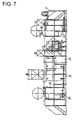
- FIG. 7 is a side view of a resin impregnation facility used to administer the method of the present invention.
- FIG. 8 is a plan view of a resin impregnation facility of Fig. 6.
- FIG. 9A, 9B, and 9C are schematic cross-sectional views that show a resin impregnation operation in the resin impregnation tank in the order of the process steps.
- FIG. 10 is a flowchart that shows a conventional manufacturing method for a stator stack of a resolver.
- the resolver 1 shown in Figures 1 and 2 is used to detect a deviation angle and includes a rotatable, assembled annular rotor stack 20 on the inside of the annular stator stack 10.
- fixed magnetic poles 11b project inwardly and radially from the internal surface of a yoke ring 11a.
- Arc-shaped fixed magnetic teeth 11c are formed on the tips of each fixed magnetic pole 11b in an integral manner.
- a multiplicity of dowels 11d for crimping are formed on the yoke ring 11a and fixed magnetic poles 11b of each yoke layer 11.
- the rotor stack 20 includes a multiplicity of layers formed by press punching thin silicon steel plates in the shape shown in Figure 1. The layers are laminated and fixed by crimping. The rotor stack 20 is formed in an approximate flower petal shape, and a plurality of projections 20a, are formed along the periphery of the stack 20 as shown.
- the manufacturing process of the stator stack 10 is described as follows and includes adding a resin impregnation stage to a corrosion prevention method prior to applying an insulation coating. Further, an anion electro deposition coating is employed (stage 4 of Fig. 6) to provide a coating of insulation instead of the conventional cation electro deposition coating (stage 4 of FIG. 10).
- annular yoke layers 11, as shown in Figure 3 are formed by press punching thin silicon steel plates.
- the yoke layers 11 are laminated, and a number of dowels are crimped to fix the yoke layers 11.
- the stator core 12, as shown in Figure 3 is formed (stage 1 in FIG. 6).
- the stator core 12 is degreased (stage 2), and dried (stage 3), and then the corrosion prevention method of the present invention is performed on the stator core 12.
- FIG. 7 is a side view of the resin impregnation facility and FIG. 8 is a plan view of the resin impregnation facility.
- the parts of the resin impregnation facility are listed from right to left of Figures 6 and 7 as follows: a supply tank 31, a resin impregnation tank 32, an adhered liquid collector 33, a primary washing tank 34, a secondary washing tank 35, and a thermosetting tank 36.
- a highly permeable acrylic resin which is an un-cured liquid thermosetting resin, is contained in the supply tank 31.
- the acrylic resin is maintained at or below a designated temperature (at or below the setting temperature) by being chilled by freezer 37 in FIG. 8, which is installed near the supply tank 31 to prevent the resin from curing.
- the freezer 37 is connected to the resin impregnation tank 32.
- the acrylic resin that is supplied from the supply tank 31 and contained in the resin impregnation tank 32 is also chilled by the freezer 37 so that its temperature is maintained at or below a designated value (at or below the setting temperature) to prevent it from curing.
- the vacuum pump 38 which is installed near the adhered liquid collector 33 and primary washing tank 34, is connected to the resin impregnation tank 32.
- An air compressor which is not shown in the drawings, is connected to the vacuum pump 38 as a pressure source.
- warm water at a designated temperature (a temperature at or above the setting temperature of the acrylic resin) is contained in the thermosetting tank 36.
- the warm water is maintained at the designated temperature by being heated by a sheath heater 39 in FIG. 7.
- FIGS. 9A, 9B and 9C show the resin impregnation operation in the resin impregnation tank 32 in the order of the process steps (dipping, vacuum application, and pressure application).
- stator core 12 that is degreased in process 2 and dried in process 3, as shown in FIG. 6, is vacuum-impregnated with acrylic resin in the resin impregnation facility of FIGS. 7 and 8 (stage A in FIG. 6).
- uncured liquid acrylic resin 40 is contained in the resin impregnation tank 32, and the stator core is dipped in the acrylic resin 40.
- a vacuum is created inside the resin impregnation 32 as shown in FIG. 9B.
- the arrow in Fig. 9B represents the outflow of air.
- air from gaps 16 See Fig. 5
- the highly permeable acrylic resin 40 has sufficiently permeated into the gaps 16 of the stator core 12.
- the gaps 16 in Fig. 5 are exaggerated and simplified for ease of illustration.
- the number of annular yoke plates 11 is not necessarily four, as shown in Fig. 5.
- an air compressor which is not shown in the drawings, is operated to supply compressed air into the resin impregnation tank 32 as shown in FIG. 9C, and the inside of the resin impregnation tank 32 is thus pressurized.
- the arrow in Fig. 9C represents the inflow of air. Then, the acrylic resin thoroughly permeates and fills the gaps 16 of the stator core 12.
- stator core 12 in which acrylic resin is vacuum-impregnated, is brought to the adhered liquid collector 33, which is shown in FIG. 7 and FIG. 8, and the excess acrylic resin adhering to the stator core 12 is removed and collected.
- stator core 12 is rinsed with water, in two stages, with the primary washing tank 34 and secondary washing tank 35 (stage B in FIG. 6).
- the stator core 12 is conveyed to the thermosetting tank 36, and the impregnated acrylic resin is cured (stage C in FIG. 6).
- the rinsed stator core 12 is dipped in warm water, which is contained in the thermosetting tank 36.
- the acrylic resin that has impregnated the gaps 16 of the stator core 12 is cured by heating with to a designated temperature. The cured acrylic resin thoroughly fills the gaps 16 of the stator core 12.
- stator core 12 is removed from the thermosetting tank 36 and dried (stage D in FIG. 6).
- a shot blasting treatment is applied to the stator core 12 (stage E in FIG. 6) to completely remove the excess cured resin that was not removed by the rinsing.
- an insulation coating is applied to the stator core 12 after the corrosion prevention treatment.
- an anion electro deposition coating (stage 4 in FIG. 6) is employed instead of the conventional cation electro deposition coating of FIG. 10.
- the anion electro deposition coating has good edge-covering ability and therefore a sufficient insulation coating can be applied, which increases the corrosion-resistance of the edges of the stator core 12. Therefore, corrosion on these portions is thoroughly prevented.
- a stator stack 10 as shown in Figures 1 and 2 is formed as follows. Insulators 13, as shown in Figures 1 and 2, which include insulation material such as resin, are mounted on opposite sides of the stator core 12 (stage 5 in FIG. 6). Then, windings 14, which include an excitation winding and an output winding and which are schematically represented in Fig 3, are coiled around fixed magnetic poles 11b of the stator core 12 (stage 6 in FIG. 6). Next, the magnetic poles 11b, about which the coils, or windings, are wound, are varnished so that the coiled excitation winding and output winding will not shift due to temperature changes or vibrations (stage 7 in FIG. 6). Then, the coiled magnetic poles 11b are dried (stage 8 in FIG. 6) to complete the process of making the stator stack 10.
- the curing of an acrylic resin that fills the gaps and covers the edges of the stator core 12 provides protection of these areas since the resin is highly corrosion-resistant. This ensures a high corrosion-resistance for the stator core 12 (the stator stack 10). As a result, a saltwater protection case, which has been used during conventional saltwater spraying tests of stator stacks, is no longer required. As a result, the test facility is simpler and less expensive.
- the present invention is described in an embodiment in which a stator stack is employed; however, the present invention can also be applied to the rotor stack of a resolver, and other assorted laminated silicon steel plate parts.
- a corrosion protection method has been described for laminated silicon steel plates that are fixed together to form an integral part.
- the steel lamination is vacuum-impregnated with a highly permeable acrylic resin prior to applying an insulation coating.
- the acrylic resin fills the gaps and covers edges of the steel parts and is cured.
- the method provides saltwater protection for the parts, and consequently, the effects include, for example, a simplification of a saltwater protection test and a decrease in costs.
Landscapes
- Engineering & Computer Science (AREA)
- Power Engineering (AREA)
- Manufacture Of Motors, Generators (AREA)
- Iron Core Of Rotating Electric Machines (AREA)
- Laminated Bodies (AREA)
- Application Of Or Painting With Fluid Materials (AREA)
- Other Surface Treatments For Metallic Materials (AREA)
Abstract
Description
Then,
The yoke layers 11 are laminated, and a number of dowels are crimped to fix the yoke layers 11. Thus, the
An air compressor, which is not shown in the drawings, is connected to the vacuum pump 38 as a pressure source.
In this embodiment of the invention, an anion electro deposition coating (
Claims (17)
- A corrosion prevention method, comprising:stacking steel layers (11) to form a lamination (10);fixing the layers (11) to one another;vacuum impregnating the lamination (10) with an acrylic resin (40), which has a high permeability, to fill gaps (16), which exist between the stacked layers (11), with the acrylic resin (40);curing the acrylic resin (40); andapplying an insulation coating to the lamination (10).
- A corrosion prevention method according to Claim 1, wherein vacuum impregnating the lamination (10) further comprises:dipping the lamination (10) in liquid acrylic resin (40) in a container (32), wherein air is exhausted to create a vacuum within the container (32), andapplying pressure inside the vacuum container (32) to pressurize the container (32).
- A corrosion prevention method according to Claim 1, wherein curing the acrylic resin (40) comprises immersing the lamination (10) in warm water.
- A corrosion prevention method according to Claim 2, wherein curing the acrylic resin (40) further comprises immersing the lamination (10) in warm water.
- A corrosion prevention method according to Claim 1, further comprising applying a shot blasting treatment to the lamination (10) after curing the acrylic resin (40).
- A corrosion prevention method according to Claim 2, further comprising applying a shot blasting treatment to the lamination (10) after curing the acrylic resin (40).
- A corrosion prevention method according to Claim 3, further comprising applying a shot blasting treatment to the lamination (10) after curing the acrylic resin (40).
- A corrosion prevention method according to Claim 1, wherein the application of an insulation coating (15) includes using anion electro deposition.
- A method of producing a stator stack, comprising:press punching a plurality of thin plates to form annular plates (11);laminating and fixing the annular plates (11) to form a stator (12);vacuum-impregnating the stator (12) with resin (40) to fill gaps, which exist between the plates (11), with the resin (40);curing the resin (40) by heating the stator (12) to a predetermined temperature;applying a shot blasting treatment to the stator (12) to remove excess cured resin (40);applying an insulating coating (15) to the stator (12); andmounting insulators (13) on opposite sides of the stator (12).
- A method of producing a stator (12) according to Claim 9, wherein the plates (11) include silicon steel.
- A method of producing a stator stack (10) according to Claim 9, wherein the resin (40) includes an acrylic resin (40).
- A method of producing a stator stack (10) according to Claim 9, wherein the application of the insulating coating (15) further comprises using anion electrodeposition.
- A method of producing a stator (12) according to Claim 9, further comprising:coiling windings (14) around fixed magnetic poles (11b) of the stator (12);varnishing the windings (14) to prevent shifting of the windings (14); anddrying the windings (14).
- A stator (12), comprising:a laminated stack including gaps (16) between layers (11) of the stack, two opposed side surfaces, edges, and fixed magnetic poles (11b);resin impregnating the gaps (16) of the laminated stack (10);an insulator (13) provided on each of opposed side surfaces of the of laminated stack (10); anda plurality of windings (14) coiled around the fixed magnetic poles (11b) of the laminated stack (10).
- A stator (12) according to Claim 14, wherein the laminated stack (10) includes a plurality of steel plates (11).
- A stator (12) according to Claim 14, wherein the resin (40) includes an acrylic resin (40).
- A stator (12) according to Claim 15 further comprising an insulation layer (15) covering the impregnated resin (40).
Applications Claiming Priority (2)
| Application Number | Priority Date | Filing Date | Title |
|---|---|---|---|
| JP2003027424 | 2003-02-04 | ||
| JP2003027424A JP2004238661A (en) | 2003-02-04 | 2003-02-04 | Rust prevention method for component of laminated silicon steel sheet |
Publications (2)
| Publication Number | Publication Date |
|---|---|
| EP1445779A2 true EP1445779A2 (en) | 2004-08-11 |
| EP1445779A3 EP1445779A3 (en) | 2007-05-30 |
Family
ID=32652972
Family Applications (1)
| Application Number | Title | Priority Date | Filing Date |
|---|---|---|---|
| EP20040002360 Withdrawn EP1445779A3 (en) | 2003-02-04 | 2004-02-03 | Corrosion-resistant laminated steel part and corrosion-proofing method for laminated steel parts |
Country Status (3)
| Country | Link |
|---|---|
| US (1) | US20040253465A1 (en) |
| EP (1) | EP1445779A3 (en) |
| JP (1) | JP2004238661A (en) |
Cited By (2)
| Publication number | Priority date | Publication date | Assignee | Title |
|---|---|---|---|---|
| EP1967288A3 (en) * | 2007-03-08 | 2013-03-06 | General Electric Company | Rotor and stator assemblies that utilize magnetic bearings for use in corrosive environments |
| WO2018076915A1 (en) * | 2016-10-31 | 2018-05-03 | 北京金风科创风电设备有限公司 | Vacuum desorption, impregnation and curing system, and vacuum desorption apparatus and process for magnetic pole protection coating |
Families Citing this family (2)
| Publication number | Priority date | Publication date | Assignee | Title |
|---|---|---|---|---|
| US20140239764A1 (en) | 2013-02-27 | 2014-08-28 | Regal Beloit America, Inc. | Laminated rotor with improved magnet adhesion and method of fabricating |
| CN104465061B (en) * | 2013-09-16 | 2016-09-28 | 秀波电子股份有限公司 | Manufacturing method of extremely anisotropic ring magnet and its pressurized alignment mold structure |
Family Cites Families (7)
| Publication number | Priority date | Publication date | Assignee | Title |
|---|---|---|---|---|
| US3183384A (en) * | 1962-09-24 | 1965-05-11 | Jr Robert J Flaherty | Immersible dynamoelectric device |
| US3533867A (en) * | 1967-01-13 | 1970-10-13 | Gen Electric | Methods for reducing electrical losses in and bonding of electrical inductive laminated structures |
| JPS5943512A (en) * | 1982-09-06 | 1984-03-10 | Toshiba Corp | Production of radial iron core |
| US4714623A (en) * | 1985-02-28 | 1987-12-22 | Riccio Louis M | Method and apparatus for applying metal cladding on surfaces and products formed thereby |
| US5935347A (en) * | 1993-12-28 | 1999-08-10 | Alps Electric Co., Ltd. | FE-base soft magnetic alloy and laminated magnetic core by using the same |
| US6462456B1 (en) * | 1998-11-06 | 2002-10-08 | Honeywell International Inc. | Bulk amorphous metal magnetic components for electric motors |
| US6455100B1 (en) * | 1999-04-13 | 2002-09-24 | Elisha Technologies Co Llc | Coating compositions for electronic components and other metal surfaces, and methods for making and using the compositions |
-
2003
- 2003-02-04 JP JP2003027424A patent/JP2004238661A/en active Pending
-
2004
- 2004-01-29 US US10/766,323 patent/US20040253465A1/en not_active Abandoned
- 2004-02-03 EP EP20040002360 patent/EP1445779A3/en not_active Withdrawn
Cited By (2)
| Publication number | Priority date | Publication date | Assignee | Title |
|---|---|---|---|---|
| EP1967288A3 (en) * | 2007-03-08 | 2013-03-06 | General Electric Company | Rotor and stator assemblies that utilize magnetic bearings for use in corrosive environments |
| WO2018076915A1 (en) * | 2016-10-31 | 2018-05-03 | 北京金风科创风电设备有限公司 | Vacuum desorption, impregnation and curing system, and vacuum desorption apparatus and process for magnetic pole protection coating |
Also Published As
| Publication number | Publication date |
|---|---|
| EP1445779A3 (en) | 2007-05-30 |
| US20040253465A1 (en) | 2004-12-16 |
| JP2004238661A (en) | 2004-08-26 |
Similar Documents
| Publication | Publication Date | Title |
|---|---|---|
| TWI724690B (en) | Laminated iron core and rotating electric machine | |
| CA3131659C (en) | Adhesively-laminated core for stator and electric motor | |
| KR102607691B1 (en) | Adhesive laminated cores for stators and rotating electric machines | |
| US3821846A (en) | Method of manufacturing a motor stator assembly | |
| US8716914B2 (en) | Stator of vehicle AC generator and method for manufacturing the same | |
| JP3725776B2 (en) | Method for manufacturing laminated iron core and apparatus for manufacturing the same | |
| KR20210083337A (en) | Adhesive laminated cores for stators and rotating electric machines | |
| CN1312830C (en) | Manufacturing method of a stator of a rotating electric machine | |
| JP7207610B2 (en) | Coating composition for electromagnetic steel sheet, surface-coated electromagnetic steel sheet for bonding, and laminated core | |
| US20190036391A1 (en) | Stator for an electric motor, method for the production thereof, and electric motor | |
| JP2011066987A (en) | Method of manufacturing laminated core, laminated core, and rotary electric machine | |
| EP1364442A2 (en) | Motor with divided stator having bonded laminations | |
| US20040253465A1 (en) | Corrosion-resistant laminated steel part and corrosion-proofing method for laminated steel parts | |
| CN211629958U (en) | stator | |
| CN108347148B (en) | Permanent-magnet slotless DC motor armature and its processing technology | |
| JP6101777B2 (en) | Rotating electric machine stator | |
| JP7816117B2 (en) | Manufacturing method of laminated core | |
| DE102023133261B4 (en) | Manufacturing system and process for the manufacture of a stator and/or a rotor of an electric machine, as well as a computer program product | |
| US12567786B2 (en) | DC motor and interpole coil replacement method | |
| JP7388572B2 (en) | Stator manufacturing method | |
| JP7586631B2 (en) | Rotating electric machine armature and insulation method thereof | |
| Kirkhoff | Processes and design considerations for automatic assembly of electric motor stators | |
| JP2004236464A (en) | Method for fixing slot insulator of rotating electric machine | |
| JP5953389B1 (en) | Stator manufacturing method for rotating electrical machine | |
| JPH0879996A (en) | Core for motor |
Legal Events
| Date | Code | Title | Description |
|---|---|---|---|
| PUAI | Public reference made under article 153(3) epc to a published international application that has entered the european phase |
Free format text: ORIGINAL CODE: 0009012 |
|
| AK | Designated contracting states |
Kind code of ref document: A2 Designated state(s): AT BE BG CH CY CZ DE DK EE ES FI FR GB GR HU IE IT LI LU MC NL PT RO SE SI SK TR |
|
| AX | Request for extension of the european patent |
Extension state: AL LT LV MK |
|
| PUAL | Search report despatched |
Free format text: ORIGINAL CODE: 0009013 |
|
| AK | Designated contracting states |
Kind code of ref document: A3 Designated state(s): AT BE BG CH CY CZ DE DK EE ES FI FR GB GR HU IE IT LI LU MC NL PT RO SE SI SK TR |
|
| AX | Request for extension of the european patent |
Extension state: AL LT LV MK |
|
| AKX | Designation fees paid |
Designated state(s): AT BE BG CH CY CZ DE DK EE ES FI FR GB GR HU IE IT LI LU MC NL PT RO SE SI SK TR |
|
| STAA | Information on the status of an ep patent application or granted ep patent |
Free format text: STATUS: THE APPLICATION IS DEEMED TO BE WITHDRAWN |
|
| 18D | Application deemed to be withdrawn |
Effective date: 20071201 |