EP1445753A2 - Apparatus and method for processing displayed data - Google Patents
Apparatus and method for processing displayed data Download PDFInfo
- Publication number
- EP1445753A2 EP1445753A2 EP04075340A EP04075340A EP1445753A2 EP 1445753 A2 EP1445753 A2 EP 1445753A2 EP 04075340 A EP04075340 A EP 04075340A EP 04075340 A EP04075340 A EP 04075340A EP 1445753 A2 EP1445753 A2 EP 1445753A2
- Authority
- EP
- European Patent Office
- Prior art keywords
- signal
- micom
- image signal
- computer
- memory
- Prior art date
- Legal status (The legal status is an assumption and is not a legal conclusion. Google has not performed a legal analysis and makes no representation as to the accuracy of the status listed.)
- Ceased
Links
Images




Classifications
-
- G—PHYSICS
- G09—EDUCATION; CRYPTOGRAPHY; DISPLAY; ADVERTISING; SEALS
- G09G—ARRANGEMENTS OR CIRCUITS FOR CONTROL OF INDICATING DEVICES USING STATIC MEANS TO PRESENT VARIABLE INFORMATION
- G09G5/00—Control arrangements or circuits for visual indicators common to cathode-ray tube indicators and other visual indicators
- G09G5/003—Details of a display terminal, the details relating to the control arrangement of the display terminal and to the interfaces thereto
-
- G—PHYSICS
- G06—COMPUTING OR CALCULATING; COUNTING
- G06F—ELECTRIC DIGITAL DATA PROCESSING
- G06F3/00—Input arrangements for transferring data to be processed into a form capable of being handled by the computer; Output arrangements for transferring data from processing unit to output unit, e.g. interface arrangements
- G06F3/14—Digital output to display device ; Cooperation and interconnection of the display device with other functional units
-
- G—PHYSICS
- G09—EDUCATION; CRYPTOGRAPHY; DISPLAY; ADVERTISING; SEALS
- G09G—ARRANGEMENTS OR CIRCUITS FOR CONTROL OF INDICATING DEVICES USING STATIC MEANS TO PRESENT VARIABLE INFORMATION
- G09G2360/00—Aspects of the architecture of display systems
- G09G2360/18—Use of a frame buffer in a display terminal, inclusive of the display panel
-
- G—PHYSICS
- G09—EDUCATION; CRYPTOGRAPHY; DISPLAY; ADVERTISING; SEALS
- G09G—ARRANGEMENTS OR CIRCUITS FOR CONTROL OF INDICATING DEVICES USING STATIC MEANS TO PRESENT VARIABLE INFORMATION
- G09G2370/00—Aspects of data communication
- G09G2370/04—Exchange of auxiliary data, i.e. other than image data, between monitor and graphics controller
- G09G2370/045—Exchange of auxiliary data, i.e. other than image data, between monitor and graphics controller using multiple communication channels, e.g. parallel and serial
- G09G2370/047—Exchange of auxiliary data, i.e. other than image data, between monitor and graphics controller using multiple communication channels, e.g. parallel and serial using display data channel standard [DDC] communication
Definitions
- the present invention relates to an apparatus for processing displayed data and method thereof, through which although an image appliance (e.g., PCs) connected to a display device freezes or malfunctions, all unsaved data can be restored without damages.
- an image appliance e.g., PCs
- display devices refer to TV monitors or PC monitors.
- CRT Cathode Ray Tube
- LCD monitors are typical examples thereof.
- Fig. 1 is a schematic block diagram illustrating the structure of a related art CRT monitor connected to a PC.
- the CRT monitor 20 includes a microcomputer (Micom) 22, preamplifier 24, main amplifier 26, and CRT 28.
- input R, G, and B analog image signals from the PC 10 are amplified through the preamplifier 24 and the main amplifier 26, and transmitted to the CRT 28 for display.
- the Micom 22 communicates with the PC through a DDC (Display Data Channel), and controls each component inside of the CRT monitor 20.
- DDC Display Data Channel
- data loss can be very costly, not only in monetary terms but also in downtime especially when the lost data is very important or the user is in a big hurry to prepare the data.
- An object of the invention is to solve at least the above problems and/or disadvantages and to provide at least the advantages described hereinafter.
- one object of the present invention is to solve the foregoing problems by providing an apparatus for processing displayed data and method thereof, through which even if an image applience (e.g., PCs) connected to a display device freezes or malfunctions, all unsaved data can be restored without damages.
- an image applience e.g., PCs
- Another aspect of the invention provides a method for processing displayed data, which includes the steps of: processing and displaying data; determining whether the computer is off or frozen; if the computer is off or frozen, inputting a storage command signal to the display device in order to save displayed data; saving in a memory a storage section of an image signal set for a signal corresponding to the storage command signal and to a synchronizing signal; and when restoring data saved in the memory, converting the data saved in the memory and displaying the converted data.
- the present invention can be advantageously used for minimizing data loss a user has been working on, simply by selecting a data restoration function of the display device to restore all unsaved data.
- the PC malfunction results in data loss
- the user had to reboot the PC and reproduce an image he or she has been previously working on, depending on his or her memory only.
- the present invention resolves this inconvenience.
- Fig. 1 is a schematic block diagram illustrating a structure of a related art CRT (Cathode Ray Tube) monitor connected to a PC;
- CRT Cathode Ray Tube
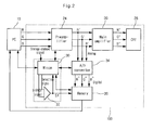
- Fig. 2 is a schematic block diagram illustrating a structure of a CRT (Cathode Ray Tube) monitor having a data restoration function, in accordance with a first preferred embodiment of the present invention
- Fig. 3 shows outputs of a comparator for setting a storage section of image signals to be stored in a memory when a CRT (Cathode Ray Tube) monitor according to the first preferred embodiment of the invention performs restoration of lost data, and illustrates waveforms of the image signals;
- CRT Cathode Ray Tube
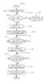
- Fig. 4 is a flow chart describing a procedure of storing image signals when a CRT (Cathode Ray Tube) monitor according to the first preferred embodiment of the invention performs restoration of lost data;
- CRT Cathode Ray Tube
- Fig. 5 is a flow chart describing a procedure of restoring and outputting stored image signals when a CRT (Cathode Ray Tube) monitor according to the first preferred embodiment of the invention performs restoration of lost data;
- CRT Cathode Ray Tube
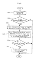
- Fig. 6 is a flow chart describing a method for saving displayed data and recovering lost data
- Fig. 7 is a schematic block diagram illustrating a structure of a LCD monitor having a data restoration function, in accordance with a second preferred embodiment of the present invention.
- Fig. 2 is a schematic block diagram illustrating a structure of a CRT (Cathode Ray Tube) monitor having a data restoration function, in accordance with a first preferred embodiment of the present invention.
- CRT Cathode Ray Tube
- the CRT monitor 100 of the invention further includes a comparator 32, an A/D converter 34, and a memory 36 in addition to the Micom 30, preamplifier 24, main amplifier 26, and CRT 28 which are main components of the related art CRT monitor of Fig. 1.
- the Micom 30 and the comparator 32 can be made as separate components, or the Micom 30 can function as a comparator as well.
- the Micom 30 functions as a comparator, all functions of the comparator (these will be discussed later) are performed at the Micom.
- the user When the PC 10 freezes all of sudden and a user did not save data he or she has been working on, the user inputs a storage command signal through a control panel (not shown) of the monitor. Then the Micom 30 controls the A/D converter 34 to convert input R'G'B' analog image signals from the preamplifier 24 to R ⁇ G ⁇ B ⁇ digital image signals, and controls the memory 36 to save the digital image signals.
- the Micom 30 automatically generates a selection signal and a V-SYNCH (vertical synchronizing) signal, thereby saving image signals currently being worked on in the memory.
- the Micom 30 controls each component inside of the CRT monitor 100. Especially when the user inputs the storage command signal, the Micom 30 responds to the command by outputting a selection signal illustrated in Fig. 3 to the comparator 32.
- the pulse period of the storage command signal is not shorter than the pulse period of the selection signal.
- the comparator 32 compares the selection signal with a V-SYNCH signal from the Micom 30, and outputs the comparison result to the Micom 30 and to the memory 36. On the basis of the comparison result outputted from the comparator 32, the Micom 30 sets a storage section of image signals. More details on the method for setting the storage section of image signals will be provided with reference to Fig. 3.
- the V-SYNCH signal outputted from the Micom is generated when an output H-SYNCH/V-SYNCH signal which is provided from the PC under normal operation is not input to the CRT monitor 100 functioning as a display device, or when a terminal output signal indicating a connection between the PC 10 and the CRT monitor 100 is lost.
- V-FBP Very Fly Back Pulse
- Fig. 3 shows outputs of the comparator for setting the storage section of image signals to be stored in a memory when the CRT monitor according to the first preferred embodiment of the invention performs restoration of lost data, and depicts waveforms of the image signals.
- the comparator 32 receives the selection and V-SYNCH signals from the Micom 30, and compares these two signals with each other. When the logic level of each signal is high or low, the comparator 32 outputs a high level signal.
- the Micom 30 When a first high level signal is outputted from the comparator 32, the Micom 30 outputs a storage start signal (P1), indicating that saving of an image signal has started. When a second high level signal is outputted from the comparator 32, the Micom outputs a storage end signal (P2), indicating that saving of the image signal has ended.
- the Micom 30 After the storage end signal (P2) is outputted, the Micom 30 resets the logic level of the selection signal to a low level. Thus, an interval between the P1 signal and the P2 signal is determined as the storage section (S1) for the image signal to be saved in the memory 36
- the determined storage section (S1) for the image signal equals to a section corresponding to one period of the V-SYNCH signal. More specifically, it is a section for an image signal that corresponds to one frame displayed on the entire monitor screen.
- Fig. 4 is a flow chart describing a procedure of storing image signals when the CRT monitor according to the first preferred embodiment of the invention performs restoration of lost data.
- the storage command signal is input through a control panel (not shown) of the monitor.
- the Micom 30 determines whether the V-SYNCH signal is present (S103).
- the Micom 30 If the V-SYNCH signal is not present ("No" in step 103), an image signal is not going to be displayed on the monitor screen. In this situation, the Micom 30 outputs to the monitor screen a request message for checking a connection state of a signal cable connected to the PC (S105).
- the Micom 30 deletes the data stored previously in the memory 36 to store new digital image(S107), but not all the time.
- the A/D converter 34 receives R'G'B' analog image signals outputted from the preamplifier 24, and converts them to R ⁇ G ⁇ B ⁇ digital image signals (S109). Then the Micom 30 confirms whether the storage start signal (P1) is outputted from the comparator 32 (S111).
- the storage start signal (P1) is outputted at the first point of time when the logic levels of the selection signal and of the V-SYNCH signal being input to the comparator 32 are both high.
- step 111 when the storage start signal (P1) is outputted ("Yes” in step 111), storage of R ⁇ G ⁇ B ⁇ digital image signals in the memory 36 is started (S113). Later, the Micom 30 confirms whether the storage end signal (P2) is outputted from the comparator 32 (S115).
- the storage end signal (P2) is outputted at the second point of time when the logic levels of the selection signal and of the V-SYNCH signal being input to the comparator 32 are both high.
- the Micom 30 When the storage end signal (P2) is outputted ("Yes" in step 115), the Micom 30 resets the selection signal, and ends the digital image signal saving (S117). Then, using a LED (not shown) equipped on the exterior of the monitor or taking advantage of an OSD (On Screen Display) function, the Micom indicates outside that data storage is ended (S119). In this manner, currently displayed image signals can be saved while the data restoration function of the monitor is being performed.
- OSD On Screen Display
- Fig. 5 is a flow chart describing a procedure of restoring and outputting stored image signals when the CRT monitor according to the first preferred embodiment of the invention performs restoration of lost data.
- the Micom transmits to the memory 36 a control signal for commanding output of the pre-stored image signal data (S203).
- the Micom 30 outputs a message to the monitor screen, indicating that there is no data stored (S207) in the memory 36, and ends the procedure.
- the Micom 30 transmits the data of the memory, namely digital image signals, to the PC 10 (S209).
- communication between the memory 36 and the PC 10 can be achieved through a DDC (Display Data Channel) or via a USB (Universal Serial Bus).
- the image signal is retransmitted from the PC 10 (S211).
- the image signal is an analog image signal adequate for outputting to the monitor, having been converted from the digital image signal transmitted to the PC 10 in step 209.
- the Micom 30 receives the retransmitted image signal from the PC 10, and outputs the image signal to the monitor screen (S213). Then, the Micom 30 outputs to the monitor screen a message inquiring the user whether he or she wants to delete the data stored in the memory 36 (S215). If the user inputs a data delete command signal, indicating that he or she wants to delete the pre-stored data ("Yes" in step 215), the Micom 30 deletes all data stored in the memory 36 (S217). In this way, stored image signals can be restored and outputted while the data restoration function of the monitor is being performed.
- the image signals stored in the memory can be outputted to the monitor screen through the A/D converter and the main amplifier.
- Fig. 6 is a flow chart describing a method for saving displayed data and recovering lost data.
- the user applies a storage command signal to the display device, to save the displayed data (S305).
- a storage section of the image signal is created in dependence of a selection signal corresponding to the storage command signal or of a V-SYNCH signal, and saved in the memory (S307).
- the data in the memory is retransmitted to the PC to be converted, or directly displayed without being retransmitted to the PC (S311).
- Fig. 7 is a schematic block diagram illustrating a structure of a LCD monitor having a data restoration function, in accordance with a second preferred embodiment of the present invention.
- the LCD monitor 200 of the invention further includes clock generator 238 and scaler 226, in addition to Micom 230, preamplifier 224, A/D converter 234, comparator 232, LCD panel 228, and memory 236 which are main components of a related art LCD monitor.
- the Micom 230 and the comparator 232 can be made as a separate component, or the Micom 230 can function as a comparator as well.
- the Micom 230 functions as a comparator, all functions of the comparator are performed at the Micom.
- the scaler 226 receives R ⁇ G ⁇ B ⁇ digital image signals outputted from the A/D converter 234, and converts the digital image signals to an adequate format for the LCD panel 228.
- the clock generator 238 provides a standard clock required for processing digital processing to the A/D converter 234 and scaler 226.
- the clock generator 238 is connected to the A/D converter and scaler.
- the clock generator performs signal synchronization in the A/D converter and tuning in the scaler.
- the structure of the CRT monitor 100 (refer to Fig. 2) according to the first embodiment is similar to that of the LCD monitor 200 (refer to Fig. 7) according to the second embodiment, except that the LCD monitor 200 does not include a separate A/D converter because the A/D conversion is already included in the basic data process of the LCD monitor 200 and that the LCD monitor includes the scaler 226 instead of the main amplifier (refer to 26 of Fig. 2), thereby outputting adequate image signals for the LCD panel.
- the operation procedure for data restoration performed in the LCD monitor 200 of the second embodiment is similar to that of the CRT monitor 100 of the first embodiment explained with reference to Fig. 2 to Fig. 6.
- the LCD monitor 200 does not require the A/D converter for converting analog signals to digital signals because it is included in the basic data process.
- the apparatus for processing displayed data and method thereof of the invention enables to restore all unsaved data without damages when the image applience (e.g., PCs) connected to the display device freezes or malfunctions all of sudden.
- image applience e.g., PCs
Landscapes
- Engineering & Computer Science (AREA)
- Theoretical Computer Science (AREA)
- Physics & Mathematics (AREA)
- General Physics & Mathematics (AREA)
- Computer Hardware Design (AREA)
- Human Computer Interaction (AREA)
- General Engineering & Computer Science (AREA)
- Controls And Circuits For Display Device (AREA)
- Control Of Indicators Other Than Cathode Ray Tubes (AREA)
- Facsimiles In General (AREA)
Abstract
Description
- a Micom arranged for controlling a display device and for outputting a selection signal and a vertical synchronizing signal in dependence of the operation of the computer;
- a comparator arranged for comparing the selection signal with the vertical synchronizing signal, each being outputted from the Micom, and outputting a storage related signal;
- a memory for saving an image signal corresponding to the output signal from the comparator; and
- an A/D converter arranged for converting an analog image signal outputted from a preamplifier of the display device to a digital image signal and for transmitting the converted digital image signal to the memory.
Claims (25)
- An apparatus for processing displayed data in a system having a computer for processing data and a display device with an amplifier for amplifying input signals from the computer, the apparatus comprising:a Micom for controlling the display device, and outputting a selection signal and a vertical synchronizing signal in dependence of the operation of the computer;a comparator for comparing the selection signal with the vertical synchronizing signal, each being outputted from the Micom, and outputting a storage related signal; anda memory for saving an image signal corresponding to the storage related signal generated as an output signal from the comparator.
- An apparatus for processing displayed data in a system having a computer for processing data and a display with an amplifier for amplifying input signals from the computer, the apparatus comprising:a Micom for controlling the display, outputting a selection signal and generating a synchronizing signal in dependence of the operation of the computer, and outputting a storage related signal in dependence of the comparison result; andmemory for saving an image signal corresponding to the storage related signal generated as an output signal from the comparator.
- An apparatus according to claim 1, wherein the selection signal is generated in response to a storage command signal externally generated by a user.
- An apparatus according to claim 1, wherein the selection signal is automatically generated by the Micom when malfunction of the computer is detected.
- The apparatus according to claim 1, further comprising:an A/D converter, under the control of the Micom, for converting an analog image signal outputted from a preamplifier of the display device to a digital image signal, and for transmitting the digital image signal to the memory.
- The apparatus according to claim 1, wherein the image signal saved in the memory is a digital image signal outputted from the A/D converter, equipped in the display device, by controlling of the Micom.
- The apparatus according to claim 1, wherein the Micom is arranged to display the image signal saved in the memory to the display device if a restoration command signal is input to the Micom,.
- The apparatus according to claim 1, wherein the comparator is arranged to compare the selection signal with the vertical synchronizing signal, each being outputted from the Micom, and if logic levels of both signals are same, output a storage command signal.
- The apparatus according to claim 1, wherein the Micom is arranged to output a vertical synchronizing signal when an horizontal/vertical synchronisation signal is not input to the display device when the PC is under normal operation, or when a terminal output signal indicates that a connection between the PC and the monitor is under open state.
- The apparatus according to claim 8, wherein the comparator is arranged to compare the selection signal with a vertical fly back pulse signal.
- The apparatus according to claim 8, wherein the comparator is arranged to output the storage related signal when the selection and vertical synchronizing signals outputted from the Micom are both high or low.
- The apparatus according to claim 8, wherein the Micom is arranged to save the image signal in the memory in response to a first command signal outputted from the comparator, and end storage of the image signal in response to a second command signal outputted from the comparator.
- The apparatus according to claim 12, wherein the Micom is arranged to save the image signal in the memory by outputting a storage start signal with respect to the image signal when the first command signal is input from the comparator, , and the Micom is arranged to end storage of the image signal by outputting a storage end signal when the second command signal is input from the comparator,.
- The apparatus according to claim 13, wherein a storage section corresponds to a period of the vertical synchronizing signal, and is a section of an image signal corresponding to one frame displayed on a full monitor screen.
- An apparatus for processing displayed data in a system having a computer for processing data and a display device with an amplifier for amplifying input signals from the computer, the apparatus comprising:a Micom for controlling the display, and outputting a selection signal and a vertical synchronizing signal in dependence of the operation of the computer;a comparator for comparing the selection signal with the synchronizing signal, each being outputted from the Micom, and outputting a storage related signal;a memory for saving an image signal corresponding to the storage related signal generated as an output signal from the comparator;an A/D converter, under the control of the Micom, for converting input analog image signals from the amplifier of the display device to digital image signals; anda scaler for converting an input signals from the A/D converter to a displayable format.
- The apparatus according to claim 15, further comprising:a clock generator, connected to the A/D converter and scaler, for signal synchronization or tuning.
- The apparatus according to claim 15, wherein the Micom and the comparator can be made as separate components, or the Micom performs the function of the a comparator.
- A method for processing displayed data in a system having a computer for processing data and a display device with an amplifier for amplifying input signals from the computer and a controller, the method comprising the steps of:processing and displaying data;determining whether the computer is off or frozen;if the computer is off or frozen, applying a storage command signal to the display device in order to save displayed data; andsaving in a memory a storage section of an image signal set for a signal generated by the storage command signal and a synchronizing signal.
- The method according to claim 18, further comprising the step of:when the data saved in the memory is restored, converting and displaying the data saved in the memory.
- A method for processing displayed data in a system having a computer for processing data and a display device with an amplifier for amplifying input signals from the computer and a controller, the method comprising the steps of:receiving a storage command signal; andin response to a selection signal generated by the storage command signal and a vertical synchronizing signal, said storage command signal being dependent on an operational state of the computer, storing an image signal displayed on the display device in a memory.
- The method according to claim 20, wherein the step of storing the displayed image signal in the memory comprises substeps of:outputting the selection signal;comparing the selection signal with the vertical synchronizing signal, and outputting a storage signal when the two signals are both high or low; andin response to the outputted storage related signal, starting storage of the displayed image signal and/or ending storage of the displayed image signal.
- A method for processing displayed data in a system having a computer for processing data and a display device with an amplifier for amplifying input signals from the computer and a controller, the method comprising the steps of:receiving a storage command signal;in response to a selection signal generated by the storage command signal and a vertical synchronizing signal in dependence of an operational state of the computer, storing an image signal displayed on the display device in a memory;receiving a restoration command signal of data stored in the memory; andreading an image signal stored in the memory, and displaying the image signal on the display device.
- The method according to claim 22, wherein the step of reading the image signal stored in the memory and displaying the image signal on the display device comprises substeps of:in response to the restoration command signal, transmitting the image signal stored in the memory to the computer, amplifier or scaler; anddisplaying the transmitted image signal on a screen of the display device.
- The method according to claim 23, wherein the step of transmitting the image signal stored in the memory to the computer comprises substeps of:converting the received image signal;receiving an image signal retransmitted from the computer; anddisplaying the retransmitted image signal from the computer on the screen of the display device.
- The method according to claim 24, further comprising the steps of:in the computer, receiving the transmitted image signal and converting the image signal to an adequate image signal for transmitting to the display device; andtransmitting the converted image signal to the display device.
Applications Claiming Priority (2)
| Application Number | Priority Date | Filing Date | Title |
|---|---|---|---|
| KR2003006720 | 2003-02-04 | ||
| KR1020030006720A KR20040070559A (en) | 2003-02-04 | 2003-02-04 | An display device having recovery function and method thereof |
Publications (2)
| Publication Number | Publication Date |
|---|---|
| EP1445753A2 true EP1445753A2 (en) | 2004-08-11 |
| EP1445753A3 EP1445753A3 (en) | 2007-02-14 |
Family
ID=32653326
Family Applications (1)
| Application Number | Title | Priority Date | Filing Date |
|---|---|---|---|
| EP04075340A Ceased EP1445753A3 (en) | 2003-02-04 | 2004-02-03 | Apparatus and method for processing displayed data |
Country Status (5)
| Country | Link |
|---|---|
| US (1) | US20040217951A1 (en) |
| EP (1) | EP1445753A3 (en) |
| KR (1) | KR20040070559A (en) |
| CN (1) | CN100416488C (en) |
| TW (1) | TWI297454B (en) |
Cited By (1)
| Publication number | Priority date | Publication date | Assignee | Title |
|---|---|---|---|---|
| DE3927835A1 (en) * | 1989-08-23 | 1991-02-28 | Ritter Starkstromtech | ENCLOSED MEDIUM VOLTAGE SWITCHGEAR |
Families Citing this family (3)
| Publication number | Priority date | Publication date | Assignee | Title |
|---|---|---|---|---|
| TWI284872B (en) * | 2005-11-22 | 2007-08-01 | Chi Mei Optoelectronics Corp | Flat panel display having a data transfer interface with multi-channels and image transfer method thereof |
| US7773099B2 (en) * | 2007-06-28 | 2010-08-10 | Mitsubishi Electric Research Laboratories, Inc. | Context aware image conversion method and playback system |
| KR102600788B1 (en) | 2016-08-01 | 2023-11-13 | 삼성전자주식회사 | Electronic apparatus and method for sensing a accessory |
Family Cites Families (10)
| Publication number | Priority date | Publication date | Assignee | Title |
|---|---|---|---|---|
| CA1031069A (en) * | 1974-11-13 | 1978-05-09 | Shigeru Enomoto | Vertical deflection circuit |
| KR930008445Y1 (en) * | 1989-07-31 | 1993-12-22 | 주식회사 금성사 | Control circuit of stop and operation screen for video phone |
| US5606160A (en) * | 1993-03-25 | 1997-02-25 | Asahi Kogaku Kogyo Kabushiki Kaisha | Symbol reading device |
| KR100196691B1 (en) * | 1996-06-18 | 1999-06-15 | Lg Electronics Inc | Monitor communicated with PC |
| KR100283572B1 (en) * | 1997-02-24 | 2001-03-02 | 윤종용 | How to Display DPMS on Display Device Using OSD |
| KR100258529B1 (en) * | 1997-12-12 | 2000-06-15 | 윤종용 | Screen storage device and method of display monitor |
| JP3817958B2 (en) * | 1999-03-16 | 2006-09-06 | セイコーエプソン株式会社 | PWM control circuit, microcomputer, and electronic device |
| KR100330037B1 (en) * | 2000-07-06 | 2002-03-27 | 구본준, 론 위라하디락사 | Liquid Crystal Display and Driving Method Thereof |
| KR20020057505A (en) * | 2001-01-05 | 2002-07-11 | 구자홍 | Device for reproducting last screen in the monitor |
| KR20020076987A (en) * | 2001-04-21 | 2002-10-11 | 권상세 | Display apparatus and system with the same |
-
2003
- 2003-02-04 KR KR1020030006720A patent/KR20040070559A/en not_active Ceased
-
2004
- 2004-02-03 EP EP04075340A patent/EP1445753A3/en not_active Ceased
- 2004-02-03 US US10/769,815 patent/US20040217951A1/en not_active Abandoned
- 2004-02-04 CN CNB2004100036461A patent/CN100416488C/en not_active Expired - Fee Related
- 2004-02-04 TW TW093102557A patent/TWI297454B/en not_active IP Right Cessation
Cited By (1)
| Publication number | Priority date | Publication date | Assignee | Title |
|---|---|---|---|---|
| DE3927835A1 (en) * | 1989-08-23 | 1991-02-28 | Ritter Starkstromtech | ENCLOSED MEDIUM VOLTAGE SWITCHGEAR |
Also Published As
| Publication number | Publication date |
|---|---|
| TWI297454B (en) | 2008-06-01 |
| CN1519694A (en) | 2004-08-11 |
| TW200500939A (en) | 2005-01-01 |
| EP1445753A3 (en) | 2007-02-14 |
| CN100416488C (en) | 2008-09-03 |
| KR20040070559A (en) | 2004-08-11 |
| US20040217951A1 (en) | 2004-11-04 |
Similar Documents
| Publication | Publication Date | Title |
|---|---|---|
| US6873306B2 (en) | Display controller architecture for portable computers | |
| US5586333A (en) | Method and control apparatus for generating power management signal of computer peripheral equipment in a computer system | |
| US6577322B1 (en) | Method and apparatus for converting video signal resolution | |
| US6646685B1 (en) | Method for controlling on-screen display operation of display apparatus with auxiliary input/output terminal | |
| US8407375B2 (en) | Information processing apparatus and information processing method | |
| KR0175264B1 (en) | Monitor control device and control method of video communication system | |
| EP1881710A1 (en) | Apparatus and method for inspection of electronic devices | |
| GB2331438A (en) | Flat panel display apparatus having on-screen-display function | |
| EP1445753A2 (en) | Apparatus and method for processing displayed data | |
| US7327355B2 (en) | LCD monitor with dual interface and control method thereof | |
| KR20080047811A (en) | Display system including image processing apparatus, Display apparatus and display method connected to image processing apparatus | |
| JP2001092425A (en) | Liquid crystal display | |
| KR100651285B1 (en) | Multi-monitor system with power saving function and control method thereof | |
| JPH10301522A (en) | BNC / D-Sub automatic selection circuit and method | |
| KR100258529B1 (en) | Screen storage device and method of display monitor | |
| JP2009507249A (en) | Display device | |
| JPS6033471Y2 (en) | video hard copy device | |
| JP5198740B2 (en) | Color management system and color management method | |
| KR20030074879A (en) | Equipment and Method for Realizing Frame Function in Monitor | |
| KR200417901Y1 (en) | Dynamic Auto Scanning System | |
| JP2005084391A (en) | Display device | |
| JP2001005430A (en) | Information processing device | |
| KR101200412B1 (en) | Display apparatus | |
| KR20080041788A (en) | Automatic location setting device and method of image display device | |
| KR20020076987A (en) | Display apparatus and system with the same |
Legal Events
| Date | Code | Title | Description |
|---|---|---|---|
| PUAI | Public reference made under article 153(3) epc to a published international application that has entered the european phase |
Free format text: ORIGINAL CODE: 0009012 |
|
| AK | Designated contracting states |
Kind code of ref document: A2 Designated state(s): AT BE BG CH CY CZ DE DK EE ES FI FR GB GR HU IE IT LI LU MC NL PT RO SE SI SK TR |
|
| AX | Request for extension of the european patent |
Extension state: AL LT LV MK |
|
| PUAL | Search report despatched |
Free format text: ORIGINAL CODE: 0009013 |
|
| AK | Designated contracting states |
Kind code of ref document: A3 Designated state(s): AT BE BG CH CY CZ DE DK EE ES FI FR GB GR HU IE IT LI LU MC NL PT RO SE SI SK TR |
|
| AX | Request for extension of the european patent |
Extension state: AL LT LV MK |
|
| RIC1 | Information provided on ipc code assigned before grant |
Ipc: G09G 5/00 20060101ALI20070108BHEP Ipc: G09G 1/16 20060101AFI20040428BHEP |
|
| 17P | Request for examination filed |
Effective date: 20070814 |
|
| 17Q | First examination report despatched |
Effective date: 20070913 |
|
| AKX | Designation fees paid |
Designated state(s): DE FR GB |
|
| STAA | Information on the status of an ep patent application or granted ep patent |
Free format text: STATUS: THE APPLICATION HAS BEEN REFUSED |
|
| 18R | Application refused |
Effective date: 20100505 |