EP1445658A1 - Apparatus and methods for visually identifying the status report of a print job - Google Patents
Apparatus and methods for visually identifying the status report of a print job Download PDFInfo
- Publication number
- EP1445658A1 EP1445658A1 EP03025093A EP03025093A EP1445658A1 EP 1445658 A1 EP1445658 A1 EP 1445658A1 EP 03025093 A EP03025093 A EP 03025093A EP 03025093 A EP03025093 A EP 03025093A EP 1445658 A1 EP1445658 A1 EP 1445658A1
- Authority
- EP
- European Patent Office
- Prior art keywords
- image data
- job
- processing apparatus
- image processing
- terminal apparatus
- Prior art date
- Legal status (The legal status is an assumption and is not a legal conclusion. Google has not performed a legal analysis and makes no representation as to the accuracy of the status listed.)
- Withdrawn
Links
- 238000000034 method Methods 0.000 title claims description 11
- 238000012545 processing Methods 0.000 claims abstract description 24
- 230000002250 progressing effect Effects 0.000 claims description 10
- 238000012546 transfer Methods 0.000 description 18
- 230000006835 compression Effects 0.000 description 5
- 238000007906 compression Methods 0.000 description 5
- 230000003287 optical effect Effects 0.000 description 4
- 238000012937 correction Methods 0.000 description 3
- 230000005540 biological transmission Effects 0.000 description 2
- 230000006870 function Effects 0.000 description 2
- 230000005856 abnormality Effects 0.000 description 1
- 238000003705 background correction Methods 0.000 description 1
- 230000015572 biosynthetic process Effects 0.000 description 1
- 238000004891 communication Methods 0.000 description 1
- 230000000694 effects Effects 0.000 description 1
- 239000000284 extract Substances 0.000 description 1
- 238000001914 filtration Methods 0.000 description 1
- 238000003384 imaging method Methods 0.000 description 1
- 239000004973 liquid crystal related substance Substances 0.000 description 1
- 230000001737 promoting effect Effects 0.000 description 1
- 230000001360 synchronised effect Effects 0.000 description 1
- 238000010792 warming Methods 0.000 description 1
Images





Classifications
-
- H—ELECTRICITY
- H04—ELECTRIC COMMUNICATION TECHNIQUE
- H04N—PICTORIAL COMMUNICATION, e.g. TELEVISION
- H04N1/00—Scanning, transmission or reproduction of documents or the like, e.g. facsimile transmission; Details thereof
- H04N1/32—Circuits or arrangements for control or supervision between transmitter and receiver or between image input and image output device, e.g. between a still-image camera and its memory or between a still-image camera and a printer device
- H04N1/32037—Automation of particular transmitter jobs, e.g. multi-address calling, auto-dialing
- H04N1/32042—Automation of particular transmitter jobs, e.g. multi-address calling, auto-dialing with reading of job-marks on a page
-
- H—ELECTRICITY
- H04—ELECTRIC COMMUNICATION TECHNIQUE
- H04L—TRANSMISSION OF DIGITAL INFORMATION, e.g. TELEGRAPHIC COMMUNICATION
- H04L67/00—Network arrangements or protocols for supporting network services or applications
- H04L67/01—Protocols
- H04L67/02—Protocols based on web technology, e.g. hypertext transfer protocol [HTTP]
-
- H—ELECTRICITY
- H04—ELECTRIC COMMUNICATION TECHNIQUE
- H04L—TRANSMISSION OF DIGITAL INFORMATION, e.g. TELEGRAPHIC COMMUNICATION
- H04L67/00—Network arrangements or protocols for supporting network services or applications
- H04L67/01—Protocols
- H04L67/06—Protocols specially adapted for file transfer, e.g. file transfer protocol [FTP]
-
- H—ELECTRICITY
- H04—ELECTRIC COMMUNICATION TECHNIQUE
- H04L—TRANSMISSION OF DIGITAL INFORMATION, e.g. TELEGRAPHIC COMMUNICATION
- H04L9/00—Cryptographic mechanisms or cryptographic arrangements for secret or secure communications; Network security protocols
- H04L9/40—Network security protocols
-
- H—ELECTRICITY
- H04—ELECTRIC COMMUNICATION TECHNIQUE
- H04L—TRANSMISSION OF DIGITAL INFORMATION, e.g. TELEGRAPHIC COMMUNICATION
- H04L69/00—Network arrangements, protocols or services independent of the application payload and not provided for in the other groups of this subclass
- H04L69/30—Definitions, standards or architectural aspects of layered protocol stacks
- H04L69/32—Architecture of open systems interconnection [OSI] 7-layer type protocol stacks, e.g. the interfaces between the data link level and the physical level
- H04L69/322—Intralayer communication protocols among peer entities or protocol data unit [PDU] definitions
- H04L69/329—Intralayer communication protocols among peer entities or protocol data unit [PDU] definitions in the application layer [OSI layer 7]
Definitions
- the present specification relates to a job progress reporting method and apparatus employed in a network environment, in which a digital copier, a printer, and a terminal apparatus are connected to the network via a LAN, in particular to a job progress reporting method and apparatus capable of visually reporting a job progressing condition from the digital copier to a remote terminal via the network.
- a network infrastructure connecting various components, such as a digital copier, a printer, a scanner, etc., to a network via a LAN rapidly spreads in a business place.
- a plurality of terminal apparatuses e.g. client workstations of personal computers
- each having a network connection function shares these components in increasingly various manners.
- a terminal apparatus issues a printing job request to the printer as a job issuance source, and then receives various reports on a job such as completion, error, ongoing, etc., from the printer.
- a prior art discusses in the Japanese Patent Application Laid Open Number 2001-216105 that a personal computer connected to a network transmits printing data to a printer connected to a network by a device other than an electronic mail.
- the printer then extracts an electronic mail address of the printing job issuance source from the printing data, and then informs prescribed information thereto by the electronic mail.
- Another prior art discusses in the Japanese Patent Application Laid Open number 2000-200226 that a scanner connected to a network reads and transmits image data of an original document to a printer via the network, and the printer copies the image data on a sheet. Further, the prior art enables reporting a copy job status in a scanner or printer to an electronic mail destination previously registered in the scanner.
- a novel image processing apparatus that is connected to a network and operative to perform printing and copying jobs upon a request from a user.
- the image processing apparatus includes a thumbnail image data generating device generating thumbnail image data of image data processed by the job, in particular of at least a first page of the job and/or e.g. of image data representing a picture or figure, an electronic mail transmitting device transmitting an electronic mail having a thumbnail image data of the first page to a mail address of the user when the job is completed or interrupted.
- the electronic mail includes only a URL representing an information source to a mail address assigned to the terminal apparatus when at least one of the jobs is completed or interrupted.
- the mail address is associated with a user code and the image processing apparatus is operable when the user code is inputted and authenticated.
- a digital copier includes a reading unit 50 scanning and reading an original document set on an original document table 2.
- the reading unit 50 includes an optical scanning unit and an exposure platen 7 receiving the original document thereon.
- the optical unit includes an exposure lamp 51, a first mirror 52, a lens 53, and a CCD type image sensor 54 and similar parts. These exposure lamp 51 and first mirror 52 are secured to a fist carriage (not shown). The second and third mirrors 55 and 56 are also secured to a second carriage (not shown). When an original image is read, the first carriage is mechanically moved and scans faster two times than the second carriage so as to maintain a prescribed optical path length.
- the CCD type image sensor 54 simultaneously reads and converts the original image into an electric signal.
- the digital copier includes an automatic original document feeder (ADF) 1 reading a sheet like original document.
- ADF 1 feeds the original document set on the original document table 2 toward an original document reading sensor 6 by means of feeding rollers 3.
- the original document is read by the original document reading sensor 6.
- Image data is obtained and is then receives various image processing operations, such as MTF correction, filtering, compression, etc.
- the image data is stored one after another in an image memory.
- the original document reading sensor 6 may include a contact type full magnification CCD.
- the digital copier also includes a writing unit 57 having a laser output unit 58, an imaging lens 59, and a mirror 60.
- the laser output unit 58 includes a laser diode as a laser light source and a polygon mirror rotated by a motor in a constant high speed. A laser light is irradiated from the writing unit 57 to a photoconductive member 15 included in an image formation system.
- a procedure of printing an image on a PC member 15 is now described.
- a transfer sheet stacked on one of first, second, and third trays 8 to 10 is fed by corresponding one of first, second, and third sheet feeding apparatuses 11, 12, and 13.
- the transfer sheet is then conveyed by a sheet conveyance unit 14 until it contacts the PC member 15.
- a laser light transmitted from the writing unit 57 writes image data stored in the memory on the PC member 15.
- a toner image is then formed when the image data passes through the developing unit 27.
- the transfer sheet receives transfer of the toner image while being conveyed by the conveyance belt 16 in the same speed with the PC member 15.
- the fixing unit 17 fixes the toner image to the transfer sheet.
- a sheet ejection unit 18 then ejects the transfer sheet onto a sheet ejection tray 19.
- the fixing unit 17 is enabled to perform fixing after warming up few seconds by thinning its roller and employing a large power heater therein.
- a transfer sheet fed from one of the sheet feeding trays 8 to 10 and then carrying an image on its one side is conveyed into a duplex sheet entering conveyance route 113 detouring the sheet ejection tray 19 when an inversion route switching pick 115 is switched to a prescribed position shown in Figs. 1 and 2.
- the transfer sheet then switches back at the inversion unit 112, and is conveyed toward a duplex conveyance unit 111 with its left and right sides being aligned by a sheet jogger 117.
- the transfer sheet in the duplex conveyance unit 111 is then conveyed to a vertical conveyance unit 14 and receives printing of an image on the other side, and is then ejected.
- the transfer sheet having switched back at the inversion unit 112 is launched into an inversion sheet ejection route 114 and is ejected.
- a transfer sheet can be ejected onto a finisher 200 from the body.
- the transfer sheets can be temporary stacked onto a staple stack tray 201.
- a stapler unit 202 When all of the desired number of transfer sheets are stored on the staple stack tray 201, such a sheet bundle is stapled by a stapler unit 202, and is ejected either onto an upper or lower election tray 203 or 204.
- the transfer sheet passes through a straight sheet ejection conveyance route 207, and is similarly ejected onto either the ejection tray 203 or 204.
- a transfer sheet conveyed from either a straight sheet ejection conveyance route 207 or the staple stack tray 201 is selectively ejected onto one of those.
- sheet detecting devices 205 and 206 can be employed in the respective sheet ejection trays 203 and 204 so as to detect remaining of a transfer sheet having been printed.
- control unit controlling such a digital copier is now described with reference to Fig. 3.
- the control unit includes a system control section 20 including a main CPU 21.
- the main CPU controls an operation section 30, a liquid crystal display 31, and a key inputting section 32 to input information and output a display.
- the main CPU also controls the ADF 1, the finisher unit 200, and various loads such as a main motor 25, etc to operate.
- an image signal read by the original document reading sensor (e.g. CCD) 6 may be converted into a digital signal by an A/D converter 61.
- the digital signal then receives various processes, such as MTF, Y-corrections, etc., from the respective shading correction section 62 and image processing section 63.
- the image data processed by a magnification processing section 72 is enlarged or reduced in accordance with a magnification ratio, and is then transferred to an image memory controller 65.
- the image data receives primary compression processing in the memory controller 65 and is then written into the image memory 66 to form a bitmap. Operations performed heretofore are continued until the entire pages are written into a memory once original is started to read.
- Bitmap image data (i.e., the image data) of the image memory 66 receives secondary compression from a secondary compression section 67, and is then written into a hard disk HDD 68. Such an operation is preferably not synchronized with reading and writing of the image data from the original document into the image memory 66.
- the bitmap image can be transferred to the HDD 68 at an optional time.
- Thumbnail image data is simultaneously generated in a multipurpose image format such as "jpeg", "tiff", etc., per a page of the image data written in the image memory 66, or only for a leading page, and is then stored in the HDD 68.
- Such thumbnail image data is obtained, for example, by thinning each pixel data mapped (aligned) to an image, in both main and sub scanning (horizontal or vertical) directions on a page.
- the image data written in the image memory 66 is printed, the image data is transferred from the image memory 66 to the memory controller 65. The image data is then transmitted to the writing unit 57 via the writing Y correction unit 71. The image data transferred to the writing unit 57 then forms a latent image on the PC member 15 and is developed, thereby a copy image is obtained. When the image is not printed (i.e., it is simply stored in the HDD 68), such a printing operation is omitted.
- the system control section 20 includes a ROM 69, a RAM 70, and a network interface controller (NIC) 73 beside the main CPU 21.
- the main CPU 21 analyzes printing details written in a page description language (PDL) and converts those into bit map image data when a printing request is received via the network and NIC 73. Further, the main CPU 21 writes the bit map image data in the image memory 66 and stores the same in the HDD 68 after applying secondary compression thereto. Similar to when copying, the main CPU 21 stores thumbnail image data in the HDD 68 in the "tiff" format or another format as bit map image data.
- the NIC 73 includes an electronic mail protocol (i.e., a communication procedure).
- the NIC 73 includes a function of a web page server (i.e., information of each page is linked in a network).
- a web page server i.e., information of each page is linked in a network.
- thumbnail image generating device claimed in claim 1 can be realized in this embodiment by the main CPU 21, and a transmitting device can be realized by the NIC 73.
- a copy operation is started, messages promoting a user to input a user code (e.g. a numerical number) are displayed on a screen of the LCD 31 as shown in Fig. 6 (in step S1).
- the main CPU 21 compares it with a user code listed on a user code table (see Fig. 9) previously registered in the HDD 68 and read in the RAM 70 (in step S2).
- the user code serves as an authentication number restricting users. A copy only becomes available when such a number exists on the user code table.
- step S2 If the input user code does not exist on the user code table (No, in step S2), the screen of Fig. 6 is displayed again so as to promote the user to input the user code again (in step S3).
- the CPU 21 displays a screen allowing the user to designate and request transmission of a job progressing condition report mail (see Fig. 7). Then, if the user selects an indication "Yes” or "NO", information representing selection result is stored and a copy ready screen is simultaneously displayed as shown in Fig. 8. Then, a prescribed copy job is set and starts (in step S4).
- an electronic mail is transmitted to a mail address corresponding to the user code previously input together with a thumbnail image as shown in Fig. 10 (in step S6).
- a code "11112222” is input for the user code, and the electronic mail is transmitted to the corresponding address motoki@copy.icoh.co.jp.
- a reception user code, a job progressing condition information (e.g. "completion"), a reception time, a number of original documents, and a URL of a digital copier and so on are included in the electronic mail.
- a thumbnail image of a first page of a job is also attached thereto.
- a printing job request is similarly transmitted to a digital copier from a terminal apparatus together with a user code (and/or a mail address).
- an electronic mail can be transmitted to a terminal apparatus having a designated mail address, describing job progressing condition information such as completion, interruption, etc., together with a URL of the digital copier without a thumbnail image data.
- the terminal apparatus can then access an information source defined by the URL by giving instruction through a displayed browser, and obtain and display a thumbnail image data of a first page of the job from the information source.
Landscapes
- Engineering & Computer Science (AREA)
- Signal Processing (AREA)
- Computer Networks & Wireless Communication (AREA)
- Computer Security & Cryptography (AREA)
- Automation & Control Theory (AREA)
- Multimedia (AREA)
- Facsimiles In General (AREA)
- Information Transfer Between Computers (AREA)
- Accessory Devices And Overall Control Thereof (AREA)
Abstract
An image processing apparatus is connected to a network via a LAN
(local area network) and operative to perform printing and copying jobs
upon request from a user. The image processing apparatus includes a
thumbnail image data generating device generating thumbnail image
data of a first page of the job. An electronic mail transmitting
device is included in the image processing apparatus to transmit
an electronic mail having a thumbnail image data of the first page
to a mail address of the user when the job is completed or
interrupted in the digital copier.
Description
- The present specification relates to a job progress reporting method and apparatus employed in a network environment, in which a digital copier, a printer, and a terminal apparatus are connected to the network via a LAN, in particular to a job progress reporting method and apparatus capable of visually reporting a job progressing condition from the digital copier to a remote terminal via the network. Background
- A network infrastructure connecting various components, such as a digital copier, a printer, a scanner, etc., to a network via a LAN rapidly spreads in a business place. In such an environment, a plurality of terminal apparatuses (e.g. client workstations of personal computers) each having a network connection function shares these components in increasingly various manners. For example, when a printer is utilized through the network in such a conventional sharing manner, a terminal apparatus issues a printing job request to the printer as a job issuance source, and then receives various reports on a job such as completion, error, ongoing, etc., from the printer.
- A prior art discusses in the Japanese Patent Application Laid Open Number 2001-216105 that a personal computer connected to a network transmits printing data to a printer connected to a network by a device other than an electronic mail. The printer then extracts an electronic mail address of the printing job issuance source from the printing data, and then informs prescribed information thereto by the electronic mail.
- Another prior art discusses in the Japanese Patent Application Laid Open number 2000-200226 that a scanner connected to a network reads and transmits image data of an original document to a printer via the network, and the printer copies the image data on a sheet. Further, the prior art enables reporting a copy job status in a scanner or printer to an electronic mail destination previously registered in the scanner.
- However, assuming that a remote terminal apparatus can receive such reports as in the above-mentioned patent publications, an operator operating the terminal apparatus hardly identify such a job from the reports.
- A novel image processing apparatus that is connected to a network and operative to perform printing and copying jobs upon a request from a user. The image processing apparatus includes a thumbnail image data generating device generating thumbnail image data of image data processed by the job, in particular of at least a first page of the job and/or e.g. of image data representing a picture or figure, an electronic mail transmitting device transmitting an electronic mail having a thumbnail image data of the first page to a mail address of the user when the job is completed or interrupted.
- In another embodiment, the electronic mail includes only a URL representing an information source to a mail address assigned to the terminal apparatus when at least one of the jobs is completed or interrupted.
- In yet another embodiment, the mail address is associated with a user code and the image processing apparatus is operable when the user code is inputted and authenticated.
- A more complete appreciation of the present invention and many of the attendant advantages thereof will be readily obtained as the same becomes better understood by reference to the following detailed description when considered in connection with the accompanying drawings, wherein:
- Fig. 1 illustrates a digital copier connected to a network according to a preferred embodiment;
- Fig. 2 illustrates a sheet conveyance path included in the digital copier;
- Fig. 3 illustrates a control unit also included in the digital copier;
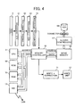
- Fig. 4 illustrates a system control section and an image processing section included in the digital copier;
- Fig. 5 illustrates an operational flow used when a copy job progressing condition is reported from the digital copier to a remote terminal through the network;
- Fig. 6 illustrates an input screen provided in the digital copier for allowing a user to input a job;
- Fig. 7 also illustrates a screen provided in the digital copier for allowing a user to input a job reporting request;
- Fig. 8 illustrates a screen appearing when the digital copier is ready to copy;
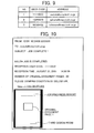
- Fig. 9 illustrates a correspondence between a user and a mail address;
- Fig. 10 illustrates an exemplary screen displaying the job progressing report together with a thumbnail; and
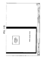
- Fig. 11 also illustrates an exemplary screen displaying the job progressing report together with a URL of a thumbnail source.
-
- Referring now to the drawings, wherein like reference numerals designate identical or corresponding parts throughout the several views, and in particular in Fig. 1, a digital copier includes a
reading unit 50 scanning and reading an original document set on an original document table 2. Thereading unit 50 includes an optical scanning unit and anexposure platen 7 receiving the original document thereon. The optical unit includes anexposure lamp 51, afirst mirror 52, alens 53, and a CCDtype image sensor 54 and similar parts. Theseexposure lamp 51 andfirst mirror 52 are secured to a fist carriage (not shown). The second andthird mirrors 55 and 56 are also secured to a second carriage (not shown). When an original image is read, the first carriage is mechanically moved and scans faster two times than the second carriage so as to maintain a prescribed optical path length. Such an optical scanner is driven by a scanner driving motor (not shown). The CCDtype image sensor 54 simultaneously reads and converts the original image into an electric signal. The digital copier includes an automatic original document feeder (ADF) 1 reading a sheet like original document. The ADF 1 feeds the original document set on the original document table 2 toward an originaldocument reading sensor 6 by means offeeding rollers 3. When passing through the originaldocument reading sensor 6 in a constant speed, the original document is read by the originaldocument reading sensor 6. Image data is obtained and is then receives various image processing operations, such as MTF correction, filtering, compression, etc. The image data is stored one after another in an image memory. The originaldocument reading sensor 6 may include a contact type full magnification CCD. As shown, the digital copier also includes awriting unit 57 having alaser output unit 58, animaging lens 59, and amirror 60. Thelaser output unit 58 includes a laser diode as a laser light source and a polygon mirror rotated by a motor in a constant high speed. A laser light is irradiated from thewriting unit 57 to aphotoconductive member 15 included in an image formation system. - A procedure of printing an image on a
PC member 15 is now described. First, a transfer sheet stacked on one of first, second, andthird trays 8 to 10 is fed by corresponding one of first, second, and thirdsheet feeding apparatuses sheet conveyance unit 14 until it contacts thePC member 15. A laser light transmitted from thewriting unit 57 writes image data stored in the memory on thePC member 15. A toner image is then formed when the image data passes through the developingunit 27. The transfer sheet receives transfer of the toner image while being conveyed by theconveyance belt 16 in the same speed with thePC member 15. Subsequently, thefixing unit 17 fixes the toner image to the transfer sheet. Asheet ejection unit 18 then ejects the transfer sheet onto asheet ejection tray 19. Thefixing unit 17 is enabled to perform fixing after warming up few seconds by thinning its roller and employing a large power heater therein. When a duplex copy is formed on a transfer sheet, a transfer sheet fed from one of thesheet feeding trays 8 to 10 and then carrying an image on its one side is conveyed into a duplex sheet enteringconveyance route 113 detouring thesheet ejection tray 19 when an inversionroute switching pick 115 is switched to a prescribed position shown in Figs. 1 and 2. The transfer sheet then switches back at theinversion unit 112, and is conveyed toward aduplex conveyance unit 111 with its left and right sides being aligned by asheet jogger 117. The transfer sheet in theduplex conveyance unit 111 is then conveyed to avertical conveyance unit 14 and receives printing of an image on the other side, and is then ejected. Further, when the transfer sheet is simply inverted and ejected from a body, the transfer sheet having switched back at theinversion unit 112 is launched into an inversionsheet ejection route 114 and is ejected. Further, a transfer sheet can be ejected onto afinisher 200 from the body. In order to staple thefinisher 200, the transfer sheets can be temporary stacked onto astaple stack tray 201. When all of the desired number of transfer sheets are stored on thestaple stack tray 201, such a sheet bundle is stapled by astapler unit 202, and is ejected either onto an upper orlower election tray ejection conveyance route 207, and is similarly ejected onto either the ejection tray 203 or 204. If theejection trays ejection conveyance route 207 or thestaple stack tray 201 is selectively ejected onto one of those. Further,sheet detecting devices sheet ejection trays - A control unit controlling such a digital copier is now described with reference to Fig. 3. As shown, the control unit includes a
system control section 20 including amain CPU 21. The main CPU controls anoperation section 30, aliquid crystal display 31, and akey inputting section 32 to input information and output a display. The main CPU also controls theADF 1, thefinisher unit 200, and various loads such as amain motor 25, etc to operate. - A
system control section 20 and an image processing section are now described with reference to Fig. 4. As shown, an image signal read by the original document reading sensor (e.g. CCD) 6 may be converted into a digital signal by an A/D converter 61. The digital signal then receives various processes, such as MTF, Y-corrections, etc., from the respectiveshading correction section 62 andimage processing section 63. The image data processed by amagnification processing section 72 is enlarged or reduced in accordance with a magnification ratio, and is then transferred to animage memory controller 65. The image data receives primary compression processing in thememory controller 65 and is then written into theimage memory 66 to form a bitmap. Operations performed heretofore are continued until the entire pages are written into a memory once original is started to read.
Bitmap image data (i.e., the image data) of theimage memory 66 receives secondary compression from asecondary compression section 67, and is then written into ahard disk HDD 68. Such an operation is preferably not synchronized with reading and writing of the image data from the original document into theimage memory 66. - Specifically, when the image data is stored in the
image memory 66 and the HDD is standby state, the bitmap image can be transferred to theHDD 68 at an optional time. Thumbnail image data is simultaneously generated in a multipurpose image format such as "jpeg", "tiff", etc., per a page of the image data written in theimage memory 66, or only for a leading page, and is then stored in theHDD 68. Such thumbnail image data is obtained, for example, by thinning each pixel data mapped (aligned) to an image, in both main and sub scanning (horizontal or vertical) directions on a page. - Further, when image data written in the
image memory 66 is printed, the image data is transferred from theimage memory 66 to thememory controller 65. The image data is then transmitted to thewriting unit 57 via the writingY correction unit 71. The image data transferred to thewriting unit 57 then forms a latent image on thePC member 15 and is developed, thereby a copy image is obtained. When the image is not printed (i.e., it is simply stored in the HDD 68), such a printing operation is omitted. - Further, the
system control section 20 includes aROM 69, aRAM 70, and a network interface controller (NIC) 73 beside themain CPU 21. Themain CPU 21 analyzes printing details written in a page description language (PDL) and converts those into bit map image data when a printing request is received via the network andNIC 73. Further, themain CPU 21 writes the bit map image data in theimage memory 66 and stores the same in theHDD 68 after applying secondary compression thereto. Similar to when copying, themain CPU 21 stores thumbnail image data in theHDD 68 in the "tiff" format or another format as bit map image data. Further, theNIC 73 includes an electronic mail protocol (i.e., a communication procedure). Thus, both mail address of the digital copier and transmission details can be transmitted to an external network in accordance with the electronic mail protocol. TheNIC 73 includes a function of a web page server (i.e., information of each page is linked in a network). Thus, when a page is requested to display, an HTML file generated for a plurality of pages can be transmitted to a request source together with job progressing in the digital copier, such as job completion, interruption, abnormality, etc. - Thus, a thumbnail image generating device claimed in
claim 1 can be realized in this embodiment by themain CPU 21, and a transmitting device can be realized by theNIC 73. - An operation of a copy job designated through a
key input section 32 of the digital copier and an operational flow executed when progress of the copy job is reported via the network are now described with reference to Fig. 5. When a copy operation is started, messages promoting a user to input a user code (e.g. a numerical number) are displayed on a screen of theLCD 31 as shown in Fig. 6 (in step S1). When the user inputs the user code through thekey input section 32, themain CPU 21 compares it with a user code listed on a user code table (see Fig. 9) previously registered in theHDD 68 and read in the RAM 70 (in step S2). Thus, the user code serves as an authentication number restricting users. A copy only becomes available when such a number exists on the user code table. If the input user code does not exist on the user code table (No, in step S2), the screen of Fig. 6 is displayed again so as to promote the user to input the user code again (in step S3). In contrast, if the input user code exists on the user code table (Yes, in step S2) , theCPU 21 displays a screen allowing the user to designate and request transmission of a job progressing condition report mail (see Fig. 7). Then, if the user selects an indication "Yes" or "NO", information representing selection result is stored and a copy ready screen is simultaneously displayed as shown in Fig. 8. Then, a prescribed copy job is set and starts (in step S4). When the copy job is completed or interrupted (Yes, in step S5), and when "Yes" has been selected in the above, an electronic mail is transmitted to a mail address corresponding to the user code previously input together with a thumbnail image as shown in Fig. 10 (in step S6). For example, when a code "11112222" is input for the user code, and the electronic mail is transmitted to the corresponding address motoki@copy.icoh.co.jp. As shown in Fig. 10, a reception user code, a job progressing condition information (e.g. "completion"), a reception time, a number of original documents, and a URL of a digital copier and so on are included in the electronic mail. A thumbnail image of a first page of a job is also attached thereto. As a result, the user can readily exactly identify a digital copier and a completed or interrupted job when receiving the mail. The above-mentioned operation is explained assuming that a job is copying of the digital copier. However, the similar effect can be obtained when the job is printing. Specifically, a printing job request is similarly transmitted to a digital copier from a terminal apparatus together with a user code (and/or a mail address). - Further, as shown in Fig. 11, when a designated copying or printing job is completed or interrupted by some reason, an electronic mail can be transmitted to a terminal apparatus having a designated mail address, describing job progressing condition information such as completion, interruption, etc., together with a URL of the digital copier without a thumbnail image data. The terminal apparatus can then access an information source defined by the URL by giving instruction through a displayed browser, and obtain and display a thumbnail image data of a first page of the job from the information source.
Claims (5)
- An image processing apparatus (1, 15, 17, 20, 27, 50, 57) connectable to a network and operative to perform printing and/or copying jobs upon a request from a user, said image processing apparatus comprising:a thumbnail image data generating device (65, 66) configured to generate thumbnail image data of image data processed by the job; andan electronic mail transmitting device (73) configured to transmit an electronic mail including the thumbnail image data to a mail address of the user when the job is completed or interrupted.
- A method for reporting, via a network, a job progressing condition in an image processing apparatus performing printing and copying jobs upon a request of a user, said method comprising the steps of:determining if at least one of the jobs is completed or interrupted in the image processing apparatus; andgenerating thumbnail image data of image data processed by the job;transmitting an electronic mail having the thumbnail image data to a mail address of the user when at least one of the jobs is completed or interrupted.
- A method for reporting a job progressing condition in an image processing apparatus to a terminal apparatus requesting thereto a job via a network, said method comprising the steps of:determining if at least one of jobs is completed or interrupted in the image processing apparatus;generating thumbnail image data of image data processed by the job, said thumbnail image data is stored in an information source provided in the image processing apparatus;transmitting an electronic mail having a URL representing the information source to a mail address assigned to the terminal apparatus when at least one of the jobs is completed or interrupted;allowing the terminal apparatus having the mail address to access the information source via a browser displayed on the terminal apparatus; andallowing the terminal apparatus to obtain the thumbnail image data.
- A system comprising an image processing apparatus and a terminal apparatus linked via a network, said image processing apparatus comprising:determining means for determining if at least one of jobs is completed or interrupted in the image processing apparatus;generating means for generating thumbnail image data of image data processed by the job, said thumbnail image data is stored in an information source provided in the image processing apparatus; andtransmitting means for transmitting an electronic mail having a URL representing the information source to a mail address assigned to the terminal apparatus when at least on of the jobs is completed or interrupted;the terminal apparatus comprising:accessing means for allowing the terminal apparatus having the mail address to access the information source via a browser displayed on the terminal apparatus; andobtaining means for allowing the terminal apparatus to obtain the thumbnail image data.
- The apparatus of claim 1, the method of claim 2 or 3, or the system of claim 4, wherein said mail address is associated with a user code representing a user, wherein said image processing apparatus is operable when the user code is input and authenticated.
Applications Claiming Priority (2)
| Application Number | Priority Date | Filing Date | Title |
|---|---|---|---|
| JP2002320052 | 2002-11-01 | ||
| JP2002320052A JP2004157595A (en) | 2002-11-01 | 2002-11-01 | Image processing apparatus and job result notification method thereof |
Publications (1)
| Publication Number | Publication Date |
|---|---|
| EP1445658A1 true EP1445658A1 (en) | 2004-08-11 |
Family
ID=32652541
Family Applications (1)
| Application Number | Title | Priority Date | Filing Date |
|---|---|---|---|
| EP03025093A Withdrawn EP1445658A1 (en) | 2002-11-01 | 2003-11-03 | Apparatus and methods for visually identifying the status report of a print job |
Country Status (3)
| Country | Link |
|---|---|
| US (1) | US20040139164A1 (en) |
| EP (1) | EP1445658A1 (en) |
| JP (1) | JP2004157595A (en) |
Families Citing this family (12)
| Publication number | Priority date | Publication date | Assignee | Title |
|---|---|---|---|---|
| JP4102794B2 (en) | 2003-09-19 | 2008-06-18 | 株式会社リコー | Image forming apparatus, image processing apparatus, image forming method, and program causing computer to execute the method |
| JP2005161677A (en) * | 2003-12-02 | 2005-06-23 | Ricoh Co Ltd | Image forming apparatus, control method, control program, and recording medium in image forming apparatus |
| US7920281B2 (en) * | 2004-06-21 | 2011-04-05 | Sharp Laboratories Of America, Inc. | Imaging job monitoring with reduced content image |
| JP2006053784A (en) * | 2004-08-12 | 2006-02-23 | Fuji Xerox Co Ltd | Print processor, print processing method, image output device, print processing method of print processor and image output device, print processing system, and print processing program |
| JP4387285B2 (en) * | 2004-11-01 | 2009-12-16 | シャープ株式会社 | Printing apparatus, printing control method, printing control program, and recording medium for recording printing control program |
| JP4618796B2 (en) * | 2005-08-31 | 2011-01-26 | 株式会社リコー | Received document input / output device |
| JP2008049509A (en) * | 2006-08-23 | 2008-03-06 | Kyocera Mita Corp | Image forming apparatus |
| JP4323512B2 (en) * | 2006-12-18 | 2009-09-02 | シャープ株式会社 | Image processing apparatus and image processing system |
| JP2008312133A (en) * | 2007-06-18 | 2008-12-25 | Ricoh Co Ltd | Image data generation apparatus, image data generation method, and image data generation program |
| US20090089386A1 (en) * | 2007-09-28 | 2009-04-02 | Samsung Techwin Co., Ltd. | Method of communicating e-mail and apparatus using the same |
| JP5371549B2 (en) * | 2009-05-28 | 2013-12-18 | キヤノン株式会社 | Print control apparatus, print control method, and computer program |
| JP7271345B2 (en) | 2019-07-08 | 2023-05-11 | キヤノン株式会社 | IMAGE PROCESSING DEVICE, CONTROL METHOD FOR IMAGE PROCESSING DEVICE, AND PROGRAM |
Citations (5)
| Publication number | Priority date | Publication date | Assignee | Title |
|---|---|---|---|---|
| JP2001024822A (en) * | 1999-07-09 | 2001-01-26 | Matsushita Electric Ind Co Ltd | Image reading device |
| JP2001075892A (en) * | 1999-09-09 | 2001-03-23 | Matsushita Electric Ind Co Ltd | E-mail receiving device, e-mail receiving method, and recording medium |
| US20020054397A1 (en) * | 2000-11-06 | 2002-05-09 | Hiroyuki Matsushima | Method of and device for image processing, image forming device, and computer product |
| US20020063877A1 (en) * | 1997-06-04 | 2002-05-30 | Jeanne M. Lucivero | Print driver system having a user interface and a method for processing raster data |
| US20020133543A1 (en) * | 2001-03-14 | 2002-09-19 | Yoko Fujiwara | Device, method, and program for data transmission as well as computer readable recording medium stored with program |
Family Cites Families (20)
| Publication number | Priority date | Publication date | Assignee | Title |
|---|---|---|---|---|
| DE3618728A1 (en) * | 1985-06-04 | 1986-12-04 | Ricoh Co., Ltd., Tokio/Tokyo | CONTROL DEVICE FOR PAPER FEEDING IN A COPIER |
| US5131079A (en) * | 1988-03-28 | 1992-07-14 | Ricoh Company, Ltd. | Method of controlling a display and a display control device for a copying machine |
| JP2685845B2 (en) * | 1988-11-09 | 1997-12-03 | 株式会社リコー | Copier control device |
| JP2823253B2 (en) * | 1989-07-24 | 1998-11-11 | 株式会社リコー | Double-sided paper feed controller for copier |
| JPH0363670A (en) * | 1989-08-01 | 1991-03-19 | Ricoh Co Ltd | Controller for copying machine |
| JP2536713Y2 (en) * | 1989-11-29 | 1997-05-28 | 株式会社リコー | Electrophotographic equipment |
| US5228669A (en) * | 1990-09-21 | 1993-07-20 | Ricoh Company, Ltd. | Automatic document feeder for an image forming apparatus |
| JPH05292282A (en) * | 1992-04-08 | 1993-11-05 | Minolta Camera Co Ltd | Recorder for received picture |
| JP3660363B2 (en) * | 1992-05-28 | 2005-06-15 | 株式会社リコー | Image forming apparatus management system and image forming apparatus |
| JP3532048B2 (en) * | 1996-03-27 | 2004-05-31 | 株式会社リコー | Digital copier |
| JPH104467A (en) * | 1996-04-18 | 1998-01-06 | Ricoh Co Ltd | Image forming device |
| JP3307855B2 (en) * | 1997-06-30 | 2002-07-24 | 松下電送システム株式会社 | Facsimile-type e-mail device, information terminal device, and method for transferring e-mail data of facsimile-type e-mail device |
| US6825955B1 (en) * | 1997-12-01 | 2004-11-30 | Ricoh Company, Ltd. | Method and apparatus for facsimile that notifies an e-mail transmission using facsimile protocol |
| US6932523B1 (en) * | 1999-08-31 | 2005-08-23 | Brother Kogyo Kabushiki Kaisha | Printing system including a printer and client devices connected by a network |
| US6622266B1 (en) * | 2000-06-09 | 2003-09-16 | International Business Machines Corporation | Method for specifying printer alert processing |
| US20040021895A1 (en) * | 2002-08-01 | 2004-02-05 | Lay Daniel Travis | Systems and methods for reviewing printed hardcopy |
| US6977744B2 (en) * | 2001-05-11 | 2005-12-20 | General Electric Company | Web based client side batch printing |
| US6975419B2 (en) * | 2001-06-18 | 2005-12-13 | Hewlett-Packard Development Company, L.P. | System and method for mobile printing |
| EP1306746B1 (en) * | 2001-10-25 | 2007-09-05 | Hewlett-Packard Company | Remote network printing |
| US7031009B2 (en) * | 2001-12-26 | 2006-04-18 | Xerox Corporation | Use of e-mail for capture of document metadata |
-
2002
- 2002-11-01 JP JP2002320052A patent/JP2004157595A/en active Pending
-
2003
- 2003-10-27 US US10/692,745 patent/US20040139164A1/en not_active Abandoned
- 2003-11-03 EP EP03025093A patent/EP1445658A1/en not_active Withdrawn
Patent Citations (5)
| Publication number | Priority date | Publication date | Assignee | Title |
|---|---|---|---|---|
| US20020063877A1 (en) * | 1997-06-04 | 2002-05-30 | Jeanne M. Lucivero | Print driver system having a user interface and a method for processing raster data |
| JP2001024822A (en) * | 1999-07-09 | 2001-01-26 | Matsushita Electric Ind Co Ltd | Image reading device |
| JP2001075892A (en) * | 1999-09-09 | 2001-03-23 | Matsushita Electric Ind Co Ltd | E-mail receiving device, e-mail receiving method, and recording medium |
| US20020054397A1 (en) * | 2000-11-06 | 2002-05-09 | Hiroyuki Matsushima | Method of and device for image processing, image forming device, and computer product |
| US20020133543A1 (en) * | 2001-03-14 | 2002-09-19 | Yoko Fujiwara | Device, method, and program for data transmission as well as computer readable recording medium stored with program |
Non-Patent Citations (2)
| Title |
|---|
| PATENT ABSTRACTS OF JAPAN vol. 2000, no. 16 8 May 2001 (2001-05-08) * |
| PATENT ABSTRACTS OF JAPAN vol. 2000, no. 20 10 July 2001 (2001-07-10) * |
Also Published As
| Publication number | Publication date |
|---|---|
| JP2004157595A (en) | 2004-06-03 |
| US20040139164A1 (en) | 2004-07-15 |
Similar Documents
| Publication | Publication Date | Title |
|---|---|---|
| CN101473640B (en) | Image processing apparatus and control method thereof and image processing system | |
| KR20010093770A (en) | Control method for image processing apparatus connectable to computer network | |
| US7904811B2 (en) | Text/image storage device, image reading device, and image forming apparatus | |
| US20090031231A1 (en) | Information processing apparatus, information processing method, and storage medium | |
| EP1445658A1 (en) | Apparatus and methods for visually identifying the status report of a print job | |
| JP6376744B2 (en) | Image reading apparatus, method for controlling image reading apparatus, program, and storage medium | |
| JP4489129B2 (en) | Remote USB device usage system | |
| EP1753219A1 (en) | Image processing apparatus, image output method, and computer program product | |
| US20120026543A1 (en) | Image processing apparatus | |
| JP2006333352A (en) | Image forming apparatus | |
| JP3538325B2 (en) | Network system for image forming device | |
| JP2000347826A (en) | Image forming apparatus network system and connection operation method thereof | |
| JP2010114749A (en) | Image forming apparatus | |
| JP2002142050A (en) | Image forming system | |
| JP4437739B2 (en) | Image forming apparatus and program | |
| JPH1188570A (en) | Image forming device | |
| JP2004064452A (en) | Image processing apparatus and image processing job interruption notification method | |
| JP4113818B2 (en) | Image forming connection system | |
| JP2005197961A (en) | Image forming connection system | |
| JP2007049252A (en) | Image processing apparatus, image output method, program, and recording medium | |
| JP2005079678A (en) | Image forming connection system | |
| JP4053317B2 (en) | Image processing system | |
| JPH10322533A (en) | Copier and copier network system | |
| JP2005348348A (en) | Image forming system and image forming apparatus control method | |
| JP2006301812A (en) | Printing system and printing processing method |
Legal Events
| Date | Code | Title | Description |
|---|---|---|---|
| PUAI | Public reference made under article 153(3) epc to a published international application that has entered the european phase |
Free format text: ORIGINAL CODE: 0009012 |
|
| AK | Designated contracting states |
Kind code of ref document: A1 Designated state(s): AT BE BG CH CY CZ DE DK EE ES FI FR GB GR HU IE IT LI LU MC NL PT RO SE SI SK TR |
|
| AX | Request for extension of the european patent |
Extension state: AL LT LV MK |
|
| 17P | Request for examination filed |
Effective date: 20040908 |
|
| AKX | Designation fees paid |
Designated state(s): DE ES FR GB IT NL |
|
| 17Q | First examination report despatched |
Effective date: 20071121 |
|
| STAA | Information on the status of an ep patent application or granted ep patent |
Free format text: STATUS: THE APPLICATION HAS BEEN WITHDRAWN |
|
| 18W | Application withdrawn |
Effective date: 20090525 |