EP1445533B1 - Lighting or signalling device for motor vehicle with built-in complementary module - Google Patents
Lighting or signalling device for motor vehicle with built-in complementary module Download PDFInfo
- Publication number
- EP1445533B1 EP1445533B1 EP04290248.6A EP04290248A EP1445533B1 EP 1445533 B1 EP1445533 B1 EP 1445533B1 EP 04290248 A EP04290248 A EP 04290248A EP 1445533 B1 EP1445533 B1 EP 1445533B1
- Authority
- EP
- European Patent Office
- Prior art keywords
- complementary module
- module
- lighting element
- lighting
- counterpart
- Prior art date
- Legal status (The legal status is an assumption and is not a legal conclusion. Google has not performed a legal analysis and makes no representation as to the accuracy of the status listed.)
- Expired - Lifetime
Links
- 230000000295 complement effect Effects 0.000 title claims description 66
- 230000011664 signaling Effects 0.000 title claims description 4
- 238000007789 sealing Methods 0.000 claims description 18
- 229910052724 xenon Inorganic materials 0.000 claims description 5
- FHNFHKCVQCLJFQ-UHFFFAOYSA-N xenon atom Chemical compound [Xe] FHNFHKCVQCLJFQ-UHFFFAOYSA-N 0.000 claims description 5
- 230000005540 biological transmission Effects 0.000 description 3
- 238000000034 method Methods 0.000 description 3
- 230000008520 organization Effects 0.000 description 3
- 230000000903 blocking effect Effects 0.000 description 2
- 230000006835 compression Effects 0.000 description 2
- 238000007906 compression Methods 0.000 description 2
- 238000010891 electric arc Methods 0.000 description 2
- 238000004519 manufacturing process Methods 0.000 description 2
- 239000012528 membrane Substances 0.000 description 2
- 241001080024 Telles Species 0.000 description 1
- 230000005494 condensation Effects 0.000 description 1
- 238000009833 condensation Methods 0.000 description 1
- 230000007423 decrease Effects 0.000 description 1
- 230000002950 deficient Effects 0.000 description 1
- 230000009977 dual effect Effects 0.000 description 1
- 235000021183 entrée Nutrition 0.000 description 1
- 230000008595 infiltration Effects 0.000 description 1
- 238000001764 infiltration Methods 0.000 description 1
- 238000003780 insertion Methods 0.000 description 1
- 230000037431 insertion Effects 0.000 description 1
- 230000010354 integration Effects 0.000 description 1
- 239000007788 liquid Substances 0.000 description 1
- 239000002184 metal Substances 0.000 description 1
- 230000000717 retained effect Effects 0.000 description 1
- 230000002441 reversible effect Effects 0.000 description 1
- 238000010079 rubber tapping Methods 0.000 description 1
- 230000008054 signal transmission Effects 0.000 description 1
- 239000013589 supplement Substances 0.000 description 1
- XLYOFNOQVPJJNP-UHFFFAOYSA-N water Substances O XLYOFNOQVPJJNP-UHFFFAOYSA-N 0.000 description 1
Images


Classifications
-
- B—PERFORMING OPERATIONS; TRANSPORTING
- B60—VEHICLES IN GENERAL
- B60Q—ARRANGEMENT OF SIGNALLING OR LIGHTING DEVICES, THE MOUNTING OR SUPPORTING THEREOF OR CIRCUITS THEREFOR, FOR VEHICLES IN GENERAL
- B60Q1/00—Arrangement of optical signalling or lighting devices, the mounting or supporting thereof or circuits therefor
- B60Q1/0088—Details of electrical connections
- B60Q1/0094—Arrangement of electronic circuits separated from the light source, e.g. mounting of housings for starter circuits for discharge lamps
-
- F—MECHANICAL ENGINEERING; LIGHTING; HEATING; WEAPONS; BLASTING
- F21—LIGHTING
- F21S—NON-PORTABLE LIGHTING DEVICES; SYSTEMS THEREOF; VEHICLE LIGHTING DEVICES SPECIALLY ADAPTED FOR VEHICLE EXTERIORS
- F21S41/00—Illuminating devices specially adapted for vehicle exteriors, e.g. headlamps
- F21S41/10—Illuminating devices specially adapted for vehicle exteriors, e.g. headlamps characterised by the light source
- F21S41/19—Attachment of light sources or lamp holders
- F21S41/192—Details of lamp holders, terminals or connectors
-
- H—ELECTRICITY
- H01—ELECTRIC ELEMENTS
- H01R—ELECTRICALLY-CONDUCTIVE CONNECTIONS; STRUCTURAL ASSOCIATIONS OF A PLURALITY OF MUTUALLY-INSULATED ELECTRICAL CONNECTING ELEMENTS; COUPLING DEVICES; CURRENT COLLECTORS
- H01R33/00—Coupling devices specially adapted for supporting apparatus and having one part acting as a holder providing support and electrical connection via a counterpart which is structurally associated with the apparatus, e.g. lamp holders; Separate parts thereof
- H01R33/74—Devices having four or more poles, e.g. holders for compact fluorescent lamps
- H01R33/76—Holders with sockets, clips, or analogous contacts adapted for axially-sliding engagement with parallely-arranged pins, blades, or analogous contacts on counterpart, e.g. electronic tube socket
- H01R33/7607—Holders with sockets, clips, or analogous contacts adapted for axially-sliding engagement with parallely-arranged pins, blades, or analogous contacts on counterpart, e.g. electronic tube socket the parallel terminal pins having a circular disposition
- H01R33/7635—Holders with sockets, clips, or analogous contacts adapted for axially-sliding engagement with parallely-arranged pins, blades, or analogous contacts on counterpart, e.g. electronic tube socket the parallel terminal pins having a circular disposition the terminals being collectively connected, e.g. to a PCB
-
- F—MECHANICAL ENGINEERING; LIGHTING; HEATING; WEAPONS; BLASTING
- F21—LIGHTING
- F21S—NON-PORTABLE LIGHTING DEVICES; SYSTEMS THEREOF; VEHICLE LIGHTING DEVICES SPECIALLY ADAPTED FOR VEHICLE EXTERIORS
- F21S41/00—Illuminating devices specially adapted for vehicle exteriors, e.g. headlamps
- F21S41/10—Illuminating devices specially adapted for vehicle exteriors, e.g. headlamps characterised by the light source
- F21S41/14—Illuminating devices specially adapted for vehicle exteriors, e.g. headlamps characterised by the light source characterised by the type of light source
- F21S41/17—Discharge light sources
- F21S41/172—High-intensity discharge light sources
-
- H—ELECTRICITY
- H01—ELECTRIC ELEMENTS
- H01R—ELECTRICALLY-CONDUCTIVE CONNECTIONS; STRUCTURAL ASSOCIATIONS OF A PLURALITY OF MUTUALLY-INSULATED ELECTRICAL CONNECTING ELEMENTS; COUPLING DEVICES; CURRENT COLLECTORS
- H01R12/00—Structural associations of a plurality of mutually-insulated electrical connecting elements, specially adapted for printed circuits, e.g. printed circuit boards [PCB], flat or ribbon cables, or like generally planar structures, e.g. terminal strips, terminal blocks; Coupling devices specially adapted for printed circuits, flat or ribbon cables, or like generally planar structures; Terminals specially adapted for contact with, or insertion into, printed circuits, flat or ribbon cables, or like generally planar structures
- H01R12/70—Coupling devices
- H01R12/71—Coupling devices for rigid printing circuits or like structures
- H01R12/72—Coupling devices for rigid printing circuits or like structures coupling with the edge of the rigid printed circuits or like structures
- H01R12/721—Coupling devices for rigid printing circuits or like structures coupling with the edge of the rigid printed circuits or like structures cooperating directly with the edge of the rigid printed circuits
Definitions
- the present invention relates to a lighting / signaling device, intended essentially for motor vehicles, said projector device being composed in particular of an illuminating element assembled with a built-in complementary module in the form of a housing.
- the complementary module comprises a set of electrical and / or electronic and / or mechanical elements intended directly for the operation of the projector or the operation of accessory and / or complex functions associated with the projector.
- the main purpose of the invention is to propose a particular solution in the realization of the electrical contacts between the illuminating element and the complementary module; this solution has advantages in particular in terms of ease of assembly of the illuminating element with the complementary module, and incidentally in terms of size of the complementary module when it is assembled with the illuminating element, or the simplicity of the molds used in the realization of the illuminating element.
- the complementary module may contain an LCS (Light Control System) card, which is used to manage the implementation of so-called complex functions (FBL, DBL, DRL, Cordy ...) for the projector to which this circuit board is associated.
- LCS Light Control System
- the complementary module may also include a control card for controlling a mechanical element of the actuator type.
- a ballast is a particular complementary module preferably contained in a dipped-beam headlamp device using as a light source a discharge lamp. More particularly, in the invention, reference is made to Xenon system ballasts, also known as High Intensity Discharge (HID) ballasts, which are necessary to create and maintain an electric arc used in the lamps. to xenon.
- An electronic module creates a high voltage within the ballast to obtain the electric arc at the light source used.
- a ballast-type add-on is therefore essential to provide the energy necessary for the proper functioning of the projector.
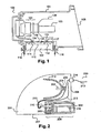
- FIG. figure 1 Such a projector device is schematically illustrated in FIG. figure 1 .
- a projector device 100 is essentially composed of an illuminating element 101 and a ballast 102 of the Xenon system type.
- the illuminating element 101 there is in particular a reflector 106 in which a light source 103 of the discharge lamp type has been placed.
- the light source 103 produces a light beam emerging from the illuminating element 101 at an exit surface 108, which constitutes the front part of the illuminating element 101.
- the light source 103 which rests on a light element lamp 104, is connected to a high voltage module 105 serving to supply it
- the high voltage module is powered by means of a first electrical connection 107, constituting an output beam, which is preferably shielded and which leaves the illuminating element 101 at a first opening, formed in a lower face 109 of the illuminating element 101, in which a first counterpart 110 of the connector has been arranged.
- This first counterpart 110 is intended to receive a first connector 111 of the ballast 102.
- the latter comprises a second connector 112, associated with a second counterpart 113 of the connector disposed at a second opening in the lower face 109 of the illuminating element 101.
- a second electrical connection 117, constituting an input beam, is connected to the second connector 112; it can convey various electrical signals, including a ballast power signal and various control signals from the vehicle.
- the connection between the ballast 102 and the illuminating element 101 is effected between the lower face 109 of the illuminating element 101 and an upper face 115 of the ballast 102, at a recess 114 formed in at least a part of the lower face and the rear face of the illuminating element 101, ie approximately under the assembly consisting of the reflector 106, the lamp holder element 104 and the high voltage module 105.
- the ballast 102 is fixed on the illuminating element 101 by means of at least two screws 116 which are disposed vertically in openings provided for this purpose.
- this zone corresponds to the zone located under the reflector element 101, which is also relatively accessible and facilitates the fitting accordingly: it is here that the heat produced by the light source 103 is the least important, and the lower part of the illuminating element 101 is easier to access than, for example, the rear part.
- the fact that the connector counterparts 110 and 113 are arranged vertically on the rear face 109 of the illuminating element 101 poses a first problem: in fact, the mold used to manufacture the illuminating element 101 opens in a horizontal direction, and the need to have the vertical connector counterparts requires the presence of drawers in the mold used. Since this mold is used for all the projector elements, including those operating with a halogen-type light source, this disadvantage, in addition to being penalizing in terms of complexity in producing the mold, unnecessarily increases the cost of the lamp. set of projectors elements.
- a third problem encountered with prior art projectors when associated with an add-on is that they are relatively bulky, the add-on module 102 having a large height due to its own design.
- a fourth problem encountered with the projectors devices of the state of the art when they are associated with a complementary module lies in the complexity of the mounting operation, in particular because of the fastening means used: in the state of the described technique, it must use at least two screws to secure the illuminating element 101 and the ballast 102. The more the number of screws is limited, the better the duration and simplicity of assembly.
- a device according to the preamble of claim 1 is known from document EP 1 136 749 A .
- the invention responds to the problems that have just been exposed.
- the invention proposes an illuminating element associated with a complementary module which has a great ease of assembly compared with those of the state of the art, in particular by reducing the number of elements involved for electrically connect the complementary module and the illuminating element, and which, in some embodiments, eliminates the need to provide drawers, to place the connector counterparts, in the manufacturing mold of the illuminating element.
- a recess is made under the reflector and an organization of the various elements of the device such that the complementary module no longer exceeds or exceeds a minimum out of the recess, at least in the sense of height. It is also planned to make the complementary module integral with the illuminating element by means of a single fastening element, for example a screw disposed at a contact plane defined by a front face of the complementary module and a wall. side of the recess. It is at this level of contact that the connector counter-part comes into contact with the contact areas of the electronic card of the complementary module.
- the invention therefore essentially relates to a lighting / signaling device according to claim 1.
- the insertion of the card as mentioned above is reversible: the card is removable. This feature is advantageous because it makes it easy to replace defective cards for example.
- elastic means are provided between the connector counterpart and the complementary module and / or the illuminating device. Their function is, in particular by their shape and elasticity, to compensate for the games that may exist between these different elements, to block any relative movement between them.
- Another object of the invention is a motor vehicle equipped with a projector device, comprising a complementary module, including the main characteristics that have been specified, with possibly at least one of the characteristics that have just been mentioned.
- the figure 2 shows a device 200 according to the invention in vertical section, which is composed in particular of an illuminating element 201 and a complementary module 202 of HID ballast type, which may include an electronic control card 216.
- a reflector 212 in which a light source 203, of the lamp type, has been placed. discharge.
- Reflector means a reflecting surface capable of returning light signals that meet it.
- the light source 203 produces a light beam that exits the illuminating element 201 at an exit surface 208, which constitutes the front portion of the illuminating element 201.
- the light source 203 which rests on a light element lamp 204, is connected to a high voltage module 205 for powering it.
- a recess 206 is formed in at least a portion of a lower surface 207 and a portion 209 of a rear surface 208 of the illuminating element 201, the orientations of these surfaces being defined by considering the projector device in an operating position usual on a motor vehicle, the exit surface of the light beam constituting the front face of the illuminating element.
- the recess 206 is of substantially parallelepiped shape in the example described, but its shape could be different in other embodiments of the invention.
- it has been sought to limit the space involved in the addition of the ballast type 202 add-on module. Two solutions are proposed, each of the two solutions possibly being able to be implemented alone or associated with the other solution. according to different embodiments of the projector device 200.
- the first solution consists in arranging, for example by clipping and with a little play, a counterpart 210 of the connector on the rear portion 209 of the illuminating element 201 which is situated at the level of the recess 206.
- the counter part of connector 210 with a suitable contact area of the complementary module can thus be done in a vertical plane, said contact plane or junction plane, that is by moving the ballast 202 in a horizontal direction towards the illuminating element 201, and no longer a vertical direction as was the case in the example described in figure 1 .
- This junction will be more particularly detailed at Figures 3 and 4 .
- a second solution possibly complementary to the first solution, in which the recess 206 is slightly extended horizontally, that is to say that it advances a little further under the reflector 212. Indeed, if it is not possible to increase the size of the recess in the direction of the height, otherwise the reflector 212 may be too close, nothing prevents it from being extended in the length direction for make it deeper.
- first electrical connection 213, constituting an input beam, which carries, from outside the projector device 200 to the connector counterpart 210, a set of power and control signals.
- This first electrical connection 213 enters the illuminating element 201 at an opening 214 to connect to the counterpart 210.
- a bypass at the counterpart 210 provides a second electrical connection, under the shape of an output beam, which supplies the light source 203.
- FIGS 3 and 4 show two embodiments of electrical connection between the complementary module 202 and the projector device 201.
- the connector counterpart 210 is fixed floatingly on the part 209 of the rear surface 208 of the illuminating element 201.
- a first seal 501 and a second seal 502 are disposed between the rear portion 209 and the counterpart 210.
- the role of the first seal 501 and the second seal 502 will be specified later.
- One end, accessible from the outside of the illuminating element 201, has an opening 303.
- the opening 303 is intended to receive one end of the electronic card 216.
- at least one set of electrical contact zones has been arranged.
- a first set of contact areas 306 and a second set of contact areas 307 are shown, respectively on an upper part and on a lower part of the electronic card 216.
- the Figures 3 and 4 being sectional views, they show only a single element of connectivity and a single contact zone of the sets to which they belong.
- the sets of connector elements are in fact constituted by a juxtaposition of identical or different type of connector elements arranged in the alignment of the visible connector element, parallel to the plane visible to the Figures 3 and 4 .
- the sets of contact zones consist of a juxtaposition of contact zones, preferably identical, arranged in alignment with the visible contact zone, parallel to the plane visible to the Figures 3 and 4 .
- the first set of contact zones 306, disposed on the upper part of the electronic card 216, is apparent to the figure 5 .
- the different contact zones 306 and 307 are arranged directly on the electronic card 216, that is to say that the electrical contacts are exposed on the surface of the electronic card 216. In some embodiments, they can be integrated in the initial thickness of the electronic card, in the manner of the contact areas of a chip in a smart card. So when the map electronic 216 is embedded in the opening 303 of the counterpart 210, the connection elements are directly in contact with the different contact areas.
- the relationship between the connector elements and the contact zones is bijective, that is to say that each contact zone is touched by a single connector element.
- each first contact zone of the first set 306 of contact zones is electrically connected to a second contact zone of the second set 307 of contact zones, the first contact zone and the second contact zone being preferably located one above the other.
- the electrical connection between two electrically connected contact zones is provided by via, or jumper, internal to the electronic card 216.
- a similar configuration is provided for the sets of connection elements, where each first element connector of the first set of connection elements 304 is electrically connected to a second connector element of the second set 305 of connector elements, the first connector element and the second connector element being preferably located one above the other. the other.
- Such an embodiment ensures a good quality of electrical connection between the connection elements and the contact areas.
- each contact zone and the connection element with which it is associated can be effected by means of an electrically conductive intermediate part 211 composed for example of a first set of contact tabs 308 and a second set of contact tabs 309, the contact tabs of the same set being arranged in alignment with the visible contact tab, parallel to the plane visible at the figure 5 .
- a contact tab is provided per contact zone. The two sets of tabs meet at a holding rod 310 which is intended to be inserted between the first set of connection elements 304 and the second set of connection elements 305 so as to ensure the electrical contact between the zones. contact and the appropriate connection elements.
- Means cooperating to center all the contact zones with respect to all the connection elements when the card electronics is embedded in the counterpart are provided in the invention.
- Such means may in particular involve one or more guide pins 311 on the counterpart 210 intended to fit into a suitable opening 312, visible to the figure 5 .
- connection elements and / or contact areas for example on a single face of the electronic card 216.
- a self-centering device of the set of connection elements on the set of contact zones is provided: it appears at the figure 8 in the form of two centering pins 500 disposed on the counterpart 210; these centering pins are intended to correctly orient the set of contact areas to the appropriate connection elements of the counterpart 210 when the illuminating element 201 and the ballast 202 fit into one another.
- the centering pins may be arranged on the complementary module 202, or may be replaced by chamfers arranged on the ballast 202 and / or the illuminating element 201.
- the screw 300 could be replaced by another mechanical means of attachment, for example a thrust spring which would be disposed behind the ballast 202 and which would exert on it a horizontal thrust to maintain operational the connection between the set of contact zones and the set of elements of connectivity.
- a thrust spring which would be disposed behind the ballast 202 and which would exert on it a horizontal thrust to maintain operational the connection between the set of contact zones and the set of elements of connectivity.
- one or more pairs of connecting elements may be provided, each pair consisting of a guiding slide 400 and a protruding element 401.
- the guide rails may be arranged on the illuminating element 201 or on the complementary module 202, the associated protruding element, that is to say belonging to the same pair of connecting elements, then being arranged on the element not supporting the guiding slide 400.
- the guide rails 400 may be disposed on any face of the illuminating element 201 or the complementary module 202, possibly at the level of the recess 206 when it exists.
- a protruding element 401 slides along a guide slide 400, it reaches a locking position, for example by mechanical stop, which corresponds to the final position of the complementary module, that is to say to its setting position. in use.
- a locking position for example by mechanical stop
- the complementary module reaches its blocking position, the set of contact zones is correctly embedded in the set of connection elements, that is to say that the mechanical stop and the electrical connection at the same time.
- the different centering means can be arranged in such a way that they also act in this way. moment.
- the guide rails 400 are arranged inside the illuminating element 201, the complementary module then being intended to be contained in the illuminating element 201, which has an advantage in terms of sealing of the device according to the invention.
- the guiding slides 400 gradually shrink, so as to brake by friction and then to stop, at the blocking position, the progression of the protruding elements 401.
- the protruding elements 401 can thus be locked in the slide rails. 400 guiding, thus able to maintain the complementary module 202 on the illuminating element 201 without using additional fastening means.
- the first seal 501 of the lip seal type, already visible to the Figures 3 and 4 , and which appears to Figures 6 and 8 , is disposed in the recess 206 to wrap the ballast 202 at its front, thus sealing the projector device 200 relative to the outside world.
- the first seal 501 can end with a membrane 502, visible for example at the figure 6 , which seals between the ballast 202 and the connector counterpart 210.
- This membrane 502 could take the form of a second seal, dissociated from the first seal 501, which would prevent any liquid infiltration between the ballast 202 and the ballast 202.
- illuminating element 201 at the fixing with clearance of the counterpart 210 on the illuminating element 201.
- a third seal 503, visible on the figure 7 seals the ballast 202 with respect to the outside; it is disposed at a junction between a heat sink 402 constituting the underside of the ballast 202 and the recesses 401 provided on the side walls of the ballast 202.
- a piece for example rubber, which surrounds the piece of counterpart 210 which is located in the illuminating element 201 and the electrical connections coming out of it; the rubber piece is, at a first end, in contact with the portion 209 of the rear face of the illuminating element, and at another end, facing downwards.
Description
La présente invention a pour objet un dispositif d'éclairage/signalisation, destiné essentiellement aux véhicules automobiles, ledit dispositif projecteur étant composé notamment d'un élément éclairant assemblé avec un module complémentaire encastrable se présentant sous la forme d'un boîtier. Le module complémentaire comporte un ensemble d'éléments électriques et/ou électroniques et/ou mécaniques destinés directement au fonctionnement du projecteur ou au fonctionnement de fonctions accessoires et/ou complexes associées au projecteur.The present invention relates to a lighting / signaling device, intended essentially for motor vehicles, said projector device being composed in particular of an illuminating element assembled with a built-in complementary module in the form of a housing. The complementary module comprises a set of electrical and / or electronic and / or mechanical elements intended directly for the operation of the projector or the operation of accessory and / or complex functions associated with the projector.
L'invention a essentiellement pour but de proposer une solution particulière dans la réalisation des contacts électriques entre l'élément éclairant et le module complémentaire; cette solution présente des avantages notamment en terme de facilité d'assemblage de l'élément éclairant avec le module complémentaire, et accessoirement en terme d'encombrement du module complémentaire lorsqu'il est assemblé avec l'élément éclairant, ou encore de simplicité des moules utilisés dans la réalisation de l'élément éclairant.The main purpose of the invention is to propose a particular solution in the realization of the electrical contacts between the illuminating element and the complementary module; this solution has advantages in particular in terms of ease of assembly of the illuminating element with the complementary module, and incidentally in terms of size of the complementary module when it is assembled with the illuminating element, or the simplicity of the molds used in the realization of the illuminating element.
Le domaine de l'invention est, d'une façon générale, celui des projecteurs de véhicule automobile. Dans ce domaine, on connaît différents types de projecteurs, parmi lesquels on trouve essentiellement :
- des feux de position, d'intensité et de portée faible ;
- des feux de croisement, ou codes, d'intensité plus forte et de portée sur la route avoisinant 70 mètres, qui sont utilisés essentiellement la nuit et dont la répartition du faisceau lumineux est telle qu'elle permet de ne pas éblouir le conducteur d'un véhicule croisé ;
- des feux de route longue portée, et des feux de complément de type longue portée, dont la zone de vision sur la route avoisine 200 mètres, et qui doivent être éteints lorsque l'on croise un autre véhicule afin de ne pas éblouir son conducteur ;
- des projecteurs perfectionnés, dits bimodes, qui cumulent les fonctions de feux de croisement et de feu de route en incorporant un cache amovible ;
- des feux anti-brouillard.
- position, intensity and low range lights;
- low beam, or codes, of greater intensity and range on the road of about 70 meters, which are used mainly at night and whose distribution of the light beam is such that it does not dazzle the driver of a crossover vehicle;
- long-range headlamps, and long-range supplement lights, whose vision zone on the road is approximately 200 meters, and which must be extinguished when crossing another vehicle so as not to dazzle its driver;
- advanced projectors, called dual mode, which combine the functions of low beam and high beam by incorporating a removable cover;
- fog lights.
L'association, selon l'invention, entre un élément éclairant et un module complémentaire peut être effectuée avec l'un quelconque de ces projecteurs. Le module complémentaire peut en effet par exemple contenir une carte électronique de type carte LCS (Light Control System en anglais, pour système de contrôle de l'éclairage), qui sert à la gestion de la mise en oeuvre de fonctions dites complexes (FBL, DBL, DRL, Cordy...) pour le projecteur auquel cette carte électronique est associée. Le module complémentaire peut également comporter une carte de contrôle pour piloter un élément mécanique de type actionneur. L'invention sera néanmoins plus particulièrement décrite dans le cadre d'un dispositif projecteur de type feu de croisement avec un module complémentaire de type ballast.The association according to the invention between an illuminating element and a complementary module can be performed with any of these projectors. For example, the complementary module may contain an LCS (Light Control System) card, which is used to manage the implementation of so-called complex functions (FBL, DBL, DRL, Cordy ...) for the projector to which this circuit board is associated. The complementary module may also include a control card for controlling a mechanical element of the actuator type. The invention will nevertheless be more particularly described in the context of a headlight device of the dipped beam type with a ballast-type complementary module.
Dans le contexte de l'invention, un ballast est un module complémentaire particulier contenu de préférence dans un dispositif projecteur de type feu de croisement utilisant comme source lumineuse une lampe à décharge. Plus particulièrement, dans l'invention, on fait référence aux ballasts à système Xénon, également appelés HID ( High Intensity Decharge en anglais, pour décharge de haute intensité), qui sont nécessaires pour créer et maintenir en vigueur un arc électrique utilisé dans les lampes à xénon. Un module électronique crée une haute tension au sein du ballast pour obtenir l'arc électrique au niveau de la source lumineuse utilisée. Dans ce type de projecteur, un module complémentaire de type ballast est donc indispensable pour fournir l'énergie nécessaire au bon fonctionnement du projecteur.In the context of the invention, a ballast is a particular complementary module preferably contained in a dipped-beam headlamp device using as a light source a discharge lamp. More particularly, in the invention, reference is made to Xenon system ballasts, also known as High Intensity Discharge (HID) ballasts, which are necessary to create and maintain an electric arc used in the lamps. to xenon. An electronic module creates a high voltage within the ballast to obtain the electric arc at the light source used. In this type of projector, a ballast-type add-on is therefore essential to provide the energy necessary for the proper functioning of the projector.
Cependant, l'intégration d'un tel module au sein du dispositif projecteur doit se faire en respectant un ensemble de contraintes :
- elle doit se faire au moyen d'une opération d'assemblage aussi simple que possible ;
- elle doit être peu encombrante;
- afin d'éviter tout endommagement des éléments contenus dans le ballast, elle doit tenir compte des fortes températures qui peuvent apparaître lors du fonctionnement du dispositif projecteur ;
- elle doit prendre en compte la nécessité des transmissions de signaux électriques entre les différents éléments du dispositif projecteur ;
- l'association entre l'élément éclairant et le module complémentaire ne doit pas entraîner de problèmes d'étanchéité pour l'une quelconque de ces pièces.
- it must be done by means of an assembly operation as simple as possible;
- it must be compact;
- in order to avoid damage to the elements contained in the ballast, it must take into account the high temperatures that may occur during the operation of the projector device;
- it must take into account the need for transmissions of electrical signals between the different elements of the projector device;
- the association between the illuminating element and the add-on module shall not cause any sealing problems for any of the these parts.
Dans l'état de la technique, on a proposé notamment un dispositif projecteur qui tente de respecter ces différentes contraintes. Un tel dispositif projecteur est illustré de façon schématique à la
Sur cette figure, un dispositif projecteur 100 est essentiellement composé d'un élément éclairant 101 et d'un ballast 102 de type système Xénon. Dans l'élément éclairant 101, on trouve notamment un réflecteur 106 dans lequel on a placé une source lumineuse 103, de type lampe à décharge. La source lumineuse 103 produit un faisceau lumineux qui sort de l'élément éclairant 101 au niveau d'une surface de sortie 108, qui constitue la partie avant de l'élément éclairant 101. La source lumineuse 103, qui repose sur un élément porte-lampe 104, est connectée à un module haute tension 105 servant à l'alimenterIn this figure, a
Le module haute tension est alimenté au moyen d'un première liaison électrique 107, constituant un faisceau de sortie, qui est de préférence blindée et qui sort de l'élément éclairant 101 au niveau d'une première ouverture, ménagée dans une face inférieure 109 de l'élément éclairant 101, dans laquelle on a disposé une première contre-partie 110 de connecteur. Cette première contre-partie 110 est destinée à recevoir un premier connecteur 111 du ballast 102. Ce dernier comporte un deuxième connecteur 112, associé à une deuxième contre-partie 113 de connecteur disposée au niveau d'une deuxième ouverture ménagée dans la face inférieure 109 de l'élément éclairant 101. Une deuxième liaison électrique 117, constituant un faisceau d'entrée, est reliée au deuxième connecteur 112; elle permet d'acheminer différents signaux électriques, notamment un signal d'alimentation du ballast et différents signaux de contrôle provenant du véhicule.The high voltage module is powered by means of a first
La solidarisation entre le ballast 102 et l'élément éclairant 101 s'effectue entre la face inférieure 109 de l'élément éclairant 101 et une face supérieure 115 du ballast 102, au niveau d'un évidement 114 ménagé dans au moins une partie de la face inférieure et de la face arrière de l'élément éclairant 101, c'est à dire approximativement sous l'ensemble constitué par le réflecteur 106, l'élément porte-lampe 104 et le module haute tension 105. Le ballast 102 est fixé sur l'élément éclairant 101 au moyen d'au moins deux vis 116 qui viennent se disposer verticalement dans des ouvertures prévues à cet effet.The connection between the
Le choix de la disposition du ballast 102 s'effectue notamment en considérant la zone la moins chaude du dispositif projecteur. Généralement, cette zone correspond à la zone située sous l'élément réflecteur 101, qui par ailleurs est assez accessible et facilite en conséquence le montage: c'est à cet endroit que la chaleur produite par la source de lumière 103 est la moins importante, et la partie inférieure de l'élément éclairant 101 est plus facile d'accès que, par exemple, la partie arrière.The choice of the arrangement of the
L'assemblage entre l'élément éclairant et le module complémentaire tel qu'il vient d'être décrit comporte un certain nombre d'inconvénients :The assembly between the illuminating element and the complementary module as just described has a number of disadvantages:
Tout d'abord, le fait que les contre-parties de connecteur 110 et 113 soient disposées verticalement sur la face arrière 109 de l'élément éclairant 101 pose un premier problème : en effet, le moule qui sert à fabriquer l'élément éclairant 101 s'ouvre selon une direction horizontale, et la nécessité de pouvoir disposer des contre-parties de connecteur verticales impose la présence de tiroirs dans le moule utilisé. Ce moule étant utilisé pour l'ensemble des éléments projecteurs, y compris ceux fonctionnant avec une source lumineuse de type halogène, ce désavantage, en plus d'être pénalisant en terme de complexité dans la réalisation du moule, augmente inutilement le coût de l'ensemble des éléments projecteurs.Firstly, the fact that the
La présence de deux connecteurs est également un problème en soi ; en effet, plus le nombre de connecteurs est important, plus le montage est délicat et long à réaliser.The presence of two connectors is also a problem in itself; Indeed, the more the number of connectors is important, the more the assembly is delicate and long to achieve.
Un troisième problème rencontré avec les dispositifs projecteurs de l'état de la technique lorsqu'ils sont associés avec un module complémentaire est qu'ils sont relativement encombrants, le module complémentaire 102 ayant une hauteur importante du fait de sa propre conception.A third problem encountered with prior art projectors when associated with an add-on is that they are relatively bulky, the add-on
Un quatrième problème rencontré avec les dispositifs projecteurs de l'état de la technique lorsqu'ils sont associés avec un module complémentaire réside dans la complexité de l'opération de montage, notamment en raison des moyens de fixation utilisés: dans l'état de la technique décrit, on doit utiliser au moins deux vis pour solidariser l'élément éclairant 101 et le ballast 102. Plus le nombre de vis est limité, meilleure est la durée et la simplicité de montage.A fourth problem encountered with the projectors devices of the state of the art when they are associated with a complementary module lies in the complexity of the mounting operation, in particular because of the fastening means used: in the state of the described technique, it must use at least two screws to secure the
Un dispositif selon le préambule de la revendication 1 est connu du document
Le dispositif selon l'invention répond aux problèmes qui viennent d'être exposés. D'une façon générale, on propose dans l'invention un élément éclairant associé avec un module complémentaire qui présente une grande facilité d'assemblage par rapport à ceux de l'état de la technique, notamment en réduisant le nombre d'éléments intervenant pour connecter électriquement le module complémentaire et l'élément éclairant, et qui, dans certains exemples de réalisation, supprime la nécessité de prévoir des tiroirs, pour placer les contre-parties de connecteur, dans le moule de fabrication de l'élément éclairant.The device according to the invention responds to the problems that have just been exposed. In general terms, the invention proposes an illuminating element associated with a complementary module which has a great ease of assembly compared with those of the state of the art, in particular by reducing the number of elements involved for electrically connect the complementary module and the illuminating element, and which, in some embodiments, eliminates the need to provide drawers, to place the connector counterparts, in the manufacturing mold of the illuminating element.
Dans l'invention, on prévoit par ailleurs une organisation différente des liaisons électriques qui permet de n'utiliser désormais qu'une unique contre-partie de connecteur sur l'élément éclairant. De plus, on peut prévoir une disposition du module complémentaire qui permet de limiter l'augmentation du volume global du dispositif projecteur, notamment dans le sens de la hauteur, tout en améliorant son étanchéité. Enfin, on limite le nombre de moyens de fixation.In the invention, there is also provided a different organization of electrical connections that allows to use now only a single connector counterpart on the illuminating element. In addition, provision may be provided for the complementary module that limits the increase in the overall volume of the projector device, especially in the direction of height, while improving its sealing. Finally, the number of fixing means is limited.
A cet effet, dans l'invention, on propose une solution différente de celle décrite à la
Dans un exemple particulier de réalisation du dispositif selon l'invention, on réalise un évidement sous le réflecteur et une organisation des différents éléments du dispositif tels que le module complémentaire ne dépasse plus ou dépasse un minimum hors de l'évidement, au moins dans le sens de la hauteur. On prévoit par ailleurs de réaliser la solidarisation du module complémentaire avec l'élément éclairant au moyen d'un élément unique de fixation, par exemple une vis disposée au niveau d'un plan de contact défini par une face avant du module complémentaire et une paroi latérale de l'évidement. C'est au niveau de ce plan de contact que la contre-partie de connecteur entre en contact avec les zones de contact de la carte électronique du module complémentaire.In a particular embodiment of the device according to the invention, a recess is made under the reflector and an organization of the various elements of the device such that the complementary module no longer exceeds or exceeds a minimum out of the recess, at least in the sense of height. It is also planned to make the complementary module integral with the illuminating element by means of a single fastening element, for example a screw disposed at a contact plane defined by a front face of the complementary module and a wall. side of the recess. It is at this level of contact that the connector counter-part comes into contact with the contact areas of the electronic card of the complementary module.
L'invention concerne donc essentiellement un dispositif d'éclairage/signalisation selon la revendication 1.The invention therefore essentially relates to a lighting / signaling device according to claim 1.
Le dispositif projecteur selon l'invention peut présenter une ou plusieurs des caractéristiques secondaires suivantes :
- les zones de contact électrique sont réparties sur au moins deux faces du module complémentaire.
- les zones de contact électrique sont disposées sur une unique face du module complémentaire.
- la contre-partie de connecteur comporte une ouverture, dans laquelle la carte électronique vient s'encastrer/s'insérer, et dans laquelle est disposé l'ensemble des éléments de connectique.
- les zones de contact électrique sont réparties en un premier ensemble de zones de contact électrique, disposées sur une première face de la carte électronique, et un deuxième ensemble de zones de contact électrique, disposées sur une deuxième face de la carte électronique, chaque zone de contact du premier ensemble étant relié électriquement à une zone de contact du deuxième ensemble.
- le dispositif projecteur comporte des moyens coopérant pour centrer l'ensemble des zones de contact par rapport à l'ensemble des éléments de connectique lorsque la carte électronique vient s'encastrer dans la contre-partie.
- le module complémentaire est un ballast de type système à Xénon - ou HID- ou un module comprenant une carte électronique gérant au moins une fonction associée à l'élément éclairant.
- le dispositif projecteur comporte un évidement ménagé dans au moins une partie de la face inférieure et une partie de la face arrière de l'élément éclairant, la contre-partie de connecteur étant disposée dans une ouverture ménagée dans la face arrière de l'élément éclairant, au niveau de l'évidement.
- le dispositif projecteur comporte un premier moyen d'étanchéité du type joint disposé dans l'évidement pour venir envelopper une extrémité de connexion du module complémentaire et rendre ainsi étanche le dispositif projecteur.
- le premier joint est du type joint à lèvre ou joint de compression.
- le dispositif projecteur comporte un deuxième moyen d'étanchéité du type joint disposé dans l'évidement pour venir envelopper partiellement la contre-partie du connecteur et rendre ainsi étanche une jonction entre la contre-partie de connecteur et le module complémentaire.
- le dispositif projecteur comporte un troisième moyen d'étanchéité du type joint disposé entre un drain thermique, constituant une partie inférieure du module complémentaire, et un capot du module complémentaire.
- le dispositif projecteur comporte une entrée d'alimentation unique pour recevoir un ensemble de signaux depuis l'extérieur du dispositif projecteur, lesdits signaux étant transmis, via une première liaison conductrice, à la contre-partie de connecteur, une deuxième liaison conductrice interne à l'élément éclairant assurant la transmission de signaux entre la contre-partie de connecteur et un module haute tension associé à la source lumineuse.
- le dispositif projecteur comporte deux paires d'éléments d'assemblage.
- chaque glissière de guidage est disposée sur l'élément éclairant et chaque élément protubérant d'une paire d'éléments d'assemblage est disposé sur le module complémentaire.
- les glissières de guidage sont disposées sur des parois de l'élément éclairant qui définissent l'évidement.
- the electrical contact zones are distributed over at least two faces of the complementary module.
- the electrical contact zones are arranged on a single face of the complementary module.
- the counterpart of connector comprises an opening, in which the electronic card is embedded / insert, and in which is disposed all the connection elements.
- the electrical contact zones are distributed in a first set of electrical contact zones, arranged on a first face of the electronic card, and a second set of electrical contact zones, arranged on a second face of the electronic card, each zone of contact of the first set being electrically connected to a contact area of the second set.
- the projector device comprises cooperating means for centering all the contact zones with respect to all the elements of the connectivity when the electronic card is embedded in the counterpart.
- the complementary module is a Xenon system - or HID- type ballast or a module comprising an electronic card managing at least one function associated with the illuminating element.
- the projector device comprises a recess formed in at least a portion of the lower face and a portion of the rear face of the illuminating element, the connector counterpart being disposed in an opening in the rear face of the illuminating element , at the level of the recess.
- the projector device comprises a first sealing means of the seal type disposed in the recess for coming to wrap a connecting end of the complementary module and thus sealing the projector device.
- the first seal is of the type lip seal or compression seal.
- the projector device comprises a second sealing means of the seal type disposed in the recess for partially enclosing the counter part of the connector and thus sealing a junction between the connector counter-part and the complementary module.
- the projector device comprises a third sealing means of the seal type disposed between a heat sink, constituting a lower part of the complementary module, and a cover of the complementary module.
- the projector device comprises a single power supply input for receiving a set of signals from outside the projector device, said signals being transmitted, via a first conductive connection, to the connector counterpart, a second internal conductive link to the illuminating element ensuring the transmission of signals between the connector counterpart and a high voltage module associated with the light source.
- the projector device comprises two pairs of connecting elements.
- each guide rail is arranged on the illuminating element and each protruding element of a pair of connecting elements is arranged on the complementary module.
- the guide rails are arranged on walls of the illuminating element which define the recess.
Selon une variante, l'insertion de la carte telle que mentionnée plus haut est réversible : la carte est amovible. Cette caractéristique est avantageuse, car elle permet de remplacer aisément les cartes défectueuses par exemple.According to one variant, the insertion of the card as mentioned above is reversible: the card is removable. This feature is advantageous because it makes it easy to replace defective cards for example.
On prévoit avantageusement des moyens élastiques entre la contre-partie de connecteur et le module complémentaire et/ou le dispositif éclairant. Leur fonction est, notamment par leur forme et leur élasticité, de compenser les jeux qui peuvent exister entre ces différents éléments, de bloquer tout mouvement relatif entre ceux-ci.Advantageously, elastic means are provided between the connector counterpart and the complementary module and / or the illuminating device. Their function is, in particular by their shape and elasticity, to compensate for the games that may exist between these different elements, to block any relative movement between them.
Un autre objet de l'invention est un véhicule automobile équipé d'un dispositif projecteur, comportant un module complémentaire, incluant les caractéristiques principales qui ont été précisées, avec éventuellement au moins une des caractéristiques qui viennent d'être mentionnées.Another object of the invention is a motor vehicle equipped with a projector device, comprising a complementary module, including the main characteristics that have been specified, with possibly at least one of the characteristics that have just been mentioned.
L'invention et ses différentes applications seront mieux comprises à la lecture de la description qui suit et à l'examen des figures qui l'accompagnent. Celles-ci ne sont présentées qu'à titre indicatif et nullement limitatif de l'invention. Les figures montrent :
- à la
figure 1 , déjà décrite, une représentation d'une association entre un dispositif projecteur et un module complémentaire dans l'état de la technique ; - à la
figure 2 , une représentation schématique d'une vue en coupe et de face d'une association entre un dispositif projecteur et un module complémentaire selon l'invention; - à la
figure 3 , une représentation schématique de l'assemblage, selon un premier mode de réalisation de l'invention, entre le dispositif projecteur et le module complémentaire ; - à la
figure 4 , une représentation schématique de l'assemblage, selon un deuxième mode de réalisation de l'invention, entre le dispositif projecteur et le module complémentaire ; - à la
figure 5 , une représentation partielle, en perspective, d'un exemple de réalisation de la carte électronique intervenant dans le dispositif selon l'invention ; - à la
figure 6 , une représentation plus détaillée des différents éléments intervenant dans la solidarisation entre le dispositif projecteur et le module complémentaire avec un montage de la contre-partie de connecteur sur l'élément éclairant ne faisant pas partie de l'invention; - à la
figure 7 , une représentation schématique d'une vue en coupe et de gauche d'une association entre un dispositif projecteur et un module complémentaire selon l'invention; - à la
figure 8 , une représentation schématique en perspective d'une partie du dispositif selon l'invention.
- to the
figure 1 , already described, a representation of an association between a projector device and a complementary module in the state of the art; - to the
figure 2 , a schematic representation of a sectional and front view of an association between a projector device and a complementary module according to the invention; - to the
figure 3 , a schematic representation of the assembly, according to a first embodiment of the invention, between the projector device and the complementary module; - to the
figure 4 , a schematic representation of the assembly, according to a second embodiment of the invention, between the projector device and the complementary module; - to the
figure 5 , a partial representation, in perspective, of an exemplary embodiment of the electronic card involved in the device according to the invention; - to the
figure 6 , a more detailed representation of the various elements involved in the connection between the projector device and the complementary module with a mounting of the connector counterpart on the illuminating element not forming part of the invention; - to the
figure 7 , a schematic representation of a sectional view and left of an association between a projector device and a complementary module according to the invention; - to the
figure 8 , a schematic representation in perspective of a part of the device according to the invention.
Sur les différentes figures, les éléments qui sont communs à plusieurs figures auront conservé les mêmes références.In the different figures, the elements that are common to several figures will have retained the same references.
La
Un évidement 206 est ménagé dans au moins une partie d'une surface inférieure 207 et une partie 209 d'une surface arrière 208 de l'élément éclairant 201, les orientations de ces surfaces étant définies en considérant le dispositif projecteur dans une position de fonctionnement habituel sur un véhicule automobile, la surface de sortie du faisceau lumineux constituant la face avant de l'élément éclairant. L'évidement 206 est de forme sensiblement parallélépipédique dans l'exemple décrit, mais sa forme pourrait être différente dans d'autres modes de réalisation de l'invention. Dans le dispositif projecteur 200, on a cherché à limiter l'encombrement lié à l'ajout du module complémentaire de type ballast 202. Deux solutions sont proposées, chacune des deux solutions pouvant éventuellement être mise en oeuvre seule ou associée à l'autre solution selon différents modes de réalisation du dispositif projecteur 200.A
La première solution consiste à disposer, par exemple par clipsage et avec un peu de jeu, une contre-partie 210 de connecteur sur la partie arrière 209 de l'élément éclairant 201 qui se situe au niveau de l'évidement 206. La jonction de la contre partie de connecteur 210 avec une zone de contact appropriée du module complémentaire peut ainsi se faire selon un plan vertical, dit plan de contact ou plan de jonction, c'est à dire en déplaçant le ballast 202 selon une direction horizontale vers l'élément éclairant 201, et non plus une direction verticale comme c'était le cas dans l'exemple décrit à la
Une légère augmentation de la largeur du dispositif pourrait alors cependant être constatée. C'est pourquoi dans l'invention, on propose une deuxième solution, éventuellement complémentaire de la première solution, selon laquelle l'évidement 206 est légèrement prolongé horizontalement, c'est à dire qu'il avance un peu plus sous le réflecteur 212. En effet, s'il n'est pas possible d'augmenter la taille de l'évidement dans le sens de la hauteur, sous peine de trop approcher le réflecteur 212, rien n'empêche de le prolonger dans le sens de la longueur pour le rendre plus profond.A slight increase in the width of the device could then however be noted. Therefore, in the invention, there is provided a second solution, possibly complementary to the first solution, in which the
De plus, le fait de disposer désormais d'un plan de contact vertical permet d'améliorer la jonction en terme d'étanchéité ; en effet, de l'eau formée par condensation au sein de l'élément éclairant 201 peut éventuellement s'infiltrer le long d'une jonction horizontale, mais pas le long d'une jonction verticale. Dans les exemples qui viennent d'être décrits, on peut supprimer le jeu entre la contre-partie 210 et la partie 209 de la face arrière, par exemple en utilisant un élément souple, par exemple un joint, solidaire du ballast 202.In addition, the fact of now having a vertical contact plane makes it possible to improve the junction in terms of sealing; in fact, water formed by condensation within the illuminating
Par ailleurs, dans l'invention, on propose une organisation de différentes liaisons électriques conductrices qui permet de se limiter à la présence d'une unique contre-partie 210 de connecteur. En effet, on prévoit une première liaison électrique 213, constituant un faisceau d'entrée, qui transporte, depuis l'extérieur du dispositif projecteur 200 jusqu'à la contre-partie de connecteur 210, un ensemble de signaux d'alimentation et de contrôle. Cette première liaison électrique 213 entre dans l'élément éclairant 201 au niveau d'une ouverture 214 pour aller se connecter sur la contre-partie 210. Une dérivation au niveau de la contre-partie 210 permet d'obtenir une deuxième liaison électrique, sous la forme d'un faisceau de sortie, qui permet d'alimenter la source lumineuse 203.Furthermore, in the invention, there is provided an organization of different conductive electrical connections which makes it possible to limit itself to the presence of a
Il est à présent essentiellement fait référence aux
L'ouverture 303 est destinée à recevoir une extrémité de !a carte électronique 216. Sur cette extrémité, on a, selon l'invention, disposé au moins un ensemble de zones de contact électrique. Pour les exemples illustrés, un premier ensemble de zones de contact 306 et un deuxième ensemble de zones de contact 307 sont représentés, respectivement sur une partie supérieure et sur une partie inférieure de la carte électronique 216. Les
Selon l'invention, les différentes zones de contact 306 et 307 sont disposées directement sur la carte électronique 216, c'est à dire que les contacts électriques sont mis à nu sur la superficie de la carte électronique 216. Dans certains modes de réalisation, ils peuvent être intégrés dans l'épaisseur initiale de la carte électronique, à la manière des plages de contact d'une puce dans une carte à puce. Ainsi, lorsque la carte électronique 216 est encastrée dans l'ouverture 303 de la contre-partie 210, les éléments de connectique sont directement en contact avec les différentes zones de contact. De préférence, la relation entre les éléments de connectique et les zones de contact est bijective, c'est à dire que chaque zone de contact est touchée par un unique élément de connectique.According to the invention, the
Dans un exemple particulier de réalisation, chaque première zone de contact du premier ensemble 306 de zones de contact est reliée électriquement à une deuxième zone de contact du deuxième ensemble 307 de zones de contact, la première zone de contact et la deuxième zone de contact étant de préférence situées l'une au-dessus de l'autre. La liaison électrique entre deux zones de contact électriquement reliées est assurée par des via, ou pontages, internes à la carte électronique 216. Dans un tel cas de figure, une configuration similaire est prévue pour les ensembles de éléments de connectique, où chaque premier élément de connectique du premier ensemble de éléments de connectique 304 est relié électriquement à un deuxième élément de connectique du deuxième ensemble 305 de éléments de connectique, le premier élément de connectique et le deuxième élément de connectique étant de préférence situés l'un au-dessus de l'autre. Une telle réalisation assure une bonne qualité de connexion électrique entre les éléments de connectique et les zones de contact.In a particular embodiment, each first contact zone of the
Comme illustré à la
Des moyens coopérant pour centrer l'ensemble des zones de contact par rapport à l'ensemble des éléments de connectique lorsque la carte électronique vient s'encastrer dans la contre-partie sont prévus dans l'invention. De tels moyens peuvent notamment faire intervenir un ou plusieurs pions de guidage 311 sur la contre-partie 210 destinés à venir s'emboîter dans une ouverture appropriée 312, visible à la
Dans d'autres exemples de réalisation, on prévoit dans l'invention de ne disposer qu'un unique ensemble de éléments de connectique et/ou de zones de contact, par exemple sur une unique face de la carte électronique 216.In other exemplary embodiments, provision is made in the invention to have only a single set of connection elements and / or contact areas, for example on a single face of the
Il est à présent essentiellement fait référence aux
A la
Un dispositif d'auto-centrage de l'ensemble de éléments de connectique sur l'ensemble de zones de contact est prévu : il apparaît à la
Dans un autre exemple de réalisation, la vis 300 pourrait être remplacée par un autre moyen mécanique de fixation, par exemple un ressort de poussée qui serait disposé derrière le ballast 202 et qui exercerait sur lui une poussée horizontale pour maintenir opérationnelle la liaison entre l'ensemble de zones de contact et l'ensemble de éléments de connectique.In another embodiment, the
Selon l'invention, des rails de guidage 400, ou glissières, visibles aux
Selon l'invention, on peut prévoir une ou plusieurs paires d'éléments d'assemblage, chaque paire étant constituée d'une glissière de guidage 400 et d'un élément protubérant 401. Les glissières de guidage peuvent être disposées sur l'élément éclairant 201 ou sur le module complémentaire 202, l'élément protubérant associé, c'est à dire appartenant à la même paire d'éléments d'assemblage, étant alors disposé sur l'élément ne supportant pas la glissière de guidage 400. Selon les différents exemples de réalisation envisagés pour le dispositif selon l'invention, les glissières de guidage 400 peuvent être disposées sur une face quelconque de l'élément éclairant 201 ou du module complémentaire 202, éventuellement au niveau de l'évidement 206 lorsqu'il existe.According to the invention, one or more pairs of connecting elements may be provided, each pair consisting of a guiding
Lorsqu'un élément protubérant 401 glisse le long d'une glissière de guidage 400, il atteint une position de blocage, par exemple par butée mécanique, qui correspond à la position finale du module complémentaire, c'est à dire à sa position de mise en service. Dans l'invention, on prévoit que lorsque le module complémentaire atteint sa position de blocage, l'ensemble de zones de contact est correctement encastrée dans l'ensemble de éléments de connectique, c'est à dire que la butée mécanique et la connexion électrique s'effectuent au même moment. Afin que la connexion électrique s'effectue de façon satisfaisante, les différents moyens de centrage peuvent être disposés de façon à ce qu'ils agissent également à ce moment.When a
Dans un exemple qui ne fait pas partie de la présente invention, on dispose les glissières de guidage 400 à l'intérieur même de l'élément éclairant 201, le module complémentaire étant alors destiné à être contenu dans l'élément éclairant 201, ce qui présente un avantage en terme d'étanchéité du dispositif selon l'invention.In an example which does not form part of the present invention, the
Selon une variante, les glissières de guidage 400 se rétrécissent progressivement, de façon à freiner par frottement puis à stopper, au niveau de la position de blocage, la progression des éléments protubérants 401. Les éléments protubérants 401 peuvent ainsi être bloqués dans les glissières de guidage 400, pouvant ainsi assurer le maintien du module complémentaire 202 sur l'élément éclairant 201 sans utiliser de moyens de fixation supplémentaires.According to one variant, the guiding slides 400 gradually shrink, so as to brake by friction and then to stop, at the blocking position, the progression of the
Afin d'assurer une parfaite étanchéité du dispositif selon l'invention, différents joints peuvent être présents :In order to ensure perfect sealing of the device according to the invention, different joints may be present:
Le premier joint 501, du type joint à lèvre, déjà visible aux
Un troisième joint 503, visible sur la
On peut aussi prévoir un moyen d'étanchéité de type joint entre la contre-partie (210) de connecteur et la liaison conductrice (215) représentée en
Pour améliorer encore l'étanchéité, on prévoit l'ajout d'une pièce, par exemple en caoutchouc, qui entoure le morceau de contre-partie 210 qui se situe dans l'élément éclairant 201 et les liaisons électriques qui en sortent; la pièce en caoutchouc est, à une première extrémité, en contact avec la partie 209 de la face arrière de l'élément éclairant, et à une autre extrémité, orientée vers le bas.To further improve the seal, it is expected the addition of a piece, for example rubber, which surrounds the piece of
Claims (17)
- Lighting/signalling device (200) intended for a motor vehicle, including a lighting element (201) comprising at least a reflector (212), a light source (203) and a housing having a set of lateral faces including a rear face, a lower face and an upper face, characterised in that said lighting device comprises a complementary module (202) placed on the outside of the housing of the lighting element (201) and with which it is associated by means of at least a pair of assembly elements formed by a guiding slide (400) and a protruding element (401), the protruding element (401) being insertable at least at one end of the guiding slide (400) with which it is paired, and being slidable in this guiding slide (400), each of the assembly elements (400; 401) of a pair of assembly elements being placed either on the lighting element (201) or on a complementary module (202) intended to be associated with the lighting element (201), the two assembly elements of an assembly pair not being placed together on the lighting element (201) or on the complementary module (202), the lighting element (201) having at least one connector counterpart (210) placed in a floating manner in an opening formed in the rear surface (208) of the lighting element (201), said connector counterpart (210) having a set of connection elements (304; 305) intended to come into contact with a set of electrical contact areas (306; 307) of said complementary module (202), each electrical contact area (306; 307) being placed so as to be directly accessible, for the connection element for which it is intended, on a surface part of an electronic circuit card (216) of the complementary module (202), the set of contact areas (306; 307) and the set of connection elements (304; 305) coming into contact when at least one protruding element (401) of an assembly pair is at the end of its travel in the guiding slide (400) with which it is associated.
- Device (200) according to the preceding claim, characterised in that the electrical contact areas (306; 307) are distributed on at least two faces of the complementary module (202).
- Device (200) according to Claim 1, characterised in that the electrical contact areas (306) are placed on a single face of the complementary module (202).
- Device (200) according to any of the preceding claims, characterised in that the connector counterpart (210) has an opening (303) into which the electronic circuit card (216) is fitted and/or inserted, and in which the set of connection elements (304; 305) is placed.
- The device (200) according to any of the preceding claims, characterised in that resilient means are provided between the connector counterpart (210) and the complementary module (202) and/or the lighting device (201).
- Device (200) according to Claim 4 and Claim 2, characterised in that the electrical contact areas (306; 307) are distributed in a first set (306) of electrical contact areas, placed on a first face of the electronic circuit card (216), and a second set (307) of electrical contact areas, placed on a second face of the electronic circuit card (216), each contact area of the first set of contact areas (306) being electrically connected to a contact area of the second set of contact areas (307).
- Device (200) according to at least one of Claims 4 to 6, characterised in that it includes means (311; 312) which interact to centre the set of contact areas (306; 307) with respect to the set of connection elements (304; 305) when the electronic circuit card (216) is fitted in the counterpart (210).
- Device (200) according to any of the preceding claims, characterised in that the complementary module (202) is a ballast of the xenon system type or a module comprising an electronic circuit card controlling at least one function associated with the lighting element (201).
- Device (200) according to at least one of the preceding claims, characterised in that it includes a recess (206) formed in at least a part of the lower face and a part (209) of the rear face of the lighting element, the connector counterpart (210) being placed in an opening formed in the rear face of the lighting element, at the level of the recess (206).
- Device according to the preceding claim, characterised in that it includes a first sealing means of the gasket type (501) placed in the recess (206) so as to enclose a connection end of the complementary module (202), thus sealing the lighting device (200).
- Device (200) according to at least one of Claims 9 and 10, characterised in that it includes a second sealing means of the gasket type (502) placed in the recess (206) so as to partially enclose the counterpart (210), thus sealing a junction between the connector counterpart (210) and the complementary module (202).
- Device (200) according to at least one of Claims 9 and 11, characterised in that it includes a third sealing means of the gasket type (503) placed between a cover of the complementary module (202), which forms a lower part of the complementary module (202), and a casing of the complementary module (202).
- Device (200) according to at least one of the preceding claims, characterised in that it includes a single power supply input (214) for receiving a set of signals from outside the light device (200), said signals being transmitted via a first conducting link (213) to the connector counterpart (210), a second conducting link (215) inside the lighting element (201) enabling signals to be transmitted between the connector counterpart (210), and a high voltage module (205) associated with the light source (203).
- Device according to Claim 13, characterised in that a sealing means of the gasket type is provided between the connector counterpart (210) and the conducting link (215).
- Device (200) according to any of the preceding claims, characterised in that it comprises two pairs of assembly elements (400; 401).
- Device (200) according to at least one of the preceding claims, characterised in that each guiding slide is placed on the lighting element and in that each protruding element (401) of a pair of assembly elements is placed on the complementary module (401).
- Device (200) according to the preceding claim and Claim 9, characterised in that the guiding slides (400) are placed on walls of the lighting element (201) which form the recess (206).
Applications Claiming Priority (2)
| Application Number | Priority Date | Filing Date | Title |
|---|---|---|---|
| FR0301570A FR2850729B1 (en) | 2003-02-04 | 2003-02-04 | PROJECTOR DEVICE EQUIPPED WITH AN INSERTIONABLE COMPLEMENTARY MODULE FOR A MOTOR VEHICLE |
| FR0301570 | 2003-02-04 |
Publications (3)
| Publication Number | Publication Date |
|---|---|
| EP1445533A2 EP1445533A2 (en) | 2004-08-11 |
| EP1445533A3 EP1445533A3 (en) | 2008-10-29 |
| EP1445533B1 true EP1445533B1 (en) | 2014-12-10 |
Family
ID=32606035
Family Applications (1)
| Application Number | Title | Priority Date | Filing Date |
|---|---|---|---|
| EP04290248.6A Expired - Lifetime EP1445533B1 (en) | 2003-02-04 | 2004-01-30 | Lighting or signalling device for motor vehicle with built-in complementary module |
Country Status (5)
| Country | Link |
|---|---|
| US (1) | US7222990B2 (en) |
| EP (1) | EP1445533B1 (en) |
| JP (1) | JP4554225B2 (en) |
| ES (1) | ES2532367T3 (en) |
| FR (1) | FR2850729B1 (en) |
Families Citing this family (12)
| Publication number | Priority date | Publication date | Assignee | Title |
|---|---|---|---|---|
| FR2843445B1 (en) | 2002-08-08 | 2005-05-27 | Valeo Vision | PROJECTOR DEVICE EQUIPPED WITH A COMPLEMENTARY MODULE FOR A MOTOR VEHICLE |
| FR2852381B1 (en) * | 2003-03-14 | 2005-05-27 | Valeo Vision | SHIELDING DEVICE FOR CONNECTION BETWEEN A PROJECTOR AND A COMPLEMENTARY MODULE |
| JP4572796B2 (en) * | 2004-11-11 | 2010-11-04 | 株式会社デンソー | Discharge lamp lighting device |
| FR2922714B1 (en) * | 2007-10-19 | 2010-03-12 | Valeo Vision | ELECTRICAL SUPPLY DEVICE FOR A DISCHARGE LAMP COMPRISING A BALLAST SHIELD AND A BEAM SHIELD CONNECTED IN PARLLELE TO A COMMON POTENTIAL |
| US8070338B2 (en) * | 2008-04-07 | 2011-12-06 | General Electric Company | Three-mode integrated headlamp |
| EP2793317B1 (en) * | 2013-04-15 | 2016-03-02 | Siemens Aktiengesellschaft | Connector |
| US9086203B2 (en) * | 2013-11-06 | 2015-07-21 | GM Global Technology Operations LLC | Sealed bulb connector system for a headlamp assembly |
| DE102017106948A1 (en) * | 2017-03-31 | 2018-10-04 | HELLA GmbH & Co. KGaA | Light module for a headlight of a vehicle with a digitally controllable light distribution means, in particular LCD headlights |
| JP2018206724A (en) * | 2017-06-09 | 2018-12-27 | 株式会社小糸製作所 | Light source module |
| FR3102644B1 (en) | 2019-10-29 | 2022-01-07 | Psa Automobiles Sa | Device for supporting and connecting an electronic card for controlling a motor vehicle lighting or signaling module |
| KR102512377B1 (en) * | 2021-08-10 | 2023-03-21 | 현대모비스 주식회사 | Led driver module and car including the same |
| FR3139772A1 (en) * | 2022-09-20 | 2024-03-22 | Psa Automobiles Sa | Optical unit for a motor vehicle equipped with simplified electrical connection means |
Family Cites Families (52)
| Publication number | Priority date | Publication date | Assignee | Title |
|---|---|---|---|---|
| GB1519150A (en) * | 1974-12-14 | 1978-07-26 | Lucas Electrical Ltd | Lamp assembly |
| US4182532A (en) | 1978-02-01 | 1980-01-08 | Walker Frank S Sr | Vehicle roof support member |
| US4674015A (en) * | 1986-05-05 | 1987-06-16 | Smith Daniel R | Fluorescent light fixture with removable ballast |
| US5198962A (en) * | 1989-08-03 | 1993-03-30 | Tyson Glenn M | Lighting system |
| JP2592005B2 (en) * | 1990-05-18 | 1997-03-19 | 株式会社小糸製作所 | Vehicle headlights |
| GB2249825B (en) * | 1990-10-15 | 1994-06-22 | Koito Mfg Co Ltd | Vehicular headlamp |
| US5343370A (en) * | 1990-10-23 | 1994-08-30 | Koito Manufacturing Co., Ltd. | Motor vehicle headlamp |
| JP2768870B2 (en) * | 1991-08-05 | 1998-06-25 | 株式会社小糸製作所 | Cord connection structure between ballast circuit and lighting circuit |
| US5107405A (en) * | 1991-08-20 | 1992-04-21 | Koito Manufacturing Co., Ltd. | Motor vehicle headlamp |
| DE4310307B4 (en) * | 1993-03-30 | 2004-10-14 | Robert Bosch Gmbh | Headlights for vehicles |
| JP2772323B2 (en) * | 1993-04-28 | 1998-07-02 | 矢崎総業株式会社 | Terminal for shield connector and shield connector |
| DE4334721B4 (en) * | 1993-10-12 | 2005-06-23 | Automotive Lighting Reutlingen Gmbh | Headlights for vehicles |
| JP2828584B2 (en) * | 1993-12-27 | 1998-11-25 | 株式会社小糸製作所 | Automotive headlamp |
| JP3062912B2 (en) * | 1994-04-26 | 2000-07-12 | 株式会社小糸製作所 | Vehicle lighting |
| JP3010518B2 (en) * | 1994-06-28 | 2000-02-21 | 株式会社小糸製作所 | Vehicle headlights |
| DE4445223A1 (en) * | 1994-12-17 | 1996-06-20 | Bosch Gmbh Robert | Head-lamp design for motor vehicle |
| JP3061248B2 (en) * | 1995-01-20 | 2000-07-10 | 株式会社小糸製作所 | Automotive headlamp |
| DE19504112A1 (en) * | 1995-02-08 | 1996-08-22 | Wila Leuchten Gmbh | Connector for discharge lamp having unilateral terminals |
| WO1996027277A1 (en) * | 1995-02-28 | 1996-09-06 | Matsushita Electric Works, Ltd. | Discharge lamp operating device |
| JPH09129379A (en) * | 1995-11-06 | 1997-05-16 | Koito Mfg Co Ltd | Discharge lamp lighting device |
| JP3195215B2 (en) | 1995-12-28 | 2001-08-06 | 株式会社小糸製作所 | Automotive headlamp |
| US5879073A (en) * | 1996-01-29 | 1999-03-09 | Koito Manufacturing Co., Ltd. | Vehicular lamp having discharge bulb |
| JP3159078B2 (en) * | 1996-08-30 | 2001-04-23 | 株式会社デンソー | High pressure discharge lamp device |
| DE19644995A1 (en) * | 1996-10-31 | 1998-05-07 | Mannesmann Vdo Ag | Display instrument with an illuminated display panel |
| DE19649722A1 (en) * | 1996-11-30 | 1998-06-04 | Reitter & Schefenacker Gmbh | Rear lights for motor vehicles |
| JPH10261301A (en) * | 1997-01-16 | 1998-09-29 | Honda Motor Co Ltd | Vehicle headlight |
| JPH10208505A (en) * | 1997-01-24 | 1998-08-07 | Koito Mfg Co Ltd | Headlight for vehicle |
| GB2324599A (en) * | 1997-04-22 | 1998-10-28 | Ford Motor Co | Looped light pipe illuminator for illuminating dials etc. |
| FR2769072B1 (en) * | 1997-09-26 | 1999-12-24 | Valeo Vision | MOTOR VEHICLE PROJECTOR EQUIPPED WITH A DISCHARGE LAMP AND IMPROVED ELECTROMAGNETIC SHIELDING MEANS |
| JP3737295B2 (en) * | 1997-11-11 | 2006-01-18 | 株式会社小糸製作所 | Vehicle headlamp |
| US6043614A (en) * | 1998-03-06 | 2000-03-28 | Osram Sylvania Inc. | Alternating current hid lamp with magnetic deflection |
| FR2783593B1 (en) | 1998-09-21 | 2000-12-29 | Valeo Vision | MOTOR VEHICLE PROJECTOR EQUIPPED WITH A DISCHARGE LAMP AND IMPROVED ELECTROMAGNETIC SHIELDING MEANS |
| US6102550A (en) * | 1999-02-16 | 2000-08-15 | Photronix, Llc | Bracket assembly for fluorescent lighting fixture having removable, high-frequency power output ballast |
| JP3854421B2 (en) * | 1999-02-23 | 2006-12-06 | 株式会社小糸製作所 | Vehicle lamp having a discharge bulb |
| JP2000251511A (en) * | 1999-03-03 | 2000-09-14 | Koito Mfg Co Ltd | Lamp for vehicle |
| FR2795691B1 (en) | 1999-07-02 | 2001-08-17 | Valeo Vision | MOTOR VEHICLE PROJECTOR EQUIPPED WITH A DISCHARGE LAMP AND IMPROVED ELECTROMAGNETIC SHIELDING MEANS |
| DE19941538A1 (en) | 1999-09-01 | 2001-03-15 | Hella Kg Hueck & Co | Device for receiving a gas discharge lamp of a vehicle headlight |
| WO2001023803A1 (en) * | 1999-09-30 | 2001-04-05 | Matsushita Electric Works, Ltd. | Illumination device |
| JP3893812B2 (en) * | 1999-09-30 | 2007-03-14 | 松下電工株式会社 | Lighting device |
| JP3720224B2 (en) | 1999-10-19 | 2005-11-24 | 株式会社小糸製作所 | Vehicle headlamp |
| WO2002011171A1 (en) | 2000-08-01 | 2002-02-07 | Osram Sylvania Inc. | Aperture lamp, aperture lamp housing and aperture lamp assembly |
| DE10193456T1 (en) | 2000-08-18 | 2002-10-24 | Mitsubishi Electric Corp | Shielded wire, method of manufacturing a shielded wire, and lighting device for a discharge lamp using the shielded wire |
| JP2002150830A (en) | 2000-11-07 | 2002-05-24 | Denso Corp | Discharge lamp device |
| JP2002170407A (en) | 2000-12-01 | 2002-06-14 | Koito Mfg Co Ltd | Vehicle headlight |
| JP3928691B2 (en) | 2000-12-06 | 2007-06-13 | 株式会社小糸製作所 | Vehicle headlamp |
| FR2826099B1 (en) | 2001-06-18 | 2003-12-19 | Valeo Vision | LIGHTING OR SIGNALING DEVICE OF IMPROVED APPEARANCE FOR A MOTOR VEHICLE |
| DE10137350B4 (en) * | 2001-07-31 | 2006-10-05 | Hella Kgaa Hueck & Co. | lighting device |
| US6672747B2 (en) | 2001-08-07 | 2004-01-06 | Denso Corporation | Vehicle headlamp having removable lighting control unit |
| JP3931092B2 (en) | 2002-02-08 | 2007-06-13 | 株式会社小糸製作所 | Vehicle headlamp |
| JP4000269B2 (en) | 2002-03-22 | 2007-10-31 | 株式会社小糸製作所 | Vehicle headlamp |
| FR2843445B1 (en) | 2002-08-08 | 2005-05-27 | Valeo Vision | PROJECTOR DEVICE EQUIPPED WITH A COMPLEMENTARY MODULE FOR A MOTOR VEHICLE |
| FR2852381B1 (en) * | 2003-03-14 | 2005-05-27 | Valeo Vision | SHIELDING DEVICE FOR CONNECTION BETWEEN A PROJECTOR AND A COMPLEMENTARY MODULE |
-
2003
- 2003-02-04 FR FR0301570A patent/FR2850729B1/en not_active Expired - Fee Related
-
2004
- 2004-01-30 ES ES04290248.6T patent/ES2532367T3/en not_active Expired - Lifetime
- 2004-01-30 EP EP04290248.6A patent/EP1445533B1/en not_active Expired - Lifetime
- 2004-02-03 US US10/771,991 patent/US7222990B2/en active Active
- 2004-02-04 JP JP2004027598A patent/JP4554225B2/en not_active Expired - Fee Related
Also Published As
| Publication number | Publication date |
|---|---|
| US20040184281A1 (en) | 2004-09-23 |
| JP4554225B2 (en) | 2010-09-29 |
| FR2850729A1 (en) | 2004-08-06 |
| US7222990B2 (en) | 2007-05-29 |
| JP2004241386A (en) | 2004-08-26 |
| EP1445533A3 (en) | 2008-10-29 |
| EP1445533A2 (en) | 2004-08-11 |
| FR2850729B1 (en) | 2006-03-17 |
| ES2532367T3 (en) | 2015-03-26 |
Similar Documents
| Publication | Publication Date | Title |
|---|---|---|
| EP1445533B1 (en) | Lighting or signalling device for motor vehicle with built-in complementary module | |
| EP1388711B1 (en) | Illumination or signalling device with supplementary module for motor vehicle | |
| EP4065882B1 (en) | Light module of a motor vehicle equipped with an optical element | |
| FR3033621A1 (en) | LIGHT DEVICE WITH OPTICAL GUIDES | |
| FR3056702B1 (en) | LUMINOUS MODULE WITH INTEGRATED DRIVER | |
| EP3159599A1 (en) | Light-emitting device with optical waveguides | |
| EP0430792B1 (en) | Improvement of multiplexed control devices for a unit of electrical elements in a motor vehicle | |
| FR2922167A1 (en) | LIGHTING MODULE FOR A HEADLIGHT OR LIGHTING OF A MOTOR VEHICLE. | |
| EP1458061B1 (en) | Screening device for a connection between a headlamp and a complimentary module | |
| EP1839946B1 (en) | Illuminating device for electric cigar lighter or multi-functional electrical socket | |
| FR2704937A1 (en) | Lighting or signalling device with high-voltage lamp and with shielding means for a motor vehicle | |
| FR2996629A1 (en) | Lighting and/or signaling module for headlight of car, has projecting unit including lens having face through which light beam passes, where face of lens is capable of changing shape when lens is driven by electric current | |
| EP0624495A1 (en) | Electric module for the multiplexed control of a lighting or signalling assembly on a motor vehicle | |
| FR3056703A1 (en) | LIGHT EMISSION SYSTEM | |
| FR2852083A1 (en) | FIXING SYSTEM FOR LOCKING LAMP | |
| FR2685439A1 (en) | Motor vehicle headlight having an improved electronic circuit arrangement | |
| FR2867837A1 (en) | Headlight device for motor vehicle, has electronic control board arranged in secondary case whose one side is constituted by main case wall and other sides are constituted by to enclose space in which board is arranged | |
| FR2842479A1 (en) | Headlamp with electronic control card for motor vehicle, uses separate housing for correction motor and electronic card providing control functions for the headlamp unit | |
| FR2916911A1 (en) | DEVICE FOR PROTECTING A LIGHT SOURCE IN ELECTRONIC CONTACT AGAINST THE DETECHAMENT AND A VEHICLE PROJECTOR EQUIPPED WITH SUCH A DEVICE. | |
| EP2051574B1 (en) | Power supply device for a discharge lamp comprising a ballast shield | |
| EP1777104B1 (en) | Vehicle lighting or signaling device with a standard circuit holding cap | |
| FR2648215A1 (en) | Motor vehicle headlamp including an arc lamp and means for protection against electric shocks | |
| FR2959069A1 (en) | DOUBLE LOCKING SOCKET FOR ELECTRIC BULB | |
| FR3065057A1 (en) | LUMINOUS DEVICE WITH ELECTRICAL CONTACT BETWEEN ICE AND HOUSING | |
| EP3270040B1 (en) | Light module for a motor vehicle |
Legal Events
| Date | Code | Title | Description |
|---|---|---|---|
| PUAI | Public reference made under article 153(3) epc to a published international application that has entered the european phase |
Free format text: ORIGINAL CODE: 0009012 |
|
| AK | Designated contracting states |
Kind code of ref document: A2 Designated state(s): AT BE BG CH CY CZ DE DK EE ES FI FR GB GR HU IE IT LI LU MC NL PT RO SE SI SK TR |
|
| AX | Request for extension of the european patent |
Extension state: AL LT LV MK |
|
| RIN1 | Information on inventor provided before grant (corrected) |
Inventor name: MYOTTE, DAVID Inventor name: NICOLAI, JEAN-MARC Inventor name: DUARTE, MARC |
|
| PUAL | Search report despatched |
Free format text: ORIGINAL CODE: 0009013 |
|
| AK | Designated contracting states |
Kind code of ref document: A3 Designated state(s): AT BE BG CH CY CZ DE DK EE ES FI FR GB GR HU IE IT LI LU MC NL PT RO SE SI SK TR |
|
| AX | Request for extension of the european patent |
Extension state: AL LT LV MK |
|
| 17P | Request for examination filed |
Effective date: 20090420 |
|
| 17Q | First examination report despatched |
Effective date: 20090609 |
|
| AKX | Designation fees paid |
Designated state(s): AT BE BG CH CY CZ DE DK EE ES FI FR GB GR HU IE IT LI LU MC NL PT RO SE SI SK TR |
|
| RIC1 | Information provided on ipc code assigned before grant |
Ipc: F21V 19/00 20060101AFI20130624BHEP Ipc: H01R 33/76 20060101ALI20130624BHEP Ipc: F21V 23/02 20060101ALI20130624BHEP |
|
| GRAP | Despatch of communication of intention to grant a patent |
Free format text: ORIGINAL CODE: EPIDOSNIGR1 |
|
| INTG | Intention to grant announced |
Effective date: 20131211 |
|
| GRAS | Grant fee paid |
Free format text: ORIGINAL CODE: EPIDOSNIGR3 |
|
| GRAP | Despatch of communication of intention to grant a patent |
Free format text: ORIGINAL CODE: EPIDOSNIGR1 |
|
| INTG | Intention to grant announced |
Effective date: 20140715 |
|
| GRAA | (expected) grant |
Free format text: ORIGINAL CODE: 0009210 |
|
| AK | Designated contracting states |
Kind code of ref document: B1 Designated state(s): AT BE BG CH CY CZ DE DK EE ES FI FR GB GR HU IE IT LI LU MC NL PT RO SE SI SK TR |
|
| REG | Reference to a national code |
Ref country code: GB Ref legal event code: FG4D Free format text: NOT ENGLISH |
|
| REG | Reference to a national code |
Ref country code: CH Ref legal event code: EP |
|
| REG | Reference to a national code |
Ref country code: IE Ref legal event code: FG4D Free format text: LANGUAGE OF EP DOCUMENT: FRENCH |
|
| REG | Reference to a national code |
Ref country code: AT Ref legal event code: REF Ref document number: 700848 Country of ref document: AT Kind code of ref document: T Effective date: 20150115 |
|
| REG | Reference to a national code |
Ref country code: DE Ref legal event code: R096 Ref document number: 602004046294 Country of ref document: DE Effective date: 20150122 |
|
| REG | Reference to a national code |
Ref country code: RO Ref legal event code: EPE |
|
| REG | Reference to a national code |
Ref country code: NL Ref legal event code: T3 |
|
| REG | Reference to a national code |
Ref country code: ES Ref legal event code: FG2A Ref document number: 2532367 Country of ref document: ES Kind code of ref document: T3 Effective date: 20150326 |
|
| REG | Reference to a national code |
Ref country code: SE Ref legal event code: TRGR |
|
| PG25 | Lapsed in a contracting state [announced via postgrant information from national office to epo] |
Ref country code: FI Free format text: LAPSE BECAUSE OF FAILURE TO SUBMIT A TRANSLATION OF THE DESCRIPTION OR TO PAY THE FEE WITHIN THE PRESCRIBED TIME-LIMIT Effective date: 20141210 |
|
| PG25 | Lapsed in a contracting state [announced via postgrant information from national office to epo] |
Ref country code: GR Free format text: LAPSE BECAUSE OF FAILURE TO SUBMIT A TRANSLATION OF THE DESCRIPTION OR TO PAY THE FEE WITHIN THE PRESCRIBED TIME-LIMIT Effective date: 20150311 |
|
| REG | Reference to a national code |
Ref country code: SK Ref legal event code: T3 Ref document number: E 18312 Country of ref document: SK |
|
| PG25 | Lapsed in a contracting state [announced via postgrant information from national office to epo] |
Ref country code: EE Free format text: LAPSE BECAUSE OF FAILURE TO SUBMIT A TRANSLATION OF THE DESCRIPTION OR TO PAY THE FEE WITHIN THE PRESCRIBED TIME-LIMIT Effective date: 20141210 Ref country code: PT Free format text: LAPSE BECAUSE OF FAILURE TO SUBMIT A TRANSLATION OF THE DESCRIPTION OR TO PAY THE FEE WITHIN THE PRESCRIBED TIME-LIMIT Effective date: 20150410 |
|
| REG | Reference to a national code |
Ref country code: CH Ref legal event code: PL |
|
| PG25 | Lapsed in a contracting state [announced via postgrant information from national office to epo] |
Ref country code: LU Free format text: LAPSE BECAUSE OF FAILURE TO SUBMIT A TRANSLATION OF THE DESCRIPTION OR TO PAY THE FEE WITHIN THE PRESCRIBED TIME-LIMIT Effective date: 20150130 |
|
| REG | Reference to a national code |
Ref country code: DE Ref legal event code: R097 Ref document number: 602004046294 Country of ref document: DE |
|
| PG25 | Lapsed in a contracting state [announced via postgrant information from national office to epo] |
Ref country code: MC Free format text: LAPSE BECAUSE OF FAILURE TO SUBMIT A TRANSLATION OF THE DESCRIPTION OR TO PAY THE FEE WITHIN THE PRESCRIBED TIME-LIMIT Effective date: 20141210 |
|
| PLBE | No opposition filed within time limit |
Free format text: ORIGINAL CODE: 0009261 |
|
| STAA | Information on the status of an ep patent application or granted ep patent |
Free format text: STATUS: NO OPPOSITION FILED WITHIN TIME LIMIT |
|
| PG25 | Lapsed in a contracting state [announced via postgrant information from national office to epo] |
Ref country code: LI Free format text: LAPSE BECAUSE OF NON-PAYMENT OF DUE FEES Effective date: 20150131 Ref country code: DK Free format text: LAPSE BECAUSE OF FAILURE TO SUBMIT A TRANSLATION OF THE DESCRIPTION OR TO PAY THE FEE WITHIN THE PRESCRIBED TIME-LIMIT Effective date: 20141210 Ref country code: CH Free format text: LAPSE BECAUSE OF NON-PAYMENT OF DUE FEES Effective date: 20150131 |
|
| REG | Reference to a national code |
Ref country code: IE Ref legal event code: MM4A |
|
| 26N | No opposition filed |
Effective date: 20150911 |
|
| PG25 | Lapsed in a contracting state [announced via postgrant information from national office to epo] |
Ref country code: IE Free format text: LAPSE BECAUSE OF NON-PAYMENT OF DUE FEES Effective date: 20150130 |
|
| REG | Reference to a national code |
Ref country code: FR Ref legal event code: PLFP Year of fee payment: 13 |
|
| REG | Reference to a national code |
Ref country code: AT Ref legal event code: UEP Ref document number: 700848 Country of ref document: AT Kind code of ref document: T Effective date: 20141210 |
|
| PG25 | Lapsed in a contracting state [announced via postgrant information from national office to epo] |
Ref country code: SI Free format text: LAPSE BECAUSE OF FAILURE TO SUBMIT A TRANSLATION OF THE DESCRIPTION OR TO PAY THE FEE WITHIN THE PRESCRIBED TIME-LIMIT Effective date: 20141210 |
|
| REG | Reference to a national code |
Ref country code: FR Ref legal event code: PLFP Year of fee payment: 14 |
|
| PG25 | Lapsed in a contracting state [announced via postgrant information from national office to epo] |
Ref country code: BG Free format text: LAPSE BECAUSE OF FAILURE TO SUBMIT A TRANSLATION OF THE DESCRIPTION OR TO PAY THE FEE WITHIN THE PRESCRIBED TIME-LIMIT Effective date: 20141210 Ref country code: HU Free format text: LAPSE BECAUSE OF FAILURE TO SUBMIT A TRANSLATION OF THE DESCRIPTION OR TO PAY THE FEE WITHIN THE PRESCRIBED TIME-LIMIT; INVALID AB INITIO Effective date: 20040130 |
|
| PG25 | Lapsed in a contracting state [announced via postgrant information from national office to epo] |
Ref country code: CY Free format text: LAPSE BECAUSE OF FAILURE TO SUBMIT A TRANSLATION OF THE DESCRIPTION OR TO PAY THE FEE WITHIN THE PRESCRIBED TIME-LIMIT Effective date: 20141210 |
|
| PGFP | Annual fee paid to national office [announced via postgrant information from national office to epo] |
Ref country code: RO Payment date: 20171220 Year of fee payment: 15 Ref country code: SK Payment date: 20171215 Year of fee payment: 15 |
|
| REG | Reference to a national code |
Ref country code: FR Ref legal event code: PLFP Year of fee payment: 15 |
|
| PGFP | Annual fee paid to national office [announced via postgrant information from national office to epo] |
Ref country code: SE Payment date: 20180122 Year of fee payment: 15 |
|
| REG | Reference to a national code |
Ref country code: SK Ref legal event code: MM4A Ref document number: E 18312 Country of ref document: SK Effective date: 20190130 |
|
| PG25 | Lapsed in a contracting state [announced via postgrant information from national office to epo] |
Ref country code: SE Free format text: LAPSE BECAUSE OF NON-PAYMENT OF DUE FEES Effective date: 20190131 Ref country code: RO Free format text: LAPSE BECAUSE OF NON-PAYMENT OF DUE FEES Effective date: 20190130 Ref country code: SK Free format text: LAPSE BECAUSE OF NON-PAYMENT OF DUE FEES Effective date: 20190130 |
|
| PGFP | Annual fee paid to national office [announced via postgrant information from national office to epo] |
Ref country code: CZ Payment date: 20191219 Year of fee payment: 17 |
|
| PGFP | Annual fee paid to national office [announced via postgrant information from national office to epo] |
Ref country code: GB Payment date: 20200131 Year of fee payment: 17 Ref country code: AT Payment date: 20191223 Year of fee payment: 17 Ref country code: IT Payment date: 20200114 Year of fee payment: 17 Ref country code: ES Payment date: 20200227 Year of fee payment: 17 |
|
| PGFP | Annual fee paid to national office [announced via postgrant information from national office to epo] |
Ref country code: TR Payment date: 20200120 Year of fee payment: 17 |
|
| PGFP | Annual fee paid to national office [announced via postgrant information from national office to epo] |
Ref country code: NL Payment date: 20201214 Year of fee payment: 18 |
|
| PGFP | Annual fee paid to national office [announced via postgrant information from national office to epo] |
Ref country code: FR Payment date: 20210128 Year of fee payment: 18 |
|
| PGFP | Annual fee paid to national office [announced via postgrant information from national office to epo] |
Ref country code: DE Payment date: 20210112 Year of fee payment: 18 Ref country code: BE Payment date: 20210114 Year of fee payment: 18 |
|
| REG | Reference to a national code |
Ref country code: AT Ref legal event code: MM01 Ref document number: 700848 Country of ref document: AT Kind code of ref document: T Effective date: 20210130 |
|
| GBPC | Gb: european patent ceased through non-payment of renewal fee |
Effective date: 20210130 |
|
| PG25 | Lapsed in a contracting state [announced via postgrant information from national office to epo] |
Ref country code: AT Free format text: LAPSE BECAUSE OF NON-PAYMENT OF DUE FEES Effective date: 20210130 Ref country code: CZ Free format text: LAPSE BECAUSE OF NON-PAYMENT OF DUE FEES Effective date: 20210130 |
|
| PG25 | Lapsed in a contracting state [announced via postgrant information from national office to epo] |
Ref country code: GB Free format text: LAPSE BECAUSE OF NON-PAYMENT OF DUE FEES Effective date: 20210130 |
|
| REG | Reference to a national code |
Ref country code: ES Ref legal event code: FD2A Effective date: 20220427 |
|
| PG25 | Lapsed in a contracting state [announced via postgrant information from national office to epo] |
Ref country code: IT Free format text: LAPSE BECAUSE OF NON-PAYMENT OF DUE FEES Effective date: 20210130 |
|
| PG25 | Lapsed in a contracting state [announced via postgrant information from national office to epo] |
Ref country code: ES Free format text: LAPSE BECAUSE OF NON-PAYMENT OF DUE FEES Effective date: 20210131 |
|
| REG | Reference to a national code |
Ref country code: DE Ref legal event code: R119 Ref document number: 602004046294 Country of ref document: DE |
|
| REG | Reference to a national code |
Ref country code: NL Ref legal event code: MM Effective date: 20220201 |
|
| REG | Reference to a national code |
Ref country code: BE Ref legal event code: MM Effective date: 20220131 |
|
| PG25 | Lapsed in a contracting state [announced via postgrant information from national office to epo] |
Ref country code: NL Free format text: LAPSE BECAUSE OF NON-PAYMENT OF DUE FEES Effective date: 20220201 Ref country code: DE Free format text: LAPSE BECAUSE OF NON-PAYMENT OF DUE FEES Effective date: 20220802 |
|
| PG25 | Lapsed in a contracting state [announced via postgrant information from national office to epo] |
Ref country code: FR Free format text: LAPSE BECAUSE OF NON-PAYMENT OF DUE FEES Effective date: 20220131 Ref country code: BE Free format text: LAPSE BECAUSE OF NON-PAYMENT OF DUE FEES Effective date: 20220131 |