EP1445374A1 - Method for influencing fibre orientation and headbox suitable therefor - Google Patents
Method for influencing fibre orientation and headbox suitable therefor Download PDFInfo
- Publication number
- EP1445374A1 EP1445374A1 EP03102714A EP03102714A EP1445374A1 EP 1445374 A1 EP1445374 A1 EP 1445374A1 EP 03102714 A EP03102714 A EP 03102714A EP 03102714 A EP03102714 A EP 03102714A EP 1445374 A1 EP1445374 A1 EP 1445374A1
- Authority
- EP
- European Patent Office
- Prior art keywords
- headbox
- machine direction
- lamella
- separating element
- contour
- Prior art date
- Legal status (The legal status is an assumption and is not a legal conclusion. Google has not performed a legal analysis and makes no representation as to the accuracy of the status listed.)
- Ceased
Links
Images

Classifications
-
- D—TEXTILES; PAPER
- D21—PAPER-MAKING; PRODUCTION OF CELLULOSE
- D21F—PAPER-MAKING MACHINES; METHODS OF PRODUCING PAPER THEREON
- D21F1/00—Wet end of machines for making continuous webs of paper
- D21F1/02—Head boxes of Fourdrinier machines
-
- D—TEXTILES; PAPER
- D21—PAPER-MAKING; PRODUCTION OF CELLULOSE
- D21F—PAPER-MAKING MACHINES; METHODS OF PRODUCING PAPER THEREON
- D21F1/00—Wet end of machines for making continuous webs of paper
- D21F1/02—Head boxes of Fourdrinier machines
- D21F1/028—Details of the nozzle section
Definitions
- a very good influence on the fiber orientation in one out of at least one Fibrous suspension produced fibrous web, in particular a paper or Cardboard web, is achieved when the geometry change - in the direction of flow the fiber suspension seen - in the last third or on the last 300 mm in the area of the headbox nozzle.
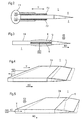
- FIGS. 4 and 5 also each show a perspective view of a lamella 7 or a separating element 8 of a headbox 1 (not shown) with a variable position L or contour K.
- the lamella 7 or the separating element 8 is local, sectional and / or according to the embodiment of FIG. 4 in the machine direction (MD) (arrow) or counter to the machine direction (MD) (arrow) by means of at least one schematically illustrated displacement device 15 according to the displacement arrows V. can be moved as a whole. This results in geometrical shifts, which are indicated as an example in dashed form.
Abstract
Description
Die Erfindung betrifft ein Verfahren zur Beeinflussung der Faserorientierung in einer aus mindestens einer Faserstoffsuspension hergestellten Faserstoffbahn, insbesondere einer Papier- oder Kartonbahn, wobei die Faserstoffsuspension durch eine Stoffauflaufdüse eines Stoffauflaufs einer Herstellungsmaschine, insbesondere einer Papier- oder Kartonmaschine, geführt wird, die zwei sich quer über die Maschinenbreite erstreckende Breitenwände (untere Düsenwand, obere Düsenwand) umfasst und die vorzugsweise mit mindestens einer Lamelle und/oder einem Trennelement versehen ist.The invention relates to a method for influencing the fiber orientation in a fibrous web produced from at least one fibrous suspension, in particular a paper or cardboard web, the fibrous suspension through a headbox nozzle of a headbox of a manufacturing machine, in particular a paper or board machine, the two are transversely Width walls extending across the machine width (lower nozzle wall, upper Nozzle wall) and preferably with at least one lamella and / or a separating element is provided.
Weiterhin betrifft die Erfindung einen Stoffauflauf gemäß dem Oberbegriff des Anspruchs
12 zur Durchführung des erfindungsgemäßen Verfahrens.Furthermore, the invention relates to a headbox according to the preamble of the
Es ist allgemein bekannt, einen Stoffauflauf zur Beeinflussung beziehungsweise
Einstellung der Faserorientierung (Grad der Ausrichtung der Fasern bei der
Faserbahnherstellung (Stoffauflauf-Sieb)) in einer aus mindestens einer Faserstoffsuspension
hergestellten Faserstoffbahn, insbesondere einer Papier- oder
Kartonbahn, zu benutzen, indem der örtliche Durchsatz an Faserstoffsuspension
durch den Turbulenzerzeuger des Stoffauflaufs verändert wird. Diese Veränderung
kann durch Verwendung verschiedener Einlaufbüchsen am Turbulenzerzeuger
und/oder anderer Rohrverengungen im Turbulenzerzeuger erfolgen.
Ein Problem dabei ist die schlechte Zugänglichkeit des Turbulenzerzeugers samt
dazugehörigen hydraulischen Vorrichtungen. It is generally known to use a headbox for influencing or adjusting the fiber orientation (degree of orientation of the fibers during fiber web production (headbox sieve)) in a fiber web made from at least one fiber suspension, in particular a paper or cardboard web, by using the local one Throughput of fiber suspension is changed by the turbulence generator of the headbox. This change can be made by using different inlet bushings on the turbulence generator and / or other pipe constrictions in the turbulence generator.
One problem is the poor accessibility of the turbulence generator and the associated hydraulic devices.
Auch ist bekannt, den Auslaufspalt eines Stoffauflaufs zwecks Beeinflussung
beziehungsweise Einstellung der Faserorientierung in einer aus mindestens einer
Faserstoffsuspension hergestellten Faserstoffbahn, insbesondere einer Papieroder
Kartonbahn, zu verändern, beispielsweise durch Anbringung und Betätigung
von Gewindespindeln zum Verschwenken oder Verbiegen der Stoffauflaufblende.
Derartige Einrichtungen sind aus den deutschen Offenlegungsschriften DE 29 42
966 A1 (PA03729 DE), DE 35 35 849 A1 (PA04265 DE) und DE 36 44 983 A1
(PA04356 DE) des Anmelders bekannt. Mittels der offenbarten Einrichtungen
kann der Durchsatz an Faserstoffsuspension über die Breite des Stoffauflaufs
hinweg örtlich verändert werden.
In nachteilhafter Weise wird jedoch gleichzeitig auch die Strömungsrichtung örtlich
beeinflusst und damit wiederum die Faserorientierung. Durch eine örtliche Verengung
des Auslaufspalts wird nämlich den Fasern an den Engstellen des Auslaufspalts
eine andere Strömungsrichtung erteilt als an anderen Stellen des Auslaufspalts.
Dies bedeutet, dass zwar das Flächengewicht durch diese so genannte
Verdrängungsregelung über die Breite des Stoffauflaufs beeinflusst werden kann,
dass sich gleichzeitig jedoch die gegebenenfalls gute Faserorientierung ändern
kann.It is also known to change the outlet gap of a headbox in order to influence or adjust the fiber orientation in a fibrous web made of at least one fibrous suspension, in particular a paper or cardboard web, for example by attaching and actuating threaded spindles to pivot or bend the headbox panel. Such devices are known from the German laid-open publications DE 29 42 966 A1 (PA03729 DE), DE 35 35 849 A1 (PA04265 DE) and DE 36 44 983 A1 (PA04356 DE) of the applicant. The throughput of fiber suspension can be changed locally across the width of the headbox by means of the disclosed devices.
Disadvantageously, however, the flow direction is also influenced locally, and with it the fiber orientation. Due to a local narrowing of the outlet gap, the fibers are given a different flow direction at the narrow points of the outlet gap than at other points of the outlet gap. This means that although the basis weight can be influenced by the so-called displacement control across the width of the headbox, the good fiber orientation, if any, can change at the same time.
Weiterhin ist aus der deutschen Offenlegungsschrift DE 199 08 973 A1 (PA10858
DE) des Anmelders bekannt, die mindestens eine in einer Stoffauflaufdüse angeordnete
Lamelle zwecks Beeinflussung beziehungsweise Einstellung der Faserorientierung
in einer aus mindestens einer Faserstoffsuspension hergestellten Faserstoffbahn,
insbesondere einer Papier- oder Kartonbahn, in Maschinenlaufrichtung
zu verschieben. Dabei kann die Lamelle in Maschinenquerrichtung sektioniert
und gegebenenfalls sektionsweise verstellbar ausgeführt sein.
Eine derartige Lamelle eignet sich zwar hervorragend zur Erfüllung der genannten
Aufgabe, sie ist jedoch teuer in der Herstellung und nicht unproblematisch im Betrieb
hinsichtlich Prozesssicherheit und Markierungsvermeidung in der herzustellenden
Faserstoffbahn. Furthermore, from the applicant's German published patent application DE 199 08 973 A1 (PA10858 DE) it is known that the at least one lamella arranged in a headbox nozzle in order to influence or adjust the fiber orientation in a fibrous web made from at least one fibrous suspension, in particular a paper or cardboard web To shift machine direction. The slat can be sectioned in the cross-machine direction and, if necessary, can be made adjustable in sections.
Although such a lamella is excellently suited for fulfilling the stated task, it is expensive to manufacture and not unproblematic in operation with regard to process reliability and avoidance of marking in the fibrous web to be produced.
Aus der deutschen Offenlegungsschrift DE 40 19 593 A1 (PA04598 DE) des Anmelders
ist ein Stoffauflauf für Papiermaschinen mit einem Verteiler zum Verteilen
einer zugeführten Faserstoffsuspension über die Arbeitsbreite der Papiermaschine,
einer eine Vielzahl von Löchern oder Kanälen aufweisenden Führungsvorrichtung
für die Faserstoffsuspension, einem maschinenbreiten Auslaufkanal
mit Auslaufspalt zum Verteilen der Faserstoffsuspension und ferner mit Mitteln
zum Einstellen der Stoffdichte der Stoffsuspension über die Arbeitsbreite hinweg
bekannt. Weiterhin ist der Stoffauflauf über seine Breite hinweg durch Trennwände
in Sektionen unterteilt, die einzelne Sektion weist wenigstens eine Zuleitung
zum Zuführen eines Teilstroms (Sektionsstroms) auf, der einzelnen Zuleitung
ist ein Mischer vorgeschaltet und der Mischer weist wenigstens zwei Anschlüsse
zum Heranführen von Suspensionsströmen mit vorgegebenen Betriebsparametern
(Durchsatz, Stoffdichte, Faserqualität) auf.
Zwar lassen sich durch einen derartigen Stoffauflauf die beiden Parameter Stoffdichte
und Faserorientierung auf praktikable und zuverlässige Weise unabhängig
voneinander beeinflussen, der Stoffauflauf selbst führt jedoch zu erhöhten Kosten,
insbesondere Anschaffungs- und Betriebskosten, und ist nur mit einem erhöhten
Aufwand an Regelungstechnik optimal betreibbar.From the applicant's German published patent application DE 40 19 593 A1 (PA04598 DE) is a headbox for paper machines with a distributor for distributing a supplied fiber suspension over the working width of the paper machine, a guide device for the fiber suspension having a plurality of holes or channels, and a machine-wide outlet channel known with outlet gap for distributing the fiber suspension and also with means for adjusting the consistency of the suspension over the working width. Furthermore, the headbox is divided into sections across its width by dividing walls, the individual section has at least one supply line for supplying a partial flow (section flow), the individual supply line is preceded by a mixer, and the mixer has at least two connections for introducing suspension flows with predetermined values Operating parameters (throughput, consistency, fiber quality).
Although such a headbox can influence the two parameters stock density and fiber orientation in a practical and reliable manner independently of one another, the headbox itself leads to increased costs, in particular acquisition and operating costs, and can only be operated optimally with increased expenditure on control technology.
Der Erfindung liegt die Aufgabe zugrunde, ein Verfahren der eingangs genannten
Art derart weiterzubilden, dass die Beeinflussung der Faserorientierung in einer
aus mindestens einer Faserstoffsuspension hergestellten Faserstoffbahn, insbesondere
einer Papier- oder Kartonbahn, in schneller, kostengünstiger und zuverlässiger
Weise bei einer hohen Runnability der Herstellungsmaschine, insbesondere
einer Papier- oder Kartonmaschine, ermöglicht wird.
Außerdem soll ein geeigneter Stoffauflauf zur Durchführung des erfindungsgemäßen
Verfahrens angegeben werden.The invention is based on the object of developing a method of the type mentioned at the outset such that influencing the fiber orientation in a fibrous web produced from at least one fibrous suspension, in particular a paper or cardboard web, in a fast, cost-effective and reliable manner with a high runnability of the production machine , in particular a paper or board machine, is made possible.
In addition, a suitable headbox for carrying out the method according to the invention should be specified.
Diese Aufgabe wird dadurch gelöst, dass die Faserorientierung durch mindestens eine Geometrieänderung im Bereich der Stoffauflaufdüse beeinflusst, vorzugsweise geregelt/gesteuert, wird. This problem is solved in that the fiber orientation by at least influences a geometry change in the area of the headbox nozzle, preferably regulated / controlled.
Durch diese relativ einfach zu bewerkstelligende Geometrieänderung im Bereich der Stoffauflaufdüse kann bei Erfüllung der vorgenannten Anforderungen direkt Einfluss auf den Verlauf der Faserorientierung in Maschinenquerrichtung (Cross Machine Direction (CD)) genommen werden. Die Geometrieveränderung kann dabei sowohl eine Volumenverkleinerung, eine Volumenverschiebung als auch eine Volumenvergrößerung bedeuten.Due to this relatively easy to do geometry change in the area the headbox nozzle can directly meet the above requirements Influence on the course of the fiber orientation in the cross machine direction (Cross Machine Direction (CD)). The geometry change can both a volume reduction, a volume shift as well mean an increase in volume.
Eine erste erfindungsgemäße Ausgestaltung sieht vor, dass die Geometrieänderung zumindest durch eine Änderung der Kontur der Stoffauflaufdüse erzeugt wird.A first embodiment according to the invention provides that the change in geometry at least by changing the contour of the headbox nozzle is produced.
Dabei wird vorzugsweise die Kontur der oberen Düsenwand und/oder der unteren Düsenwand in Maschinenlaufrichtung (Machine Direction (MD)) und/oder in Maschinenquerrichtung (CD) geändert.The contour of the upper nozzle wall and / or the lower one is preferred Nozzle wall in the machine direction (MD) and / or in Machine cross direction (CD) changed.
Hinsichtlich des Umfangs der Änderung der Kontur der Stoffauflaufdüse ist sowohl eine lokale, sektionale und/oder gesamtheitliche Änderung in Maschinenlaufrichtung (MD) und/oder in Maschinenquerrichtung (CD) möglich, wobei natürlich auch verschiedene Änderungsarten ihre Anwendung finden können.Regarding the amount of change in the contour of the headbox nozzle is both a local, sectional and / or holistic change in the machine direction (MD) and / or in the cross machine direction (CD) possible, of course different types of changes can also be used.
Eine zweite erfindungsgemäße Ausgestaltung sieht vor, dass die Geometrieänderung zumindest durch eine Änderung der Kontur und/oder der Lage der Lamelle und/oder des Trennelements erzeugt wird.A second embodiment of the invention provides that the change in geometry at least by changing the contour and / or the position of the lamella and / or the separating element is generated.
Dabei kann die Lamelle und/oder das Trennelement in Maschinenlaufrichtung (MD) oder entgegen der Maschinenlaufrichtung (MD) verschoben werden.The lamella and / or the separating element can be in the machine direction (MD) or against the machine direction (MD).
Hinsichtlich des Umfangs der Verschiebung der Lamelle und/oder des Trennelements ist sowohl eine lokale, sektionale und/oder gesamtheitliche Verschiebung in Maschinenlaufrichtung (MD) oder entgegen der Maschinenlaufrichtung (MD) möglich, wobei natürlich auch verschiedene Verschiebungsarten ihre Anwendung finden können. With regard to the extent of the displacement of the lamella and / or the separating element is both a local, sectional and / or holistic shift in Machine direction (MD) or against machine direction (MD) possible, of course, different types of displacement are also used can.
Weiterhin kann die Kontur der Lamelle und/oder des Trennelements in Maschinenlaufrichtung (MD) und/oder in Maschinenquerrichtung (CD) geändert werden.Furthermore, the contour of the lamella and / or the separating element can be in the machine running direction (MD) and / or in the cross machine direction (CD).
Hinsichtlich des Umfangs der Änderung der Kontur der Lamelle und/oder des Trennelements ist sowohl eine lokale, sektionale und/oder gesamtheitliche Änderung möglich, wobei natürlich auch verschiedene Änderungsarten ihre Anwendung finden können.With regard to the extent of the change in the contour of the lamella and / or Separator is both a local, sectional and / or holistic change possible, although of course different types of changes apply can find.
Unter strömungs- und regelungstechnischen Aspekten ist es vorteilhaft, wenn die Geometrieänderung bei gleichem Zulaufquerschnitt in die Stoffauflaufdüse und/oder bei parallelem oder annähernd parallelem Auslaufquerschnitt aus der Stoffauflaufdüse erfolgt.From a flow and control point of view it is advantageous if the Geometry change with the same inlet cross-section in the headbox nozzle and / or with a parallel or approximately parallel outlet cross-section from the Headbox nozzle takes place.
Eine sehr gute Beeinflussung der Faserorientierung in einer aus mindestens einer Faserstoffsuspension hergestellten Faserstoffbahn, insbesondere einer Papieroder Kartonbahn, wird erreicht, wenn die Geometrieänderung - in Strömungsrichtung der Faserstoffsuspension gesehen - im letzten Drittel oder auf den letzten 300 mm im Bereich der Stoffauflaufdüse erfolgt.A very good influence on the fiber orientation in one out of at least one Fibrous suspension produced fibrous web, in particular a paper or Cardboard web, is achieved when the geometry change - in the direction of flow the fiber suspension seen - in the last third or on the last 300 mm in the area of the headbox nozzle.
Ein geeigneter Stoffauflauf zur Durchführung des erfindungsgemäßen Verfahrens ist dadurch gekennzeichnet, dass mindestens eine Geometrie im Bereich der Stoffauflaufdüse zur Beeinflussung der Faserorientierung in der Faserstoffsuspension veränderbar, vorzugsweise regelbar/steuerbar, ist.A suitable headbox for carrying out the method according to the invention is characterized in that at least one geometry in the area of Headbox nozzle for influencing the fiber orientation in the fiber suspension is changeable, preferably controllable.
Eine erste erfindungsgemäße Ausgestaltung sieht vor, dass zumindest die Kontur der oberen Düsenwand und/oder der unteren Düsenwand der Stoffauflaufdüse in Maschinenlaufrichtung (MD) und/oder in Maschinenquerrichtung (CD) veränderbar ist. A first embodiment according to the invention provides that at least the contour the upper nozzle wall and / or the lower nozzle wall of the headbox nozzle in Machine direction (MD) and / or cross machine direction (CD) is changeable.
Dabei besteht die Düsenwand aus mindestens einer biegeweichen Platte, die mittels mindestens einer Verformungseinrichtung mechanisch und/oder elektromechanisch und/oder pneumatisch/hydraulisch insbesondere lokal, sektional und/oder gesamtheitlich in Maschinenlaufrichtung (MD) und/oder in Maschinenquerrichtung (CD) verformbar ist.The nozzle wall consists of at least one flexible plate that mechanically and / or electromechanically by means of at least one deformation device and / or pneumatic / hydraulic, especially locally, sectionally and / or as a whole in the machine direction (MD) and / or in the cross machine direction (CD) is deformable.
Eine zweite erfindungsgemäße Ausgestaltung sieht vor, dass zumindest die Lage und/oder die Kontur der Lamelle und/oder des Trennelements veränderbar ist.A second embodiment of the invention provides that at least the location and / or the contour of the lamella and / or the separating element can be changed.
Dabei kann die Lamelle oder das Trennelement in Maschinenlaufrichtung (MD) oder entgegen der Maschinenlaufrichtung (MD) mittels mindestens einer Verschiebeeinrichtung lokal, sektional und/oder gesamtheitlich in Maschinenlaufrichtung (MD) oder entgegen der Maschinenlaufrichtung (MD) verschiebbar sein. Die Lamelle kann gemäß dem Stand der Technik dabei sektioniert ausgeführt sein. The lamella or the separating element in the machine direction (MD) or against the machine direction (MD) by means of at least one displacement device locally, sectionally and / or holistically in the machine direction (MD) or against the machine direction (MD). According to the prior art, the lamella can be sectioned his.
Alternativ oder ergänzend kann die Kontur der Lamelle und/oder des Trennelements in Maschinenlaufrichtung (MD) und/oder in Maschinenquerrichtung (CD) insbesondere lokal, sektional und/oder gesamtheitlich veränderbar sein.Alternatively or additionally, the contour of the lamella and / or the separating element can be in machine direction (MD) and / or in machine direction (CD) in particular be changeable locally, sectionally and / or holistically.
Die Kontur der Lamelle und/oder des Trennelements ist vorzugsweise durch das Erzeugen mindestens einer leichten Verformung, insbesondere einer Verschiebung oder einer Wölbung, infolge mindestens einer Krafteinwirkung oder aufgrund mindestens einer aufgesetzten und verschiebbaren Abdeckung, insbesondere einer Platte und dergleichen, oder aufgrund verschiedener beaufschlagbarer Einbauten, insbesondere Druckkammern, Temperaturzonen, Piezo-Stellantrieben und dergleichen, veränderbar.The contour of the lamella and / or the separating element is preferably by Generate at least a slight deformation, in particular a displacement or a curvature, as a result of at least one force or due to at least one attached and slidable cover, in particular a plate and the like, or due to various pressurized internals, especially pressure chambers, temperature zones, piezo actuators and the like, changeable.
Um eine sehr gute Beeinflussung der Faserorientierung in einer aus mindestens einer Faserstoffsuspension hergestellten Faserstoffbahn, insbesondere einer Papier- oder Kartonbahn, zu erreichen, erfolgt die Geometrieänderung - in Strömungsrichtung der Faserstoffsuspension gesehen - im letzten Drittel oder auf den letzten 300 mm im Bereich der Stoffauflaufdüse.To have a very good influence on fiber orientation in at least one a fibrous web, in particular a paper or cardboard web, the geometry changes - in the direction of flow the fiber suspension seen - in the last third or on the last 300 mm in the area of the headbox nozzle.
Weitere Merkmale und Vorteile der Erfindung ergeben sich aus der nachfolgenden Beschreibung bevorzugter Ausführungsbeispiele unter Bezugnahme auf die Zeichnung.Further features and advantages of the invention result from the the following description of preferred exemplary embodiments under Reference to the drawing.
Es zeigen
Figuren 1 bis 5:- verschiedene Ausführungsformen des erfindungsgemäßen Stoffauflaufs in schematisierten Ansichten.
- Figures 1 to 5:
- different embodiments of the headbox according to the invention in schematic views.
Die Figur 1 zeigt eine schematisierte Seitenansicht eines Stoffauflaufs 1 einer
Herstellungsmaschine, insbesondere Papier- oder Kartonmaschine, zur Herstellung
einer Faserstoffbahn 2, insbesondere Papier- oder Kartonbahn, aus mindestens
einer Faserstoffsuspension 3, mit einer Stoffauflaufdüse 4, die zwei sich
quer über die Maschinenbreite erstreckende Breitenwände (untere Düsenwand 5,
obere Düsenwand 6) umfasst. Die Stoffauflaufdüse 4 ist bei bestimmten Papierund
Kartonsorten mit mindestens einer Lamelle 7 und bei mehrschichtigen Stoffaufläufen
mit mindestens einem Trennelement 8 versehen, wobei in der Figur 1
sowohl die Lamelle 7 als auch das Trennelement 8 als ein einzelnes Element beispielhaft
mittels einer gestrichelten Linie dargestellt sind. Selbstverständlich umfasst
der Stoffauflauf 1 noch eine Zufuhreinrichtung für die Faserstoffsuspension
3, insbesondere ein Querverteilrohr oder einen Rundverteiler, und mindestens
einen zwischen der Zufuhreinrichtung und der Stoffauflaufdüse 4 angeordneten
turbulenzerzeugenden Bereich, insbesondere ein Rohrgitter und/oder einen Turbulenzerzeuger,
wobei diese Baugruppen nicht explizit dargestellt, dem Fachmann
jedoch bekannt sind.FIG. 1 shows a schematic side view of a
Es ist nunmehr mindestens eine Geometrie im Bereich der Stoffauflaufdüse 4 zur
Beeinflussung der Faserorientierung in der Faserstoffsuspension 3 veränderbar,
vorzugsweise regelbar/steuerbar. Im Hinblick auf die Ermöglichung dieser Geometrieänderung
ist zumindest die Kontur K der oberen Düsenwand 5 und/oder der
unteren Düsenwand 6 der Stoffauflaufdüse 4 in Maschinenlaufrichtung (MD)
(Pfeil) und/oder in Maschinenquerrichtung (CD) (Pfeil) veränderbar. In Figur 1 besteht
beispielsweise jede Düsenwand 5, 6 aus mindestens einer biegeweichen
Platte 9, die mittels mindestens einer Verformungseinrichtung 10 mechanisch
und/oder elektromechanisch und/oder pneumatisch/hydraulisch verformbar ist,
wobei die Richtungen der Verformungen durch Pfeile dargestellt sind. Die jeweilige
Verformung kann lokal, sektional und/oder gesamtheitlich bewirkt werden. Die
mechanische Verformungseinrichtung 10 kann beispielsweise eine an sich bekannte
Spindeleinheit mit jeweiligem Antrieb oder mindestens ein Exzenterantrieb
sein, die elektromechanische Verformungseinrichtung 10 kann beispielsweise ein
Stellmotor sein und die pneumatische/hydraulische Verformungseinrichtung 10
kann beispielsweise mindestens eine Zylindereinheit oder ein Druckpolster sein.
Die jeweilige Verformungseinrichtung 10 ist in Figur 1 lediglich schematisiert dargestellt.There is now at least one geometry in the area of the
Die Geometrieänderung erfolgt - in Strömungsrichtung S (Pfeil) der Faserstoffsuspension
3 gesehen - im letzten Drittel oder auf den letzten 300 mm im Bereich der
Stoffauflaufdüse 4. Dabei führen minimale Änderungen im Bereich von wenigen
Zehntel Millimetern im Düsenquerschnitt zu signifikanten Änderungen der Faserorientierung.
Zum Beispiel können örtlich 0,1 mm Dicke in Maschinenquerrichtung
(CD) (Pfeil) eine Änderung des Faserorientierungswinkels von bis zu 2 Grad erzeugen.The geometry changes - in the flow direction S (arrow) of the
Die beiden Figuren 1a und 1b zeigen in schematisierter Darstellung je eine Düsenwand
5, 6 mit eingelegter biegeweicher Platte 9, die von einer nicht explizit
dargestellten Verformungseinrichtung 10 entsprechend verformt wird. Die Verformung
kann dabei sektioniert oder in Maschinenquerrichtung (CD) (Pfeil)
mehrmals sektioniert erfolgen und die biegeweiche Platte 9 kann auf ihrer
Abströmseite 11 mindestens einen Stufensprung 12 aufweisen.The two FIGS. 1a and 1b each show a nozzle wall in a
Die Figur 2 zeigt eine schematisierte Seitenansicht einer Lamelle 7 oder eines
Trennelements 8 eines Stoffauflaufs 1 einer Herstellungsmaschine, insbesondere
Papier- oder Kartonmaschine.
Dabei ist vorgesehen, dass mindestens eine Geometrie im Bereich der Stoffauflaufdüse
4 zur Beeinflussung der Faserorientierung 3 in der Faserstoffsuspension
veränderbar, vorzugsweise regelbar/steuerbar, ist.
Im Hinblick auf die Ermöglichung dieser Geometrieänderung ist die Lamelle 7
oder das Trennelement in bekannter Weise in einer Halterung 7.1 vorzugsweise
schwenkbar gelagert. Die Lamelle 7 oder das Trennelement 8 selbst ist vorzugsweise
beidseitig mit einer verschiebbaren Abdeckung 7.2 (Verschiebepfeil V) versehen.
Die verschiebbare Abdeckung 7.2 kann beispielsweise als mindestens
zwei aufgesetzte Platten ausgeführt sein, wobei die Platten sektioniert sein können
und verschiedene Größen, Höhen und Oberflächenbeschaffenheiten aufweisen
können. Durch diese Verschiebung der Abdeckung 7.2 mittels mindestens
einer, vorzugsweise zweier Verschiebeeinrichtungen 15 wird also eine Geometrieänderung
im Bereich der Stoffauflaufdüse 4 herbeigeführt.FIG. 2 shows a schematic side view of a lamella 7 or a separating element 8 of a
It is provided that at least one geometry in the area of the
In order to enable this change in geometry, the lamella 7 or the separating element is preferably pivotably mounted in a holder 7.1 in a known manner. The lamella 7 or the separating element 8 itself is preferably provided on both sides with a displaceable cover 7.2 (displacement arrow V). The displaceable cover 7.2 can be designed, for example, as at least two attached plates, wherein the plates can be sectioned and can have different sizes, heights and surface textures. This displacement of the cover 7.2 by means of at least one, preferably two
Die Figur 3 zeigt eine schematisierte Seitenansicht einer Lamelle 7 oder eines
Trennelements 8 eines Stoffauflaufs 1 mit veränderbarer Kontur K. Die Kontur K
ist dabei mittels verschiedener beaufschlagbarer Einbauten 13, insbesondere
Druckkammern, Temperaturzonen, Piezo-Stellantrieben und dergleichen, veränderbar,
wobei diese Einbauten 13 und deren Betriebseinheiten (Antriebseinheit,
Regel-/Steuereinheit und dergleichen) 14 lediglich schematisch dargestellt sind.
Diese Einbauten können sowohl in Maschinenlaufrichtung (MD) (Pfeil) als auch in
Maschinenquerrichtung (CD) (Pfeil) lokal, sektional oder gesamtheitlich sektioniert
sein.FIG. 3 shows a schematic side view of a lamella 7 or one
Separating element 8 of a
Auch die Figuren 4 und 5 zeigen in perspektivischer Ansicht je eine Lamelle 7
oder ein Trennelement 8 eines nicht dargestellten Stoffauflaufs 1 mit veränderbarer
Lage L beziehungsweise Kontur K.
Dabei ist die Lamelle 7 oder das Trennelement 8 gemäß der Ausführung der Figur
4 in Maschinenlaufrichtung (MD) (Pfeil) oder entgegen der Maschinenlaufrichtung
(MD) (Pfeil) mittels mindestens einer schematisiert dargestellten Verschiebeeinrichtung
15 gemäß der Verschiebepfeile V lokal, sektional und/oder gesamtheitlich
verschiebbar. Es ergeben sich damit Geometrieverschiebungen, die beispielhaft
in gestrichelter Form angedeutet sind.
Auch ist gemäß der Ausführung der Figur 5 die Kontur K der Lamelle 7 oder des
Trennelements 8 in Maschinenlaufrichtung (MD) (Pfeil) und/oder in Maschinenquerrichtung
(CD) (Pfeil) mittels mindestens einer schematisiert dargestellten Verschiebeeinrichtung
15 gemäß des Verschiebepfeils V lokal, sektional und/oder
gesamtheitlich veränderbar. Es ist deutlich erkennbar, dass die Kontur K der Lamelle
7 und/oder des Trennelements 8 durch das Erzeugen mindestens einer
leichten Verformung (gestrichelte Linie), insbesondere einer Verschiebung oder
einer Wölbung, infolge mindestens einer Krafteinwirkung KE (Pfeil) veränderbar
ist.FIGS. 4 and 5 also each show a perspective view of a lamella 7 or a separating element 8 of a headbox 1 (not shown) with a variable position L or contour K.
The lamella 7 or the separating element 8 is local, sectional and / or according to the embodiment of FIG. 4 in the machine direction (MD) (arrow) or counter to the machine direction (MD) (arrow) by means of at least one schematically illustrated
5, the contour K of the lamella 7 or the separating element 8 is local in the machine direction (MD) (arrow) and / or in the cross machine direction (CD) (arrow) by means of at least one schematically illustrated
Die in den Figuren 1 bis 5 dargestellten Möglichkeiten zur bereits beschriebenen Beeinflussung der Faserorientierung in einer bekannten Faserstoffbahn aufgrund einer Geometrieänderung im Bereich der Stoffauflaufdüse können selbstverständlich mit mindestens einer bekannten Regel- und/oder Steuereinrichtung geregelt beziehungsweise gesteuert werden. Die jeweilige Einrichtung kann dabei an ein Prozessleitsystem angeschlossen sein, welches wiederum Teil einer übergeordneten Einheit sein kann.The options shown in Figures 1 to 5 for the already described Influencing the fiber orientation in a known fibrous web due to a change in geometry in the area of the headbox nozzle can of course regulated with at least one known regulating and / or control device or controlled. The respective facility can be a Process control system connected, which in turn is part of a higher-level Unity can be.
Der erfindungsgemäße Stoffauflauf 1 eignet sich in hervorragender Weise zur
Durchführung des genannten erfindungsgemäßen Verfahrens zur Beeinflussung
der Faserorientierung in einer aus mindestens einer Faserstoffsuspension hergestellten
Faserstoffbahn, insbesondere einer Papier- oder Kartonbahn.The
Zusammenfassend ist festzuhalten, dass durch die Erfindung sowohl ein Verfahren als auch ein Stoffauflauf der eingangs genannten Art geschaffen wird, welche die Beeinflussung der Faserorientierung in einer aus mindestens einer Faserstoffsuspension hergestellten Faserstoffbahn, insbesondere einer Papier- oder Kartonbahn, in schneller, kostengünstiger und zuverlässiger Weise bei einer hohen Runnability der Herstellungsmaschine, insbesondere einer Papier- oder Kartonmaschine, ermöglichen. In summary, it should be noted that the invention is both a method as well as a headbox of the type mentioned is created, which influencing the fiber orientation in one of at least one fiber suspension manufactured fibrous web, in particular a paper or Cardboard web, in a fast, inexpensive and reliable way at a high Runnability of the manufacturing machine, especially a paper or board machine, enable.
- 11
- Stoffauflaufheadbox
- 22
- FaserstoffbahnFibrous web
- 33
- FaserstoffsuspensionFibrous suspension
- 44
- Stoffauflaufdüseheadbox
- 55
- Untere Düsenwand (Breitenwand)Lower nozzle wall (width wall)
- 66
- Obere Düsenwand (Breitenwand)Upper nozzle wall (width wall)
- 77
- Lamellelamella
- 7.17.1
- Halterungbracket
- 7.27.2
- Abdeckungcover
- 88th
- Trennelementseparating element
- 99
- Platteplate
- 1010
- Verformungseinrichtungdeforming means
- 1111
- Abströmseiteoutflow
- 1212
- Stufensprungincrement
- 1313
- Einbautenfixtures
- 1414
- Betriebseinheitoperating unit
- 1515
- Verschiebeeinrichtungshifter
- CDCD
- Maschinenquerrichtung (Pfeil)Cross machine direction (arrow)
- KK
- Konturcontour
- LL
- Lagelocation
- KEKE
- Krafteinwirkung (Pfeil)Application of force (arrow)
- MDMD
- Maschinenlaufrichtung (Pfeil)Machine direction (arrow)
- SS
- Strömungsrichtung (Pfeil)Flow direction (arrow)
- VV
- Verschiebepfeildisplacement arrow
Claims (24)
dadurch gekennzeichnet, dass die Faserorientierung durch mindestens eine Geometrieänderung im Bereich der Stoffauflaufdüse (4) beeinflusst, vorzugsweise geregelt/gesteuert, wird.Method for influencing the fiber orientation in a fibrous web (2) produced from at least one fibrous suspension (3), in particular a paper or cardboard web, the fibrous suspension (3) through a headbox nozzle (4) of a headbox (1) of a manufacturing machine, in particular a paper - Or cardboard machine is guided, which comprises two width walls extending across the machine width (lower nozzle wall (5), upper nozzle wall (6)) and which is preferably provided with at least one lamella (7) and / or a separating element (8) .
characterized in that the fiber orientation is influenced, preferably regulated, by at least one change in geometry in the area of the headbox nozzle (4).
dadurch gekennzeichnet, dass die Geometrieänderung zumindest durch eine Änderung der Kontur (K) der Stoffauflaufdüse (4) erzeugt wird. Method according to claim 1,
characterized in that the change in geometry is generated at least by changing the contour (K) of the headbox nozzle (4).
dadurch gekennzeichnet, dass die Kontur (K) der unteren Düsenwand (5) und/oder der oberen Düsenwand (6) in Maschinenlaufrichtung (MD) und/oder in Maschinenquerrichtung (CD) geändert wird.Method according to claim 2,
characterized in that the contour (K) of the lower nozzle wall (5) and / or the upper nozzle wall (6) is changed in the machine direction (MD) and / or in the cross-machine direction (CD).
dadurch gekennzeichnet, dass die Kontur (K) der Stoffauflaufdüse (4) lokal, sektional und/oder gesamtheitlich in Maschinenlaufrichtung (MD) und/oder in Maschinenquerrichtung (CD) geändert wird.Method according to claim 2 or 3,
characterized in that the contour (K) of the headbox nozzle (4) is changed locally, sectionally and / or in its entirety in the machine direction (MD) and / or in the machine direction (CD).
dadurch gekennzeichnet, dass die Geometrieänderung zumindest durch eine Änderung der Lage (L) und/oder der Kontur (K) der Lamelle (7) und/oder des Trennelements (8) erzeugt wird.Method according to claim 1,
characterized in that the change in geometry is generated at least by changing the position (L) and / or the contour (K) of the lamella (7) and / or the separating element (8).
dadurch gekennzeichnet, dass die Lamelle (7) und/oder das Trennelement (8) in Maschinenlaufrichtung (MD) oder entgegen der Maschinenlaufrichtung (MD) verschoben wird beziehungsweise werden.Method according to claim 5,
characterized in that the lamella (7) and / or the separating element (8) is or are displaced in the machine direction (MD) or counter to the machine direction (MD).
dadurch gekennzeichnet, dass die Lamelle (7) und/oder das Trennelement (8) lokal, sektional und/oder gesamtheitlich in Maschinenlaufrichtung (MD) oder entgegen der Maschinenlaufrichtung (MD) verschoben wird beziehungsweise werden.Method according to claim 6,
characterized in that the lamella (7) and / or the separating element (8) is or are displaced locally, sectionally and / or as a whole in the machine direction (MD) or counter to the machine direction (MD).
dadurch gekennzeichnet, dass die Kontur (K) der Lamelle (7) und/oder des Trennelements (8) in Maschinenlaufrichtung (MD) und/oder in Maschinenquerrichtung (CD) geändert wird.Method according to claim 5,
characterized in that the contour (K) of the lamella (7) and / or the separating element (8) is changed in the machine direction (MD) and / or in the machine direction (CD).
dadurch gekennzeichnet, dass die Kontur (K) der Lamelle (7) und/oder des Trennelements (8) lokal, sektional und/oder gesamtheitlich in Maschinenlaufrichtung (MD) und/oder in Maschinenquerrichtung (CD) geändert wird.Method according to claim 5 or 8,
characterized in that the contour (K) of the lamella (7) and / or the separating element (8) is changed locally, sectionally and / or in its entirety in the machine direction (MD) and / or in the machine direction (CD).
dadurch gekennzeichnet, dass die Geometrieänderung - in Strömungsrichtung (S) der Faserstoffsuspension (3) gesehen - im letzten Drittel oder auf den letzten 300 mm im Bereich der Stoffauflaufdüse (4) erfolgt.Method according to one of the preceding claims,
characterized in that the change in geometry - seen in the flow direction (S) of the fiber suspension (3) - takes place in the last third or over the last 300 mm in the area of the headbox nozzle (4).
dadurch gekennzeichnet, dass die Geometrieänderung bei gleichem Zulaufquerschnitt in die Stoffauflaufdüse (4) und/oder bei parallelem oder annähernd parallelem Auslaufquerschnitt aus der Stoffauflaufdüse (4) erfolgt.Method according to one of the preceding claims,
characterized in that the geometry change takes place with the same inlet cross section into the headbox nozzle (4) and / or with a parallel or approximately parallel outlet cross section from the headbox nozzle (4).
dadurch gekennzeichnet, dass mindestens eine Geometrie im Bereich der Stoffauflaufdüse (4) zur Beeinflussung der Faserorientierung in der Faserstoffsuspension (3) veränderbar, vorzugsweise regelbar/steuerbar, ist.Headbox (1) of a manufacturing machine, in particular paper or cardboard machine, for producing a fibrous web (2), in particular paper or cardboard web, from at least one fibrous suspension (3), with a headbox nozzle (4), the two extending across the machine width Width walls (lower nozzle wall (5), upper nozzle wall (6)) and which is preferably provided with at least one lamella (7) and / or a separating element (8),
characterized in that at least one geometry in the area of the headbox nozzle (4) can be changed, preferably regulated / controlled, to influence the fiber orientation in the fiber suspension (3).
dadurch gekennzeichnet, dass zumindest die Kontur (K) der unteren Düsenwand (5) und/oder der oberen Düsenwand (6) der Stoffauflaufdüse (4) in Maschinenlaufrichtung (MD) und/oder in Maschinenquerrichtung (CD) veränderbar istHeadbox (1) according to claim 12,
characterized in that at least the contour (K) of the lower nozzle wall (5) and / or the upper nozzle wall (6) of the headbox nozzle (4) can be changed in the machine direction (MD) and / or in the machine direction (CD)
dadurch gekennzeichnet, dass die Düsenwand (5, 6) aus mindestens einer biegeweichen Platte (9) besteht, die mittels mindestens einer Verformungseinrichtung (10) mechanisch und/oder elektromechanisch und/oder pneumatisch/hydraulisch verformbar ist.Headbox (1) according to claim 13,
characterized in that the nozzle wall (5, 6) consists of at least one flexible plate (9) which can be deformed mechanically and / or electromechanically and / or pneumatically / hydraulically by means of at least one deformation device (10).
dadurch gekennzeichnet, dass die Düsenwand (5, 6) lokal, sektional und/oder gesamtheitlich in Maschinenlaufrichtung (MD) und/oder in Maschinenquerrichtung (CD) verformbar ist.Headbox (1) according to claim 13 or 14,
characterized in that the nozzle wall (5, 6) can be deformed locally, sectionally and / or holistically in the machine direction (MD) and / or in the machine direction (CD).
dadurch gekennzeichnet, dass zumindest die Lage (L) und/oder die Kontur (K) der Lamelle (7) und/oder des Trennelements (8) veränderbar ist.Headbox (1) according to claim 12,
characterized in that at least the position (L) and / or the contour (K) of the lamella (7) and / or the separating element (8) can be changed.
dadurch gekennzeichnet, dass die Lamelle (7) und/oder das Trennelement (8) in Maschinenlaufrichtung (MD) oder entgegen der Maschinenlaufrichtung (MD) mittels mindestens einer Verschiebeeinrichtung (15) verschiebbar ist beziehungsweise sind.Headbox (1) according to claim 16,
characterized in that the lamella (7) and / or the separating element (8) can be displaced in the machine direction (MD) or counter to the machine direction (MD) by means of at least one displacement device (15).
dadurch gekennzeichnet, dass die Lamelle (7) und/oder das Trennelement (8) lokal, sektional und/oder gesamtheitlich in Maschinenlaufrichtung (MD) oder entgegen der Maschinenlaufrichtung (MD) mittels mindestens einer Verschiebeeinrichtung (15) verschiebbar ist beziehungsweise sind.Headbox (1) according to claim 17,
characterized in that the lamella (7) and / or the separating element (8) can be displaced locally, sectionally and / or holistically in the machine direction (MD) or counter to the machine direction (MD) by means of at least one displacement device (15).
dadurch gekennzeichnet, dass die Kontur (K) der Lamelle (7) und/oder des Trennelements (8) in Maschinenlaufrichtung (MD) und/oder in Maschinenquerrichtung (CD) veränderbar ist. Headbox (1) according to claim 16,
characterized in that the contour (K) of the lamella (7) and / or the separating element (8) can be changed in the machine direction (MD) and / or in the machine direction (CD).
dadurch gekennzeichnet, dass die Kontur (K) der Lamelle (7) und/oder des Trennelements (8) lokal, sektional und/oder gesamtheitlich in Maschinenlaufrichtung (MD) und/oder in Maschinenquerrichtung (CD) veränderbar ist.Headbox (1) according to claim 19,
characterized in that the contour (K) of the lamella (7) and / or the separating element (8) can be changed locally, sectionally and / or in its entirety in the machine direction (MD) and / or in the machine direction (CD).
dadurch gekennzeichnet, dass die Kontur (K) der Lamelle (7) und/oder des Trennelements (8) durch das Erzeugen mindestens einer leichten Verformung, insbesondere einer Verschiebung oder einer Wölbung, infolge mindestens einer Krafteinwirkung veränderbar ist.Headbox (1) according to claim 19 or 20,
characterized in that the contour (K) of the lamella (7) and / or the separating element (8) can be changed by generating at least a slight deformation, in particular a displacement or a curvature, as a result of at least one action of force.
dadurch gekennzeichnet, dass die Kontur (K) der Lamelle (7) und/oder des Trennelements (8) aufgrund verschiedener beaufschlagbarer Einbauten, insbesondere Druckkammern, Temperaturzonen, Piezo-Stellantrieben und dergleichen, veränderbar ist.Headbox (1) according to claim 19 or 20,
characterized in that the contour (K) of the lamella (7) and / or the separating element (8) can be changed on account of various internals which can be acted upon, in particular pressure chambers, temperature zones, piezo actuators and the like.
dadurch gekennzeichnet, dass die Kontur (K) der Lamelle (7) und/oder des Trennelements (8) aufgrund mindestens einer aufgesetzten und verschiebbaren Abdeckung (7.2), insbesondere einer Platte und dergleichen, veränderbar ist.Headbox (1) according to claim 19 or 20,
characterized in that the contour (K) of the lamella (7) and / or of the separating element (8) can be changed on the basis of at least one cover which can be moved and is displaceable (7.2), in particular a plate and the like.
dadurch gekennzeichnet, dass die Geometrieänderung - in Strömungsrichtung (S) der Faserstoffsuspension (3) gesehen - im letzten Drittel oder auf den letzten 300 mm im Bereich der Stoffauflaufdüse (4) erfolgt.Headbox (1) according to one of claims 12 to 23,
characterized in that the change in geometry - seen in the flow direction (S) of the fiber suspension (3) - takes place in the last third or over the last 300 mm in the area of the headbox nozzle (4).
Applications Claiming Priority (2)
| Application Number | Priority Date | Filing Date | Title |
|---|---|---|---|
| DE10249820 | 2002-10-25 | ||
| DE2002149820 DE10249820A1 (en) | 2002-10-25 | 2002-10-25 | Paper suspension fibers orientated by headbox horizontal jet with variable geometry upper and lower panels altered by pressure, temperature or piezo-effect |
Publications (1)
| Publication Number | Publication Date |
|---|---|
| EP1445374A1 true EP1445374A1 (en) | 2004-08-11 |
Family
ID=32103021
Family Applications (1)
| Application Number | Title | Priority Date | Filing Date |
|---|---|---|---|
| EP03102714A Ceased EP1445374A1 (en) | 2002-10-25 | 2003-09-05 | Method for influencing fibre orientation and headbox suitable therefor |
Country Status (2)
| Country | Link |
|---|---|
| EP (1) | EP1445374A1 (en) |
| DE (1) | DE10249820A1 (en) |
Families Citing this family (3)
| Publication number | Priority date | Publication date | Assignee | Title |
|---|---|---|---|---|
| FI20050315A (en) * | 2005-03-24 | 2006-09-25 | Metso Paper Inc | Method for controlling vibration of the lip of the headbox lip and lamella of the lip of the headbox |
| DE102005060715A1 (en) * | 2005-12-19 | 2007-06-21 | Siemens Ag | Paper machine with one or more valve devices |
| FI120654B (en) | 2006-03-22 | 2010-01-15 | Metso Paper Inc | Method in connection with an outlet box of a paper or cardboard machine and slats in an outlet box of a paper or cardboard machine |
Citations (4)
| Publication number | Priority date | Publication date | Assignee | Title |
|---|---|---|---|---|
| DE1135744B (en) * | 1957-01-01 | 1962-08-30 | Albert E Reed & Company Ltd | An exit gap for the headbox of a paper machine consisting of the upper and lower lip |
| US4133713A (en) * | 1977-10-11 | 1979-01-09 | The Procter & Gamble Company | Microturbulence generator for papermachine headbox |
| DE19747295A1 (en) * | 1997-07-25 | 1999-01-28 | Voith Sulzer Papiermasch Gmbh | Paper=making machine headbox helps sectional control of web formation |
| DE19846614A1 (en) * | 1998-10-09 | 2000-04-13 | Voith Sulzer Papiertech Patent | Design of headbox nozzle in papermaking machine recognizes that high static pressure of initial suspension acceleration followed by lower pressure in parallel flow and offers material- and weight optimization opportunity |
Family Cites Families (4)
| Publication number | Priority date | Publication date | Assignee | Title |
|---|---|---|---|---|
| DE3321406A1 (en) * | 1983-06-09 | 1984-12-13 | Escher Wyss Gmbh, 7980 Ravensburg | FABRIC DRIVE FOR A PAPER MACHINE |
| DD265186A1 (en) * | 1987-09-09 | 1989-02-22 | Freiberg Papier Maschwerke | STOFFAUFLAUF FOR PAPER MACHINES OR THE SIMILAR |
| DE4018054A1 (en) * | 1990-06-06 | 1991-12-12 | Voith Gmbh J M | EXPANDING BODY, ESPECIALLY FOR THE MATERIAL OUTLET OF A PAPER MACHINE |
| DE19908973A1 (en) * | 1999-03-02 | 2000-09-07 | Voith Sulzer Papiertech Patent | Process for regulating the tear length ratio of a paper web and paper machine produced |
-
2002
- 2002-10-25 DE DE2002149820 patent/DE10249820A1/en not_active Withdrawn
-
2003
- 2003-09-05 EP EP03102714A patent/EP1445374A1/en not_active Ceased
Patent Citations (4)
| Publication number | Priority date | Publication date | Assignee | Title |
|---|---|---|---|---|
| DE1135744B (en) * | 1957-01-01 | 1962-08-30 | Albert E Reed & Company Ltd | An exit gap for the headbox of a paper machine consisting of the upper and lower lip |
| US4133713A (en) * | 1977-10-11 | 1979-01-09 | The Procter & Gamble Company | Microturbulence generator for papermachine headbox |
| DE19747295A1 (en) * | 1997-07-25 | 1999-01-28 | Voith Sulzer Papiermasch Gmbh | Paper=making machine headbox helps sectional control of web formation |
| DE19846614A1 (en) * | 1998-10-09 | 2000-04-13 | Voith Sulzer Papiertech Patent | Design of headbox nozzle in papermaking machine recognizes that high static pressure of initial suspension acceleration followed by lower pressure in parallel flow and offers material- and weight optimization opportunity |
Also Published As
| Publication number | Publication date |
|---|---|
| DE10249820A1 (en) | 2004-05-13 |
Similar Documents
| Publication | Publication Date | Title |
|---|---|---|
| EP0789107B1 (en) | Headbox for papermaking machines | |
| DE3741603C2 (en) | ||
| EP1645684B1 (en) | Method and device for regulating the transverse grammage profile of a fibrous web | |
| WO2010069651A1 (en) | Headbox for a machine for producing a fibrous web | |
| WO1989011561A1 (en) | Headbox for paper-making machines | |
| DE10234559A1 (en) | Papermaking machine for low-volume paper or carton has vortex generator block made of a single integral plastic unit with jets discharging to sieve belt | |
| EP1445374A1 (en) | Method for influencing fibre orientation and headbox suitable therefor | |
| EP1033437A2 (en) | Method and device for controlling the breaking length ratio in a paper machine | |
| EP1770206B1 (en) | Method and forming system for producing a fibrous web | |
| DE4237310C2 (en) | Headbox with device for adjusting the fiber orientation | |
| EP1489224A1 (en) | Headbox | |
| EP2531647B1 (en) | Headbox and sheet-forming unit comprising a headbox | |
| EP0978587B1 (en) | Process for setting a uniform transverse profile for a paper web | |
| DE4234940A1 (en) | Controlling density of slurry at paper machine head-box - using devices to regulate the amt. of fibre in suspension before being deposited on the wire | |
| EP2585633B1 (en) | Headbox for a machine for producing a fibre-material web | |
| EP1934399A1 (en) | Method for producing a fibrous web and twin-wire former for carrying out said method | |
| DE102009029576A1 (en) | Headbox for use in fibrous material suspension of machine for producing e.g. paper web, has turbulence generating unit arranged in inner space of headbox nozzle during formation of nozzle intermediate channel and short nozzle | |
| DE10230301A1 (en) | Paper-making fibre dispensing jets, have vortex generators causing pressure drop | |
| DE10208610B4 (en) | Method for distributing a pulp suspension in the headbox of a paper or board machine and headbox | |
| DE19715790A1 (en) | Suspension distributor for e.g. papermaking machine, delivering over its full width | |
| DE10102087A1 (en) | Adjustment of fiber orientation in pulp suspension takes place in turbulence generator tube where step changes in cross section have variable separation for flow control | |
| DE2830046A1 (en) | PROCESS AND DEVICE FOR REGULATING THE CROSS PROFILE OF THE FIBER WEB IN A PAPER MACHINE | |
| DE102021105475A1 (en) | Adjustable lateral distribution for a headbox | |
| DE19718034A1 (en) | Stock inlet | |
| EP1342835B1 (en) | Headbox |
Legal Events
| Date | Code | Title | Description |
|---|---|---|---|
| PUAI | Public reference made under article 153(3) epc to a published international application that has entered the european phase |
Free format text: ORIGINAL CODE: 0009012 |
|
| AK | Designated contracting states |
Kind code of ref document: A1 Designated state(s): AT BE BG CH CY CZ DE DK EE ES FI FR GB GR HU IE IT LI LU MC NL PT RO SE SI SK TR |
|
| AX | Request for extension of the european patent |
Extension state: AL LT LV MK |
|
| 17P | Request for examination filed |
Effective date: 20050211 |
|
| AKX | Designation fees paid |
Designated state(s): AT BE BG CH CY CZ DE DK EE ES FI FR GB GR HU IE IT LI LU MC NL PT RO SE SI SK TR |
|
| RAP1 | Party data changed (applicant data changed or rights of an application transferred) |
Owner name: VOITH PATENT GMBH |
|
| STAA | Information on the status of an ep patent application or granted ep patent |
Free format text: STATUS: THE APPLICATION HAS BEEN REFUSED |
|
| 18R | Application refused |
Effective date: 20061105 |