EP1445343A1 - Method and system for thermal spraying - Google Patents
Method and system for thermal spraying Download PDFInfo
- Publication number
- EP1445343A1 EP1445343A1 EP02801574A EP02801574A EP1445343A1 EP 1445343 A1 EP1445343 A1 EP 1445343A1 EP 02801574 A EP02801574 A EP 02801574A EP 02801574 A EP02801574 A EP 02801574A EP 1445343 A1 EP1445343 A1 EP 1445343A1
- Authority
- EP
- European Patent Office
- Prior art keywords
- thermal spraying
- spraying powder
- connecting conduit
- powder
- intake end
- Prior art date
- Legal status (The legal status is an assumption and is not a legal conclusion. Google has not performed a legal analysis and makes no representation as to the accuracy of the status listed.)
- Withdrawn
Links
- 238000007751 thermal spraying Methods 0.000 title claims abstract description 348
- 238000000034 method Methods 0.000 title claims abstract description 23
- 239000000843 powder Substances 0.000 claims abstract description 190
- 238000002485 combustion reaction Methods 0.000 claims abstract description 50
- 230000008018 melting Effects 0.000 claims abstract description 31
- 238000002844 melting Methods 0.000 claims abstract description 31
- 239000000567 combustion gas Substances 0.000 claims description 21
- 238000011144 upstream manufacturing Methods 0.000 claims description 5
- 230000001174 ascending effect Effects 0.000 claims description 3
- 238000007599 discharging Methods 0.000 claims description 3
- 238000005507 spraying Methods 0.000 description 41
- 239000000463 material Substances 0.000 description 17
- 230000003746 surface roughness Effects 0.000 description 17
- QVGXLLKOCUKJST-UHFFFAOYSA-N atomic oxygen Chemical compound [O] QVGXLLKOCUKJST-UHFFFAOYSA-N 0.000 description 15
- 239000001301 oxygen Substances 0.000 description 15
- 229910052760 oxygen Inorganic materials 0.000 description 15
- 238000010285 flame spraying Methods 0.000 description 14
- 239000000446 fuel Substances 0.000 description 12
- 239000002826 coolant Substances 0.000 description 11
- 230000000052 comparative effect Effects 0.000 description 10
- 239000007789 gas Substances 0.000 description 8
- 238000011156 evaluation Methods 0.000 description 6
- 239000012159 carrier gas Substances 0.000 description 5
- 230000015572 biosynthetic process Effects 0.000 description 4
- 239000011248 coating agent Substances 0.000 description 4
- 238000000576 coating method Methods 0.000 description 4
- XLYOFNOQVPJJNP-UHFFFAOYSA-N water Substances O XLYOFNOQVPJJNP-UHFFFAOYSA-N 0.000 description 4
- 238000000151 deposition Methods 0.000 description 3
- 239000000203 mixture Substances 0.000 description 3
- 239000002245 particle Substances 0.000 description 3
- 238000005498 polishing Methods 0.000 description 3
- QQONPFPTGQHPMA-UHFFFAOYSA-N propylene Natural products CC=C QQONPFPTGQHPMA-UHFFFAOYSA-N 0.000 description 3
- 125000004805 propylene group Chemical group [H]C([H])([H])C([H])([*:1])C([H])([H])[*:2] 0.000 description 3
- XKRFYHLGVUSROY-UHFFFAOYSA-N Argon Chemical compound [Ar] XKRFYHLGVUSROY-UHFFFAOYSA-N 0.000 description 2
- 239000006243 Fine Thermal Substances 0.000 description 2
- 230000008021 deposition Effects 0.000 description 2
- 229910003460 diamond Inorganic materials 0.000 description 2
- 239000010432 diamond Substances 0.000 description 2
- 238000009826 distribution Methods 0.000 description 2
- JEIPFZHSYJVQDO-UHFFFAOYSA-N iron(III) oxide Inorganic materials O=[Fe]O[Fe]=O JEIPFZHSYJVQDO-UHFFFAOYSA-N 0.000 description 2
- 239000003350 kerosene Substances 0.000 description 2
- 239000011148 porous material Substances 0.000 description 2
- 150000003839 salts Chemical class 0.000 description 2
- 239000007921 spray Substances 0.000 description 2
- IJGRMHOSHXDMSA-UHFFFAOYSA-N Atomic nitrogen Chemical compound N#N IJGRMHOSHXDMSA-UHFFFAOYSA-N 0.000 description 1
- 229910000831 Steel Inorganic materials 0.000 description 1
- 229910052786 argon Inorganic materials 0.000 description 1
- 239000011195 cermet Substances 0.000 description 1
- 230000007423 decrease Effects 0.000 description 1
- 230000001419 dependent effect Effects 0.000 description 1
- 229910001873 dinitrogen Inorganic materials 0.000 description 1
- 230000000694 effects Effects 0.000 description 1
- 238000010891 electric arc Methods 0.000 description 1
- 238000005516 engineering process Methods 0.000 description 1
- 238000010438 heat treatment Methods 0.000 description 1
- 239000001307 helium Substances 0.000 description 1
- 229910052734 helium Inorganic materials 0.000 description 1
- SWQJXJOGLNCZEY-UHFFFAOYSA-N helium atom Chemical compound [He] SWQJXJOGLNCZEY-UHFFFAOYSA-N 0.000 description 1
- 238000004519 manufacturing process Methods 0.000 description 1
- 239000000155 melt Substances 0.000 description 1
- 238000007747 plating Methods 0.000 description 1
- 239000010959 steel Substances 0.000 description 1
- 239000010409 thin film Substances 0.000 description 1
- 229920000785 ultra high molecular weight polyethylene Polymers 0.000 description 1
Images


Classifications
-
- C—CHEMISTRY; METALLURGY
- C23—COATING METALLIC MATERIAL; COATING MATERIAL WITH METALLIC MATERIAL; CHEMICAL SURFACE TREATMENT; DIFFUSION TREATMENT OF METALLIC MATERIAL; COATING BY VACUUM EVAPORATION, BY SPUTTERING, BY ION IMPLANTATION OR BY CHEMICAL VAPOUR DEPOSITION, IN GENERAL; INHIBITING CORROSION OF METALLIC MATERIAL OR INCRUSTATION IN GENERAL
- C23C—COATING METALLIC MATERIAL; COATING MATERIAL WITH METALLIC MATERIAL; SURFACE TREATMENT OF METALLIC MATERIAL BY DIFFUSION INTO THE SURFACE, BY CHEMICAL CONVERSION OR SUBSTITUTION; COATING BY VACUUM EVAPORATION, BY SPUTTERING, BY ION IMPLANTATION OR BY CHEMICAL VAPOUR DEPOSITION, IN GENERAL
- C23C4/00—Coating by spraying the coating material in the molten state, e.g. by flame, plasma or electric discharge
- C23C4/12—Coating by spraying the coating material in the molten state, e.g. by flame, plasma or electric discharge characterised by the method of spraying
-
- C—CHEMISTRY; METALLURGY
- C23—COATING METALLIC MATERIAL; COATING MATERIAL WITH METALLIC MATERIAL; CHEMICAL SURFACE TREATMENT; DIFFUSION TREATMENT OF METALLIC MATERIAL; COATING BY VACUUM EVAPORATION, BY SPUTTERING, BY ION IMPLANTATION OR BY CHEMICAL VAPOUR DEPOSITION, IN GENERAL; INHIBITING CORROSION OF METALLIC MATERIAL OR INCRUSTATION IN GENERAL
- C23C—COATING METALLIC MATERIAL; COATING MATERIAL WITH METALLIC MATERIAL; SURFACE TREATMENT OF METALLIC MATERIAL BY DIFFUSION INTO THE SURFACE, BY CHEMICAL CONVERSION OR SUBSTITUTION; COATING BY VACUUM EVAPORATION, BY SPUTTERING, BY ION IMPLANTATION OR BY CHEMICAL VAPOUR DEPOSITION, IN GENERAL
- C23C4/00—Coating by spraying the coating material in the molten state, e.g. by flame, plasma or electric discharge
- C23C4/12—Coating by spraying the coating material in the molten state, e.g. by flame, plasma or electric discharge characterised by the method of spraying
- C23C4/129—Flame spraying
Definitions
- the present invention relates to a thermal spraying method and thermal spraying system for forming a thermal spray coating on a base material.
- a thermal spray coating is formed by heating a thermal spraying material and spraying the softened or melted thermal spraying material over a base material, and therefore the surface thereof is substantially not smooth but rough. For this reason, in applications requiring smoothness such as a paper manufacturing roll, etc., the surface of a thermal spray coating is polished to obtain desired surface roughness.
- the thermal spray coating generally has high hardness and polishing is often difficult. Especially in the case of a thermal spray coating obtained by thermal spraying cermet, it is necessary to apply polishing using diamond grain, which involves a considerable increase in cost. Therefore, there is a demand for means for obtaining a thermal spray coating with small surface roughness so as to omit or simplify polishing after thermal spraying.
- a thermal spray coating has substantially a porous structure and may include through holes (holes which extend from the surface of the thermal spray coating to the base material).
- a thermal spray coating without any through holes is sometimes required depending on the application such as when thermal spraying is used as an alternative technology for plating.
- through holes are conventionally prevented by providing a certain amount of thickness (several hundred ⁇ m) for the thermal spray coating.
- the cost basically increases as the thickness increases, and therefore the thermal spray coating is preferably as thin as possible.
- the thermal spray coating is required not to include air through holes however thin it may be.
- a fine powder may be used as a thermal spraying material. If fine thermal spraying powder can be thermal sprayed, it is possible to obtain a thermal spray coating with small surface roughness. Furthermore, since the inner structure of the thermal spray coating becomes dense, even with a thin film, it is expected to obtain a thermal spray coating without containing any through holes. However, when fine powder is thermal sprayed, the following additional problems are produced. Thus, it is extremely difficult to obtain a dense thermal spray coating with small surface roughness.
- Spitting refers to a phenomenon that a softened or melted thermal spraying material is adhered to or deposited on the inner wall of the jet nozzle of the thermal spraying machine and the depositions fall off and mix into the coating. Spitting may degenerate the quality of a thermal spray coating. Furthermore, the thermal spraying material deposited on the inner wall of the jet nozzle clogs the jet nozzle and prevents formation of the thermal spray coating itself. When the thermal spraying material is a fine powder, the powder is excessively melted and likely to stick to the inner wall of the jet nozzle and thereby produce spitting in particular.
- thermal spraying powder decreases as the powder becomes finer, which causes problems like rippling and bridging in the feeder.
- the quality of the thermal spray coating degenerates considerably.
- thermal spraying powder forms a bridge, it is impossible to supply thermal spraying powder to the thermal spraying machine smoothly and the supply may be stopped in the worst case.
- the present invention provides a thermal spraying method for jetting thermal spraying powder supplied from a feeder through a connecting conduit by softening or melting the thermal spraying powder using a thermal spraying machine.
- the thermal spraying method includes the steps of suctioning thermal spraying powder stored in the feeder into the intake end of the connecting conduit by setting the internal atmosphere in the connecting conduit to a negative pressure relative to the atmosphere near the intake end of the connecting conduit, carrying the thermal spraying powder suctioned into the intake end of the connecting conduit to the discharge end of the connecting conduit, introducing the thermal spraying powder from the discharge end of the connecting conduit inside a cylindrical air flow jetted from a nozzle provided in the thermal spraying machine and jetting the thermal spraying powder by softening or melting the thermal spraying powder inside the air flow.
- the present invention provides another thermal spraying method.
- the thermal spraying method includes the steps of suctioning thermal spraying powder stored in the feeder into the intake end of the connecting conduit by setting the internal atmosphere in the connecting conduit to a negative pressure relative to the atmosphere near the intake end of the connecting conduit, carrying the thermal spraying powder suctioned into the intake end of the connecting conduit to the discharge end of the connecting conduit and introducing the thermal spraying powder from the discharge end of the connecting conduit into a combustion chamber provided in a thermal spraying machine and jetting the thermal spraying powder directly from the combustion chamber to outside by softening or melting the thermal spraying powder using a combustion gas generated in the combustion chamber.
- the present invention provides a further thermal spraying method.
- the thermal spraying method comprises the steps of suctioning the thermal spraying powder stored in the feeder into the intake end of the connecting conduit by setting the internal atmosphere in the connecting conduit to a negative pressure relative to the atmosphere near the intake end of the connecting conduit, carrying the thermal spraying powder suctioned into the intake end of the connecting conduit to the discharge end of the connecting conduit and introducing the thermal spraying powder from the discharge end of the connecting conduit into a place in a jet nozzle provided in the thermal spraying machine within 8 cm from the downstream end of the jet nozzle toward the upstream and jetting the thermal spraying powder by softening or melting the thermal spraying powder from the downstream end of the jet nozzle to the outside.
- the present invention provides a still further thermal spraying method.
- the thermal spraying method comprises the steps of suctioning the thermal spraying powder stored in the feeder into the intake end of the connecting conduit by setting the internal atmosphere in the connecting conduit to a negative pressure relative to the atmosphere near the intake end of the connecting conduit, carrying the thermal spraying powder suctioned into the intake end of the connecting conduit to the discharge end of the connecting conduit and supplying a heat source discharged by the thermal spraying machine from the exhaust port to the outside, with the thermal spraying powder from the discharge end of the connecting conduit downstream from the exhaust port in a circulation direction of the heat source and jetting the thermal spraying powder by softening or melting the thermal spraying powder using the heat source.
- the present invention also provides a thermal spraying system for jetting thermal spraying powder supplied from a feeder by softening or melting it in a thermal spraying machine.
- the thermal spraying system comprises a reservoir which stores the thermal spraying powder, a nozzle provided in a thermal spraying machine, the nozzle jetting a cylindrical air flow, a connecting conduit, the intake end of which is provided near the surface of the thermal spraying powder stored in the reservoir and the discharge end of which is provided inside the cylindrical air flow, the connecting conduit carrying thermal spraying powder from the intake end to the discharge end and introducing the thermal spraying powder from the discharge end to the inside of the cylindrical air flow, a mechanism which sets the internal atmosphere of the connecting conduit to a negative pressure relative to the atmosphere near the intake end of the connecting conduit to thereby suction the thermal spraying powder stored in the reservoir into the intake end of the connecting conduit and a mechanism which jets the thermal spraying powder discharged from the discharge end of the connecting conduit by softening or melting the thermal spraying powder inside the cylindrical air flow.
- the present invention provides another thermal spraying system.
- the thermal spraying system comprises a reservoir which stores the thermal spraying powder, a combustion chamber provided in a thermal spraying machine, the combustion chamber generating a combustion gas, a connecting conduit, the intake end of which is provided near the surface of the thermal spraying powder stored in the reservoir and the discharge end of which is provided inside the combustion chamber, the connecting conduit carrying thermal spraying powder from the intake end to the discharge end and introducing the thermal spraying powder from the discharge end into the combustion chamber, a mechanism which sets the internal atmosphere of the connecting conduit to a negative pressure relative to the atmosphere near the intake end of the connecting conduit to thereby suction the thermal spraying powder stored in the reservoir into the intake end of the connecting conduit and a mechanism which jets the thermal spraying powder discharged from the discharge end of the connecting conduit directly from the combustion chamber to the outside by softening or melting the thermal spraying powder inside the combustion chamber.
- the present invention provides a further thermal spraying system.
- the thermal spraying system comprises a reservoir which stores the thermal spraying powder, a jet nozzle provided in a thermal spraying machine, the jet nozzle jetting the softened or melted thermal spraying powder from the downstream end to the outside, a connecting conduit, the intake end of which is provided near the surface of the thermal spraying powder stored in the reservoir and the discharge end of which is provided inside the jet nozzle, the connecting conduit carrying thermal spraying powder from the intake end to the discharge end and introducing the thermal spraying powder from the discharge end to a place in the jet nozzle within 8 cm from the downstream end of the jet nozzle toward the upstream, a mechanism which sets the internal atmosphere of the connecting conduit to a negative pressure relative to the atmosphere near the intake end of the connecting conduit to thereby suction the thermal spraying powder stored in the reservoir into the intake end of the connecting conduit and a mechanism which jets the thermal spraying powder discharged from the discharge end of the connecting conduit from the downstream end of the jet nozzle to the outside by softening or melting the
- the present invention provides a still further thermal spraying system.
- the thermal spraying system comprises a reservoir which stores the thermal spraying powder, an exhaust port provided in a thermal spraying machine, the exhaust port discharging a heat source to the outside, a connecting conduit, the intake end of which is provided near the surface of the thermal spraying powder stored in the reservoir and the discharge end of which is provided outside the exhaust port, the connecting conduit carrying thermal spraying powder from the intake end to the discharge end and supplying the thermal spraying powder from the discharge end to the heat source discharged from the exhaust port, a mechanism which sets the internal atmosphere of the connecting conduit to a negative pressure relative to the atmosphere near the intake end of the connecting conduit to thereby suction the thermal spraying powder stored in the reservoir into the intake end of the connecting conduit and a mechanism which jets the thermal spraying powder discharged from the discharge end of the connecting conduit by softening or melting the thermal spraying powder using the heat source discharged from the exhaust port.
- a thermal spraying system is provided with a high-speed flame spraying machine 11 (hereinafter also referred to as "thermal spraying gun 11") as a thermal spraying machine shown in Figs. 1(a) to 1(c) and a feeder 12 shown in Fig. 2.
- a high-speed flame spraying machine 11 hereinafter also referred to as "thermal spraying gun 11"
- thermal spraying gun 11 as a thermal spraying machine shown in Figs. 1(a) to 1(c) and a feeder 12 shown in Fig. 2.
- the thermal spraying gun 11 jets thermal spraying powder as a thermal spraying material by softening or melting it using a combustion gas of fuel and oxygen.
- the thermal spraying gun 11 is provided with a combustion chamber 13 where combustion of fuel and oxygen takes place.
- the combustion chamber 13 is open to the outside at the rear end (left side in Fig. 1(a)) of the thermal spraying gun 11 through a first hole 14.
- the first hole 14 serves as a channel to introduce fuel and oxygen into the combustion chamber 13.
- the combustion chamber 13 is also open to the outside at an exhaust port 15a at the front end (right side in Fig. 1(a)) of the thermal spraying gun 11 through a second hole 15.
- the second hole 15 serves as a channel to discharge a combustion gas produced by combustion of fuel and oxygen in the combustion chamber 13 from the exhaust port 15a to the outside.
- a forward-facing (facing downstream in the circulation direction of the combustion gas in the second hole 15) stepped surface 17 is formed at some midpoint in the second hole 15.
- a nozzle 18 is formed, which jets a cylindrical air flow 20 toward the downstream direction in the circulation direction of the combustion gas.
- the compressed gas making up the cylindrical air flow 20 is supplied from a supply source of a compressed gas (not shown) to the thermal spraying gun 11, passed through an introduction path 19 and is jetted from the nozzle 18.
- the nozzle 18 is made up of a plurality of circular holes and these circular holes are arranged in a ring shape on the stepped surface 17 (see Fig. 1(b)).
- the combustion gas circulating through the second hole 15 toward the exhaust port 15a passes inside the cylindrical air flow 20 jetted from the nozzle 18.
- a carrier tube 16 which extends from the feeder 12 is connected at some midpoint in the second hole which is a position downstream from the nozzle 18 in the circulation direction of the combustion gas.
- the thermal spraying powder carried from the feeder 12 to the thermal spraying gun 11 through the carrier tube 16 is supplied to the combustion gas circulating inside the cylindrical air flow 20 toward the exhaust port 15a and softened or melted by the combustion gas inside the cylindrical air flow 20 and jetted out.
- a channel 21 for a coolant to cool the combustion chamber 13 is formed outside the combustion chamber 13.
- the coolant is introduced from a supply source (not shown) of the coolant through an introduction path 22 to the channel 21 and exhausted through an exhaust path 23.
- the feeder 12 supplies thermal spraying powder to the thermal spraying gun 11.
- the feeder 12 is provided with a reservoir 24 which stores the thermal spraying powder.
- the reservoir 24 is housed in a sealed container 25.
- the reservoir 24 is provided with a feed nozzle 26.
- the bottom end (upstream end) of the feed nozzle 26 is placed near the surface of the thermal spraying powder stored in the reservoir 24 and the top end (downstream end) of the feed nozzle 26 is connected to the carrier tube 16 (see Fig. 1(a)) and led out of the sealed container 25.
- the state in which the bottom end of the feed nozzle 26 is placed "near the surface of the thermal spraying powder stored in the reservoir 24" means not only a state in which there is a small gap between the bottom end of the feed nozzle 26 and the surface of the thermal spraying powder but also a state in which the bottom end of the feed nozzle 26 contacts the surface of the thermal spraying powder and a state in which the bottom end of the feed nozzle 26 is slightly buried in the thermal spraying powder.
- An inlet 27 is formed in the sealed container 25 to introduce a carrier gas (e.g., nitrogen gas) into the sealed container 25.
- a carrier gas e.g., nitrogen gas
- the atmosphere in the feed nozzle 26 becomes a negative pressure relative to the atmosphere near the bottom end of the feed nozzle 26, and the thermal spraying powder is suctioned together with the carrier gas into the feed nozzle 26.
- the thermal spraying powder suctioned into the feed nozzle 26 is passed through the carrier tube 16 together with the carrier gas and carried to the thermal spraying gun 11.
- the feed nozzle 26 is moved up and down by a stepping motor 28 through a gear mechanism 29.
- the driving of the stepping motor 28 is controlled by a feed nozzle controller 31 based on the surface position of the thermal spraying powder in the reservoir 24 detected by a laser sensor 30.
- the feed nozzle controller 31 is under feedback control of a feeder controller 32 based on information on the supply speed of the thermal spraying powder detected by a weight sensor 33.
- the surface of the thermal spraying powder in the reservoir 24 is smoothed by a smoother (not shown) by a motor 34 driving the rotation of the reservoir 24.
- D 90% is the diameter of grains making up powder when a value obtained by adding up the volume of the grains in ascending order of grain diameter is equal to 90% of the sum of the volume of all the grains.
- D 90% exceeds 20 ⁇ m, it is not possible to obtain a dense thermal spray coating with small surface roughness.
- the value of D 90% of the thermal spraying powder is measured using a laser diffraction type particle size analyzer (e.g., "LA-300" manufactured by HORIBA, Ltd.).
- This embodiment has the following advantages.
- the thermal spraying powder is softened or melted inside the cylindrical air flow 20 jetted from the nozzle 18, passed inside the cylindrical air flow 20, and jetted out. This makes it possible to suppress the adhesion and deposition of the softened or melted thermal spraying powder on the inner wall of the second hole 15 and suppress the generation of spitting.
- the feeder 12 sets the atmosphere in the feed nozzle 26 to a negative pressure relative to the atmosphere near the bottom end of the feed nozzle 26 and thereby suctions the thermal spraying powder together with the carrier gas into the feed nozzle 26. For this reason, intake of the thermal spraying powder into the feed nozzle 26 is not dependent on the fluidity of the thermal spraying powder. Therefore, even if the thermal spraying powder is fine grains, it is possible to prevent the thermal spraying powder from forming a bridge or prevent the supply of thermal spraying powder from rippling.
- the thermal spraying system of this embodiment suppresses spitting at the thermal spraying gun 11 and bridging and rippling at the feeder 12.
- the high-speed flame spraying method accelerates thermal spraying powder much more than other thermal spraying methods and causes thermal spraying powder to collide with the base material strongly. For this reason, it is possible to form a dense thermal spray coating with small surface roughness more reliably.
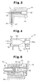
- the thermal spraying system uses a high-speed flame spraying machine 41 (hereinafter also referred to as "thermal spraying gun 41") shown in Fig. 3 instead of the thermal spraying gun 11 according to the first embodiment.
- a feeder 12 and thermal spraying powder used are the same as those in the first embodiment, and therefore explanations thereof will be omitted.
- the thermal spraying gun 41 jets thermal spraying powder by softening or melting it using a combustion gas of fuel and oxygen.
- the thermal spraying gun 41 is provided with a combustion chamber 42 where combustion of fuel and oxygen takes place.
- the combustion chamber 42 is directly open to the outside at the front end (right side in Fig. 3) of the thermal spraying gun 41.
- the combustion chamber 42 is also open to the outside at the rear end (bottom left in Fig. 3) of the thermal spraying gun 41 through the first holes 43 and 44.
- the first holes 43 and 44 serve as channels for introducing fuel and oxygen into the combustion chamber 42.
- the combustion chamber 42 is also open to the outside at the rear end (left side in Fig. 3) of the thermal spraying gun 41 through a second hole 45.
- the second hole 45 is connected to a carrier tube 16 (not shown in Fig. 3) which extends from a feeder 12 (see Fig. 2).
- Thermal spraying powder carried from the feeder 12 through the carrier tube 16 into the thermal spraying gun 41 is passed through the second hole 45 and supplied to the combustion chamber 42 and softened or melted by a combustion gas in the combustion chamber 42 and directly jetted out from the combustion chamber 42 to the outside.
- a channel 46 for a coolant (air) to cool the combustion chamber 42 is formed outside the combustion chamber 42.
- the coolant is introduced from a supply source (not shown) of the coolant into the channel 46.
- the thermal spraying powder is softened or melted by the combustion gas in the combustion chamber 42 and directly jetted out from the combustion chamber 42 to the outside. This prevents the softened or melted thermal spraying powder from adhering and depositing onto the inner wall of the jet nozzle and prevents spitting from occurring.
- the flying speed of the thermal spraying powder jetted out from the thermal spraying gun 41 is slower than the flying speed of the thermal spraying powder jetted out from a conventional high-speed flame spraying machine provided with a jet nozzle. For this reason, a thermal spray coating obtained is likely to contain many pores.
- the thermal spraying powder used in this embodiment is fine grains having a D 90% of no more than 20 ⁇ m, and therefore it is easily softened or melted. Therefore, even if the flying speed of the thermal spraying powder is slow, it is possible to obtain a dense thermal spray coating.
- the thermal spraying gun 41 generally uses propylene as a fuel, and therefore the temperature of the combustion gas is high and it is thereby possible to soften or melt thermal spraying powder more reliably than a conventional high-speed flame spraying machine.
- the thermal spraying system uses a high-speed flame spraying machine 51 (hereinafter also referred to as "thermal spraying gun 51") shown in Fig. 4 instead of the thermal spraying gun 11 according to the first embodiment.
- a feeder 12 and thermal spraying powder used are the same as those in the first embodiment, and therefore explanations thereof will be omitted.
- the thermal spraying gun 51 jets thermal spraying powder by softening or melting it using a combustion gas of fuel and oxygen.
- the thermal spraying gun 51 is provided with a combustion chamber 52 where combustion of fuel and oxygen takes place.
- the combustion chamber 52 is open to the outside at the rear end (left side in Fig. 4) of the thermal spraying gun 51 through first holes 53 and 54.
- the first holes 53 and 54 serve as channels for introducing fuel and oxygen into the combustion chamber 52.
- the combustion chamber 52 is also open to the outside at an exhaust port 55a at the front end (right side in Fig. 4) of the thermal spraying gun 51 through a second hole 55 (jet nozzle).
- the second hole 55 serves as a channel to discharge combustion gas produced when combustion of fuel and oxygen takes place in the combustion chamber 52 from the exhaust port 55a to the outside.
- the second hole 55 is connected to a carrier tube 16 which extends from the feeder 12 (see Fig. 2). Thermal spraying powder carried from the feeder 12 through the carrier tube 16 into the thermal spraying gun 51 is supplied to the combustion gas circulating through the second hole 55 toward the exhaust port 55a, softened or melted by the combustion gas in the second hole 55 and jetted out.
- the length L from the downstream end of the carrier tube 16, that is, the supply port of the thermal spraying powder, to the exhaust port 55a is no more than 8 cm, or preferably no more than 6.5 cm.
- a channel 56 for a coolant (water) to cool the combustion chamber 52 is formed outside the combustion chamber 52.
- the coolant is introduced from a supply source (not shown) of the coolant into the channel 56.
- the length L from the supply port of the thermal spraying powder to the exhaust port 55a of the thermal spraying gun 51 is short.
- the flying speed of the thermal spraying powder jetted out from the thermal spraying gun 51 is slower than the flying speed of the thermal spraying powder jetted out from a conventional high-speed flame spraying machine.
- a thermal spray coating obtained is likely to contain many pores.
- the thermal spraying material used in this embodiment is fine grains having a D 90% of no more than 20 ⁇ m, and therefore it is easily softened or melted. Therefore, even if the flying speed of the thermal spraying powder is slow, it is possible to obtain a dense thermal spray coating.
- by narrowing the inner diameter of the second hole 55, which is the channel for the combustion gas it is possible to increase the flying speed of thermal spraying powder of the thermal spraying gun 51.
- the thermal spraying system uses a plasma thermal spraying machine 61 (hereinafter also referred to as "thermal spraying gun 61") shown in Fig. 5 instead of the thermal spraying gun 11 according to the first embodiment.
- a feeder 12 and thermal spraying powder used are the same as those in the first embodiment, and therefore explanations thereof will be omitted.
- the thermal spraying gun 61 discharges thermal spraying powder by softening or melting it using a plasma jet.
- the thermal spraying gun 61 is provided with a cathode 62 and an anode 63.
- a plasma jet is formed through ignition of arc discharge between the two electrodes 62 and 63.
- the thermal spraying gun 61 is provided with an introduction path 64 for a plasma working gas (argon, helium, etc.).
- the plasma working gas is supplied to close to the electrodes 62 and 63 through the introduction path 64 from a supply source (not shown).
- a channel 65 for a coolant (water) to cool the electrodes 62 and 63 is formed around the electrodes 62 and 63.
- the coolant is introduced from a supply source (not shown) into the channel 65 through an introduction path 66 and exhausted through an exhaust path 67.
- An exhaust port 68 for discharging a plasma jet is formed at the front end (right side in Fig. 5) of the thermal spraying gun 61.
- the downstream end of a carrier tube 16 which extends from the feeder 12 is provided in front of the exhaust port 68.
- the thermal spraying powder carried from the feeder 12 through the carrier tube 16 to the thermal spraying gun 61 is supplied to the plasma jet discharged from the exhaust port 68 is softened or melted by the plasma jet outside the thermal spraying gun 61 and jetted out.
- the thermal spraying gun 61 does not soften or melt thermal spraying powder inside the thermal spraying machine as in the case of a conventional thermal spraying machine but softens or melts thermal spraying powder outside the thermal spraying gun 61. This eliminates the possibility that spitting may occur.
- the first to third embodiments use the high-speed flame spraying machine 11 as the thermal spraying machine, but the present invention may also be implemented using other gas-based thermal spraying machines. Furthermore, the present invention may also be implemented using an electric thermal spraying machine such as a plasma thermal spraying machine.
- the fourth embodiment uses the plasma thermal spraying machine 61 as the thermal spraying machine, but the present invention may also be implemented using a gas-based thermal spraying machine such as a high-speed flame spraying machine.
- the first embodiment uses circular holes for the nozzle 18, but it may also be arc-shaped long holes.
- the first embodiment forms the nozzle 18 in a ring shape, but the nozzle 18 may also be formed in a polygonal ring shape.
- the first embodiment uses two carrier tubes 16 connected to the thermal spraying gun 11, but the number of the carrier tubes 16 may also be one or three or more.
- the fourth embodiment uses one carrier tube 16 connected to the thermal spraying gun 61, but the number of the carrier tubes 16 may also be two or more.
- thermal spraying powder having a composition and particle size distribution as shown in Table 1 was thermal-sprayed onto a base material (SS400 steel sheet).
- base material SS400 steel sheet
- the surface roughness and denseness of the thermal spray coating were evaluated as shown below and the results are shown in Table 1.
- Thermal spraying machine high-speed flame spraying machine " ⁇ -Gun” (corresponds to the thermal spraying machine 11 according to the first embodiment) manufactured by Whitco Japan, oxygen flow rate: 1900 scfh (893 ml/min), kerosene flow rate: 5.1 gph (0.32 l/min), thermal spraying distance: 250 mm
- Thermal spraying machine plasma thermal spraying machine "SG-100" (corresponds to the thermal spraying machine 61 according to the fourth embodiment) manufactured by PRAXAIR, Inc., current: 700 A, Ar: 50 psi (345 kPa), He: 90 psi (620 kpa), thermal spraying powder supply unit: external supply type
- Thermal spraying machine high-speed flame spraying machine "Diamond jet standard type (DJ-STD)" (corresponds to the thermal spraying machine 41 according to the second embodiment) manufactured by SULZER METCO, oxygen flow rate: 40 scales, propylene flow rate: 38 scales, airflow rate: 47 scales, thermal spraying distance: 200 mm
- Thermal spraying machine high-speed flame spraying machine "JET-KOTE” manufactured by DELORO STEELITE COATING, oxygen flow rate: 1000 scales, propylene flow rate: 63 scales, pilot gas (H 2 ) flow rate: 10 scales, pilot gas (O 2 ) flow rate: 10 scales, thermal spraying distance: 200 mm
- the surface roughness Ra of a thermal spray coating having a thickness of 200 ⁇ m formed on a base material was measured. Evaluations were made with cases having a surface roughness Ra of less than 1.0 ⁇ m measured under the following conditions marked with o ⁇ , 1.0 ⁇ m or more and less than 2.0 ⁇ m marked with ⁇ , 2.0 ⁇ m or more and less than 3.0 ⁇ m marked with ⁇ and 3.0 ⁇ m or more marked with ⁇ .
- a thermal spray coating having a thickness of 30 ⁇ m formed on a base material was subjected to a salt-spray test compliant with JIS Z 2371. That is, salt water was sprayed over the surface of a base material covered with a thermal spray coating. 24 hours after salt water was sprayed, the appearance was visually checked and evaluations were made in which cases with rust were marked with ⁇ and cases with no rust marked were with ⁇ .
Landscapes
- Chemical & Material Sciences (AREA)
- Engineering & Computer Science (AREA)
- Physics & Mathematics (AREA)
- Plasma & Fusion (AREA)
- Chemical Kinetics & Catalysis (AREA)
- Materials Engineering (AREA)
- Mechanical Engineering (AREA)
- Metallurgy (AREA)
- Organic Chemistry (AREA)
- Coating By Spraying Or Casting (AREA)
- Application Of Or Painting With Fluid Materials (AREA)
- Nozzles (AREA)
Abstract
A thermal spraying method and thermal spraying system of the present invention jets thermal spraying powder supplied from a feeder through a connecting conduit by softening or melting the thermal spraying powder using a thermal spraying machine. By setting the internal atmosphere in the connecting conduit to a negative pressure relative to the atmosphere near the intake end of the connecting conduit, the thermal spraying powder stored in the feeder is suctioned into the intake end of the connecting conduit. The thermal spraying powder suctioned into the intake end of the connecting conduit is carried to the discharge end of the connecting conduit, introduced inside a cylindrical air flow jetted from the nozzle provided in the thermal spraying machine or introduced into a combustion chamber provided in the thermal spraying machine or into the jet nozzle, softened or melted and jetted out. <IMAGE>
Description
The present invention relates to a thermal spraying
method and thermal spraying system for forming a thermal spray
coating on a base material.
A thermal spray coating is formed by heating a thermal
spraying material and spraying the softened or melted thermal
spraying material over a base material, and therefore the
surface thereof is substantially not smooth but rough. For
this reason, in applications requiring smoothness such as a
paper manufacturing roll, etc., the surface of a thermal spray
coating is polished to obtain desired surface roughness.
However, the thermal spray coating generally has high hardness
and polishing is often difficult. Especially in the case of a
thermal spray coating obtained by thermal spraying cermet, it
is necessary to apply polishing using diamond grain, which
involves a considerable increase in cost. Therefore, there is
a demand for means for obtaining a thermal spray coating with
small surface roughness so as to omit or simplify polishing
after thermal spraying.
Furthermore, a thermal spray coating has substantially a
porous structure and may include through holes (holes which
extend from the surface of the thermal spray coating to the
base material). A thermal spray coating without any through
holes is sometimes required depending on the application such
as when thermal spraying is used as an alternative technology
for plating. In such a case, through holes are conventionally
prevented by providing a certain amount of thickness (several
hundred µm) for the thermal spray coating. However, the cost
basically increases as the thickness increases, and therefore
the thermal spray coating is preferably as thin as possible.
Thus, the thermal spray coating is required not to include air
through holes however thin it may be.
As one of a means for responding to such a demand, a fine
powder may be used as a thermal spraying material. If fine
thermal spraying powder can be thermal sprayed, it is possible
to obtain a thermal spray coating with small surface
roughness. Furthermore, since the inner structure of the
thermal spray coating becomes dense, even with a thin film, it
is expected to obtain a thermal spray coating without
containing any through holes. However, when fine powder is
thermal sprayed, the following additional problems are
produced. Thus, it is extremely difficult to obtain a dense
thermal spray coating with small surface roughness.
First, a phenomenon called "spitting" may occur with a
thermal spraying machine. Spitting refers to a phenomenon
that a softened or melted thermal spraying material is adhered
to or deposited on the inner wall of the jet nozzle of the
thermal spraying machine and the depositions fall off and mix
into the coating. Spitting may degenerate the quality of a
thermal spray coating. Furthermore, the thermal spraying
material deposited on the inner wall of the jet nozzle clogs
the jet nozzle and prevents formation of the thermal spray
coating itself. When the thermal spraying material is a fine
powder, the powder is excessively melted and likely to stick
to the inner wall of the jet nozzle and thereby produce
spitting in particular.
Furthermore, the fluidity of thermal spraying powder
decreases as the powder becomes finer, which causes problems
like rippling and bridging in the feeder. When the supply of
thermal spraying powder to the thermal spraying machine is not
stable due to rippling, the quality of the thermal spray
coating degenerates considerably. Furthermore, when thermal
spraying powder forms a bridge, it is impossible to supply
thermal spraying powder to the thermal spraying machine
smoothly and the supply may be stopped in the worst case.
It is an object of the present invention to provide a
thermal spraying method and thermal spraying system capable of
forming a dense thermal spray coating with small surface
roughness.
In order to attain the above described object, the
present invention provides a thermal spraying method for
jetting thermal spraying powder supplied from a feeder through
a connecting conduit by softening or melting the thermal
spraying powder using a thermal spraying machine. The thermal
spraying method includes the steps of suctioning thermal
spraying powder stored in the feeder into the intake end of
the connecting conduit by setting the internal atmosphere in
the connecting conduit to a negative pressure relative to the
atmosphere near the intake end of the connecting conduit,
carrying the thermal spraying powder suctioned into the intake
end of the connecting conduit to the discharge end of the
connecting conduit, introducing the thermal spraying powder
from the discharge end of the connecting conduit inside a
cylindrical air flow jetted from a nozzle provided in the
thermal spraying machine and jetting the thermal spraying
powder by softening or melting the thermal spraying powder
inside the air flow.
The present invention provides another thermal spraying
method. The thermal spraying method includes the steps of
suctioning thermal spraying powder stored in the feeder into
the intake end of the connecting conduit by setting the
internal atmosphere in the connecting conduit to a negative
pressure relative to the atmosphere near the intake end of the
connecting conduit, carrying the thermal spraying powder
suctioned into the intake end of the connecting conduit to the
discharge end of the connecting conduit and introducing the
thermal spraying powder from the discharge end of the
connecting conduit into a combustion chamber provided in a
thermal spraying machine and jetting the thermal spraying
powder directly from the combustion chamber to outside by
softening or melting the thermal spraying powder using a
combustion gas generated in the combustion chamber.
The present invention provides a further thermal spraying
method. The thermal spraying method comprises the steps of
suctioning the thermal spraying powder stored in the feeder
into the intake end of the connecting conduit by setting the
internal atmosphere in the connecting conduit to a negative
pressure relative to the atmosphere near the intake end of the
connecting conduit, carrying the thermal spraying powder
suctioned into the intake end of the connecting conduit to the
discharge end of the connecting conduit and introducing the
thermal spraying powder from the discharge end of the
connecting conduit into a place in a jet nozzle provided in
the thermal spraying machine within 8 cm from the downstream
end of the jet nozzle toward the upstream and jetting the
thermal spraying powder by softening or melting the thermal
spraying powder from the downstream end of the jet nozzle to
the outside.
The present invention provides a still further thermal
spraying method. The thermal spraying method comprises the
steps of suctioning the thermal spraying powder stored in the
feeder into the intake end of the connecting conduit by
setting the internal atmosphere in the connecting conduit to a
negative pressure relative to the atmosphere near the intake
end of the connecting conduit, carrying the thermal spraying
powder suctioned into the intake end of the connecting conduit
to the discharge end of the connecting conduit and supplying a
heat source discharged by the thermal spraying machine from
the exhaust port to the outside, with the thermal spraying
powder from the discharge end of the connecting conduit
downstream from the exhaust port in a circulation direction of
the heat source and jetting the thermal spraying powder by
softening or melting the thermal spraying powder using the
heat source.
The present invention also provides a thermal spraying
system for jetting thermal spraying powder supplied from a
feeder by softening or melting it in a thermal spraying
machine. The thermal spraying system comprises a reservoir
which stores the thermal spraying powder, a nozzle provided in
a thermal spraying machine, the nozzle jetting a cylindrical
air flow, a connecting conduit, the intake end of which is
provided near the surface of the thermal spraying powder
stored in the reservoir and the discharge end of which is
provided inside the cylindrical air flow, the connecting
conduit carrying thermal spraying powder from the intake end
to the discharge end and introducing the thermal spraying
powder from the discharge end to the inside of the cylindrical
air flow, a mechanism which sets the internal atmosphere of
the connecting conduit to a negative pressure relative to the
atmosphere near the intake end of the connecting conduit to
thereby suction the thermal spraying powder stored in the
reservoir into the intake end of the connecting conduit and a
mechanism which jets the thermal spraying powder discharged
from the discharge end of the connecting conduit by softening
or melting the thermal spraying powder inside the cylindrical
air flow.
The present invention provides another thermal spraying
system. The thermal spraying system comprises a reservoir
which stores the thermal spraying powder, a combustion chamber
provided in a thermal spraying machine, the combustion chamber
generating a combustion gas, a connecting conduit, the intake
end of which is provided near the surface of the thermal
spraying powder stored in the reservoir and the discharge end
of which is provided inside the combustion chamber, the
connecting conduit carrying thermal spraying powder from the
intake end to the discharge end and introducing the thermal
spraying powder from the discharge end into the combustion
chamber, a mechanism which sets the internal atmosphere of the
connecting conduit to a negative pressure relative to the
atmosphere near the intake end of the connecting conduit to
thereby suction the thermal spraying powder stored in the
reservoir into the intake end of the connecting conduit and a
mechanism which jets the thermal spraying powder discharged
from the discharge end of the connecting conduit directly from
the combustion chamber to the outside by softening or melting
the thermal spraying powder inside the combustion chamber.
The present invention provides a further thermal spraying
system. The thermal spraying system comprises a reservoir
which stores the thermal spraying powder, a jet nozzle
provided in a thermal spraying machine, the jet nozzle jetting
the softened or melted thermal spraying powder from the
downstream end to the outside, a connecting conduit, the
intake end of which is provided near the surface of the
thermal spraying powder stored in the reservoir and the
discharge end of which is provided inside the jet nozzle, the
connecting conduit carrying thermal spraying powder from the
intake end to the discharge end and introducing the thermal
spraying powder from the discharge end to a place in the jet
nozzle within 8 cm from the downstream end of the jet nozzle
toward the upstream, a mechanism which sets the internal
atmosphere of the connecting conduit to a negative pressure
relative to the atmosphere near the intake end of the
connecting conduit to thereby suction the thermal spraying
powder stored in the reservoir into the intake end of the
connecting conduit and a mechanism which jets the thermal
spraying powder discharged from the discharge end of the
connecting conduit from the downstream end of the jet nozzle
to the outside by softening or melting the thermal spraying
powder inside the jet nozzle.
The present invention provides a still further thermal
spraying system. The thermal spraying system comprises a
reservoir which stores the thermal spraying powder, an exhaust
port provided in a thermal spraying machine, the exhaust port
discharging a heat source to the outside, a connecting
conduit, the intake end of which is provided near the surface
of the thermal spraying powder stored in the reservoir and the
discharge end of which is provided outside the exhaust port,
the connecting conduit carrying thermal spraying powder from
the intake end to the discharge end and supplying the thermal
spraying powder from the discharge end to the heat source
discharged from the exhaust port, a mechanism which sets the
internal atmosphere of the connecting conduit to a negative
pressure relative to the atmosphere near the intake end of the
connecting conduit to thereby suction the thermal spraying
powder stored in the reservoir into the intake end of the
connecting conduit and a mechanism which jets the thermal
spraying powder discharged from the discharge end of the
connecting conduit by softening or melting the thermal
spraying powder using the heat source discharged from the
exhaust port.
A first embodiment of the present invention will be
explained with reference to Figs. 1(a) to 2.
A thermal spraying system according to this embodiment is
provided with a high-speed flame spraying machine 11
(hereinafter also referred to as "thermal spraying gun 11") as
a thermal spraying machine shown in Figs. 1(a) to 1(c) and a
feeder 12 shown in Fig. 2.
First, the thermal spraying gun 11 will be explained with
reference to Figs. 1(a) to 1(c). The thermal spraying gun 11
jets thermal spraying powder as a thermal spraying material by
softening or melting it using a combustion gas of fuel and
oxygen. The thermal spraying gun 11 is provided with a
combustion chamber 13 where combustion of fuel and oxygen
takes place. The combustion chamber 13 is open to the outside
at the rear end (left side in Fig. 1(a)) of the thermal
spraying gun 11 through a first hole 14. The first hole 14
serves as a channel to introduce fuel and oxygen into the
combustion chamber 13. The combustion chamber 13 is also open
to the outside at an exhaust port 15a at the front end (right
side in Fig. 1(a)) of the thermal spraying gun 11 through a
second hole 15. The second hole 15 serves as a channel to
discharge a combustion gas produced by combustion of fuel and
oxygen in the combustion chamber 13 from the exhaust port 15a
to the outside.
A forward-facing (facing downstream in the circulation
direction of the combustion gas in the second hole 15) stepped
surface 17 is formed at some midpoint in the second hole 15.
On the stepped surface 17, a nozzle 18 is formed, which jets a
cylindrical air flow 20 toward the downstream direction in the
circulation direction of the combustion gas. The compressed
gas making up the cylindrical air flow 20 is supplied from a
supply source of a compressed gas (not shown) to the thermal
spraying gun 11, passed through an introduction path 19 and is
jetted from the nozzle 18. The nozzle 18 is made up of a
plurality of circular holes and these circular holes are
arranged in a ring shape on the stepped surface 17 (see Fig.
1(b)). The combustion gas circulating through the second hole
15 toward the exhaust port 15a passes inside the cylindrical
air flow 20 jetted from the nozzle 18.
A carrier tube 16 which extends from the feeder 12 (see
FIG. 2) is connected at some midpoint in the second hole which
is a position downstream from the nozzle 18 in the circulation
direction of the combustion gas. The thermal spraying powder
carried from the feeder 12 to the thermal spraying gun 11
through the carrier tube 16 is supplied to the combustion gas
circulating inside the cylindrical air flow 20 toward the
exhaust port 15a and softened or melted by the combustion gas
inside the cylindrical air flow 20 and jetted out.
A channel 21 for a coolant to cool the combustion chamber
13 is formed outside the combustion chamber 13. The coolant
is introduced from a supply source (not shown) of the coolant
through an introduction path 22 to the channel 21 and
exhausted through an exhaust path 23.
Then, the feeder 12 will be explained with reference to
Fig. 2. The feeder 12 supplies thermal spraying powder to the
thermal spraying gun 11. The feeder 12 is provided with a
reservoir 24 which stores the thermal spraying powder. The
reservoir 24 is housed in a sealed container 25. The
reservoir 24 is provided with a feed nozzle 26. The bottom
end (upstream end) of the feed nozzle 26 is placed near the
surface of the thermal spraying powder stored in the reservoir
24 and the top end (downstream end) of the feed nozzle 26 is
connected to the carrier tube 16 (see Fig. 1(a)) and led out
of the sealed container 25. The state in which the bottom end
of the feed nozzle 26 is placed "near the surface of the
thermal spraying powder stored in the reservoir 24" means not
only a state in which there is a small gap between the bottom
end of the feed nozzle 26 and the surface of the thermal
spraying powder but also a state in which the bottom end of
the feed nozzle 26 contacts the surface of the thermal
spraying powder and a state in which the bottom end of the
feed nozzle 26 is slightly buried in the thermal spraying
powder.
An inlet 27 is formed in the sealed container 25 to
introduce a carrier gas (e.g., nitrogen gas) into the sealed
container 25. When the carrier gas is fed into the sealed
container 25 from the inlet 27, the atmosphere in the feed
nozzle 26 becomes a negative pressure relative to the
atmosphere near the bottom end of the feed nozzle 26, and the
thermal spraying powder is suctioned together with the carrier
gas into the feed nozzle 26. The thermal spraying powder
suctioned into the feed nozzle 26 is passed through the
carrier tube 16 together with the carrier gas and carried to
the thermal spraying gun 11.
The feed nozzle 26 is moved up and down by a stepping
motor 28 through a gear mechanism 29. The driving of the
stepping motor 28 is controlled by a feed nozzle controller 31
based on the surface position of the thermal spraying powder
in the reservoir 24 detected by a laser sensor 30. The feed
nozzle controller 31 is under feedback control of a feeder
controller 32 based on information on the supply speed of the
thermal spraying powder detected by a weight sensor 33. The
surface of the thermal spraying powder in the reservoir 24 is
smoothed by a smoother (not shown) by a motor 34 driving the
rotation of the reservoir 24.
It is an essential condition for the thermal spraying
powder used in the thermal spraying system of this embodiment
to have D90% of no more than 20 µm. D90% is the diameter of
grains making up powder when a value obtained by adding up the
volume of the grains in ascending order of grain diameter is
equal to 90% of the sum of the volume of all the grains. When
D90% exceeds 20 µm, it is not possible to obtain a dense
thermal spray coating with small surface roughness. The value
of D90% of the thermal spraying powder is measured using a
laser diffraction type particle size analyzer (e.g., "LA-300"
manufactured by HORIBA, Ltd.).
This embodiment has the following advantages.
The thermal spraying powder is softened or melted inside
the cylindrical air flow 20 jetted from the nozzle 18, passed
inside the cylindrical air flow 20, and jetted out. This
makes it possible to suppress the adhesion and deposition of
the softened or melted thermal spraying powder on the inner
wall of the second hole 15 and suppress the generation of
spitting.
The feeder 12 sets the atmosphere in the feed nozzle 26
to a negative pressure relative to the atmosphere near the
bottom end of the feed nozzle 26 and thereby suctions the
thermal spraying powder together with the carrier gas into the
feed nozzle 26. For this reason, intake of the thermal
spraying powder into the feed nozzle 26 is not dependent on
the fluidity of the thermal spraying powder. Therefore, even
if the thermal spraying powder is fine grains, it is possible
to prevent the thermal spraying powder from forming a bridge
or prevent the supply of thermal spraying powder from
rippling.
The thermal spraying system of this embodiment suppresses
spitting at the thermal spraying gun 11 and bridging and
rippling at the feeder 12. Thus, it is possible to supply and
thermal-spray fine thermal spraying powder stably and form a
dense thermal spray coating with small surface roughness.
The high-speed flame spraying method accelerates thermal
spraying powder much more than other thermal spraying methods
and causes thermal spraying powder to collide with the base
material strongly. For this reason, it is possible to form a
dense thermal spray coating with small surface roughness more
reliably.
Hereinafter, a second embodiment of the present invention
will be explained with reference to Fig. 3.
As the thermal spraying machine, the thermal spraying
system according to this embodiment uses a high-speed flame
spraying machine 41 (hereinafter also referred to as "thermal
spraying gun 41") shown in Fig. 3 instead of the thermal
spraying gun 11 according to the first embodiment. Thus, a
feeder 12 and thermal spraying powder used are the same as
those in the first embodiment, and therefore explanations
thereof will be omitted.
The thermal spraying gun 41 jets thermal spraying powder
by softening or melting it using a combustion gas of fuel and
oxygen. The thermal spraying gun 41 is provided with a
combustion chamber 42 where combustion of fuel and oxygen
takes place. The combustion chamber 42 is directly open to
the outside at the front end (right side in Fig. 3) of the
thermal spraying gun 41. The combustion chamber 42 is also
open to the outside at the rear end (bottom left in Fig. 3) of
the thermal spraying gun 41 through the first holes 43 and 44.
The first holes 43 and 44 serve as channels for introducing
fuel and oxygen into the combustion chamber 42. The
combustion chamber 42 is also open to the outside at the rear
end (left side in Fig. 3) of the thermal spraying gun 41
through a second hole 45. The second hole 45 is connected to
a carrier tube 16 (not shown in Fig. 3) which extends from a
feeder 12 (see Fig. 2). Thermal spraying powder carried from
the feeder 12 through the carrier tube 16 into the thermal
spraying gun 41 is passed through the second hole 45 and
supplied to the combustion chamber 42 and softened or melted
by a combustion gas in the combustion chamber 42 and directly
jetted out from the combustion chamber 42 to the outside.
A channel 46 for a coolant (air) to cool the combustion
chamber 42 is formed outside the combustion chamber 42. The
coolant is introduced from a supply source (not shown) of the
coolant into the channel 46.
In this embodiment, the thermal spraying powder is
softened or melted by the combustion gas in the combustion
chamber 42 and directly jetted out from the combustion chamber
42 to the outside. This prevents the softened or melted
thermal spraying powder from adhering and depositing onto the
inner wall of the jet nozzle and prevents spitting from
occurring.
The flying speed of the thermal spraying powder jetted
out from the thermal spraying gun 41 is slower than the flying
speed of the thermal spraying powder jetted out from a
conventional high-speed flame spraying machine provided with a
jet nozzle. For this reason, a thermal spray coating obtained
is likely to contain many pores. However, the thermal
spraying powder used in this embodiment is fine grains having
a D90% of no more than 20 µm, and therefore it is easily
softened or melted. Therefore, even if the flying speed of
the thermal spraying powder is slow, it is possible to obtain
a dense thermal spray coating. Furthermore, the thermal
spraying gun 41 generally uses propylene as a fuel, and
therefore the temperature of the combustion gas is high and it
is thereby possible to soften or melt thermal spraying powder
more reliably than a conventional high-speed flame spraying
machine.
Hereafter, a third embodiment of the present invention
will be explained with reference to Fig. 4.
As the thermal spraying machine, the thermal spraying
system according to this embodiment uses a high-speed flame
spraying machine 51 (hereinafter also referred to as "thermal
spraying gun 51") shown in Fig. 4 instead of the thermal
spraying gun 11 according to the first embodiment. Thus, a
feeder 12 and thermal spraying powder used are the same as
those in the first embodiment, and therefore explanations
thereof will be omitted.
The thermal spraying gun 51 jets thermal spraying powder
by softening or melting it using a combustion gas of fuel and
oxygen. The thermal spraying gun 51 is provided with a
combustion chamber 52 where combustion of fuel and oxygen
takes place. The combustion chamber 52 is open to the outside
at the rear end (left side in Fig. 4) of the thermal spraying
gun 51 through first holes 53 and 54. The first holes 53 and
54 serve as channels for introducing fuel and oxygen into the
combustion chamber 52. The combustion chamber 52 is also open
to the outside at an exhaust port 55a at the front end (right
side in Fig. 4) of the thermal spraying gun 51 through a
second hole 55 (jet nozzle). The second hole 55 serves as a
channel to discharge combustion gas produced when combustion
of fuel and oxygen takes place in the combustion chamber 52
from the exhaust port 55a to the outside. The second hole 55
is connected to a carrier tube 16 which extends from the
feeder 12 (see Fig. 2). Thermal spraying powder carried from
the feeder 12 through the carrier tube 16 into the thermal
spraying gun 51 is supplied to the combustion gas circulating
through the second hole 55 toward the exhaust port 55a,
softened or melted by the combustion gas in the second hole 55
and jetted out.
The length L from the downstream end of the carrier tube
16, that is, the supply port of the thermal spraying powder,
to the exhaust port 55a is no more than 8 cm, or preferably no
more than 6.5 cm. By setting this length L to 8 cm or less,
it is possible to prevent spitting from occurring and setting
it to 6.5 cm or less further increases the effect.
A channel 56 for a coolant (water) to cool the combustion
chamber 52 is formed outside the combustion chamber 52. The
coolant is introduced from a supply source (not shown) of the
coolant into the channel 56.
Compared to a conventional high-speed flame spraying
machine, the length L from the supply port of the thermal
spraying powder to the exhaust port 55a of the thermal
spraying gun 51 is short. Thus, the flying speed of the
thermal spraying powder jetted out from the thermal spraying
gun 51 is slower than the flying speed of the thermal spraying
powder jetted out from a conventional high-speed flame
spraying machine. For this reason, a thermal spray coating
obtained is likely to contain many pores. However, the
thermal spraying material used in this embodiment is fine
grains having a D90% of no more than 20 µm, and therefore it is
easily softened or melted. Therefore, even if the flying
speed of the thermal spraying powder is slow, it is possible
to obtain a dense thermal spray coating. Furthermore, by
narrowing the inner diameter of the second hole 55, which is
the channel for the combustion gas, it is possible to increase
the flying speed of thermal spraying powder of the thermal
spraying gun 51.
Hereafter, a fourth embodiment of the present invention
will be explained with reference to Fig. 5.
As the thermal spraying machine, the thermal spraying
system according to this embodiment uses a plasma thermal
spraying machine 61 (hereinafter also referred to as "thermal
spraying gun 61") shown in Fig. 5 instead of the thermal
spraying gun 11 according to the first embodiment. Thus, a
feeder 12 and thermal spraying powder used are the same as
those in the first embodiment, and therefore explanations
thereof will be omitted.
The thermal spraying gun 61 discharges thermal spraying
powder by softening or melting it using a plasma jet. The
thermal spraying gun 61 is provided with a cathode 62 and an
anode 63. A plasma jet is formed through ignition of arc
discharge between the two electrodes 62 and 63. The thermal
spraying gun 61 is provided with an introduction path 64 for a
plasma working gas (argon, helium, etc.). The plasma working
gas is supplied to close to the electrodes 62 and 63 through
the introduction path 64 from a supply source (not shown). A
channel 65 for a coolant (water) to cool the electrodes 62 and
63 is formed around the electrodes 62 and 63. The coolant is
introduced from a supply source (not shown) into the channel
65 through an introduction path 66 and exhausted through an
exhaust path 67.
An exhaust port 68 for discharging a plasma jet is formed
at the front end (right side in Fig. 5) of the thermal
spraying gun 61. In front of the exhaust port 68, the
downstream end of a carrier tube 16 which extends from the
feeder 12 (see Fig. 2) is provided. The thermal spraying
powder carried from the feeder 12 through the carrier tube 16
to the thermal spraying gun 61 is supplied to the plasma jet
discharged from the exhaust port 68 is softened or melted by
the plasma jet outside the thermal spraying gun 61 and jetted
out.
The thermal spraying gun 61 does not soften or melt
thermal spraying powder inside the thermal spraying machine as
in the case of a conventional thermal spraying machine but
softens or melts thermal spraying powder outside the thermal
spraying gun 61. This eliminates the possibility that
spitting may occur.
The above described embodiments may also be modified as
follows.
The first to third embodiments use the high-speed flame
spraying machine 11 as the thermal spraying machine, but the
present invention may also be implemented using other gas-based
thermal spraying machines. Furthermore, the present
invention may also be implemented using an electric thermal
spraying machine such as a plasma thermal spraying machine.
The fourth embodiment uses the plasma thermal spraying
machine 61 as the thermal spraying machine, but the present
invention may also be implemented using a gas-based thermal
spraying machine such as a high-speed flame spraying machine.
The first embodiment uses circular holes for the nozzle
18, but it may also be arc-shaped long holes.
The first embodiment forms the nozzle 18 in a ring shape,
but the nozzle 18 may also be formed in a polygonal ring
shape.
The first embodiment uses two carrier tubes 16 connected
to the thermal spraying gun 11, but the number of the carrier
tubes 16 may also be one or three or more. The fourth
embodiment uses one carrier tube 16 connected to the thermal
spraying gun 61, but the number of the carrier tubes 16 may
also be two or more.
The present invention will be explained more specifically
using Examples and Comparative Examples as follows.
Using a thermal spraying system combining a thermal
spraying machine and a feeder as shown in Table 1, thermal
spraying powder having a composition and particle size
distribution as shown in Table 1 was thermal-sprayed onto a
base material (SS400 steel sheet). For the thermal spraying
powder whose thermal spray coating was successfully formed on
the base material, the surface roughness and denseness of the
thermal spray coating were evaluated as shown below and the
results are shown in Table 1.
Evaluations in the column of the coating formation in
Table 1 were made in which cases of successful formation of a
thermal spray coating were marked with ○, cases of a failure
to form a thermal spray coating due to spitting in the thermal
spraying machine were marked with ×, and cases of a failure
to supply thermal spraying powder from the feeder to the
thermal spraying machine resulting in a failure to form a
thermal spray coating were marked with ××. "AM-30" and "PL-25"
in the field of the feeder in Table 1 denote trade names
of the feeders manufactured by Technoserve Co., Ltd., and
"1264" is a trade name of the feeder manufactured by PRAXAIR,
Inc.
The thermal spraying conditions in the respective
Examples and Comparative Examples are as follows:
Thermal spraying machine: high-speed flame spraying
machine "-Gun" (corresponds to the thermal spraying machine
11 according to the first embodiment) manufactured by Whitco
Japan, oxygen flow rate: 1900 scfh (893 ml/min), kerosene flow
rate: 5.1 gph (0.32 l/min), thermal spraying distance: 250 mm
Thermal spraying machine: plasma thermal spraying machine
"SG-100" (corresponds to the thermal spraying machine 61
according to the fourth embodiment) manufactured by PRAXAIR,
Inc., current: 700 A, Ar: 50 psi (345 kPa), He: 90 psi (620
kpa), thermal spraying powder supply unit: external supply
type
Thermal spraying machine: high-speed flame spraying
machine "Diamond jet standard type (DJ-STD)" (corresponds to
the thermal spraying machine 41 according to the second
embodiment) manufactured by SULZER METCO, oxygen flow rate: 40
scales, propylene flow rate: 38 scales, airflow rate: 47
scales, thermal spraying distance: 200 mm
Thermal spraying machine: high-speed flame spraying
machine "JP-5000" manufactured by PRAXAIR/TAFA, length of
barrel (jet nozzle): 10.16 cm (= 4 inches), oxygen flow rate:
1900 scfh (893 ml/min), kerosene flow rate: 5.1 gph (0.32
l/min), thermal spraying distance: 380 mm
Thermal spraying machine: high-speed flame spraying
machine "JET-KOTE" manufactured by DELORO STEELITE COATING,
oxygen flow rate: 1000 scales, propylene flow rate: 63 scales,
pilot gas (H2) flow rate: 10 scales, pilot gas (O2) flow rate:
10 scales, thermal spraying distance: 200 mm
The surface roughness Ra of a thermal spray coating
having a thickness of 200 µm formed on a base material was
measured. Evaluations were made with cases having a surface
roughness Ra of less than 1.0 µm measured under the following
conditions marked with o ○, 1.0 µm or more and less than 2.0 µm
marked with ○, 2.0 µm or more and less than 3.0 µm marked
with Δ and 3.0 µm or more marked with ×.
Measuring machine: surface roughness measuring machine
"Surfcom 1400D-12" manufactured by Tokyo Seimitsu Co., Ltd.,
measuring length: 10.0 mm, cutoff wavelength: 0.8 mm,
measuring speed: 0.30 mm/sec, edge: r = 5 µm
A thermal spray coating having a thickness of 30 µm
formed on a base material was subjected to a salt-spray test
compliant with JIS Z 2371. That is, salt water was sprayed
over the surface of a base material covered with a thermal
spray coating. 24 hours after salt water was sprayed, the
appearance was visually checked and evaluations were made in
which cases with rust were marked with × and cases with no
rust marked were with ○.
| Thermal spraying machine | Feeder | Thermal spraying powder | Evaluation | ||||||
| Composition | Particle size distribution (µm) | Coating formation | Surface roughness Ra (µm) | Denseness | |||||
| D10% | D50% | D90% | |||||||
| Ex.1 | -gun | AM-30 | WC/12Co | 0.6 | 1.8 | 5.2 | ○ | o ○ (0.73) | ○ |
| Ex.2 | -gun | AM-30 | WC/12Co | 0.9 | 3.3 | 6.3 | ○ | o ○ (0.99) | ○ |
| Ex.3 | -gun | AM-30 | WC/12Co | 2.1 | 6.4 | 11.7 | ○ | ○ (1.52) | ○ |
| Ex.4 | -gun | AM-30 | Ni-20Cr | 2.7 | 6.0 | 10.1 | ○ | ○ (1.48) | ○ |
| Ex.5 | SG-100 | AM-30 | WC/12Co | 0.6 | 1.8 | 5.2 | ○ | o ○ (0.83) | ○ |
| Ex.6 | DJ-STD | AM-30 | WC/12Co | 0.6 | 1.8 | 5.2 | ○ | o ○ (0.82) | ○ |
| C.Ex.1 | -gun | AM-30 | WC/12Co | 9.7 | 23.5 | 37.1 | ○ | Δ (2.78) | ○ |
| C.Ex.2 | JP-5000 | AM-30 | WC/12Co | 0.6 | 1.8 | 5.2 | × | - | - |
| C.Ex.3 | JP-5000 | AM-30 | WC/12Co | 0.9 | 3.3 | 6.3 | × | - | - |
| C.Ex.4 | JP-5000 | AM-30 | WC/12Co | 2.1 | 6.4 | 11.7 | × | - | - |
| C.Ex.5 | Jet-Kote | AM-30 | WC/12Co | 0.6 | 1.8 | 5.2 | × | - | - |
| C.Ex.6 | -gun | PL-25 | WC/12Co | 0.6 | 1.8 | 5.2 | ×× | - | - |
| C.Ex.7 | -gun | PL-25 | WC/12Co | 0.9 | 3.3 | 6.3 | ×× | - | - |
| C.Ex.8 | -gun | PL-25 | WC/12Co | 2.1 | 6.4 | 11.7 | ×× | - | - |
| C.Ex.9 | -gun | 1264 | WC/12Co | 0.6 | 1.8 | 5.2 | ×× | - | - |
| C.Ex.10 | SG-100 | PL-25 | WC/12Co | 0.6 | 1.8 | 5.2 | ×× | - | - |
| C.Ex.11 | SG-100 | 1264 | WC/12Co | 0.6 | 1.8 | 5.2 | ×× | - | - |
| C.Ex.12 | JP-5000 | PL-25 | WC/12Co | 9.7 | 23.5 | 37.1 | × | - | - |
| C.Ex.13 | JP-5000 | PL-25 | WC/12Co | 18.6 | 27.7 | 42.8 | ○ | × (3.85) | × |
| C.Ex.14 | JP-5000 | PL-25 | Ni-20Cr | 8.6 | 22.9 | 35.2 | × | - | - |
| C.Ex.15 | JP-5000 | PL-25 | Ni-20Cr | 20.1 | 30.2 | 45.6 | ○ | × (3.92) | × |
As shown in Table 1, all the thermal spray coatings
obtained in Examples 1 to 6 were evaluated with regard to
surface roughness as excellent or good (o ○ or ○) and evaluated
with regard to denseness as good (○). On the contrary, the
cases of Comparative Examples 1 to 15 could not even form a
thermal spray coating except for Comparative Example 1,
Comparative Example 13 and Comparative Example 15, or although
they could form some thermal spray coating, their surface
roughness and denseness were evaluated as unacceptable (×).
Claims (10)
- A thermal spraying method for jetting thermal spraying powder supplied from a feeder through a connecting conduit by softening or melting the thermal spraying powder using a thermal spraying machine, the method comprising:suctioning thermal spraying powder stored in said feeder into the intake end of said connecting conduit by setting the internal atmosphere in said connecting conduit to a negative pressure relative to the atmosphere near the intake end of said connecting conduit;carrying the thermal spraying powder suctioned into the intake end of said connecting conduit to the discharge end of said connecting conduit; andintroducing the thermal spraying powder from the discharge end of said connecting conduit into a cylindrical air flow jetted from a nozzle provided in said thermal spraying machine and jetting said thermal spraying powder by softening or melting said thermal spraying powder inside the air flow.
- A thermal spraying method for jetting thermal spraying powder supplied from a feeder through a connecting conduit by softening or melting the thermal spraying powder using a thermal spraying machine, the method comprising:suctioning thermal spraying powder stored in said feeder into the intake end of said connecting conduit by setting the internal atmosphere in said connecting conduit to a negative pressure relative to the atmosphere near the intake end of said connecting conduit;carrying the thermal spraying powder suctioned into the intake end of said connecting conduit to the discharge end of said connecting conduit; andintroducing the thermal spraying powder from the discharge end of said connecting conduit into a combustion chamber provided in said thermal spraying machine and jetting said thermal spraying powder directly from said combustion chamber to the outside by softening or melting said thermal spraying powder using a combustion gas generated in said combustion chamber.
- A thermal spraying method for jetting thermal spraying powder supplied from a feeder through a connecting conduit by softening or melting the thermal spraying powder using a thermal spraying machine, the method comprising:suctioning thermal spraying powder stored in said feeder into the intake end of said connecting conduit by setting the internal atmosphere in said connecting conduit to a negative pressure relative to the atmosphere near the intake end of said connecting conduit;carrying the thermal spraying powder suctioned into the intake end of said connecting conduit to the discharge end of said connecting conduit; andintroducing the thermal spraying powder from the discharge end of said connecting conduit into a place in a jet nozzle provided in said thermal spraying machine, with said place being within 8 cm from the downstream end of said jet nozzle toward the upstream and jetting said thermal spraying powder by softening or melting said thermal spraying powder from the downstream end of said jet nozzle to the outside.
- A thermal spraying method for jetting thermal spraying powder supplied from a feeder through a connecting conduit by softening or melting the thermal spraying powder using a thermal spraying machine, the method comprising:suctioning thermal spraying powder stored in said feeder into the intake end of said connecting conduit by setting the internal atmosphere in said connecting conduit to a negative pressure relative to the atmosphere near the intake end of said connecting conduit;carrying the thermal spraying powder suctioned into the intake end of said connecting conduit to the discharge end of said connecting conduit; andsupplying a heat source discharged by said thermal spraying machine from the exhaust port to the outside, with the thermal spraying powder from the discharge end of said connecting conduit downstream from said exhaust port in a circulation direction of said heat source and jetting said thermal spraying powder by softening or melting said thermal spraying powder using said heat source.
- The method according to any one of claims 1 to 4, wherein the diameter of grains making up said thermal spraying powder when a value obtained by adding up the volume of the grains in ascending order of grain diameter is equal to 90% of the sum of the volume of all the grains, is no more than 20 µm.
- A thermal spraying system for jetting thermal spraying powder supplied from a feeder by softening or melting the thermal spraying powder using a thermal spraying machine, the system comprising:a reservoir which stores the thermal spraying powder;a nozzle provided in said thermal spraying machine, said nozzle jetting a cylindrical air flow;a connecting conduit, the intake end of which is provided near the surface of the thermal spraying powder stored in said reservoir and the discharge end of which is provided inside said cylindrical air flow, said connecting conduit carrying thermal spraying powder from the intake end to the discharge end and introducing the thermal spraying powder from the discharge end to the inside of said cylindrical air flow;a mechanism which sets the internal atmosphere of said connecting conduit to a negative pressure relative to the atmosphere near the intake end of said connecting conduit to thereby suction the thermal spraying powder stored in said reservoir into the intake end of said connecting conduit; anda mechanism which jets the thermal spraying powder discharged from the discharge end of said connecting conduit by softening or melting said thermal spraying powder inside said cylindrical air flow.
- A thermal spraying system for jetting thermal spraying powder supplied from a feeder by softening or melting the thermal spraying powder using a thermal spraying machine, the system comprising:a reservoir which stores the thermal spraying powder;a combustion chamber provided in said thermal spraying machine, said combustion chamber generating a combustion gas;a connecting conduit, the intake end of which is provided near the surface of the thermal spraying powder stored in said reservoir and the discharge end of which is provided inside said combustion chamber, said connecting conduit carrying thermal spraying powder from the intake end to the discharge end and introducing the thermal spraying powder from the discharge end into said combustion chamber;a mechanism which sets the internal atmosphere of said connecting conduit to a negative pressure relative to the atmosphere near the intake end of said connecting conduit to thereby suction the thermal spraying powder stored in said reservoir into the intake end of said connecting conduit; anda mechanism which jets the thermal spraying powder discharged from the discharge end of said connecting conduit directly from said combustion chamber to the outside by softening or melting said thermal spraying powder inside said combustion chamber.
- A thermal spraying system for jetting thermal spraying powder supplied from a feeder by softening or melting the thermal spraying powder using a thermal spraying machine, the system comprising:a reservoir which stores the thermal spraying powder;a jet nozzle provided in said thermal spraying machine, said jet nozzle jetting the softened or melted thermal spraying powder from the downstream end to the outside;a connecting conduit, the intake end of which is provided near the surface of the thermal spraying powder stored in said reservoir and the discharge end of which is provided inside said jet nozzle, said connecting conduit carrying thermal spraying powder from the intake end to the discharge end and introducing the thermal spraying powder from the discharge end to a place in said jet nozzle, with said place being within 8 cm from the downstream end of said jet nozzle toward the upstream;a mechanism which sets the internal atmosphere of said connecting conduit to a negative pressure relative to the atmosphere near the intake end of said connecting conduit to thereby suction the thermal spraying powder stored in said reservoir into the intake end of said connecting conduit; anda mechanism which jets the thermal spraying powder discharged from the discharge end of said connecting conduit from the downstream end of said jet nozzle to the outside by softening or melting said thermal spraying powder inside said jet nozzle.
- A thermal spraying system for jetting thermal spraying powder supplied from a feeder by softening or melting the thermal spraying powder using a thermal spraying machine, the system comprising:a reservoir which stores the thermal spraying powder;an exhaust port provided in said thermal spraying machine, said exhaust port discharging a heat source to the outside;a connecting conduit, the intake end of which is provided near the surface of the thermal spraying powder stored in said reservoir and the discharge end of which is provided outside said exhaust port, said connecting conduit carrying thermal spraying powder from the intake end to the discharge end and supplying the thermal spraying powder from the discharge end to the heat source discharged from said exhaust port;a mechanism which sets the internal atmosphere of said connecting conduit to a negative pressure relative to the atmosphere near the intake end of said connecting conduit to thereby suction the thermal spraying powder stored in said reservoir into the intake end of said connecting conduit; anda mechanism which jets the thermal spraying powder discharged from the discharge end of said connecting conduit by softening or melting said thermal spraying powder using the heat source discharged from said exhaust port.
- The system according to any one of claims 6 to 9, wherein the diameter of grains making up said thermal spraying powder when a value obtained by adding up the volume of the grains in ascending order of grain diameter is equal to 90% of the sum of the volume of all the grains, is no more than 20 µm.
Applications Claiming Priority (3)
| Application Number | Priority Date | Filing Date | Title |
|---|---|---|---|
| JP2001317497A JP2003129212A (en) | 2001-10-15 | 2001-10-15 | Thermal spray method |
| JP2001317497 | 2001-10-15 | ||
| PCT/JP2002/010685 WO2003033756A1 (en) | 2001-10-15 | 2002-10-15 | Method and system for thermal spraying |
Publications (2)
| Publication Number | Publication Date |
|---|---|
| EP1445343A1 true EP1445343A1 (en) | 2004-08-11 |
| EP1445343A4 EP1445343A4 (en) | 2004-11-24 |
Family
ID=19135358
Family Applications (1)
| Application Number | Title | Priority Date | Filing Date |
|---|---|---|---|
| EP02801574A Withdrawn EP1445343A4 (en) | 2001-10-15 | 2002-10-15 | Method and system for thermal spraying |
Country Status (4)
| Country | Link |
|---|---|
| US (1) | US20050000424A1 (en) |
| EP (1) | EP1445343A4 (en) |
| JP (1) | JP2003129212A (en) |
| WO (1) | WO2003033756A1 (en) |
Cited By (1)
| Publication number | Priority date | Publication date | Assignee | Title |
|---|---|---|---|---|
| EP1510593A1 (en) * | 2003-08-28 | 2005-03-02 | Siemens Aktiengesellschaft | Process for coating a component, component and powder |
Families Citing this family (9)
| Publication number | Priority date | Publication date | Assignee | Title |
|---|---|---|---|---|
| JP4885445B2 (en) | 2004-12-21 | 2012-02-29 | 株式会社フジミインコーポレーテッド | Thermal spray powder |
| US20060237556A1 (en) * | 2005-04-26 | 2006-10-26 | Spraying Systems Co. | System and method for monitoring performance of a spraying device |
| US20070210182A1 (en) * | 2005-04-26 | 2007-09-13 | Spraying Systems Co. | System and Method for Monitoring Performance of a Spraying Device |
| US20100094079A1 (en) | 2005-06-21 | 2010-04-15 | Ams Research Corporation | Method and Apparatus for Securing a Urethral Sling to Pubic Bone |
| JP5039346B2 (en) * | 2006-09-12 | 2012-10-03 | 株式会社フジミインコーポレーテッド | Thermal spray powder and thermal spray coating |
| EP1988185A1 (en) * | 2007-04-25 | 2008-11-05 | Sulzer Metco AG | Computer-aided process for setting particle-specific parameters in a thermal spray process |
| JP5185641B2 (en) * | 2008-01-30 | 2013-04-17 | 日鉄住金ハード株式会社 | High-speed gas spraying device, plasma spraying device, and injection port member |
| KR100924821B1 (en) | 2009-06-16 | 2009-11-03 | 주식회사 봉화라이너 | Spray coating apparatus |
| CN116103600B (en) * | 2022-12-01 | 2025-05-20 | 中国科学院金属研究所 | A multifunctional device for realizing multi-stage particle deposition and collection in thermal spraying |
Family Cites Families (24)
| Publication number | Priority date | Publication date | Assignee | Title |
|---|---|---|---|---|
| CH127548A (en) * | 1927-06-14 | 1928-09-01 | Schoop Max Dr Ulrich | Method and device for the production of homogeneous and smooth metal coatings, in particular for graphic purposes. |
| US2786779A (en) * | 1953-02-09 | 1957-03-26 | Dewrance & Co | Method and apparatus for powdered metal deposition by oxy-fuel gas flame |
| GB757711A (en) * | 1953-05-27 | 1956-09-26 | Dewrance & Co | Improvements in or relating to torches for forming flames from combustible gases such as oxygen and acetylene and supplying metal powder to the flames |
| US2800419A (en) * | 1953-11-27 | 1957-07-23 | Coast Metals Inc | Method and apparatus for hard surfacing metals |
| US2876732A (en) * | 1954-01-13 | 1959-03-10 | Dewrance & Co | Apparatus for depositing an annular metal coating upon a work-piece |
| LU34348A1 (en) * | 1955-05-02 | |||
| DE1571153A1 (en) * | 1962-08-25 | 1970-08-13 | Siemens Ag | Plasma spray gun |
| GB1520301A (en) * | 1975-06-25 | 1978-08-09 | Zachry Co H B | Coating system using tape encapsulated particulate coating material |
| NL7600738A (en) * | 1976-01-23 | 1977-07-26 | Plasmainvent Ag | DEVICE FOR PLASMA SYRINGES. |
| JPS55111859A (en) * | 1979-02-21 | 1980-08-28 | Nippon Sanso Kk | Supplying method of pulverized material to be flame-sprayed |
| FR2449479A1 (en) * | 1979-02-21 | 1980-09-19 | Nippon Oxygen Co Ltd | BURNER FOR POWDER SPRAY COATING |
| JPS5811261B2 (en) * | 1980-04-11 | 1983-03-02 | 新日本製鐵株式会社 | Method for forming thermal spray coating containing solid lubricant |
| US4546902A (en) * | 1981-11-02 | 1985-10-15 | Anderson James Y | Apparatus for controlling the rate of fluent material |
| EP0163776A3 (en) * | 1984-01-18 | 1986-12-30 | James A. Browning | Highly concentrated supersonic flame spray method and apparatus with improved material feed |
| JPS61210170A (en) * | 1985-03-14 | 1986-09-18 | Hitachi Zosen Corp | Thermal spraying method of ceramic powder |
| US4696855A (en) * | 1986-04-28 | 1987-09-29 | United Technologies Corporation | Multiple port plasma spray apparatus and method for providing sprayed abradable coatings |
| US4869936A (en) * | 1987-12-28 | 1989-09-26 | Amoco Corporation | Apparatus and process for producing high density thermal spray coatings |
| EP0357694B1 (en) * | 1988-02-01 | 1991-10-30 | Nova-Werke Ag | Device for producing an inert gas envelope for plasma spraying |
| JP2770968B2 (en) * | 1988-12-12 | 1998-07-02 | バブコツク日立株式会社 | Chromium carbide-metal composite powder for high energy spraying |
| DE3927168A1 (en) * | 1989-08-17 | 1991-02-21 | Hoechst Ag | METHOD FOR THERMALLY SPRAYING OXIDE-CERAMIC SUPRAL-CONDUCTING MATERIALS |
| US5013883A (en) * | 1990-05-18 | 1991-05-07 | The Perkin-Elmer Corporation | Plasma spray device with external powder feed |
| DE4210900A1 (en) * | 1992-04-02 | 1993-10-14 | Hoechst Ag | Process for producing an adhesive bond between copper layers and ceramic |
| DE19838275A1 (en) * | 1998-08-22 | 2000-02-24 | Itw Gema Ag | Manual spray coating pistol has manually displaceable control element on pistol exterior for setting parameter(s) of operating media, including coating material, electrode electrical energy |
| JP2001181817A (en) * | 1999-12-22 | 2001-07-03 | Ishikawajima Harima Heavy Ind Co Ltd | Thermal spraying method and thermal spraying device |
-
2001
- 2001-10-15 JP JP2001317497A patent/JP2003129212A/en active Pending
-
2002
- 2002-10-15 EP EP02801574A patent/EP1445343A4/en not_active Withdrawn
- 2002-10-15 US US10/492,824 patent/US20050000424A1/en not_active Abandoned
- 2002-10-15 WO PCT/JP2002/010685 patent/WO2003033756A1/en not_active Ceased
Cited By (1)
| Publication number | Priority date | Publication date | Assignee | Title |
|---|---|---|---|---|
| EP1510593A1 (en) * | 2003-08-28 | 2005-03-02 | Siemens Aktiengesellschaft | Process for coating a component, component and powder |
Also Published As
| Publication number | Publication date |
|---|---|
| US20050000424A1 (en) | 2005-01-06 |
| JP2003129212A (en) | 2003-05-08 |
| EP1445343A4 (en) | 2004-11-24 |
| WO2003033756A1 (en) | 2003-04-24 |
Similar Documents
| Publication | Publication Date | Title |
|---|---|---|
| EP1407824B1 (en) | High-velocity flame spray gun and spray method using the same | |
| EP1445343A1 (en) | Method and system for thermal spraying | |
| US6610959B2 (en) | Single-wire arc spray apparatus and methods of using same | |
| EP1880034B1 (en) | Method and apparatus for fine particle liquid suspension feed for thermal spray system and coatings formed therefrom | |
| US5043548A (en) | Axial flow laser plasma spraying | |
| US4964568A (en) | Shrouded thermal spray gun and method | |
| US6322856B1 (en) | Power injection for plasma thermal spraying | |
| EP0377452B1 (en) | Thermal spray method for producing glass mold plungers | |
| EP0374703B1 (en) | Wire and powder thermal spray gun | |
| KR20060050588A (en) | Replaceable Throat Insert of Dynamic Injection Nozzle | |
| JP3612568B2 (en) | Metal film forming method and spraying apparatus by HVOF spray gun | |
| CA2259190A1 (en) | Thermal spraying method and apparatus | |
| JPH10226869A (en) | Plasma spraying method | |
| EP0530637A1 (en) | Plasma spraying method and apparatus and sprayed film obtained by the method | |
| JP2002542391A (en) | Liquid crystal polymer coating method | |
| KR101986306B1 (en) | Vacuum suspension plasma spray aparattus and vacuum suspension plasma spray method | |
| CN1496763A (en) | High-speed flame spraying gun and spraying method using the spraying gun | |
| JP2877058B2 (en) | Film formation method | |
| KR100599552B1 (en) | Coating method to improve wear resistance of spindle disk surface | |
| KR100770938B1 (en) | Production device for multiple-system film and coating tool for multiple-system film | |
| EP0825273B1 (en) | Coating substrates with high temperature ceramics | |
| JP2967604B2 (en) | Deposition method | |
| JPH0688203A (en) | Plasma thermal spraying torch | |
| US20230056126A1 (en) | Method and system for the metal coating of a bore wall | |
| JP2022113285A (en) | Method for forming coating |
Legal Events
| Date | Code | Title | Description |
|---|---|---|---|
| PUAI | Public reference made under article 153(3) epc to a published international application that has entered the european phase |
Free format text: ORIGINAL CODE: 0009012 |
|
| 17P | Request for examination filed |
Effective date: 20040506 |
|
| AK | Designated contracting states |
Kind code of ref document: A1 Designated state(s): AT BE BG CH CY CZ DE DK EE ES FI FR GB GR IE IT LI LU MC NL PT SE SK TR |
|
| A4 | Supplementary search report drawn up and despatched |
Effective date: 20041012 |
|
| 17Q | First examination report despatched |
Effective date: 20060818 |
|
| 17Q | First examination report despatched |
Effective date: 20060818 |
|
| STAA | Information on the status of an ep patent application or granted ep patent |
Free format text: STATUS: THE APPLICATION IS DEEMED TO BE WITHDRAWN |
|
| 18D | Application deemed to be withdrawn |
Effective date: 20080503 |