EP1445075B1 - Method for monitoring a robot and robot with monitoring means - Google Patents
Method for monitoring a robot and robot with monitoring means Download PDFInfo
- Publication number
- EP1445075B1 EP1445075B1 EP04001285.8A EP04001285A EP1445075B1 EP 1445075 B1 EP1445075 B1 EP 1445075B1 EP 04001285 A EP04001285 A EP 04001285A EP 1445075 B1 EP1445075 B1 EP 1445075B1
- Authority
- EP
- European Patent Office
- Prior art keywords
- measurement
- measured
- industrial robot
- robot
- values
- Prior art date
- Legal status (The legal status is an assumption and is not a legal conclusion. Google has not performed a legal analysis and makes no representation as to the accuracy of the status listed.)
- Expired - Lifetime
Links
- 238000012544 monitoring process Methods 0.000 title claims description 34
- 238000000034 method Methods 0.000 title claims description 16
- 238000005259 measurement Methods 0.000 claims description 60
- 239000000463 material Substances 0.000 claims description 43
- 230000033001 locomotion Effects 0.000 claims description 14
- 238000012806 monitoring device Methods 0.000 claims description 8
- 238000012545 processing Methods 0.000 claims description 8
- 239000000835 fiber Substances 0.000 claims 2
- 230000001133 acceleration Effects 0.000 description 10
- 238000011156 evaluation Methods 0.000 description 6
- 238000010586 diagram Methods 0.000 description 5
- 238000001514 detection method Methods 0.000 description 4
- 238000005452 bending Methods 0.000 description 2
- 230000005483 Hooke's law Effects 0.000 description 1
- 238000013459 approach Methods 0.000 description 1
- 230000005540 biological transmission Effects 0.000 description 1
- 230000015572 biosynthetic process Effects 0.000 description 1
- 238000004364 calculation method Methods 0.000 description 1
- 230000007717 exclusion Effects 0.000 description 1
- 230000001939 inductive effect Effects 0.000 description 1
- 238000013178 mathematical model Methods 0.000 description 1
- 238000012360 testing method Methods 0.000 description 1
- 238000002604 ultrasonography Methods 0.000 description 1
- 230000000007 visual effect Effects 0.000 description 1
Images


Classifications
-
- B—PERFORMING OPERATIONS; TRANSPORTING
- B25—HAND TOOLS; PORTABLE POWER-DRIVEN TOOLS; MANIPULATORS
- B25J—MANIPULATORS; CHAMBERS PROVIDED WITH MANIPULATION DEVICES
- B25J9/00—Programme-controlled manipulators
- B25J9/16—Programme controls
- B25J9/1674—Programme controls characterised by safety, monitoring, diagnostic
-
- G—PHYSICS
- G05—CONTROLLING; REGULATING
- G05B—CONTROL OR REGULATING SYSTEMS IN GENERAL; FUNCTIONAL ELEMENTS OF SUCH SYSTEMS; MONITORING OR TESTING ARRANGEMENTS FOR SUCH SYSTEMS OR ELEMENTS
- G05B2219/00—Program-control systems
- G05B2219/30—Nc systems
- G05B2219/40—Robotics, robotics mapping to robotics vision
- G05B2219/40226—Input control signals to control system and to model, compare their outputs
-
- G—PHYSICS
- G05—CONTROLLING; REGULATING
- G05B—CONTROL OR REGULATING SYSTEMS IN GENERAL; FUNCTIONAL ELEMENTS OF SUCH SYSTEMS; MONITORING OR TESTING ARRANGEMENTS FOR SUCH SYSTEMS OR ELEMENTS
- G05B2219/00—Program-control systems
- G05B2219/30—Nc systems
- G05B2219/40—Robotics, robotics mapping to robotics vision
- G05B2219/40228—If deviation of compliant tool is too large, stop and alarm
-
- G—PHYSICS
- G05—CONTROLLING; REGULATING
- G05B—CONTROL OR REGULATING SYSTEMS IN GENERAL; FUNCTIONAL ELEMENTS OF SUCH SYSTEMS; MONITORING OR TESTING ARRANGEMENTS FOR SUCH SYSTEMS OR ELEMENTS
- G05B2219/00—Program-control systems
- G05B2219/30—Nc systems
- G05B2219/40—Robotics, robotics mapping to robotics vision
- G05B2219/40229—Analytical redundancy, use available funcional redundancy of model
Definitions
- the invention has the object of improving the monitoring of an industrial robot to increase safety.
- the stated object is achieved by a method of the type mentioned in the introduction, which is characterized in that measured values of at least two different measured variables are detected and at least one of these Measured values are processed to a first measurement result such that it is comparable to the measured value of the other measured variable or a second measurement result obtained on the basis of this measured value, that the first measurement result is compared with the measured value of the other measured variable or the second measured result obtained on the basis of this measured value and a signal characterizing the comparison result is provided.
- An industrial robot is furthermore provided for the solution, configured by two measuring devices for detecting different measured variables as measured values on the moving parts of the industrial robot, at least one processing unit for at least one of the measured values of the measured variables for processing this measured value into one with the other measured value of the other measured variable or From this measured value obtained second measurement result comparable first measurement result and by a comparison unit for comparing the first measurement result with the measured value of the other measured variable or a second measurement result obtained on the basis of this measured value.
- the measured variable is the physical quantity to be measured, the measured value is the direct result of a sensor and, if appropriate, transducer, the result of a mathematical, in particular electronic processing of a measured value, in particular to obtain an output value with the measured value or a measurement result derived therefrom of another physical variable.
- the invention are different or diverse physical measured variables are used for the redundant monitoring of a robot and thus diversified measuring signals or values are made available.
- This will provide better redundant and thus secure monitoring of an industrial robot, in particular in that the robot generally or depending on the situation does not exceed predetermined speeds, which is important for limiting the tracking distance at stop and to limit the kinetic energy that the robot continues to exceed predetermined acceleration values, which helps to avoid uncontrolled motion states Disturbance in the regulation is important and finally that collisions with obstacles are reliably detected.
- material tensions on parts of the robot are measured as at least one measured quantity or by measuring devices for determining material tensions.
- the monitoring of material stresses according to the invention makes it possible indirectly to monitor reaction moments and forces as a result of collisions, accelerations and movement speeds (centrifugal force, Coriolis force), which lead to load of the robot structure and thus to the material stresses to be measured.
- material tensions are measured at a plurality of points of the robot structure, wherein preferably corresponding transducers are mounted on at least two sides of a robot part, such as rocker or robot arm, but preferably on two sides brought to one another: top and bottom and right and left, respectively Page.
- a robot part such as rocker or robot arm
- the material stresses are measured by means of at least one transducer, in particular material stresses are measured by means of a strain gauge or material tensions are measured by means of a photoconductor-based transducer.
- a robot according to the invention is configured in such a way that the devices for determining material stresses are designed as transducers, again in particular devices for determining material tensions are designed as strain gauges or means for determining material stress are designed as piezoelectric or photoconductor-based transducers. It is basically possible to use different types of Messerwertaufêtn, so to combine the above.
- the evaluation of the sensor information is preferably carried out by comparison with reference curves, wherein such reference curves can be generated synthetically by calculation over a corresponding mathematical model or by recording the real measured values under known conditions (without interference).
- reference curves can be generated synthetically by calculation over a corresponding mathematical model or by recording the real measured values under known conditions (without interference).
- current measured values or measurement results are compared with reference values, wherein in particular current measured values or measurement results with reference values taking into account tolerances are measured and / or tolerances are taken into account by forming a reference corridor to a reference curve. If the measured values or measurement results deviate more than permissible from the corresponding reference curve, it is possible to conclude an unforeseen event, eg a collision with the operator.
- the permissible limit of deviation is defined by a tolerance band (reference corridor).
- the robot is shut down, wherein in particular, as already indicated above, the measurement of material tensions for monitoring the movement of the robot takes place together with the measurement of other monitoring variables as redundant monitoring ,
- a refinement of the robot according to the invention provides that at least one device for determining material stresses is arranged on at least two surfaces of a robot part.
- a monitoring device is provided, with the at least one device for Determination of material stresses connected to robot parts.
- the redundancy in the test for unexpected results is achieved by simultaneous evaluation of the inventively monitored material stresses together with at least one other measuring channel, which can be used in particular via the position measuring system in the control software determined positions and / or speeds or engine torque, via current sensors in the drive amplifiers are measured.
- the Fig. 1 shows a block diagram for carrying out the method according to the invention of the monitoring of a robot by receiving different - diverse - physical measured variables by means of a redundant measuring system, using the example of the use of material stresses in the structure of an industrial robot 1.5.
- forces and moments may occur in parts thereof, which lead to material tensions within the parts of the robot, which are detected by suitable devices, such as strain gauges 8 or also by light guide-based sensors (not shown) and thus also during operation of the robot Deviating from predetermined value curves or can be monitored by predetermined or expected value curves.
- suitable devices such as strain gauges 8 or also by light guide-based sensors (not shown) and thus also during operation of the robot Deviating from predetermined value curves or can be monitored by predetermined or expected value curves.
- the industrial robot of the Fig. 1 has a robot base 2, arranged on this inverter 3, a rotatable about the vertical first robot axis A1 on the base 2 carousel 4, a pivotable about the horizontal second axis A2 articulated robot rocker 5, at whose the rocker 4 opposite free end to a another horizontal robot axis A3 pivotally hinged robot arm 6, at the free, robot arm 5 end remote from a robot hand 7 is again arranged.
- strain gauges 8 are arranged at rocker 4 and robot arm 6 arranged.
- the monitoring device 11 has a monitoring unit 12 for monitoring strains of the robot structure, a monitoring unit 13 for monitoring the position of robot parts taking into account the time sequence and thus the speed, and finally a monitoring unit 14 for monitoring the motor current from the converters 3 and thus the drive torque.
- a comparison unit 15 in the context of the monitoring device 11 the measured values or measurement results measured by the units 12, 13, 14 are compared with model values of a model 16. If the measured values deviate from predetermined values or a predetermined profile, a safe switching-off of the robot takes place via a switching device 17.
- the Fig. 2 shows a diagram for the detection and evaluation of material stresses on a robot part.
- J is the mass moment of inertia
- q_dd is the angular acceleration about an axis (step A of FIG Fig. 2 ).
- the measured values of the strains ⁇ can now be further processed such that the measured values of the strain and thus voltage measurements are comparable to other measured values of other measured variables, for example motor current measured values (step E).
- a comparison is then made with such a further measured variable F ', and, in the event that both indicate an error, a dangerous situation or the like, a safe shutdown (step G).
- directly an evaluation of the strains ie, the comparison with a reference strain curve takes place (step E ') and, if the comparison shows that the measurement result from the reference strain curve or reference corridor falls out, then also a safe shutdown takes place (step G).
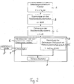
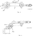
- the Fig. 3 shows that for detecting the loading moments of the robot rocker in a movement thereof (and the following robot elements) about the vertical axis A1, a strain gauge 8 on one side (the right or left side of the robot rocker 5 is arranged.
- the shows Fig. 4 to arrange for the detection of the reaction or loading moments of a movement about the first horizontal axis A2 a corresponding strain gauge 8 on the top (or on the underside) of the rocker 5.
- the Fig. 5 to 7 show concrete embodiments of the method according to the invention and a robot according to the invention with moving parts as well as the monitoring of the machine or the robot 1 by means of detection of the physical parameter material tension. Furthermore, in the Fig. 5 schematically a person 9 shown.
- a robot arm 6 hits from above, as in FIG Fig. 5 shown, on the shoulder of a person or he strikes from above on another object, so there are increased bending moments in the robot arm 6 and thus material stresses in this, by means of measuring strips 8 on the robot arm 6, in particular by on the bottom and on the top the arm arranged measuring strip 8 can be measured.
- suitable transducers such as in particular strain gauges or photoconductor-based transducers.
- the sensors detecting the resulting material stresses provide a constant image of the structural load during operation of the robot.
- the measured values obtained can be further processed and used in a number of ways, in particular online for monitoring and backup purposes, in order to permanently compare the measured values with predetermined reference values or limit values in order to ensure safety of the human-machine system by movements, namely speeds Accelerations, are kept within a tolerable range and / or abutment of a robot part against a man a stopped success.
- a reference curve R for a given movement of the robot or a robot part.
- the reference curve R is assigned a tolerable range as the reference corridor S.
- the shows Fig. 4 a trace M, which shows the actual location of the robot part in an operation over time.
- the measurement curve M moves out of the reference corridor S and thus indicates an impermissible movement or collision with unexpected measurement values. This can be effected, for example, a shutdown of the robot.
Description
Die Erfindung betrifft ein Verfahren zum Überwachen von beweglichen Teilen eines Industrieroboters sowie ein Industrieroboter mit beweglichen Teilen. Zur Realisierung eines sogenannten "Sicheren Roboters" sind folgende Maßnahmen bekannt:
- Limitierung der Achsgeschwindigkeit durch softwaremäßige Begrenzung;
- Limitierung der Geschwindigkeiten durch Begrenzung der Zwischenkreisspannung;
- Überwachung der Geschwindigkeit und/oder der Position über mehrere redundante Überwachungskanäle;
- Kollisionsüberwachung durch Überwachung der Antriebsmomente über die Motorströme;
- Kollisionsüberwachung durch separate Sensorik, z.B. zur Feststellung der Annäherung an Hindernisse (kapazitiv, induktiv, Ultraschall, visuell) oder von Berührungskräften (Druckmessmatten mit verschiedenen physikalischen Prinzipien);
- Ausschluss bestimmter Teile des Arbeitsraums durch mechanische Anschläge oder durch Software.
- Limitation of the axis speed due to software limitations;
- Limiting the speeds by limiting the intermediate circuit voltage;
- Monitoring the speed and / or the position over several redundant monitoring channels;
- Collision monitoring by monitoring the drive torques via the motor currents;
- Collision monitoring by means of separate sensors, eg for determining the approach to obstacles (capacitive, inductive, ultrasound, visual) or of contact forces (pressure measuring mats with different physical principles);
- Exclusion of certain parts of the workspace due to mechanical stops or software.
Die genannten Maßnahmen sind zum Teil als alleinige Maßnahmen nicht sicher, sondern nur in Verbindung mit mindestens einem weiteren Überwachungskanal, sie sind zum Teil aufwendig. In der Regel wird daher durch Mehrkanaligkeit, d.h. Überwachung und Heranziehung mehrerer Messungen eine hinreichende Redundanz vorgesehen. Darüber hinaus beinhaltet auch eine redundante Überwachung bisher, dass identische oder verwandte Messgrößen lediglich durch zwei oder mehrere Sensoren als Messwerte erfasst und die (gemessenen) Messwerte über getrennte Kanäle übertragen und verarbeitet werden, so dass lediglich Fehler der Erfassung, Übertragung und Verarbeitung ausgeschaltet werden konnten, nicht aber der erfassten Messgrößen oder physikalischen Größen selbst.The measures mentioned are partly unsafe as sole measures, but only in conjunction with at least one further monitoring channel, they are sometimes expensive. As a rule, therefore, multichannelism, i. Monitoring and use of multiple measurements provided sufficient redundancy. In addition, redundant monitoring has hitherto also involved identical or related measured variables only being detected as measured values by two or more sensors and the measured values being transmitted and processed via separate channels, so that only errors of acquisition, transmission and processing could be eliminated , but not the acquired measured quantities or physical quantities themselves.
In der
Der Erfindung liegt die Aufgabe einer Verbesserung der Überwachung eines Industrieroboters, zur Erhöhung der Sicherheit.The invention has the object of improving the monitoring of an industrial robot to increase safety.
Erfindungsgemäß wird die genannte Aufgabe mit einem Verfahren der eingangs genannten Art gelöst, welches dadurch gekennzeichnet ist, dass Messwerte mindestens zweier unterschiedlicher Messgrößen erfasst und zumindest einer dieser Messwerte derart zu einem ersten Messergebnis verarbeitet wird, dass es mit dem Messwert der anderen Messgröße oder einem aufgrund dieses Messwertes gewonnenen zweiten Messergebnis vergleichbar ist, dass das erste Messergebnis mit dem Messwert der anderen Messgröße oder dem aufgrund dieses Messwertes gewonnenen zweiten Messergebnis verglichen wird und dass ein das Vergleichsergebnis charakterisierende Signal bereitgestellt wird.According to the invention, the stated object is achieved by a method of the type mentioned in the introduction, which is characterized in that measured values of at least two different measured variables are detected and at least one of these Measured values are processed to a first measurement result such that it is comparable to the measured value of the other measured variable or a second measurement result obtained on the basis of this measured value, that the first measurement result is compared with the measured value of the other measured variable or the second measured result obtained on the basis of this measured value and a signal characterizing the comparison result is provided.
Zur Lösung ist weiterhin ein Industrieroboter vorgesehen, ausgestaltet durch zwei Messeinrichtungen zur Erfassung unterschiedlicher Messgrößen als Messwerte an den beweglichen Teilen des Industrieroboters , mindestens eine Verarbeitungseinheit für zumindest einen der Messwerte der Messgrößen zur Verarbeitung dieses Messwertes in ein mit dem anderen Messwert der anderen Messgröße oder einem aus diesem Messwert gewonnenen zweiten Messergebnis vergleichbaren ersten Messergebnis und durch eine Vergleichseinheit zum Vergleichen des ersten Messergebnisses mit dem Messwert der anderen Messgröße oder einem aufgrund dieses Messwertes gewonnenen zweiten Messergebnisses.An industrial robot is furthermore provided for the solution, configured by two measuring devices for detecting different measured variables as measured values on the moving parts of the industrial robot, at least one processing unit for at least one of the measured values of the measured variables for processing this measured value into one with the other measured value of the other measured variable or From this measured value obtained second measurement result comparable first measurement result and by a comparison unit for comparing the first measurement result with the measured value of the other measured variable or a second measurement result obtained on the basis of this measured value.
Messgröße ist die zu messende physikalische Größe, Messwert das unmittelbare Ergebnis eines Sensors und gegebenenfalls Wandlers, Messergebnis das Ergebnis einer rechnerischen, insbesondere elektronischen Verarbeitung eines Messwerts, insbesondere um einen Ausgangswert mit dem Messwert oder einem von diesem abgeleiteten Messergebnis einer anderen physikalischen Größe zu erhalten.The measured variable is the physical quantity to be measured, the measured value is the direct result of a sensor and, if appropriate, transducer, the result of a mathematical, in particular electronic processing of a measured value, in particular to obtain an output value with the measured value or a measurement result derived therefrom of another physical variable.
Durch die Erfindung werden unterschiedliche oder diversitäre physikalische Messgrößen zur redundanten Überwachung eines Roboters herangezogen und es werden damit diversitäre Messsignale oder -werte zur Verfügung gestellt. Hierdurch wird eine bessere redundante und damit sichere Überwachung eines Industrieroboters ermöglicht, vor allem dahingehend, dass der Roboter generell oder situationsabhängig vorgegebene Geschwindigkeiten nicht überschreitet, was zur Begrenzung des Nachlaufweges bei Stop und zur Begrenzung der kinetischen Energie wichtig ist, dass der Roboter weiterhin vorgegebene Beschleunigungswerte nicht überschreitet, was zur Vermeidung unkontrollierter Bewegungszustände bei Störung in der Regelung wichtig ist und schließlich dass Kollisionen mit Hindernissen sicher erkannt werden.By the invention are different or diverse physical measured variables are used for the redundant monitoring of a robot and thus diversified measuring signals or values are made available. This will provide better redundant and thus secure monitoring of an industrial robot, in particular in that the robot generally or depending on the situation does not exceed predetermined speeds, which is important for limiting the tracking distance at stop and to limit the kinetic energy that the robot continues to exceed predetermined acceleration values, which helps to avoid uncontrolled motion states Disturbance in the regulation is important and finally that collisions with obstacles are reliably detected.
In äußerst bevorzugter Ausgestaltung ist dabei vorgesehen, dass beispielsweise zusätzlich zur Überwachung der Bewegung eines Roboters durch Motorstrommessungen vorgesehen ist, dass als zumindest eine Messgröße Materialspannungen an Teilen des Roboters gemessen werden bzw. durch Messeinrichtungen zur Bestimmung von Materialspannungen.In an extremely preferred embodiment, it is provided that, for example, in addition to monitoring the movement of a robot by means of motor current measurements, material tensions on parts of the robot are measured as at least one measured quantity or by measuring devices for determining material tensions.
Insbesondere wesentlich ist, dass durch diese Messung von Materialspannungen bzw. der Ausbildung eines Roboters derart, dass an ihm Materialspannungen gemessen werden, gerade hierdurch ein zusätzlicher diversitärer Mess- und Verarbeitungskanal zur Verfügung gestellt wird, dessen Messsignal oder -wert keine Abhängigkeiten von korrespondierenden Werten in der Robotersteuerung, wie beispielsweise der Materialstreumessung hat, so dass störende Einflüsse nicht zu systematisch gleichen oder ähnlichen Messfehlern in allen diversitären Mess- und Verarbeitungskanälen führen. Darüber hinaus kann der aus der Materialspannung gewonnene Messwert auch zusätzlich für andere Zwecke eingesetzt werden.In particular, it is essential that an additional diversified measuring and processing channel is made available by this measurement of material stresses or the formation of a robot such that material stresses are measured on it, whose measurement signal or value does not depend on corresponding values in the robot control, such as the material scattering measurement has, so that disturbing influences do not lead to systematically the same or similar measurement errors in all diverse measurement and processing channels. In addition, the measured value obtained from the material tension can additionally be used for other purposes.
Insbesondere ermöglicht die erfindungsgemäße Überwachung von Materialspannungen indirekt die Überwachung von Reaktionsmomenten und Kräften als Ergebnis von Kollisionen, Beschleunigungen und Bewegungsgeschwindigkeiten (Zentrifugalkraft, Corioliskraft),die zu Belastung der Roboterstruktur und damit zu den zu messenden Materialspannungen führen.In particular, the monitoring of material stresses according to the invention makes it possible indirectly to monitor reaction moments and forces as a result of collisions, accelerations and movement speeds (centrifugal force, Coriolis force), which lead to load of the robot structure and thus to the material stresses to be measured.
In bevorzugter Weise werden Materialspannungen an mehreren Punkten der Roboterstruktur gemessen, wobei vorzugsweise entsprechende Messwertaufnehmer an mindestens zwei Seiten eines Roboterteils , wie Schwinge oder Roboterarm, angebracht sind, vorzugsweise aber an zwei zu einander gebrachten Seiten: Ober- bzw. Unterseite und rechte bzw. linke Seite.Preferably, material tensions are measured at a plurality of points of the robot structure, wherein preferably corresponding transducers are mounted on at least two sides of a robot part, such as rocker or robot arm, but preferably on two sides brought to one another: top and bottom and right and left, respectively Page.
In bevorzugter Ausgestaltung des erfindungsgemäßen Verfahrens ist dabei vorgesehen, dass die Materialspannungen mittels mindestens eines Messwertaufnehmers gemessen werden, wobei insbesondere Materialspannungen mittels eines Dehnungsmessstreifens gemessen werden oder aber Materialspannungen mittels eines lichtleiterbasierten Aufnehmers gemessen werden. Ein erfindungsgemäßer Roboter, ist in Weiterbildung derart ausgestaltet, dass die Einrichtungen zur Bestimmung von Materialverspannungen als Messwertaufnehmer ausgebildet sind, wobei wiederum insbesondere Einrichtungen zur Bestimmung von Materialspannungen als Dehnungsmessstreifen ausgebildet sind oder Einrichtungen zur Bestimmung von Materialspannung als piezoelektrische oder auch lichtleiterbasierte Aufnehmer ausgebildet sind. Es ist dabei grundsätzlich möglich, verschiedene Arten von Messerwertaufnehmern einzusetzen, die vorgenannten also zu kombinieren.In a preferred embodiment of the method according to the invention it is provided that the material stresses are measured by means of at least one transducer, in particular material stresses are measured by means of a strain gauge or material tensions are measured by means of a photoconductor-based transducer. A robot according to the invention is configured in such a way that the devices for determining material stresses are designed as transducers, again in particular devices for determining material tensions are designed as strain gauges or means for determining material stress are designed as piezoelectric or photoconductor-based transducers. It is basically possible to use different types of Messerwertaufnehmern, so to combine the above.
Da der Verlauf der zu messenden Messgröße und damit der durch Messung erhaltenen Messwerte, insbesondere von Materialspannungen, durch die Überlagerung von Kräften und Momenten sehr komplex sein kann, erfolgt die Auswertung der Sensorinformation vorzugsweise durch Vergleich mit Referenzverläufen, wobei sich derartige Referenzverläufe einerseits synthetisch durch Berechnung über ein entsprechendes mathematisches Modell oder durch Aufzeichnung der realen Messwerte unter bekannten Bedingungen (ohne Störeinflüsse) erzeugen lassen. In weiterer bevorzugter Ausgestaltung ist daher vorgesehen, dass aktuelle Messwerte oder Messergebnisse mit Referenzwerten verglichen werden, wobei insbesondere aktuelle Messwerte oder Messergebnisse mit Referenzwerten unter Berücksichtigung von Toleranzen gemessen werden und/oder Toleranzen durch Bildung eines Referenzkorridors zu einer Referenzkurve berücksichtigt werden. Weichen die Messwerte oder Messergebnisse von der entsprechenden Referenzkurve stärker als zulässig ab, so kann auf ein unvorhergesehenes Ereignis, z.B. eine Kollision mit dem Bediener geschlossen werden. Die zulässige Grenze der Abweichung wird durch ein Toleranzband (Referenzkorridor) definiert.Since the course of the measured variable to be measured and thus the measured values obtained by measurement, in particular of material stresses, by the superposition of forces and moments can be very complex, the evaluation of the sensor information is preferably carried out by comparison with reference curves, wherein such reference curves can be generated synthetically by calculation over a corresponding mathematical model or by recording the real measured values under known conditions (without interference). In a further preferred refinement, it is therefore provided that current measured values or measurement results are compared with reference values, wherein in particular current measured values or measurement results with reference values taking into account tolerances are measured and / or tolerances are taken into account by forming a reference corridor to a reference curve. If the measured values or measurement results deviate more than permissible from the corresponding reference curve, it is possible to conclude an unforeseen event, eg a collision with the operator. The permissible limit of deviation is defined by a tolerance band (reference corridor).
Dabei kann in bevorzugter Weise vorgesehen sein, dass bei Abweichungen von erwarteten Messwerten oder Messergebnissen ein Stillsetzen des Roboters erfolgt, wobei insbesondere, wie schon vorstehend angedeutet, die Messung von MaterialSpannungen zur Überwachung der Bewegung des Roboters zusammen mit der Messung anderer Überwachungsgrößen als redundante Überwachung erfolgt.In this case, it can be provided in a preferred manner that in the case of deviations from expected measured values or measurement results, the robot is shut down, wherein in particular, as already indicated above, the measurement of material tensions for monitoring the movement of the robot takes place together with the measurement of other monitoring variables as redundant monitoring ,
Eine Weiterbildung des erfindungsgemäßen Roboters sieht vor, dass auf mindestens zwei Flächen eines Roboterteils jeweils mindestens eine Einrichtung zur Bestimmung von Materialspannungen angeordnet ist.A refinement of the robot according to the invention provides that at least one device for determining material stresses is arranged on at least two surfaces of a robot part.
In bevorzugter Ausgestaltung ist eine Überwachungseinrichtung vorgesehen, mit der mindestens eine Einrichtung zur Bestimmung von Materialspannungen an Roboterteilen verbunden ist.In a preferred embodiment, a monitoring device is provided, with the at least one device for Determination of material stresses connected to robot parts.
Die Redundanz bei der Prüfung auf unerwartete Ergebnisse wird erreicht durch gleichzeitige Auswertung der erfindungsgemäß überwachten Materialspannungen zusammen mit mindestens einem weiteren Messkanal, wozu insbesondere herangezogen werden können über das Wegmesssystem in der Steuerung softwaremäßig ermittelte Positionen und/oder Geschwindigkeiten oder aber Motormomente, die über Stromsensoren in den Antriebsverstärkern gemessen werden.The redundancy in the test for unexpected results is achieved by simultaneous evaluation of the inventively monitored material stresses together with at least one other measuring channel, which can be used in particular via the position measuring system in the control software determined positions and / or speeds or engine torque, via current sensors in the drive amplifiers are measured.
Meldet keiner der redundanten Messkanäle eine Überschreitung des Toleranzbandes, darf auf Störungsfreiheit geschlossen werden. Meldet mindestens einer der Messkanäle eine Überschreitung, wird durch eine sichere Logik der Roboter gestoppt und in einen sicheren Zustand gebracht, indem Bremsen geschlossen und Antriebe energielos geschaltet werden.If none of the redundant measuring channels indicates that the tolerance band has been exceeded, then freedom from interference may be assumed. If at least one of the measuring channels indicates an overshoot, the robot is stopped by a safe logic and brought to a safe state by braking is closed and drives are energized.
Weitere Vorteile und Merkmale der Erfindung ergeben sich aus den Ansprüchen und aus der nachfolgenden Beschreibung, in der Ausführungsbeispiele der Erfindung unter Bezugnahme auf die Zeichnungen im einzelnen erläutert sind. Dabei zeigt:
- Fig. 1
- ein Blockdiagramm zur Überwachung der Bewegungen eines Roboters.
- Fig. 2
- ein Diagramm zur Erfassung und Bewertung von Materialspannungen an einem Roboterteil.
- Fig. 3
- ein konkretes Ausgestaltungsbeispiels zur Erfassung von Materialspannungen an einem Roboter aufgrund einer Bewegung um die A1-Achse.
- Fig. 4
- ein konkretes Ausgestaltungsbeispiels zur Erfassung von Materialspannungen an einem Roboter aufgrund einer Bewegung um die A3-Achse.
- Fig. 5
- einen Roboter, dessen Roboterarm in Kontakt mit der Schulter einer Person gelangt;
- Fig. 6
- einen Roboter mit schematischer Darstellung des Reaktionsmoments auf die Beschleunigung der Achse A3;
- Fig. 7
- einen Roboter mit schematischer Darstellung der bei Bewegung um die vertikale Achse A1 auftretenden Zentrifugal- und Corioliskräfte;
- Fig. 1
- a block diagram for monitoring the movements of a robot.
- Fig. 2
- a diagram for the detection and evaluation of material stresses on a robot part.
- Fig. 3
- a concrete embodiment example for detecting material stresses on a robot due to a movement around the A1 axis.
- Fig. 4
- a concrete embodiment example for detecting material stresses on a robot due to a movement about the A3 axis.
- Fig. 5
- a robot whose robot arm comes into contact with a person's shoulder;
- Fig. 6
- a robot with a schematic representation of the reaction torque on the acceleration of the axis A3;
- Fig. 7
- a robot with a schematic representation of the centrifugal and Coriolis forces occurring when moving about the vertical axis A1;
Die
Bei Betrieb eines Roboters können in Teilen desselben Kräfte und Momente auftreten, die zu Materialspannungen innerhalb der Teile des Roboters führen, welche über geeignete Einrichtungen, wie Dehnungsmessstreifen 8 oder auch lichtleiterbasierte Aufnehmer (nicht dargestellt) erfasst und damit auch während des Betriebs des Roboters hinsichtlich des Abweichens von vorgegebenen Wertverläufen oder von vorgegebenen oder erwarteten Wertverläufen überwacht werden können.During operation of a robot, forces and moments may occur in parts thereof, which lead to material tensions within the parts of the robot, which are detected by suitable devices, such as
Der Industrieroboter der
Es ist ein Roboter 1 dargestellt und zusätzlich als Blockschaltbild eine Überwachungseinrichtung 11. Die Überwachungseinrichtung 11 weist eine Überwachungseinheit 12 zur Überwachung von Dehnungen der Roboterstruktur, eine Überwachungseinheit 13 zur Überwachung der Position von Roboterteilen unter Berücksichtigung des Zeitablaufs und damit der Geschwindigkeit sowie schließlich eine Überwachungseinheit 14 zur Überwachung des Motorstroms aus den Umrichtern 3 und damit des Antriebsmoments auf.The
In einer Vergleichseinheit 15 im Rahmen der Überwachungsvorrichtung 11 werden die durch die Einheiten 12, 13, 14 gemessenen Messwerte oder Messergebnisse mit Modellwerten eines Modells 16 verglichen. Weichen die gemessenen Werte von vorgegebenen Werten bzw. einem vorgegebenen Verlauf ab, so erfolgt über eine Schalteinrichtung 17 ein sicheres Abschalten des Roboters.In a
Die
Bei beispielsweise einem Roboter entstehen durch Beschleunigungen und auch Kollisionen (Abbremsen, negative Beschleunigung) als Reaktion hierauf Reaktions-Belastungsmomente M gemäß ![]()
![]()
Dieses Belastungsmoment führt gemäß ![]()
![]()
Diese Spannungen bewirken wiederum nach dem Hookschen Gesetz ![]()
![]()
Dehnungen ε am Roboterteil, wobei E der Elastizitätsmodul ist, die durch Dehnungsmessstreifen erfasst bzw. gemessen werden können (Schritt C).Strains ε on the robot part, where E is the modulus of elasticity, which can be detected or measured by strain gauges (step C).
Die Messwerte der Dehnungen ε können nun derart weiterverarbeitet werden, dass die Messwerte der Dehnungs- und damit Spannungsmessungen mit anderen Messwerten anderer Messgrößen, beispielsweise Motorstrommesswerten vergleichbar sind (Schritt E). In einem weiteren Schritt F erfolgt dann ein Vergleich mit einer solchen weiteren Messgröße F', und, in dem Falle, dass beide einen Fehler, eine gefährliche Situation oder dergleichen anzeigen, ein sicheres Abschalten (Schritt G). Zusätzlich oder alternativ kann vorgesehen sein, dass unmittelbar eine Bewertung der Dehnungen, d.h. der Vergleich mit einem Referenzdehnungsverlauf erfolgt (Schritt E') und, wenn der Vergleich ergibt, dass das Messergebnis aus dem Referenzdehnungsverlauf oder Referenzkorridor herausfällt, dann ebenfalls ein sicheres Abschalten erfolgt (Schritt G).The measured values of the strains ε can now be further processed such that the measured values of the strain and thus voltage measurements are comparable to other measured values of other measured variables, for example motor current measured values (step E). In a further step F, a comparison is then made with such a further measured variable F ', and, in the event that both indicate an error, a dangerous situation or the like, a safe shutdown (step G). Additionally or alternatively may be provided be that directly an evaluation of the strains, ie, the comparison with a reference strain curve takes place (step E ') and, if the comparison shows that the measurement result from the reference strain curve or reference corridor falls out, then also a safe shutdown takes place (step G).
Die
Demgegenüber zeigt die
Die
Schlägt beispielsweise ein Roboterarm 6 von oben, wie in
Wie schon unter Bezug auf ![]()
![]()
Anhand der ![]()
![]()
![]()
![]()
Die die hierdurch entstehenden Materialspannungen erfassenden Sensoren liefern bei Betrieb des Roboters ein ständiges Abbild der Strukturbelastung. Die gewonnenen Messwerte können in mehrfacher Weise weiterverarbeitet und genutzt werden, insbesondere online zu Überwachungs- und Sicherungszwecken, um die gemessenen Werte permanent mit vorgegebenen Richtwerten oder Grenzwerten zu vergleichen um damit eine Sicherheit des Mensch-Maschine-Systems zu gewährleisten, indem Bewegungen, nämlich Geschwindigkeiten bzw. Beschleunigungen, in einem tolerierbaren Bereich gehalten werden und/oder bei Anstoßen eines Roboterteils gegen einen Menschen einen stillgesetzten Erfolg.The sensors detecting the resulting material stresses provide a constant image of the structural load during operation of the robot. The measured values obtained can be further processed and used in a number of ways, in particular online for monitoring and backup purposes, in order to permanently compare the measured values with predetermined reference values or limit values in order to ensure safety of the human-machine system by movements, namely speeds Accelerations, are kept within a tolerable range and / or abutment of a robot part against a man a stopped success.
So zeigt die
- 11
- Industrieroboterindustrial robots
- 22
- Robotersockelrobot base
- 33
- Umrichterinverter
- 44
- Schwingewing
- 55
- Roboterschwingerobot rocker
- 66
- Roboterarmrobot arm
- 77
- Roboterhandrobotic hand
- 88th
- DehnungsmessstreifenStrain gauges
- 99
- Personperson
- 1111
- Überwachungseinrichtungmonitoring device
- 1212
- Überwachungseinheitmonitoring unit
- 1313
- Überwachungseinheitmonitoring unit
- 1414
- Überwachungseinheitmonitoring unit
- 1515
- Vergleichseinheitcomparing unit
- 1616
- Modellmodel
- 1717
- Schalteinrichtungswitching device
- MM
- Messkurvemeasured curve
- RR
- Referenzkurvereference curve
- SS
- Referenz KorridorReference corridor
- XX
- BereichArea
Claims (20)
- Method for monitoring movable parts of an industrial robot (1), in which the measurement values of two different measured quantities are detected and at least one of these measurement values is processed into a first measurement result, characterised in that the measurement value is processed into a first measurement result such that it is comparable with the measurement value of the other measured quantity or a second measurement result obtained on the basis of said measurement value, in that the first measurement result is compared with the measurement value of the other measured quantity or the second measurement result obtained on the basis of said measurement value and in that a signal characterising the comparison result is provided.
- Method according to claim 1, characterised in that material stresses on parts of the machine are measured as at least one measured quantity.
- Method according to claim 2, characterised in that the material stresses are measured by means of at least one measurement transducer (8).
- Method according to claim 2 or 3, characterised in that the material stresses are measured by means of a stress gauge (8).
- Method according to any one of claims 2 or 3, characterised in that the material stresses are measured by means of piezoelectric or fibre optic-based sensors.
- Method according to any one of claims 2 to 5, characterised in that the material stresses are measured by means of measurement transducers (8) positioned on at least two surfaces of a robot part.
- Method according to any one of the preceding claims, characterised in that current measured values of measured quantities or measurement results are compared with reference values.
- Method according to claim 7, characterised in that current measurement values of measured quantities and/or measurement results are compared with reference values, whilst taking account of tolerances.
- Method according to claim 8, characterised in that tolerances are taken into account by forming a reference corridor to a reference curve.
- Method according to any one of the preceding claims, characterised in that in the case of divergences from expected measurement values and/or measurement results the robot is stopped.
- Industrial robot (1), comprising two measuring devices for determining different measured quantities as measurement values on movable parts of the industrial robot, characterised by at least one processing unit (12, 13, 14) for at least one of the measurement values of the measured quantities for processing said measurement value into a first measurement result comparable with the other measurement value of the other measured quantity or a second measurement result obtained on the basis of said measurement value and by a comparison unit (15) for comparing the first measurement result with at least the measurement value of the other measured quantity or a second measurement result obtained on the basis of said measurement value.
- Industrial robot according to claim 11, characterised by measuring devices for determining material stresses.
- Industrial robot according to claim 12, characterised in that the devices for determining material stresses are designed in the form of measurement transducers.
- Industrial robot according to claim 12 or 13, characterised in that the devices for determining material stress are designed in the form of strain gauges (8).
- Industrial robot according to any one of claims 12 to 14, characterised in that the devices for determining material stress are designed as fibre optic-based sensors.
- Industrial robot according to any one of claims 12 to 15, characterised in that in each case at least one device for determining material stresses is arranged on at least two surfaces of a robot part.
- Industrial robot according to any one of claims 12 to 16, characterised by a monitoring device (11) to which at least one device is connected for determining material stresses on machine parts of the industrial robot.
- Industrial robot according to claim 16 or 17, characterised in that the monitoring device (11) comprises units for monitoring at least elongations of the machine structure of the industrial robot and a further measured quantity.
- Industrial robot according to any one of claims 16 to 18, characterised in that the monitoring device (11) comprises a comparison device (15) for comparing current measurement values and/or measurement results with predetermined models for robot movements (16).
- Industrial robot according to any one of claims 18 to 19, characterised in that the monitoring device (11) comprises a switching device (17) for switching off the industrial robot.
Applications Claiming Priority (2)
| Application Number | Priority Date | Filing Date | Title |
|---|---|---|---|
| DE10304019A DE10304019A1 (en) | 2003-02-01 | 2003-02-01 | Method for monitoring a machine and such a machine, in particular a robot |
| DE10304019 | 2003-02-01 |
Publications (4)
| Publication Number | Publication Date |
|---|---|
| EP1445075A2 EP1445075A2 (en) | 2004-08-11 |
| EP1445075A3 EP1445075A3 (en) | 2008-04-09 |
| EP1445075B1 true EP1445075B1 (en) | 2017-04-12 |
| EP1445075B2 EP1445075B2 (en) | 2022-01-12 |
Family
ID=32603084
Family Applications (1)
| Application Number | Title | Priority Date | Filing Date |
|---|---|---|---|
| EP04001285.8A Expired - Lifetime EP1445075B2 (en) | 2003-02-01 | 2004-01-22 | Method for monitoring a robot and robot with monitoring means |
Country Status (4)
| Country | Link |
|---|---|
| US (1) | US7086293B2 (en) |
| EP (1) | EP1445075B2 (en) |
| DE (1) | DE10304019A1 (en) |
| DK (1) | DK1445075T3 (en) |
Cited By (1)
| Publication number | Priority date | Publication date | Assignee | Title |
|---|---|---|---|---|
| WO2022120820A1 (en) * | 2020-12-11 | 2022-06-16 | Abb Schweiz Ag | Robot control system, robot control method, and robot |
Families Citing this family (38)
| Publication number | Priority date | Publication date | Assignee | Title |
|---|---|---|---|---|
| JP4513568B2 (en) * | 2002-07-18 | 2010-07-28 | 株式会社安川電機 | Robot controller |
| DE10304019A1 (en) * | 2003-02-01 | 2004-11-04 | Kuka Roboter Gmbh | Method for monitoring a machine and such a machine, in particular a robot |
| AT502286B1 (en) * | 2004-09-15 | 2008-09-15 | Wfl Millturn Tech Gmbh & Co Kg | PROCEDURE FOR COLLISION PREVENTION |
| EP1764192B1 (en) * | 2005-09-16 | 2009-11-25 | Abb Ab | An industrial robot with sensor means in the region of a tool flange |
| EP1854425A1 (en) | 2006-05-11 | 2007-11-14 | BrainLAB AG | Position determination for medical devices with redundant position measurement and weighting to prioritise measurements |
| EP1857229B1 (en) * | 2006-05-16 | 2009-07-15 | Abb Ab | A control system for an industrial robot |
| DE102006055849A1 (en) * | 2006-11-27 | 2008-05-29 | Innotec Gmbh | Method for the safety-related disconnection of movement processes in the event of a collision |
| EP1932629B1 (en) * | 2006-12-11 | 2019-04-24 | ABB Research Ltd. | A method and a control system for monitoring the condition of an industrial robot |
| EP1955830B1 (en) | 2007-02-06 | 2014-04-09 | Abb Research Ltd. | A method and a control system for monitoring the condition of an industrial robot |
| DE102007006708A1 (en) | 2007-02-10 | 2008-08-14 | Abb Research Ltd. | Method for securing a handling device |
| DE102007050232B4 (en) * | 2007-10-20 | 2024-05-02 | Deutsches Zentrum für Luft- und Raumfahrt e.V. | Handling robot and method for controlling a handling robot |
| DE102007060682B4 (en) * | 2007-12-17 | 2015-08-20 | Kuka Roboter Gmbh | Method and device for model-based control of a manipulator |
| DE102007063099A1 (en) * | 2007-12-28 | 2009-07-02 | Kuka Roboter Gmbh | Robot and method for monitoring the moments on such |
| JP2009297810A (en) * | 2008-06-11 | 2009-12-24 | Panasonic Corp | Posture control device of manipulator and posture control method thereof |
| DE102008054312A1 (en) | 2008-11-03 | 2010-05-06 | Kuka Roboter Gmbh | Method and device for reliable detection of a kinematic variable of a manipulator |
| DE102010029186A1 (en) | 2010-05-20 | 2011-11-24 | Kuka Roboter Gmbh | Measuring device and robot |
| DE102010033248A1 (en) | 2010-08-03 | 2012-01-19 | Kuka Laboratories Gmbh | Manipulator e.g. six-axis articulated robot, monitoring method, involves determining driving power size and model energy parameter of manipulator, where determined driving power size and model energy parameter are compared |
| US8781629B2 (en) | 2010-09-22 | 2014-07-15 | Toyota Motor Engineering & Manufacturing North America, Inc. | Human-robot interface apparatuses and methods of controlling robots |
| DE102011106321A1 (en) * | 2011-07-01 | 2013-01-03 | Kuka Laboratories Gmbh | Method and control means for controlling a robot |
| JP5912683B2 (en) * | 2012-03-07 | 2016-04-27 | 株式会社神戸製鋼所 | System having motor drive structure, program used for motor drive structure system, and welded article manufacturing method |
| CN104781792B (en) * | 2012-11-07 | 2016-06-29 | Abb技术有限公司 | Judge redundant device unit and the method for fault in industrial control system, industrial control system and include the industrial system of redundant device unit |
| DE102013010290A1 (en) * | 2013-06-19 | 2014-12-24 | Kuka Laboratories Gmbh | Monitoring a kinematic redundant robot |
| US9884426B2 (en) | 2013-06-27 | 2018-02-06 | De-Sta-Co Europe Gmbh | Boom utilized in a geometric end effector system |
| US9446517B2 (en) * | 2013-10-17 | 2016-09-20 | Intuitive Surgical Operations, Inc. | Fault reaction, fault isolation, and graceful degradation in a robotic system |
| DE202013105036U1 (en) * | 2013-11-08 | 2015-02-10 | Daimler Ag | detector |
| JP2016064479A (en) * | 2014-09-25 | 2016-04-28 | ファナック株式会社 | Robot control device |
| EP3020514B1 (en) * | 2014-11-17 | 2023-10-11 | KRONES Aktiengesellschaft | Handling device and method for handling items |
| DE102014223419A1 (en) * | 2014-11-17 | 2016-05-19 | Krones Aktiengesellschaft | Method and device for handling and / or manipulating articles such as containers or piece goods |
| DE102015211348A1 (en) * | 2015-06-19 | 2016-12-22 | Krones Aktiengesellschaft | Handling device and method for handling articles |
| DE102015212171B3 (en) | 2015-06-30 | 2016-06-30 | Kuka Roboter Gmbh | Method for controlling a manipulator system |
| WO2017070872A1 (en) * | 2015-10-28 | 2017-05-04 | 西门子公司 | Method and apparatus for abnormality detection |
| WO2018112028A1 (en) | 2016-12-16 | 2018-06-21 | Mako Surgical Corp. | Techniques for detecting errors or loss of accuracy in a surgical robotic system |
| DE102016015237B4 (en) * | 2016-12-21 | 2019-02-21 | Kuka Roboter Gmbh | Safe determination of axis positions and / or velocities of a robot |
| WO2018133964A1 (en) | 2017-01-18 | 2018-07-26 | Siemens Wind Power A/S | Standardized platform arrangement of a wind turbine |
| DE102018204184A1 (en) * | 2018-03-19 | 2019-09-19 | Leoni Kabel Gmbh | Method for monitoring a supply system of a robot |
| US11386289B2 (en) * | 2019-11-05 | 2022-07-12 | Elementary Robotics, Inc. | Systems and methods for robot-aided product inspection |
| CN113043269B (en) * | 2019-12-27 | 2024-04-05 | 深圳慧智星晨科技有限公司 | Robot contact force observation system based on robot model |
| EP4172582A1 (en) * | 2020-06-24 | 2023-05-03 | Abb Schweiz Ag | A system for testing the padding of a robotic manipulator |
Family Cites Families (18)
| Publication number | Priority date | Publication date | Assignee | Title |
|---|---|---|---|---|
| DE3244738A1 (en) * | 1982-12-03 | 1984-06-07 | Uraca Pumpenfabrik GmbH & Co KG, 7432 Urach | Device for monitoring valves in an intermittently operating machine |
| JPS59108691A (en) * | 1982-12-13 | 1984-06-23 | 株式会社日立製作所 | Control system of balancer |
| DE3407618A1 (en) * | 1984-03-01 | 1985-09-12 | Klaus Prof. Dr.-Ing. 4006 Erkrath Brankamp | Device for determining a force occurring between two machine parts which can be moved against one another |
| CA1233222A (en) * | 1984-03-09 | 1988-02-23 | Nobuhiko Onda | Movable apparatus driving system |
| JPS61226287A (en) * | 1985-03-07 | 1986-10-08 | エプシロン テクノロジー インコーポレーテツド | Device and method for treating workpiece |
| US4715773A (en) * | 1985-06-04 | 1987-12-29 | Clemson University | Method and apparatus for repositioning a mislocated object with a robot hand |
| US4783107A (en) * | 1985-06-04 | 1988-11-08 | Clemson University | Method and apparatus for controlling impact force during rapid robotic acquisition of object |
| FR2589238B1 (en) * | 1985-10-25 | 1987-11-20 | Commissariat Energie Atomique | SENSOR FOR EFFORT AND TORQUE MEASUREMENT AND APPLICATIONS OF SUCH A SENSOR TO A PROBE AND TO A GRIPPING DEVICE |
| DE3624941C2 (en) * | 1986-07-23 | 1995-01-19 | Loedige Maschbau Gmbh Geb | Process for monitoring operating conditions of continuously operating machines and mixers operating thereafter |
| US5081593A (en) * | 1989-08-16 | 1992-01-14 | Megamation Incorporated | Method and apparatus for monitoring and controlling linear motor robot apparatus and the like |
| JPH03178788A (en) * | 1989-12-06 | 1991-08-02 | Hitachi Ltd | Control method for manipulator |
| JPH05269684A (en) * | 1992-03-23 | 1993-10-19 | Mitsubishi Electric Corp | Industrial robot device |
| US5440935A (en) * | 1993-03-18 | 1995-08-15 | Mts Systems Corporation | Apparatus for combining transducer output signals |
| DE4432759A1 (en) * | 1994-09-14 | 1996-03-21 | Gemac Ges Fuer Mikroelektronik | Safety control and monitoring module e.g. for CNC machines and industrial robots |
| JPH08118284A (en) * | 1994-10-26 | 1996-05-14 | Toshiba Corp | Industrial robot |
| JPH1158278A (en) * | 1997-08-25 | 1999-03-02 | Yaskawa Electric Corp | Control device for robot |
| DE10020174A1 (en) * | 2000-04-25 | 2001-11-15 | Bosch Gmbh Robert | Automatic monitoring arrangement of rolling bearings in machines and tools |
| DE10304019A1 (en) * | 2003-02-01 | 2004-11-04 | Kuka Roboter Gmbh | Method for monitoring a machine and such a machine, in particular a robot |
-
2003
- 2003-02-01 DE DE10304019A patent/DE10304019A1/en not_active Ceased
-
2004
- 2004-01-22 DK DK04001285.8T patent/DK1445075T3/en active
- 2004-01-22 EP EP04001285.8A patent/EP1445075B2/en not_active Expired - Lifetime
- 2004-01-28 US US10/766,769 patent/US7086293B2/en not_active Expired - Lifetime
Non-Patent Citations (4)
| Title |
|---|
| D.G. LUENBERGER: "Observing the state of a linear system", IEEE TRANSACTION ON MILITARY ELECTRONICS, vol. 8, 1964, pages 74 - 80, XP055453534 |
| H.-B. KUNTZE ET AL.: "On A SMART STRUCTURE VARIABLE SUPERVISORY CONTROL CONCEPT FOR HUMANOID ROBOTS", INT. CONF. ON HUMANOID ROBOTS KARLSRUHE, CONFERENCE DOCUMENTATION, January 2003 (2003-01-01), XP055453528 |
| K. SUITA ET AL.: "A failure-to-safety ''Kyozon'' system with simple contact detection and stop capabilities for safe human -autonomous robot coexistence", PROC. IEEE INT. CONF. ON ROBOTICS AND AUTOMATION, 1995, pages 3089 - 3096, XP000731687 |
| M. L. VISINSKY ET AL.: "Robotic fault detection and fault tolerance: A survey", RELIABILTY ENGINEERING AND SYSTEM SAFETY, vol. 46, 1994, pages 139 - 158, XP055108909 |
Cited By (1)
| Publication number | Priority date | Publication date | Assignee | Title |
|---|---|---|---|---|
| WO2022120820A1 (en) * | 2020-12-11 | 2022-06-16 | Abb Schweiz Ag | Robot control system, robot control method, and robot |
Also Published As
| Publication number | Publication date |
|---|---|
| EP1445075A3 (en) | 2008-04-09 |
| US7086293B2 (en) | 2006-08-08 |
| DE10304019A1 (en) | 2004-11-04 |
| US20040260481A1 (en) | 2004-12-23 |
| DK1445075T3 (en) | 2017-07-24 |
| EP1445075B2 (en) | 2022-01-12 |
| EP1445075A2 (en) | 2004-08-11 |
Similar Documents
| Publication | Publication Date | Title |
|---|---|---|
| EP1445075B1 (en) | Method for monitoring a robot and robot with monitoring means | |
| EP2347309B1 (en) | Method and device for reliably capturing a kinematic parameter of a manipulator | |
| DE2628701C2 (en) | ||
| EP0391174B2 (en) | Arrangement and method to detect physical parameters of an elevator | |
| EP2807103B1 (en) | Safety device and control method for a lift system | |
| EP2628575B1 (en) | Method for determining a torque and industrial robot | |
| DE102010044644B4 (en) | Method for collision detection for a drive unit | |
| EP1600833A2 (en) | Method and apparatus for operating a machine, like a mulit-axis industrial robot | |
| WO2016184451A1 (en) | Method and device for open-loop/closed-loop control of an actuator-driven robot joint | |
| DE102015224641A1 (en) | A method for detecting a collision of a robot arm with an object and robot with a robot arm | |
| DE3911391A1 (en) | METHOD FOR DETECTING THE PHYSICAL CHARACTERISTICS OF AN ELEVATOR | |
| EP2388565B1 (en) | Measuring device and robot | |
| DE102017115800B4 (en) | Arrangement for an articulated robot and method for determining a positioning of a receptacle for an end effector of a articulated robot | |
| EP3439834B1 (en) | Cartesian control of a boom tip of a large manipulator, in particular a concrete pump | |
| EP0985989B1 (en) | Method and device for improving the dynamic behaviour of a robot | |
| DE102018104082B4 (en) | Robotic system | |
| DE102020126209A1 (en) | ROBOT | |
| EP3298377B1 (en) | Test pendulum arrangement and method for operating a test pendulum arrangement | |
| EP4124789B1 (en) | Securing of a movable part of a machine | |
| DE102012108418A1 (en) | Device for enabling secure collaboration between human and selective complaint articulated arm robot, used in e.g. industrial automation field, has robotic controller having control unit connected in series with servo axle amplifiers | |
| EP3734380B1 (en) | Method and device for monitoring an acceleration of an axis of a multi-axis kinematic | |
| DE102019114463B4 (en) | Overload and breakage monitoring method and system for an aircraft high-lift system | |
| DE102019129721B3 (en) | Brake device system, test pendulum assembly for performing neck certifications, and method for operating a test pendulum assembly | |
| EP3839153A1 (en) | Method for calibrating a position sensor | |
| EP2647557B1 (en) | Industrial truck with a drawbar pivoting about a horizontal axis |
Legal Events
| Date | Code | Title | Description |
|---|---|---|---|
| PUAI | Public reference made under article 153(3) epc to a published international application that has entered the european phase |
Free format text: ORIGINAL CODE: 0009012 |
|
| AK | Designated contracting states |
Kind code of ref document: A2 Designated state(s): AT BE BG CH CY CZ DE DK EE ES FI FR GB GR HU IE IT LI LU MC NL PT RO SE SI SK TR |
|
| AX | Request for extension of the european patent |
Extension state: AL LT LV MK |
|
| PUAL | Search report despatched |
Free format text: ORIGINAL CODE: 0009013 |
|
| AK | Designated contracting states |
Kind code of ref document: A3 Designated state(s): AT BE BG CH CY CZ DE DK EE ES FI FR GB GR HU IE IT LI LU MC NL PT RO SE SI SK TR |
|
| AX | Request for extension of the european patent |
Extension state: AL LT LV MK |
|
| 17P | Request for examination filed |
Effective date: 20080905 |
|
| AKX | Designation fees paid |
Designated state(s): AT BE BG CH CY CZ DE DK EE ES FI FR GB GR HU IE IT LI LU MC NL PT RO SE SI SK TR |
|
| 17Q | First examination report despatched |
Effective date: 20110609 |
|
| GRAP | Despatch of communication of intention to grant a patent |
Free format text: ORIGINAL CODE: EPIDOSNIGR1 |
|
| STAA | Information on the status of an ep patent application or granted ep patent |
Free format text: STATUS: GRANT OF PATENT IS INTENDED |
|
| INTG | Intention to grant announced |
Effective date: 20170109 |
|
| GRAS | Grant fee paid |
Free format text: ORIGINAL CODE: EPIDOSNIGR3 |
|
| GRAA | (expected) grant |
Free format text: ORIGINAL CODE: 0009210 |
|
| STAA | Information on the status of an ep patent application or granted ep patent |
Free format text: STATUS: THE PATENT HAS BEEN GRANTED |
|
| AK | Designated contracting states |
Kind code of ref document: B1 Designated state(s): AT BE BG CH CY CZ DE DK EE ES FI FR GB GR HU IE IT LI LU MC NL PT RO SE SI SK TR |
|
| REG | Reference to a national code |
Ref country code: GB Ref legal event code: FG4D Free format text: NOT ENGLISH |
|
| REG | Reference to a national code |
Ref country code: CH Ref legal event code: EP |
|
| REG | Reference to a national code |
Ref country code: IE Ref legal event code: FG4D Free format text: LANGUAGE OF EP DOCUMENT: GERMAN |
|
| REG | Reference to a national code |
Ref country code: AT Ref legal event code: REF Ref document number: 883388 Country of ref document: AT Kind code of ref document: T Effective date: 20170515 |
|
| REG | Reference to a national code |
Ref country code: DE Ref legal event code: R096 Ref document number: 502004015500 Country of ref document: DE |
|
| REG | Reference to a national code |
Ref country code: CH Ref legal event code: NV Representative=s name: FIAMMENGHI-FIAMMENGHI, CH Ref country code: CH Ref legal event code: PCOW Free format text: NEW ADDRESS: ZUGSPITZSTRASSE 140, 86165 AUGSBURG (DE) |
|
| REG | Reference to a national code |
Ref country code: SE Ref legal event code: TRGR |
|
| REG | Reference to a national code |
Ref country code: DK Ref legal event code: T3 Effective date: 20170719 |
|
| REG | Reference to a national code |
Ref country code: NL Ref legal event code: MP Effective date: 20170412 |
|
| PG25 | Lapsed in a contracting state [announced via postgrant information from national office to epo] |
Ref country code: NL Free format text: LAPSE BECAUSE OF FAILURE TO SUBMIT A TRANSLATION OF THE DESCRIPTION OR TO PAY THE FEE WITHIN THE PRESCRIBED TIME-LIMIT Effective date: 20170412 |
|
| PG25 | Lapsed in a contracting state [announced via postgrant information from national office to epo] |
Ref country code: FI Free format text: LAPSE BECAUSE OF FAILURE TO SUBMIT A TRANSLATION OF THE DESCRIPTION OR TO PAY THE FEE WITHIN THE PRESCRIBED TIME-LIMIT Effective date: 20170412 Ref country code: GR Free format text: LAPSE BECAUSE OF FAILURE TO SUBMIT A TRANSLATION OF THE DESCRIPTION OR TO PAY THE FEE WITHIN THE PRESCRIBED TIME-LIMIT Effective date: 20170713 Ref country code: ES Free format text: LAPSE BECAUSE OF FAILURE TO SUBMIT A TRANSLATION OF THE DESCRIPTION OR TO PAY THE FEE WITHIN THE PRESCRIBED TIME-LIMIT Effective date: 20170412 |
|
| PG25 | Lapsed in a contracting state [announced via postgrant information from national office to epo] |
Ref country code: BG Free format text: LAPSE BECAUSE OF FAILURE TO SUBMIT A TRANSLATION OF THE DESCRIPTION OR TO PAY THE FEE WITHIN THE PRESCRIBED TIME-LIMIT Effective date: 20170712 |
|
| REG | Reference to a national code |
Ref country code: FR Ref legal event code: PLFP Year of fee payment: 15 |
|
| REG | Reference to a national code |
Ref country code: DE Ref legal event code: R026 Ref document number: 502004015500 Country of ref document: DE |
|
| PLBI | Opposition filed |
Free format text: ORIGINAL CODE: 0009260 |
|
| PLAX | Notice of opposition and request to file observation + time limit sent |
Free format text: ORIGINAL CODE: EPIDOSNOBS2 |
|
| PG25 | Lapsed in a contracting state [announced via postgrant information from national office to epo] |
Ref country code: RO Free format text: LAPSE BECAUSE OF FAILURE TO SUBMIT A TRANSLATION OF THE DESCRIPTION OR TO PAY THE FEE WITHIN THE PRESCRIBED TIME-LIMIT Effective date: 20170412 Ref country code: EE Free format text: LAPSE BECAUSE OF FAILURE TO SUBMIT A TRANSLATION OF THE DESCRIPTION OR TO PAY THE FEE WITHIN THE PRESCRIBED TIME-LIMIT Effective date: 20170412 Ref country code: SK Free format text: LAPSE BECAUSE OF FAILURE TO SUBMIT A TRANSLATION OF THE DESCRIPTION OR TO PAY THE FEE WITHIN THE PRESCRIBED TIME-LIMIT Effective date: 20170412 Ref country code: CZ Free format text: LAPSE BECAUSE OF FAILURE TO SUBMIT A TRANSLATION OF THE DESCRIPTION OR TO PAY THE FEE WITHIN THE PRESCRIBED TIME-LIMIT Effective date: 20170412 |
|
| 26 | Opposition filed |
Opponent name: FRANKA EMIKA GMBH Effective date: 20180112 |
|
| PLBB | Reply of patent proprietor to notice(s) of opposition received |
Free format text: ORIGINAL CODE: EPIDOSNOBS3 |
|
| PG25 | Lapsed in a contracting state [announced via postgrant information from national office to epo] |
Ref country code: SI Free format text: LAPSE BECAUSE OF FAILURE TO SUBMIT A TRANSLATION OF THE DESCRIPTION OR TO PAY THE FEE WITHIN THE PRESCRIBED TIME-LIMIT Effective date: 20170412 |
|
| RAP2 | Party data changed (patent owner data changed or rights of a patent transferred) |
Owner name: KUKA DEUTSCHLAND GMBH |
|
| PG25 | Lapsed in a contracting state [announced via postgrant information from national office to epo] |
Ref country code: LU Free format text: LAPSE BECAUSE OF NON-PAYMENT OF DUE FEES Effective date: 20180122 |
|
| REG | Reference to a national code |
Ref country code: IE Ref legal event code: MM4A |
|
| REG | Reference to a national code |
Ref country code: BE Ref legal event code: MM Effective date: 20180131 |
|
| PG25 | Lapsed in a contracting state [announced via postgrant information from national office to epo] |
Ref country code: BE Free format text: LAPSE BECAUSE OF NON-PAYMENT OF DUE FEES Effective date: 20180131 |
|
| PG25 | Lapsed in a contracting state [announced via postgrant information from national office to epo] |
Ref country code: IE Free format text: LAPSE BECAUSE OF NON-PAYMENT OF DUE FEES Effective date: 20180122 |
|
| REG | Reference to a national code |
Ref country code: AT Ref legal event code: MM01 Ref document number: 883388 Country of ref document: AT Kind code of ref document: T Effective date: 20180122 |
|
| PG25 | Lapsed in a contracting state [announced via postgrant information from national office to epo] |
Ref country code: AT Free format text: LAPSE BECAUSE OF NON-PAYMENT OF DUE FEES Effective date: 20180122 |
|
| PG25 | Lapsed in a contracting state [announced via postgrant information from national office to epo] |
Ref country code: MC Free format text: LAPSE BECAUSE OF FAILURE TO SUBMIT A TRANSLATION OF THE DESCRIPTION OR TO PAY THE FEE WITHIN THE PRESCRIBED TIME-LIMIT Effective date: 20170412 |
|
| APBM | Appeal reference recorded |
Free format text: ORIGINAL CODE: EPIDOSNREFNO |
|
| APBP | Date of receipt of notice of appeal recorded |
Free format text: ORIGINAL CODE: EPIDOSNNOA2O |
|
| APAH | Appeal reference modified |
Free format text: ORIGINAL CODE: EPIDOSCREFNO |
|
| APAW | Appeal reference deleted |
Free format text: ORIGINAL CODE: EPIDOSDREFNO |
|
| APBQ | Date of receipt of statement of grounds of appeal recorded |
Free format text: ORIGINAL CODE: EPIDOSNNOA3O |
|
| APBQ | Date of receipt of statement of grounds of appeal recorded |
Free format text: ORIGINAL CODE: EPIDOSNNOA3O |
|
| PG25 | Lapsed in a contracting state [announced via postgrant information from national office to epo] |
Ref country code: TR Free format text: LAPSE BECAUSE OF FAILURE TO SUBMIT A TRANSLATION OF THE DESCRIPTION OR TO PAY THE FEE WITHIN THE PRESCRIBED TIME-LIMIT Effective date: 20170412 |
|
| PG25 | Lapsed in a contracting state [announced via postgrant information from national office to epo] |
Ref country code: PT Free format text: LAPSE BECAUSE OF FAILURE TO SUBMIT A TRANSLATION OF THE DESCRIPTION OR TO PAY THE FEE WITHIN THE PRESCRIBED TIME-LIMIT Effective date: 20170412 Ref country code: HU Free format text: LAPSE BECAUSE OF FAILURE TO SUBMIT A TRANSLATION OF THE DESCRIPTION OR TO PAY THE FEE WITHIN THE PRESCRIBED TIME-LIMIT; INVALID AB INITIO Effective date: 20040122 |
|
| PG25 | Lapsed in a contracting state [announced via postgrant information from national office to epo] |
Ref country code: CY Free format text: LAPSE BECAUSE OF FAILURE TO SUBMIT A TRANSLATION OF THE DESCRIPTION OR TO PAY THE FEE WITHIN THE PRESCRIBED TIME-LIMIT Effective date: 20170412 |
|
| REG | Reference to a national code |
Ref country code: DE Ref legal event code: R082 Ref document number: 502004015500 Country of ref document: DE Representative=s name: KILBURN & STRODE LLP, NL |
|
| APBU | Appeal procedure closed |
Free format text: ORIGINAL CODE: EPIDOSNNOA9O |
|
| PUAH | Patent maintained in amended form |
Free format text: ORIGINAL CODE: 0009272 |
|
| STAA | Information on the status of an ep patent application or granted ep patent |
Free format text: STATUS: PATENT MAINTAINED AS AMENDED |
|
| 27A | Patent maintained in amended form |
Effective date: 20220112 |
|
| AK | Designated contracting states |
Kind code of ref document: B2 Designated state(s): AT BE BG CH CY CZ DE DK EE ES FI FR GB GR HU IE IT LI LU MC NL PT RO SE SI SK TR |
|
| REG | Reference to a national code |
Ref country code: DE Ref legal event code: R102 Ref document number: 502004015500 Country of ref document: DE |
|
| PGFP | Annual fee paid to national office [announced via postgrant information from national office to epo] |
Ref country code: SE Payment date: 20211210 Year of fee payment: 19 |
|
| PGFP | Annual fee paid to national office [announced via postgrant information from national office to epo] |
Ref country code: DK Payment date: 20220110 Year of fee payment: 19 |
|
| REG | Reference to a national code |
Ref country code: SE Ref legal event code: NAV |
|
| PGFP | Annual fee paid to national office [announced via postgrant information from national office to epo] |
Ref country code: IT Payment date: 20211213 Year of fee payment: 19 |
|
| PG25 | Lapsed in a contracting state [announced via postgrant information from national office to epo] |
Ref country code: DK Free format text: LAPSE BECAUSE OF FAILURE TO SUBMIT A TRANSLATION OF THE DESCRIPTION OR TO PAY THE FEE WITHIN THE PRESCRIBED TIME-LIMIT Effective date: 20220112 |
|
| PGFP | Annual fee paid to national office [announced via postgrant information from national office to epo] |
Ref country code: GB Payment date: 20221201 Year of fee payment: 20 Ref country code: FR Payment date: 20221208 Year of fee payment: 20 |
|
| PGFP | Annual fee paid to national office [announced via postgrant information from national office to epo] |
Ref country code: CH Payment date: 20230106 Year of fee payment: 20 |
|
| PGFP | Annual fee paid to national office [announced via postgrant information from national office to epo] |
Ref country code: DE Payment date: 20221130 Year of fee payment: 20 |
|
| P01 | Opt-out of the competence of the unified patent court (upc) registered |
Effective date: 20230528 |
|
| REG | Reference to a national code |
Ref country code: DE Ref legal event code: R071 Ref document number: 502004015500 Country of ref document: DE |
|
| PG25 | Lapsed in a contracting state [announced via postgrant information from national office to epo] |
Ref country code: IT Free format text: LAPSE BECAUSE OF NON-PAYMENT OF DUE FEES Effective date: 20230122 |
|
| REG | Reference to a national code |
Ref country code: CH Ref legal event code: PL |
|
| REG | Reference to a national code |
Ref country code: GB Ref legal event code: PE20 Expiry date: 20240121 |