EP1443692A2 - Method and apparatus for determining an operating condition in a communications system using antenna arrays - Google Patents
Method and apparatus for determining an operating condition in a communications system using antenna arrays Download PDFInfo
- Publication number
- EP1443692A2 EP1443692A2 EP04010769A EP04010769A EP1443692A2 EP 1443692 A2 EP1443692 A2 EP 1443692A2 EP 04010769 A EP04010769 A EP 04010769A EP 04010769 A EP04010769 A EP 04010769A EP 1443692 A2 EP1443692 A2 EP 1443692A2
- Authority
- EP
- European Patent Office
- Prior art keywords
- environment
- uplink
- ber
- uplink signals
- antenna array
- Prior art date
- Legal status (The legal status is an assumption and is not a legal conclusion. Google has not performed a legal analysis and makes no representation as to the accuracy of the status listed.)
- Granted
Links
Images


Classifications
-
- H—ELECTRICITY
- H04—ELECTRIC COMMUNICATION TECHNIQUE
- H04B—TRANSMISSION
- H04B7/00—Radio transmission systems, i.e. using radiation field
- H04B7/02—Diversity systems; Multi-antenna system, i.e. transmission or reception using multiple antennas
- H04B7/04—Diversity systems; Multi-antenna system, i.e. transmission or reception using multiple antennas using two or more spaced independent antennas
- H04B7/08—Diversity systems; Multi-antenna system, i.e. transmission or reception using multiple antennas using two or more spaced independent antennas at the receiving station
-
- H—ELECTRICITY
- H04—ELECTRIC COMMUNICATION TECHNIQUE
- H04B—TRANSMISSION
- H04B7/00—Radio transmission systems, i.e. using radiation field
- H04B7/02—Diversity systems; Multi-antenna system, i.e. transmission or reception using multiple antennas
- H04B7/04—Diversity systems; Multi-antenna system, i.e. transmission or reception using multiple antennas using two or more spaced independent antennas
- H04B7/08—Diversity systems; Multi-antenna system, i.e. transmission or reception using multiple antennas using two or more spaced independent antennas at the receiving station
- H04B7/0837—Diversity systems; Multi-antenna system, i.e. transmission or reception using multiple antennas using two or more spaced independent antennas at the receiving station using pre-detection combining
- H04B7/0842—Weighted combining
- H04B7/086—Weighted combining using weights depending on external parameters, e.g. direction of arrival [DOA], predetermined weights or beamforming
-
- H—ELECTRICITY
- H04—ELECTRIC COMMUNICATION TECHNIQUE
- H04B—TRANSMISSION
- H04B17/00—Monitoring; Testing
- H04B17/30—Monitoring; Testing of propagation channels
- H04B17/309—Measuring or estimating channel quality parameters
- H04B17/336—Signal-to-interference ratio [SIR] or carrier-to-interference ratio [CIR]
-
- H—ELECTRICITY
- H04—ELECTRIC COMMUNICATION TECHNIQUE
- H04B—TRANSMISSION
- H04B17/00—Monitoring; Testing
- H04B17/30—Monitoring; Testing of propagation channels
- H04B17/391—Modelling the propagation channel
-
- H—ELECTRICITY
- H04—ELECTRIC COMMUNICATION TECHNIQUE
- H04B—TRANSMISSION
- H04B7/00—Radio transmission systems, i.e. using radiation field
- H04B7/02—Diversity systems; Multi-antenna system, i.e. transmission or reception using multiple antennas
- H04B7/04—Diversity systems; Multi-antenna system, i.e. transmission or reception using multiple antennas using two or more spaced independent antennas
- H04B7/08—Diversity systems; Multi-antenna system, i.e. transmission or reception using multiple antennas using two or more spaced independent antennas at the receiving station
- H04B7/0837—Diversity systems; Multi-antenna system, i.e. transmission or reception using multiple antennas using two or more spaced independent antennas at the receiving station using pre-detection combining
- H04B7/0842—Weighted combining
- H04B7/0848—Joint weighting
-
- H—ELECTRICITY
- H04—ELECTRIC COMMUNICATION TECHNIQUE
- H04L—TRANSMISSION OF DIGITAL INFORMATION, e.g. TELEGRAPHIC COMMUNICATION
- H04L1/00—Arrangements for detecting or preventing errors in the information received
- H04L1/20—Arrangements for detecting or preventing errors in the information received using signal quality detector
- H04L1/203—Details of error rate determination, e.g. BER, FER or WER
-
- H—ELECTRICITY
- H04—ELECTRIC COMMUNICATION TECHNIQUE
- H04B—TRANSMISSION
- H04B7/00—Radio transmission systems, i.e. using radiation field
- H04B7/02—Diversity systems; Multi-antenna system, i.e. transmission or reception using multiple antennas
- H04B7/04—Diversity systems; Multi-antenna system, i.e. transmission or reception using multiple antennas using two or more spaced independent antennas
- H04B7/08—Diversity systems; Multi-antenna system, i.e. transmission or reception using multiple antennas using two or more spaced independent antennas at the receiving station
- H04B7/0837—Diversity systems; Multi-antenna system, i.e. transmission or reception using multiple antennas using two or more spaced independent antennas at the receiving station using pre-detection combining
- H04B7/0842—Weighted combining
-
- H—ELECTRICITY
- H04—ELECTRIC COMMUNICATION TECHNIQUE
- H04B—TRANSMISSION
- H04B7/00—Radio transmission systems, i.e. using radiation field
- H04B7/02—Diversity systems; Multi-antenna system, i.e. transmission or reception using multiple antennas
- H04B7/04—Diversity systems; Multi-antenna system, i.e. transmission or reception using multiple antennas using two or more spaced independent antennas
- H04B7/08—Diversity systems; Multi-antenna system, i.e. transmission or reception using multiple antennas using two or more spaced independent antennas at the receiving station
- H04B7/0837—Diversity systems; Multi-antenna system, i.e. transmission or reception using multiple antennas using two or more spaced independent antennas at the receiving station using pre-detection combining
- H04B7/0842—Weighted combining
- H04B7/0848—Joint weighting
- H04B7/0854—Joint weighting using error minimizing algorithms, e.g. minimum mean squared error [MMSE], "cross-correlation" or matrix inversion
-
- H—ELECTRICITY
- H04—ELECTRIC COMMUNICATION TECHNIQUE
- H04B—TRANSMISSION
- H04B7/00—Radio transmission systems, i.e. using radiation field
- H04B7/02—Diversity systems; Multi-antenna system, i.e. transmission or reception using multiple antennas
- H04B7/04—Diversity systems; Multi-antenna system, i.e. transmission or reception using multiple antennas using two or more spaced independent antennas
- H04B7/08—Diversity systems; Multi-antenna system, i.e. transmission or reception using multiple antennas using two or more spaced independent antennas at the receiving station
- H04B7/0837—Diversity systems; Multi-antenna system, i.e. transmission or reception using multiple antennas using two or more spaced independent antennas at the receiving station using pre-detection combining
- H04B7/0842—Weighted combining
- H04B7/0848—Joint weighting
- H04B7/0857—Joint weighting using maximum ratio combining techniques, e.g. signal-to- interference ratio [SIR], received signal strenght indication [RSS]
Definitions
- the present invention relates generally to communications systems and, more specifically, the present invention relates to wireless communications systems employing antenna arrays.
- Antenna arrays may be used in communications systems that transmit and/or receive radio frequency signals.
- Antenna arrays typically include a number of antennas that are spatially separated and may be employed in a number of different wireless applications including radio communications systems, cellular systems, television broadcasting, point to point systems, paging systems, medical applications or the like.
- antenna arrays in such systems often provide antenna performance improvements over the use of a single element antenna. These antenna performance improvements may include for received signals improved signal to noise ratio and interference rejection. Antenna performance improvements for transmitted signals may include improved directionality and hence less power towards other co-channel users, security and reduced transmit power requirements. Antenna arrays may be used for signal reception only, for signal transmission or for both signal reception and transmission.
- a typical application of antenna array systems is in a wireless communication system.
- Examples include a cellular communication system and a wireless local loop system.
- Such wireless communications systems typically include one or more communications stations, generally called based stations, each communicating with its subscriber units, also called remote terminals and handsets.
- the remote terminal is typically mobile, while in wireless local loop systems, the remote unit is typically in a fixed location.
- the antenna array is typically at the base station, but may also be employed at a user terminal. Communication from the remote terminal to the base station is typically called the uplink and communication from the base station to the remote terminal is typically called the downlink.
- TDD time division duplex
- FDD frequency division duplex
- the behavior of the signals in the uplink and downlink communication channels between the base station and remote terminal are different. The differences are more apparent as the channels have more multipath components.
- scattering and/or reflections caused by, for example, buildings or the like result in amplitude and phase changes and/or multipath components in the communication signals.
- Multipath components behave differently for different frequencies and a communication signal arriving at an antenna array changes with the frequency. Accordingly, the performance of a wireless communications system is impacted by the presence of scatterers in the environment.
- Another factor that impacts wireless communication system performance is the presence of multiple remote terminals utilizing the same frequency or channel at the same time in the environment. As the number of separate sources or remote terminals utilizing the same frequency increases, the amount of interference in the communications channel also increases.
- the present invention provides a method of characterizing an environment, comprising: receiving uplink signals from a plurality of antenna array elements; calculating a signal to noise ratio in response to the uplink signals received from the plurality of antenna array elements; measuring a bit error rate (BER) in response the uplink signals received from the plurality of antenna array elements; determining an expected BER in response to the signal to noise ratio; and selecting a high interference environment estimation if the measured BER is a BER threshold amount greater than the expected BER.
- BER bit error rate
- an environment estimation apparatus includes a plurality of antenna elements and a receiver coupled to receive uplink signals from the plurality of antenna elements.
- the apparatus also includes a signal processor coupled to receive the uplink signals to select an estimation of an environment responsive to the uplink signals received from the plurality of antenna elements. Additional features and benefits of the present invention will become apparent from the detailed description, figures and claims set forth below.
- FIG. 1 is a block diagram illustration of one embodiment of a base station in accordance with the teachings of the present invention.
- FIG. 2 is a block diagram illustration of one embodiment of a base station operating in a low clutter environment in accordance with the teachings of the present invention.
- FIG. 3 is a block diagram illustration of one embodiment of a base station operating in a high clutter and low interference environment in accordance with the teachings of the present invention.
- Figure 4 is a block diagram illustration of one embodiment of a base station operating in a high clutter and high interference environment in accordance with the teachings of the present invention.
- Figure 5 is a flow diagram illustrating a method for identifying a low or high clutter environment.
- Figure 6 is a flow diagram illustrating another method for identifying a low or high clutter environment.
- Figure 7 is a flow diagram illustrating a method for identifying a low or high interference environment.
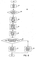
- Figure 8 is a flow diagram illustrating an embodiment of a method for identifying a low or high interference environment in accordance with the teachings of the present invention.
- a base station in a wireless communication system is provided with the ability to estimate an environment or condition in which the wireless communication system is operating.
- the base station includes an antenna array having a plurality of antenna elements. Uplink communication signals are received by the antenna elements in the antenna array and processing is performed on the uplink communication signals to estimate whether the base station is operating in a low clutter or high clutter environment. In addition, processing is performed in one embodiment on the uplink communication signals when in a high clutter environment to estimate whether the base station is operating in a low interference or high interference environment.
- FIG. 1 is a block diagram illustration of one embodiment of a base station 10 1 of a wireless communication system in accordance with the teachings of the present invention.
- base station 101 includes an antenna array 103 having a plurality of antenna elements 105 and 107. It is appreciated that although antenna array 103 is illustrated having two antenna elements 105 and 107 in Figure 1 for explanation purposes, antenna array 103 may include more than two antenna elements in accordance with the teachings of the present invention.
- uplink communication signals 117 are received by the antenna elements 105 and 107 of antenna array 103. In one embodiment, the uplink communication signals 117 are received from one or more remote terminals of a wireless communication system.
- a receiver 109 is coupled to receive uplink communication signals 117 from the antenna elements 105 and 107 of antenna array 103.
- signal processor 111 is coupled to receiver 109 to receive the uplink communication signals 117.
- storage 113 is coupled to receiver 109 to store the uplink communication signals 117 received by receiver 109 and signal processor 111 is coupled to storage 113 to receive the stored communication signals.
- storage 113 is a machine-readable medium on which software instructions that may be executed by signal processor 111 are stored.
- signal processor 111 processes the received uplink communication signals 117 and generates an environment estimate 115 in response to the received uplink communication signals 117.
- environment estimate 115 may be an estimate of a low or high clutter environment and/or an estimate of a low or high interference environment.
- FIG. 2 is a block diagram illustration of one embodiment of a base station 201 operating in a low clutter environment in accordance with the teachings of the present invention.
- a low clutter environment corresponds to an environment in which there are relatively few scatterers or the like, which may cause multipath components.
- Such an environment may be found in for example a suburban environment, which may be characterized by one or two storeyed buildings. In some cases, there may be a line of sight between the base station and the remote terminal.
- base station 201 includes an antenna array 203 receiving uplink communication signals 217 from remote terminal 219.
- base station 201 may be part of a cellular base station or the like and remote terminal may be a mobile unit that is part of a cellular phone or the like.
- the present invention is not limited to any particular type of wireless application, such as for example cellular systems, but may be utilized in various types of wireless systems and applications employing antenna arrays.
- the present invention is useful in spatial division multiple access systems (SDMA) or other types of systems in which adaptive arrays may be employed.
- SDMA spatial division multiple access systems
- one embodiment of the present invention maybe utilized in time division duplex (TDD) or especially frequency division duplex (FDD) communication systems and/or in conjunction with other wireless architectures.
- TDD time division duplex
- FDD frequency division duplex
- each or a combination of the various elements of embodiments of the present invention may be implemented in hardware, software, or a combination thereof.
- base station 201 receives uplink communication signals 217 through antenna array 203.
- Base station 201 processes the uplink signals 217 and generates an environment estimate 215, which in Figure 2 is an estimate of a low clutter environment.
- FIG. 3 is a block diagram illustration of one embodiment of a base station 301 operating in a high clutter and low interference environment in accordance with the teachings of the present invention.
- a high clutter environment corresponds to an environment in which there is a relatively large amount of scatterers or the like, which may cause multipath components.
- One example of such an environment may be an urban environment, which may be characterized by tall buildings and the propagation environment is relatively harsh. Line of sight propagation conditions are generally absent in high clutter environments.
- Urban or high clutter environment propagation channels usually include multiple propagation paths and do not include a dominant path, as in suburban environments. Accordingly, there is typically a significant angle of arrival spread of incoming uplink signals in high clutter environments.
- a low interference environment corresponds to an environment in which there are relatively few sources or remote terminals utilizing the same frequency or channel at the same time.
- base station 301 includes an antenna array 303 receiving uplink communication signals 317 from remote terminal 319.
- antenna array 303 receives uplink communication signals 317 from remote terminal 319.
- the relatively large number of scatterers introduce many multipath components in the uplink communication signals 317.
- the environment illustrated in Figure 3 is a high clutter environment.
- the example illustrated in Figure 3 shows relatively few remote terminals, one of which is illustrated with remote terminal 319, and therefore the depicted environment is an example of a low interference environment.
- base station 301 receives uplink communication signals 317 through antenna array 303.
- Base station 301 processes the uplink signals 317 and generates an environment estimate 315, which in Figure 3 is an estimate of a high clutter environment In one embodiment, if a high clutter environment is estimated, an estimation of whether the environment is low or high interference is provided. In the embodiment depicted in Figure 3, environmental estimate 315 includes an estimate of a low interference environment.
- FIG 4 is a block diagram illustration of one embodiment of a base station 401 operating in a high clutter and high interference environment in accordance with the teachings of the present invention.
- a high interference environment corresponds to an environment in which there is a relatively large number of sources or remote terminals utilizing the same frequency or channel at the same time.
- One example of such an environment may be an environment in which there are many wireless phone users using the same channel such as for example in a busy downtown or airport environment.
- base station 401 includes an antenna array 403 receiving uplink communication signals 417 from many remote terminals, including remote terminals 419 and 421.
- the relatively large number of scatterers introduce many multipath components in the uplink communication signals 417.
- the environment illustrated in Figure 4 is a high clutter environment
- the example illustrated in Figure 4 a relatively large number of remote terminals, two of which are illustrated with remote terminals 419 and 421, and.therefore the depicted environment is an example of a high interference environment.
- base station 401 receives uplink communication signals 417 through antenna array 403.
- Base station 401 processes the uplink signals 417 and generates an environment estimate 415, which in Figure 4 is an estimate of a high clutter and high interference environment.
- Figure 5 is a flow diagram 501 illustration of a method for identifying a low or high clutter environment.
- uplink signals are received by for example the plurality of antenna elements 105 and 107 of antenna array 103 of Figure 1.
- the uplink signals are provided to receiver 103 and are then provided to signal processor 111.
- the uplink signals are stored in storage 113 and are then provided to signal processor 111.
- uplink signals are received directly from receiver 109.
- Block 505 shows that an uplink spatial signature is then estimated.
- r zs provides an estimate of the uplink. signature, â t .
- r zs is equal to the uplink spatial signature where r zs is (Z H s] Mx1 , a correlation vector ofZ and s.
- Z represents a matrix representing the received uplink signal
- s represents a reference signal
- M is the number of elements in then antenna array
- H represents a Hermitian transpose.
- AOA angle of arrival
- AOA estimation techniques that may be utilized in accordance with the teachings of the present invention include the Delay and Sum method, Capon's method, Multiple Signal Classification (MUSIC) and Estimation of Signal Parameters via Rotational Invariance Techniques (ESPRIT).
- MUSIC Multiple Signal Classification
- ESPRIT Estimation of Signal Parameters via Rotational Invariance Techniques
- the Delay and Sum method is also referred to as a classical beamformer method or Fourier method.
- the output power of the beamformer is calculated for each azimuthal angle.
- the AOA corresponding to the largest output power is declared as the source AOA. This known technique produces broad beams.
- the known MUSIC technique is a high resolution algorithm that exploits the Eigen structure of the input covariance matrix.
- MUSIC is a signal parameter estimation algorithm that estimates the number of incident signals, their AOAs, their strengths and the cross correlations between the incident signals.
- the Eigen vectors of the covariance matrix belong to either of the two orthogonal subspaces: signal subspace or noise subspace.
- the steering vector corresponding to the AOA of the signals lie in the signal subspace and hence orthogonal to the noise subspace.
- the known ESPRIT technique is another subspace technique that reduces the computation and storage requirements for MUSIC.
- ESPRIT does not require an exhaustive search or precise calibration.
- ESPRIT derives its advantages by utilizing array elements that have a structure that can be decomposed into two equal sized identical subarrays with corresponding elements of the two subarrays being displaced from one another by a fixed translational, not rotational, distance.
- the geometric uplink spatial signal â g may be calculated using the estimated dominant AOA ⁇ d with Equation 6 above.
- the dominant AOA ⁇ d corresponds to the AOA with the highest power.
- â g e j(2 ⁇ / ⁇ )( ⁇ /2)cos(90°)[0:1]
- â g [1 1]
- block 509 shows that in one embodiment, the correlation between the estimated true uplink spatial signature â t and the geometric uplink spatial signature â g is then calculated.
- the correlation between â t and â g is calculated by determining the normalized dot product between estimated uplink spatial signature â t and the geometric uplink spatial signature â g . If the correlation is greater than a low clutter threshold, then a low clutter environment estimation is selected, as shown in Figure 5 with block 511. Otherwise, a high clutter environment estimation is selected, as shown in Figure 5 with block 513.
- FIG. 6 is a flow diagram 601 illustration of another method for identifying a low or high clutter environment.
- uplink signals are received by for example base station 101.
- Block 605 shows that pairwise correlations of the uplink signals are then calculated.
- Pairwise correlations are determined by calculating the normalized dot product for of the pairwise correlations.
- block 607 shows that, the average of the pairwise correlations is then calculated. average of the absolute values of all pairwise correlations is calculated.
- Block 609 shows that the average of the pairwise correlations is then compared with a high clutter threshold. If the average is less than the high clutter threshold, then a high clutter environment estimation is selected, as shown in Figure 6 with block 611. Otherwise, a low clutter environment estimation is selected, as shown in Figure 6 with block 613. It is appreciated that the high clutter threshold is determined in one embodiment based on a number of factors including the number of antenna elements M in the antenna array.
- FIG. 7 is a flow diagram 701 illustration of a method for identifying a low or high interference environment.
- uplink signals are received by for example base station 101.
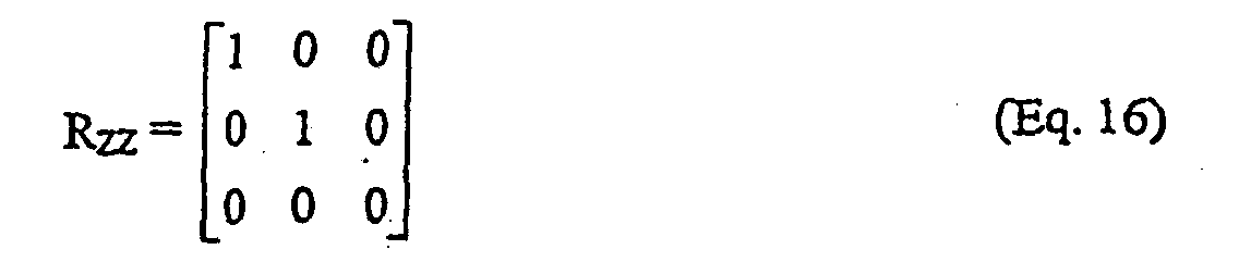
- Block 705 shows that a correlation matrix R ZZ is then calculated from the uplink signals.
- block 707 shows that the source order is then calculated from the correlation matrix R ZZ .
- the source order is an estimate of the number of users in the same frequency and time and is calculated by first determining Eigen values for R ZZ .
- the source order may be determined using well-known techniques including for example Sequential Hypothesis (SH), Minimum Descriptive Length (MDL), Akaike Information Criteria (AIC) or the like. As is known to those skilled in the art, all these techniques estimate then source order or number of sources by minimizing a log-likelihood function, where the likelihood function is the ratio of geometric mean to arithmetic mean of the Eigen values of the input correlation matrix.
- SH Sequential Hypothesis
- MDL Minimum Descriptive Length
- AIC Akaike Information Criteria
- block 709 shows that the estimated source order is then compared to a high interference threshold. If the estimated source order is greater than the high interference threshold, which in one embodiment is equal one, then a high interference environment estimation is selected, as shown in Figure 7 with block 711. Otherwise, a low interference environment estimation is selected, as shown in Figure 7 with block 713.
- FIG. 8 is a flow diagram 801 illustration of an embodiment of a method for identifying a low or high interference environment in accordance with the teachings of the present invention.
- uplink signals are received by for example base station 101 in accordance with the teachings of an embodiment of the present invention.
- a received signal strength indication (RSSI) of the uplink communications signals is then measured.
- the RSSI includes the components of S, N and I, where S represents the desired signal, N represents noise and I represents interference. If the RSSI is greater than an RSSI threshold, as shown in block 803, block 804 shows that in one embodiment, the signal to noise ratio is then calculated from the uplink communication signals.
- the noise N can then be measured from the uplink communication signals.
- block 805 shows that an expected bit error rate (BER) can then be determined in accordance with the teachings of the present invention.
- the expected BER is determined based on values predicted in advance that may for example be stored in look-up tables or the like. In particular, for a given signal to noise ratio, an expected BER can be determined. In another embodiment, the expected BER is a function of the signal to noise ratio and can therefore be derived from the signal to noise ratio.
- block 807 shows the BER is also measured from the received uplink communication signals in one embodiment of the present invention.
- Block 809 shows that in one embodiment, the measured BER is then compared to the expected BER In one embodiment, if the measured BER is greater than the expected BER by a BER threshold amount, then a high interference environment estimation is selected, as shown in Figure 8 with block 811. Otherwise, a low interference environment estimation is selected, as shown in Figure 8 with block 813.
- a further aspect of the invention comprises a method of characterizing an environment, comprising:
- calculating the geometric uplink spatial signature comprises:
- finding the correlation between the estimated uplink spatial signature and the geometric uplink spatial signature comprises calculating a normalized dot product of the estimated uplink spatial signature and the geometric uplink spatial signature.
- estimating the uplink spatial signature of the received uplink signals comprises calculating a correlation vector between the uplink signals received by the plurality of antenna array elements and a reference signal.
- a yet further aspect of the invention comprises a method of characterizing an environment, comprising:
- calculating said pairwise correlations of the uplink signals received by the plurality of antenna array elements comprises calculating a normalized dot product for said pairwise correlations of the uplink signals received by the plurality of antenna array elements.
- a yet further aspect of the invention comprises a method of characterizing an environment, comprising:
- estimating the source order in response to the correlation matrix comprises:
- estimating the source order in response to the correlation matrix comprises:
- estimating the source order in response to the correlation matrix comprises:
Landscapes
- Engineering & Computer Science (AREA)
- Computer Networks & Wireless Communication (AREA)
- Signal Processing (AREA)
- Physics & Mathematics (AREA)
- Electromagnetism (AREA)
- Quality & Reliability (AREA)
- Mobile Radio Communication Systems (AREA)
- Radio Transmission System (AREA)
Abstract
Description
- estimating an uplink spatial signature of the received uplink signals; and
- calculating a geometric uplink spatial signature of the received uplink signals.
Optionally, characterizing the environment based on the estimated uplink spatial
signatures comprises:
- finding a correlation between the estimated uplink spatial signature and the geometric uplink spatial signature; and
- selecting a low clutter environment estimation if the correlation between the estimated uplink spatial signature and the geometric uplink spatial signature is greater than a low clutter threshold.
Claims (3)
- A method of characterizing an environment, comprising:receiving uplink signals from a plurality of antenna array elements;calculating a signal to noise ratio in response to the uplink signals received from the plurality of antenna array elements;measuring a bit error rate (BER) in response the uplink signals received from the plurality of antenna array elements;determining an expected BER in response to the signal to noise ratio; andselecting a high interference environment estimation if the measured BER is a BER threshold amount greater than the expected BER.
- The method of claim 1 wherein calculating the signal to noise ratio in response to the uplink signals received from the plurality of antenna array elements comprises:measuring a received signal strength indication (RSSI) in response to the uplink signals received from the plurality of antenna array elements; andmeasuring noise included in the uplink signals received from the plurality of antenna array elements.
- The method of claim 2 further comprising selecting the high interference environment estimation if the measured BER is a BER threshold amount greater than the expected BER and the RSSI is greater than a RSSI threshold value.
Applications Claiming Priority (3)
| Application Number | Priority Date | Filing Date | Title |
|---|---|---|---|
| US668664 | 2000-09-22 | ||
| US09/668,664 US7460835B1 (en) | 2000-09-22 | 2000-09-22 | Method and apparatus for determining an operating condition in a communications system |
| EP01971259A EP1319276B1 (en) | 2000-09-22 | 2001-09-20 | Method and apparatus for determining an operating condition in a communications system using antenna arrays |
Related Parent Applications (2)
| Application Number | Title | Priority Date | Filing Date |
|---|---|---|---|
| EP01971259A Division EP1319276B1 (en) | 2000-09-22 | 2001-09-20 | Method and apparatus for determining an operating condition in a communications system using antenna arrays |
| EP01971259.5 Division | 2001-09-20 |
Publications (3)
| Publication Number | Publication Date |
|---|---|
| EP1443692A2 true EP1443692A2 (en) | 2004-08-04 |
| EP1443692A3 EP1443692A3 (en) | 2004-10-27 |
| EP1443692B1 EP1443692B1 (en) | 2010-11-10 |
Family
ID=24683269
Family Applications (2)
| Application Number | Title | Priority Date | Filing Date |
|---|---|---|---|
| EP01971259A Expired - Lifetime EP1319276B1 (en) | 2000-09-22 | 2001-09-20 | Method and apparatus for determining an operating condition in a communications system using antenna arrays |
| EP04010769A Expired - Lifetime EP1443692B1 (en) | 2000-09-22 | 2001-09-20 | Method and apparatus for determining an operating condition in a communications system using antenna arrays |
Family Applications Before (1)
| Application Number | Title | Priority Date | Filing Date |
|---|---|---|---|
| EP01971259A Expired - Lifetime EP1319276B1 (en) | 2000-09-22 | 2001-09-20 | Method and apparatus for determining an operating condition in a communications system using antenna arrays |
Country Status (8)
| Country | Link |
|---|---|
| US (2) | US7460835B1 (en) |
| EP (2) | EP1319276B1 (en) |
| JP (1) | JP4980548B2 (en) |
| KR (1) | KR20030034199A (en) |
| CN (1) | CN1322684C (en) |
| AU (1) | AU2001291164A (en) |
| DE (2) | DE60143454D1 (en) |
| WO (1) | WO2002025837A2 (en) |
Cited By (1)
| Publication number | Priority date | Publication date | Assignee | Title |
|---|---|---|---|---|
| CN112292840A (en) * | 2018-06-29 | 2021-01-29 | 苹果公司 | Spatial heat density reduction for millimeter wave antenna arrays |
Families Citing this family (9)
| Publication number | Priority date | Publication date | Assignee | Title |
|---|---|---|---|---|
| US8363744B2 (en) | 2001-06-10 | 2013-01-29 | Aloft Media, Llc | Method and system for robust, secure, and high-efficiency voice and packet transmission over ad-hoc, mesh, and MIMO communication networks |
| JP4309110B2 (en) * | 2002-09-27 | 2009-08-05 | パナソニック株式会社 | Adaptive antenna wireless communication device |
| JP3717913B2 (en) * | 2002-12-27 | 2005-11-16 | 三洋電機株式会社 | Wireless device |
| CN100492954C (en) * | 2003-08-20 | 2009-05-27 | 大唐移动通信设备有限公司 | Spatial Feature Extraction and Signal Direction of Arrival Estimation Method for CDMA Wireless Communication |
| CN100531011C (en) | 2005-07-04 | 2009-08-19 | 上海原动力通信科技有限公司 | Method for defining up-converter channel impact responding and multi-user united detection method |
| US8213978B1 (en) | 2005-08-29 | 2012-07-03 | At&T Mobility Ii Llc | Estimating mobile local propagation environment characteristics for wireless communications |
| US7778311B2 (en) * | 2005-10-04 | 2010-08-17 | Sirf Technology Holdings, Inc. | Bit synchronization for weak navigational satellite signals |
| US9113362B2 (en) | 2006-12-12 | 2015-08-18 | At&T Mobility Ii Llc | Method and apparatus to separate coverage limited and co-channel limited interferences |
| JP5494567B2 (en) * | 2011-05-17 | 2014-05-14 | 株式会社デンソー | Radar apparatus, inspection system, and inspection method |
Family Cites Families (18)
| Publication number | Priority date | Publication date | Assignee | Title |
|---|---|---|---|---|
| JP3046842B2 (en) | 1992-04-24 | 2000-05-29 | モトローラ・インコーポレーテッド | Method and apparatus for determining signal transmission quality level of transmission signal |
| JPH0799475A (en) * | 1993-05-14 | 1995-04-11 | Hitachi Maxell Ltd | Data communication device |
| EP0807989B1 (en) * | 1996-05-17 | 2001-06-27 | Motorola Ltd | Devices for transmitter path weights and methods therefor |
| US5886988A (en) * | 1996-10-23 | 1999-03-23 | Arraycomm, Inc. | Channel assignment and call admission control for spatial division multiple access communication systems |
| US5914946A (en) * | 1996-11-08 | 1999-06-22 | Lucent Technologies Inc. | TDM-based fixed wireless loop system |
| US6122260A (en) | 1996-12-16 | 2000-09-19 | Civil Telecommunications, Inc. | Smart antenna CDMA wireless communication system |
| JP3606348B2 (en) * | 1997-03-18 | 2005-01-05 | 松下電器産業株式会社 | Wireless communication device |
| US6018643A (en) * | 1997-06-03 | 2000-01-25 | Texas Instruments Incorporated | Apparatus and method for adaptively forming an antenna beam pattern in a wireless communication system |
| US6009124A (en) | 1997-09-22 | 1999-12-28 | Intel Corporation | High data rate communications network employing an adaptive sectored antenna |
| US6185440B1 (en) * | 1997-12-10 | 2001-02-06 | Arraycomm, Inc. | Method for sequentially transmitting a downlink signal from a communication station that has an antenna array to achieve an omnidirectional radiation |
| US6167039A (en) * | 1997-12-17 | 2000-12-26 | Telefonaktiebolget Lm Ericsson | Mobile station having plural antenna elements and interference suppression |
| US6304594B1 (en) | 1998-07-27 | 2001-10-16 | General Dynamics Government Systems Corporation | Interference detection and avoidance technique |
| US6501747B1 (en) | 1998-08-20 | 2002-12-31 | Metawave Communications Corporation | Manifold assisted channel estimation and demodulation for CDMA systems in fast fading environments |
| DE19858951C2 (en) | 1998-12-10 | 2001-06-13 | Hertz Inst Heinrich | Method and arrangement for generating predetermined directional characteristics |
| GB2349045A (en) | 1999-04-16 | 2000-10-18 | Fujitsu Ltd | Base station transmission beam pattern forming; interference reduction |
| US6141567A (en) * | 1999-06-07 | 2000-10-31 | Arraycomm, Inc. | Apparatus and method for beamforming in a changing-interference environment |
| US6411257B1 (en) * | 2000-02-22 | 2002-06-25 | Telefonaktiebolaget L M Ericsson (Publ) | Antenna angle-of-arrival estimation using uplink weight vectors |
| US6473467B1 (en) * | 2000-03-22 | 2002-10-29 | Qualcomm Incorporated | Method and apparatus for measuring reporting channel state information in a high efficiency, high performance communications system |
-
2000
- 2000-09-22 US US09/668,664 patent/US7460835B1/en not_active Expired - Fee Related
-
2001
- 2001-09-20 DE DE60143454T patent/DE60143454D1/en not_active Expired - Lifetime
- 2001-09-20 AU AU9116401A patent/AU2001291164A/en not_active Withdrawn
- 2001-09-20 EP EP01971259A patent/EP1319276B1/en not_active Expired - Lifetime
- 2001-09-20 WO PCT/US2001/029499 patent/WO2002025837A2/en not_active Ceased
- 2001-09-20 KR KR10-2003-7004104A patent/KR20030034199A/en not_active Ceased
- 2001-09-20 DE DE60124570T patent/DE60124570T2/en not_active Expired - Lifetime
- 2001-09-20 EP EP04010769A patent/EP1443692B1/en not_active Expired - Lifetime
- 2001-09-20 JP JP2002528930A patent/JP4980548B2/en not_active Expired - Fee Related
- 2001-09-20 CN CNB018190812A patent/CN1322684C/en not_active Expired - Fee Related
-
2008
- 2008-11-25 US US12/323,378 patent/US20090075616A1/en not_active Abandoned
Cited By (2)
| Publication number | Priority date | Publication date | Assignee | Title |
|---|---|---|---|---|
| CN112292840A (en) * | 2018-06-29 | 2021-01-29 | 苹果公司 | Spatial heat density reduction for millimeter wave antenna arrays |
| US12149311B2 (en) | 2018-06-29 | 2024-11-19 | Apple Inc. | Spatial thermal density reduction for MMWAVE antenna arrays |
Also Published As
| Publication number | Publication date |
|---|---|
| US20090075616A1 (en) | 2009-03-19 |
| CN1475054A (en) | 2004-02-11 |
| CN1322684C (en) | 2007-06-20 |
| JP4980548B2 (en) | 2012-07-18 |
| EP1319276B1 (en) | 2006-11-15 |
| DE60124570D1 (en) | 2006-12-28 |
| DE60124570T2 (en) | 2007-09-06 |
| JP2004525535A (en) | 2004-08-19 |
| AU2001291164A (en) | 2002-04-02 |
| KR20030034199A (en) | 2003-05-01 |
| WO2002025837A2 (en) | 2002-03-28 |
| EP1443692A3 (en) | 2004-10-27 |
| EP1319276A2 (en) | 2003-06-18 |
| EP1443692B1 (en) | 2010-11-10 |
| US7460835B1 (en) | 2008-12-02 |
| WO2002025837A3 (en) | 2003-03-06 |
| DE60143454D1 (en) | 2010-12-23 |
Similar Documents
| Publication | Publication Date | Title |
|---|---|---|
| US6839574B2 (en) | Method and apparatus for estimating downlink beamforming weights in a communications system | |
| US20090075616A1 (en) | Method and apparatus for determining an operating condition in a communications system | |
| Jeng et al. | Experimental evaluation of smart antenna system performance for wireless communications | |
| US8190104B2 (en) | MIMO antenna apparatus changing antenna elements based on transmission capacity | |
| US7342535B2 (en) | Beam-forming apparatus and method using a spatial interpolation based on regular spatial sampling | |
| US5819168A (en) | Adaptive communication system and method using unequal weighting of interface and noise | |
| US20050047530A1 (en) | Method and arrangement for detecting a random access channel preamble using multiple antenna reception in a communication system | |
| US20150124713A1 (en) | Methods Circuits Systems and Associated Computer Executable Code for Performing Beamforming Based Wireless Communication | |
| JP4755629B2 (en) | Transmission / reception device and communication method thereof | |
| Nishimori et al. | Channel Capacity Measurement of 8$\,\times\, $2 MIMO Transmission by Antenna Configurations in an Actual Cellular Environment | |
| US7831232B2 (en) | Multiple input multiple output communication apparatus | |
| EP1680870B1 (en) | Wireless signal processing methods and apparatuses including directions of arrival estimation | |
| AU2001291164A1 (en) | Method and Apparatus for Determining an Operating Condition in a Communications System using Antenna Arrays | |
| JP4001880B2 (en) | Spatial multiplex transmission equipment | |
| JP4704375B2 (en) | Transmission / reception device and communication method thereof | |
| AU2007211955B2 (en) | Method and apparatus for determining an operating condition in a communications system using antenna arrays | |
| Maruta et al. | Experimental verification of massive antenna systems employing parallelogram planar arrays | |
| Fedosov et al. | Investigation of the Influence of Spatial Correlation on the Performance of the MIMO System When Using the Adaptation Algorithm | |
| Lee | Direction-of-transmission estimation in multiple-input single-output wireless communication systems | |
| Nishimori et al. | User discrimination characteristics by terminal polarization in SDMA system adopting spatial and polarization control | |
| Seebens et al. | Low-cost direction of arrival estimation iN TD-SCDMA receivers with smart antennas. | |
| Umrani et al. | Performance of a 2D-RAKE receiver over spatially correlated, slow Rayleigh fading channel | |
| MXPA99000213A (en) | Adaptive communication system and method using unequal weighting of interference and noise |
Legal Events
| Date | Code | Title | Description |
|---|---|---|---|
| PUAI | Public reference made under article 153(3) epc to a published international application that has entered the european phase |
Free format text: ORIGINAL CODE: 0009012 |
|
| 17P | Request for examination filed |
Effective date: 20040513 |
|
| AC | Divisional application: reference to earlier application |
Ref document number: 1319276 Country of ref document: EP Kind code of ref document: P |
|
| AK | Designated contracting states |
Kind code of ref document: A2 Designated state(s): DE FR GB |
|
| PUAL | Search report despatched |
Free format text: ORIGINAL CODE: 0009013 |
|
| AK | Designated contracting states |
Kind code of ref document: A3 Designated state(s): DE FR GB |
|
| RIC1 | Information provided on ipc code assigned before grant |
Ipc: 7H 04B 17/00 B Ipc: 7H 04B 1/10 B Ipc: 7H 04L 1/20 B Ipc: 7H 04B 7/005 B Ipc: 7H 04B 7/08 A |
|
| AKX | Designation fees paid |
Designated state(s): DE FR GB |
|
| RAP1 | Party data changed (applicant data changed or rights of an application transferred) |
Owner name: ARRAYCOMM LLC |
|
| RAP1 | Party data changed (applicant data changed or rights of an application transferred) |
Owner name: INTEL CORPORATION |
|
| 17Q | First examination report despatched |
Effective date: 20090924 |
|
| GRAP | Despatch of communication of intention to grant a patent |
Free format text: ORIGINAL CODE: EPIDOSNIGR1 |
|
| GRAS | Grant fee paid |
Free format text: ORIGINAL CODE: EPIDOSNIGR3 |
|
| GRAA | (expected) grant |
Free format text: ORIGINAL CODE: 0009210 |
|
| AC | Divisional application: reference to earlier application |
Ref document number: 1319276 Country of ref document: EP Kind code of ref document: P |
|
| AK | Designated contracting states |
Kind code of ref document: B1 Designated state(s): DE FR GB |
|
| REG | Reference to a national code |
Ref country code: GB Ref legal event code: FG4D |
|
| REF | Corresponds to: |
Ref document number: 60143454 Country of ref document: DE Date of ref document: 20101223 Kind code of ref document: P |
|
| PLBE | No opposition filed within time limit |
Free format text: ORIGINAL CODE: 0009261 |
|
| STAA | Information on the status of an ep patent application or granted ep patent |
Free format text: STATUS: NO OPPOSITION FILED WITHIN TIME LIMIT |
|
| 26N | No opposition filed |
Effective date: 20110811 |
|
| PGFP | Annual fee paid to national office [announced via postgrant information from national office to epo] |
Ref country code: GB Payment date: 20110914 Year of fee payment: 11 |
|
| REG | Reference to a national code |
Ref country code: DE Ref legal event code: R097 Ref document number: 60143454 Country of ref document: DE Effective date: 20110811 |
|
| REG | Reference to a national code |
Ref country code: FR Ref legal event code: ST Effective date: 20120531 |
|
| PG25 | Lapsed in a contracting state [announced via postgrant information from national office to epo] |
Ref country code: FR Free format text: LAPSE BECAUSE OF NON-PAYMENT OF DUE FEES Effective date: 20110930 |
|
| GBPC | Gb: european patent ceased through non-payment of renewal fee |
Effective date: 20120920 |
|
| PG25 | Lapsed in a contracting state [announced via postgrant information from national office to epo] |
Ref country code: GB Free format text: LAPSE BECAUSE OF NON-PAYMENT OF DUE FEES Effective date: 20120920 Ref country code: DE Free format text: LAPSE BECAUSE OF NON-PAYMENT OF DUE FEES Effective date: 20130403 |
|
| REG | Reference to a national code |
Ref country code: DE Ref legal event code: R119 Ref document number: 60143454 Country of ref document: DE Effective date: 20130403 |