EP1443535A2 - Push switch device - Google Patents
Push switch device Download PDFInfo
- Publication number
- EP1443535A2 EP1443535A2 EP04001680A EP04001680A EP1443535A2 EP 1443535 A2 EP1443535 A2 EP 1443535A2 EP 04001680 A EP04001680 A EP 04001680A EP 04001680 A EP04001680 A EP 04001680A EP 1443535 A2 EP1443535 A2 EP 1443535A2
- Authority
- EP
- European Patent Office
- Prior art keywords
- cam follower
- latchet
- tooth
- actuation body
- latchet tooth
- Prior art date
- Legal status (The legal status is an assumption and is not a legal conclusion. Google has not performed a legal analysis and makes no representation as to the accuracy of the status listed.)
- Withdrawn
Links
Images









Classifications
-
- H—ELECTRICITY
- H01—ELECTRIC ELEMENTS
- H01H—ELECTRIC SWITCHES; RELAYS; SELECTORS; EMERGENCY PROTECTIVE DEVICES
- H01H13/00—Switches having rectilinearly-movable operating part or parts adapted for pushing or pulling in one direction only, e.g. push-button switch
- H01H13/50—Switches having rectilinearly-movable operating part or parts adapted for pushing or pulling in one direction only, e.g. push-button switch having a single operating member
- H01H13/56—Switches having rectilinearly-movable operating part or parts adapted for pushing or pulling in one direction only, e.g. push-button switch having a single operating member the contact returning to its original state upon the next application of operating force
- H01H13/58—Switches having rectilinearly-movable operating part or parts adapted for pushing or pulling in one direction only, e.g. push-button switch having a single operating member the contact returning to its original state upon the next application of operating force with contact-driving member rotated step-wise in one direction
- H01H13/585—Switches having rectilinearly-movable operating part or parts adapted for pushing or pulling in one direction only, e.g. push-button switch having a single operating member the contact returning to its original state upon the next application of operating force with contact-driving member rotated step-wise in one direction wherein the movable contact rotates around the axis of the push button
-
- H—ELECTRICITY
- H01—ELECTRIC ELEMENTS
- H01H—ELECTRIC SWITCHES; RELAYS; SELECTORS; EMERGENCY PROTECTIVE DEVICES
- H01H9/00—Details of switching devices, not covered by groups H01H1/00 - H01H7/00
- H01H9/02—Bases, casings, or covers
- H01H2009/0278—Casings containing special noise reduction means, e.g. elastic foam between inner and outer casing
Definitions
- the present invention relates to a push switch device for switching contact elements by pushing an actuation body projecting from a housing. More particularly, the present invention relates to a push switch device for actuating a contact element switching mechanism by rotating an actuating member spline coupled with a cam follower by converting the movement of an actuation body in an axial direction into the rotation of the cam follower through a latchet mechanism.
- a push switch device arranged such that an end of an actuation body is projected from a housing formed in a hollow structure, a first latchet tooth is formed to the other end of the actuation body as well as a second latchet tooth is formed to a cam follower disposed in the housing so as to rotate, rise and fall, and a latchet mechanism is arranged by engaging the first and second latchet teeth with each other by urging the cam follower upward by a return spring (refer to, for example, United States Patent No. 4891476).
- the first latchet tooth has a plurality of ridge portions and valley portions that alternately continue along the circumferential direction of the actuation body.
- the second latchet tooth has a plurality of ridge portions and valley portions that alternately continue along the circumferential direction of the cam follower.
- a guide portion in which guide projections and guide grooves each extending in an axial direction are disposed adjacent to each other, is formed on the inner circumferential surface of the housing, the actuation body can be moved only in a rising/falling direction by being guided by the guide portion, and a cam portion is formed to the cam follower so as to be engaged with and disengaged from the guide portion.
- the rotation of the cam follower is regulated by the cam portion that enters into the guide grooves as well as the first latchet tooth is engaged with the second latchet tooth at an unstable position where the apexes of the ridge portions of the first latchet tooth are slightly offset from the apexes of the ridge portions of the second latchet tooth.
- the cam follower falls in a predetermined amount while its rotation is regulated by the guide portion.
- the ridge portions of the second latchet tooth receive the spring force of the return spring and are moved to a stable position at which they are engaged with the valley portions of the first latchet tooth, thereby the cam follower is rotated by an angle slightly smaller than one half the ridge of the first and second latchet teeth.
- the actuating member spline coupled with the cam follower is rotated by a predetermined angle, and thus a movable contact element disposed to the actuating member slides on a plurality of stationary contact elements disposed to a wafer, thereby the contacting/departing state of the movable contact element and the respective stationary contact elements is changed.
- the actuation body and the cam follower are caused to rise to the original positions thereof by the spring force of the return spring.
- the cam follower is rotated by an angle slightly larger than the one half the ridge of the first and second latchet teeth, thereby the first latchet tooth is engaged with the second latchet tooth again at the unstable position at which the apexes of the ridge portions of them are slightly offset.
- the actuating member is rotated in association with the cam follower, the movable contact element slides on the respective stationary contact elements.
- the first latchet tooth formed to the actuation body is engaged with the second latchet tooth formed to the cam follower by the spring force of the return spring, and the phase of the first and second latchet teeth is changed by pushing and releasing the actuation body.
- noise is generated by the abutment between the first and second latchet teeth when the phase of the ridge portions of the second latchet tooth is changed to the stable position at the time the actuation button is pushed and thus the second latchet tooth is abutted against the first latchet tooth and when the ridge portions of the second latchet tooth get over the ridge portions of the first latchet tooth at the time the actuation body is released from the push force and thus the phase of the ridges of the second latchet tooth is changed to the unstable position, from which a large problem arises in that the quality of the push switch device is deteriorated.
- An object of the present invention which was made in view of the problems of the known technology, is to provide a push switch device that can reduce noise.
- a push switch device of the present invention comprises a housing arranged in a hollow structure and having a guide portion formed on an inner surface, an actuation body which can be moved in an axial direction by being guided by the guide portion and to which a first latchet tooth is formed so as to extend in a circumferential direction, a cam follower which is disposed in the housing so as to rotate as well as to move in an axial direction and to which a second latchet tooth is formed so as to be engaged with the first latchet tooth, a return spring for elastically urging the cam follower in the axial direction so that the first latchet tooth is engaged with the second latchet tooth, a rotatable actuating member spline coupled with the cam follower, and a contact element switching mechanism actuated by the rotation of the actuating member, wherein at least one of the actuation body and the cam follower is formed of an elastomer.
- At least one of the actuation body having the first latchet tooth and the cam follower having the second latchet tooth is formed of an elastomer having elasticity.
- the actuation body be formed of the elastomer as well as the cam follower be formed of a plastomer whose elasticity is lower than that of the elastomer.
- the noise generated between the actuation body and the actuator can be also reduced.
- the phase of the second latchet tooth composed of the plastomer is changed with respect to the first latchet tooth composed of the elastomer, the wear of the first latchet tooth can be reduced.
- the cam follower is composed of the plastomer, the wear of other members (the housing and the actuating member) which are in sliding contact with the cam follower can be reduced, thereby a smoothly movable push switch device can be realized.
- a push switch device of the present invention comprises a housing arranged in a hollow structure and having a guide portion formed on an inner surface, an actuation body which can be moved in an axial direction by being guided by the guide portion and to which a first latchet tooth is formed so as to extend in a circumferential direction, a cam follower which is disposed in the housing so as to rotate as well as to move in an axial direction and to which a second latchet tooth is formed so as to be engaged with the first latchet tooth, a return spring for elastically urging the cam follower in the axial direction so that the first latchet tooth is engaged with the second latchet tooth, a rotatable actuating member spline coupled with the cam follower, and a contact element switching mechanism actuated by the rotation of the actuating member, wherein at least the extreme ends of the tooth portions of one of the first and second latchet teeth are formed in an arc shape.
- the extreme ends of the tooth portions of least one of the first latchet tooth formed to the actuation body and the second latchet tooth formed to the cam follower are rounded in the arc shape.
- a push switch device of the present invention comprises a housing arranged in a hollow structure and having a guide portion formed on an inner surface, an actuation body which can be moved in an axial direction by being guided by the guide portion and to which a first latchet tooth is formed so as to extend in a circumferential direction, a cam follower which is disposed in the housing so as to rotate as well as to move in an axial direction and to which a second latchet tooth is formed so as to be engaged with the first latchet tooth, a return spring for elastically urging the cam follower in the axial direction so that the first latchet tooth is engaged with the second latchet tooth, a rotatable actuating member spline coupled with the cam follower, and a contact element switching mechanism actuated by the rotation of the actuating member, wherein an elastic member whose spring load is smaller than that of the return spring is interposed between the actuation body and the cam follower.
- the second latchet tooth of the cam follower is caused to come into pressure contact with the first latchet tooth of the actuation body by the spring force of the return spring, and the elastic member whose spring load is smaller than that of the return spring is interposed between the actuation body and the cam follower.
- both the return spring and the elastic member be composed of a coil spring. Further, in the above arrangement, it is preferable to form at least one of the actuation body and the cam follower of the elastomer. With this arrangement, the noise can be more effectively reduced.
- At least one of the actuation body having the first latchet tooth and the cam follower having the second latchet tooth is formed of the elastomer and the extreme ends of the tooth portions of at least one of the first and second latchet teeth are formed in the arc shape.
- the noise which is generated when the phase of the ridge portions of the second latchet tooth is changed to the stable position at the time the actuation button is pushed and thus the second latchet tooth is abutted against the first latchet tooth
- the noise which is generated when the ridge portions of the second latchet tooth get over the ridge portions of the first latchet tooth at the time the actuation body is released from the push force and thus the phase of the ridges of the second latchet tooth is changed to the unstable position. Therefore, the noise, which is generated from the first and second latchet tooth when the actuation body is pushed and released, can be reduced.
- the elastic member whose spring load is smaller than that of the return spring is interposed between the actuation body and the cam follower.
- FIG. 1 is a front elevational view showing a push switch device according to an embodiment of the present invention
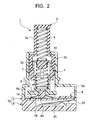
- FIG. 2 is a sectional view showing a non-actuated state of the push switch device
- FIG. 3 is a sectional view showing a pushed-state of the push switch device
- FIG. 4 is an exploded perspective view of the push switch device
- FIG. 5 is a plan view of a case provided with the switch device
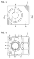
- FIG. 6 is a bottom view of the case
- FIG. 7 is a sectional view of the push switch device taken along the line VII - VII of FIG. 5
- FIG. 8 is a view of a guide portion formed to the case and explains the guide portion by developing it
- FIG. 9 is a front elevational view of an actuation body of the push switch device;
- FIG. 10 is a bottom view of the actuation body;
- FIG. 11 is a view of a first latchet tooth formed to the actuation body and explains the lathcet tooth by developing it;
- FIG. 12 is a plan view of a cam follower provided with the push switch device;
- FIG. 13 is a front elevational view of the cam follower;
- FIG. 14 is a bottom view of the cam follower;
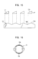
- FIG. 15 is a view of a second latchet tooth formed to the cam follower and explains the lathcet tooth by developing it;
- FIG. 16 is a plan view of a movable contact element provided with the push switch device;
- FIG. 16 is a plan view of a movable contact element provided with the push switch device;
- FIG. 17 is a plan view of a wafer provided with the push switch device;
- FIG. 18 is a front elevational view of the wafer;
- FIG. 19 is a side elevational view of the wafer;
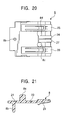
- FIG. 20 is a bottom view of the wafer;
- FIG. 21 is a sectional view of the wafer taken along the line XXI - XXI of FIG. 17;
- FIGS. 22A to 22G are views explaining the changes of phase of the first latchet tooth and the second latchet tooth;
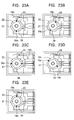
- FIGS. 23A to 23E are views explaining the contacting/departing states of the movable contact element to respective stationary contact elements;
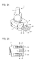
- FIG. 24 is a perspective view showing the state that three external terminals are connected to the push switch device;
- FIG. 24 is a perspective view showing the state that three external terminals are connected to the push switch device;
- FIG. 25 is a view explaining the connecting state of the three external terminals to connector terminal groups;
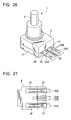
- FIG. 26 is a perspective view showing the state that four external terminals are connected to the push switch device;
- FIG. 27 is a view explaining the connecting state of the four external terminals to connector terminal groups;
- FIG. 28 is a sectional view showing the connecting state of an external terminal to a first connector terminal;
- FIG. 29 is a sectional view showing a connecting state of the external terminal to the second connector terminal;
- FIGS. 30A and 30B are plan views showing modifications of the wafer.
- the push switch device 1 includes a case 2 having a hollow internal structure, an actuation body 3 that can rises and falls in the up/down direction of the case 2, a cam follower 4 that can be moved in a rotational direction and the up/down direction by the rising/falling movement of the actuation body 3, a first coil spring 5 interposed between the actuation body 3 and the cam follower 4 and acting as an elastic member, an actuating member 6 that is spline coupled with the cam follower 4 and can be rotated integrally with it, a second coil spring 7 interposed between the cam follower 4 and the actuating member 6 and acting as a return spring, a wafer 8 rotatably supporting the actuating member 6, and a cover 9 for closing the lower opening end of the case 2, and a housing 10 is composed of the case 2 and the cover 9.
- the case 2 is molded of a synthetic resin material such as polybuthylene telephthalate (PBT) and the like and has a rectangular base 2a with its lower surface opened and a cylindrical portion 2b standing from the upper surface of the base 2a as shown in FIGS. 5 to 8.
- PBT polybuthylene telephthalate
- Four bosses 2c suspend downward from the inside of the base 2a, and a circular hole 2d is formed at the center on the upper surface of the cylindrical portion 2b.
- Four guide projections 11, which extend in an axial direction, are formed on the inner circumferential surface of the cylindrical portion 2b at equal intervals, and guide grooves 12 are formed between the respective guide projections 11.
- the guide projections 11 and the guide grooves 12 act as a guide portion for guiding the actuation body 3 in the up/down direction, and tapers 11a are formed the guide projections 11 at the lower end thereof.
- the actuation body 3 is molded of an elastomer composed of a block copolymer and the like of PBT and polyether. Used in this embodiment is a thermoplastic polyester elastomer, and, more specifically, a thermoplastic elastomer whose commodity name is "Hytrel" (trademark of Du Point) made by Du Point-Toray Co. Ltd. As shown in FIGS. 9 to 11, the actuation body 3 is formed to have the hollow structure with its lower end opened and has an actuating portion 3a projecting outwardly from the circular hole 2d of the case 2 and a large diameter portion 3b projecting radially outwardly from the lower portion of the actuating portion 3a.
- first latchet tooth 15 which extends along a circumferential direction, is formed at the lower end of the large diameter portion 3b and has four ridge portions 15a and four valley portions 15b that alternately continue in the circumferential direction. Note that the respective ridge portions 15a are located at the centers of the projections 13 in the circumferential direction thereof, and the respective valley portions 15b are located at the centers of the recesses 14 in the circumferential direction thereof.
- the cam follower 4 is molded of a synthetic resin material (plastomer) such as polyacetal (POM) excellent in slidability and arranged as a cylindrical body having a hollow structure with its lower end opened.
- the upper portion of the cam follower 4 is rotatably and upward and downward movably inserted into the large diameter portion 3b of the actuation body 3, and the first coil spring 5 is in elastic contact with the upper surface of the cam follower 4 and with the inner top surface of the actuation body 3 at both the ends thereof.
- plastomer synthetic resin material
- POM polyacetal
- a second latchet tooth 16 which extends along the circumferential direction, is formed on the outer circumferential surface of the cam follower 4 and has four ridge portions 16a and four valley portions 16b that alternately continue in the circumferential direction.
- the second latchet tooth 16 is engaged with the first latchet tooth 15 formed at the lower end of the actuation body 3.
- the first and second latchet teeth 15 and 16 are formed in approximately the same shape, only the extreme ends (apexes) of the ridge portions 16a of the second latchet tooth 16 are formed in an arc shape.
- four cam projections 17 are formed on the outer circumferential surface of the cam follower 4 at equal intervals, and tapers 17a are formed to the cam projections at the upper ends thereof.
- the respective cam projections 17 are somewhat offset in the circumferential direction with respect to the ridge portions 16a of the second latchet tooth 16.
- four engaging projections 18 are formed around the inner circumferential surface of the cam follower 4 at equal intervals and positioned at the centers in the circumferential direction with respect to the cam projections 17.
- the actuating member 6 is molded of the synthetic resin material (plastomer) such as polyacetal (POM) excellent in slidability and has a cylindrical portion 6a with its upper end opened and a disc portion 6b projecting radially outwardly from the lower end of the cylindrical portion 6a.
- plastomer synthetic resin material
- POM polyacetal
- the spring load of the second coil spring 7 interposed between the actuating member 6 and the cam follower 4 is set to a value that is sufficiently larger than that of the first coil spring 5 interposed between the cam follower 4 and the actuation body 3. That is, both the minimum and maximum loads of the second coil spring 7 are set sufficiently larger than those of the first coil spring 5. Accordingly, the second latchet tooth 16 is meshed with the first latchet tooth 15 by urging the cam follower 4 upward by imparting the spring force of the second coil spring 7 to the cam follower 4. Further, a movable contact element 19 is attached to the back surface of the disc portion 6b by means of thermal caulking and the like as well as a circular guide hole 6d is formed at the center of the actuating member 6. As shown in FIG. 16, the movable contact element 19 is formed in an approximately annular shape, and two sets of contact portions 19a and 19b are formed to the movable contact element 19 the diametrically opposite positions thereof.
- the wafer 8 is molded of the synthetic resin material such as PBT and the like. As shown in FIGS. 17 to 21, a columnar boss 8a stands on the upper surface of the wafer 8, and a columnar positioning pin 8b is suspend from the back surface thereof.
- the boss 8a acts as the fulcrum of rotation of the actuating member 6, and the guide hole 6d of the actuating member 6 is rotatably fitted on the boss 8a.
- a circular through-hole 8c and an oval through-hole 8d are formed through the wafer 8, the two bosses 2c of the four bosses 2c projecting from the base 2a of the case 2 extend to the back surface of the wafer 8 passing through these through-holes 8c and 8d, and the remaining two bosses 2c extend to the back surface of the wafer 8 passing through the cutouts at both the corners of the wafer 8.
- Four stationary contact elements 20, 21, 22, 23 are exposed on the upper surface of the wafer 8 and have connector terminals 24, 25, 26, 27 derived from the wafer 8.
- the stationary contact elements 20, 21, 22, 23 and the connector terminals 24, 25, 26, 27 are composed of an elastic metal sheet composed of Ag-plated phosphor bronze and the like and arranged integrally with the wafer 8 using an insert molding technology.
- the respective stationary contact elements 20, 21, 22, 23 are disposed concentrically about the boss 8a at predetermined intervals. As described later, when the actuating member 6 is rotated about the boss 8a, the contact portions 19a and 19b of the movable contact element 19 rotatingly slide on the stationary contact elements 20, 21, 22, 23.
- the four connector terminals 24, 25, 26, 27, which act as female type terminals to male type external terminals to be described later, are folded back from an end surface of the wafer 8 to the back surface thereof, and the width and the length of the two connector terminals 24 and 27, which are located adjacent to each other at a center, are set smaller than those of the remaining two connector terminals 25 and 26 located on both the sides of them.
- first and fourth connector terminals 24 and 27 located at the center are called first and fourth connector terminals 24 and 27, respectively
- the connector terminals 25 and 26 on the both sides are called second and fourth connector terminals 25 and 26, respectively
- first and fourth connector terminals 24 and 27 are formed in a cantilever state
- the second and third connector terminals 25 and 26 are formed in a clip shape.
- the cover 9 is formed of the synthetic resin material such as PBT and the like and formed in the same shape as the base 2a of the case 2 when viewed in a plane as shown in FIGS. 1 to 4.
- a plurality of transparent holes 9a are formed through the cover 9, and the respective bosses 2c of the case 2 and the positioning pin 8b of the wafer 8 are inserted into the transparent holes 9a and thermally caulked at the extreme ends thereof, thereby the wafer 8 is positioned and clamped between the case 2 and the cover 9 as well as the housing 10 is formed by integrating the case 2 and the cover 9 together.
- a recessed portion 28 is formed on the inner bottom surface of the cover 9, and the respective connector terminals 24, 25, 26, 27, which are folded back to the back surface of the wafer 8, are accommodated in the recessed portion 28 such that they can be deformed. Further, three insertion ports 29, 30, 31, which communicate with the recessed portion 28, are formed on a side of the cover 9.
- the first and fourth connector terminals 24 and 27 are disposed in the first insertion port 30 in proximity to each other, the second connector terminal 25 is disposed on a line extending from the second insertion port 29, and the third connector terminal 26 is disposed on a line extending from the third insertion port 31.
- tapers are formed to the peripheral edges (partition members) of the respective insertion ports 29, 30, 31 so that external terminals, which will be described later, can be smoothly inserted.
- the partition members for partitioning the plurality of insertion ports 29, 30, 31 may be formed integrally with the wafer 8 on the lower surface thereof.
- FIG. 2 shows a non-operating state in which no external force acts on the actuating portion 3a of the actuation body 3.
- the actuation body 3 and the cam follower 4 are urged to a rising position by the spring force of the second coil spring 7, and the respective projections 13 of the actuation body 3 and the cam projections 17 of the cam follower 4 are engaged with the guide grooves 12 of the case 2. Accordingly, the cam follower 4 can be moved only in the axial direction because the movement thereof in the rotational direction is regulated.
- the phase relationship between the ridge portions 16a of the second latchet tooth 16 and the ridge portions 15a of the first latchet tooth 15 is such that the ridge portions 16a are slightly offset from the ridge portions 15a as shown in FIG. 22A.
- the cam follower 4 is rotated by an angle (about 35°) slightly smaller than 45° that is one half the ridge of first and second latchet teeth 15 and 16 as well as the actuating member 6, which is spline coupled with the cam follower 4, is also rotated in association with the rotation of the cam follower 4.
- the actuating portion 3a of the actuation body 3 is further pushed, the actuation body 3 and the cam follower 4 fall integrally with each other while keeping the stable phase relation between the first and second latchet teeth 15 and 16 as shown in FIG. 22D and reach a stroke end position at which the actuating portion 3a of the actuation body 3 cannot be further pushed.
- the actuation body 3 and the cam follower 4 are caused to rise by the spring force of the second coil spring 7 as shown in FIG. 22E, thereby the cam projections 17 of the cam follower 4 are abutted against the lower ends of the guide projections 11.
- the tapers 11a are formed to the lower ends of the guide projections 11, and the tapers 17a, which have a taper angle different from that of the tapers 11a (that is, the tapers 17a have an acute angle with respect to an imaginary line parallel with the axial line of the actuation body 3), are also formed to the upper ends the cam projections 17.
- the cam projections 17 move along the lower ends of the guide projections 11 in approximately line contact therewith as shown in FIG. 22F and then enter the guide grooves 12 as shown in FIG. 22G to thereby rotate the cam follower 4. Therefore, the phase relationship between the first and second latchet teeth 15 and 16 shifts from the stable position to the unstable position. That is, after the ridge portions 16a of the second latchet tooth 16 move from the valley portions 15b of the first latchet tooth 15 to the valley portions 15b thereof as shown in FIG. 22F, the ridge portions 16a of the second latchet tooth 16 get over the ridge portions 15a of the first latchet tooth 15 as shown in FIG. 22G, thereby the phase relationship between the first and second latchet teeth 15 and 16 is set to the same phase relationship as that of the initial position shown in FIG. 22A.
- the cam follower 4 is rotated by one ridge of the first and second latchet teeth 15 and 16, and the actuating member 6 is also rotated by the same amount in association with the rotation of the cam follower 4.
- the first and second latchet teeth 15 and 16 have the four ridge portions 15a and 16a and the four valley portions 15b and 16b, respectively. Accordingly, when the actuation body 3 is pushed and released once, the cam follower 4 and the actuating member 6 are rotated 90°, and thereafter they are rotated each 90° in the same direction as the actuation body 3 is pushed and released repeatedly.
- the cam follower 4 is molded of the synthetic resin material (plastomer) excellent in slidability, when the cam projections 17 move along the lower ends (tapers 11a) of the guide projections 11 from the state shown in FIG. 22E, the cam projections 17 smoothly slide along the tapers 11a of the guide projections 11 without being caught by them, thereby the cam projections 17 can be securely entered into the guide grooves 12.
- the tapers 11a and 17a incline so as to be rotated by the spring force of the second coil spring 7 in the same direction as that they are rotated from the state shown in FIG. 22B to the state shown in FIG. 22C, so that the tapers 11a and 17a can shift to the state shown in FIG. 22G.
- the actuating member 6 is rotated by pushing and releasing the actuation body 3 as described above, which can change the contact states between contact portions 19a and 19b of the movable contact element 19 attached to the actuating member 6 and the respective stationary contact elements 20, 21, 22, 23 on the wafer 8.
- FIG. 23A it is assumed that the sate, in which the contact portion 19a of the movable contact element 19 comes into contact with the stationary contact element 20 at an upstream position thereof as well as the other contact portion 19b thereof comes into contact with the stationary contact element 22 at an upstream position thereof, is defined as the initial position corresponding to FIG. 22A.
- the first connector terminal 24 derived from the stationary contact element 20 is brought into electric conduction with the third connector terminal 26 derived from the stationary contact element 22 through the movable contact element 19, and the second and fourth connector terminal 25 and 27 derived from the remaining stationary contact element 21 and 23 are brought out of electric conduction therebetween.
- the actuating member 6 When the actuation body 3 is pushed to the stroke end position shown in FIG. 22(d), the actuating member 6 is rotated by an angle (about 35°) slightly smaller than one half the ridge of first and second latchet teeth 15 and 16 (45°). Accordingly, as shown in FIG. 23B, the contact portion 19a departs from the stationary contact element 20 and comes into contact with the stationary contact element 21 at an downstream position thereof as well as the other contact portion 19b departs from the stationary contact element 22 and comes into contact with the stationary contact element 23 at an downstream position thereof.
- the first and third connector terminals 24 and 26 derived from both the stationary contact elements 20 and 22 are brought out of electric conduction therebetween, and the second connector terminal 25 derived from the stationary contact element 21 is brought into electric conduction with the fourth connector terminal 27 derived from the stationary contact element 23 through the movable contact element 19.
- the actuating member 6 is rotated by an angle (about 55°) lightly larger than one half the ridge of first and second latchet teeth 15 and 16 (45°), that is, by one ridge (90°) based on the initial position. Accordingly, as shown in FIG. 23C, the contact portion 19a slidingly rotates from the downstream position of the stationary contact element 21 to the upstream position thereof as well as the other contact portion 19b slidingly rotates from the downstream position of the stationary contact element 23 to the upstream position thereof. Therefore, the non-electric-conduction state is maintained between the first and third connector terminals 24 and 26 as well as the electric conduction state is maintained between the second and fourth connector terminals 25 and 27.
- the actuating member 6 is rotated by an angle (about 35°) slightly smaller than the one half the ridge of first and second latchet teeth 15 and 16 (45°), that is, an angle (about 125°) slightly smaller than 3/2 ridge (135°) based on the initial position. Accordingly, the contact portion 19a departs from the stationary contact element 21 and comes into contact with the stationary contact element 22 at the downstream position thereof as well as the other contact portion 19b departs from the stationary contact element 23 and comes into contact with the stationary contact element 20 at a downstream position thereof. With the above operation, the first connector terminal 24 is brought into electric conduction with the third connector terminal 26 through the movable contact element 19 as well as the second and the fourth connector terminals 25 and 27 are brought out of electric conduction therebetween.
- the actuating member 6 is rotated by an angle (about 55°) lightly larger than one half the ridge of first and second latchet teeth 15 and 16 (45°), that is, by two ridges (180°) based on the initial position. Accordingly, as shown in FIG. 23E, the contact portion 19a slidingly rotates from the downstream position of the stationary contact element 20 to the upstream position thereof as well as the other contact portion 19b slidingly rotates from the downstream position of the stationary contact element 22 to the upstream position thereof. Therefore, the electric-conduction state is maintained between the first and third connector terminals 24 and 26 as well as the non-electric-conduction state is maintained between the second and fourth connector terminals 25 and 27.
- the respective stationary contact elements 20, 21, 22, 23 are formed in the arc shape and explained above by defining for convenience that the portions thereof located in a clockwise direction are the upward positions and the portions thereof located in a counterclockwise direction are the downstream positions.
- the contact portions 19a and 19b of the movable contact element 19 come into contact with and depart from the respective stationary contact elements 20, 21, 22, 23 by repeatedly pushing the releasing the actuation body 3.
- the stationary contact elements 20 and 23, which are in electric conduction with the first and fourth connector terminals 24 and 27, are examined, any one of the contact portions 19a and 19b of the movable contact element 19 is in a contact state at all times, thereby three external terminals and four external terminals can be selectively connected to the push switch device 1.
- the stationary contact elements 20 and 23 acts as a single common stationary contact element, so that the push switch device 1 can be used as a push switch device having a one-circuit/two-contact elements structure.
- both the external terminals 33A are inserted into the second and third insertion ports 29 and 31, respectively as well as the two external terminals 33B are inserted into the first insertion port 30, the four external terminals 33 are in electric conduction with the first to fourth connector terminals 24, 25, 26, 27 which correspond thereto, independently.
- all the stationary contact elements 20, 21, 22, and 23 act as switching stationary contact elements, thereby the push switch device 1 can be used as a push switch device having a two-circuits/two-contact elements structure.
- the first coil spring 5 which has the spring load smaller than that of the second coil spring 7, is interposed between the actuation body 3 and the cam follower 4, when the phase of the ridge portions 16a of the second latchet tooth 16 is shifted to the stable position by pushing the actuation body 3, that is, when the phase relationship between the first and second latchet teeth 15 and 16 is shifted from the position shown in FIG. 22B to the position shown by FIG. 22C, the first coil spring 5 acts in a direction where the spring force of the second coil spring 7 is reduced, thereby the noise generated when the ridge portions 16a of the second latchet tooth 16 are abutted against the valley portions 15b of the first latchet tooth 15 is reduced.
- the phase of the ridge portions 16a of the second latchet tooth 16 is shifted from the stable position to the unstable position by releasing the actuation body 3, that is, when the phase relationship between the first and second latchet teeth 15 and 16 is shifted from the position shown in FIG. 22E to the position shown in FIG. 22G, since the first coil spring 5 also acts in the direction where the spring force of the second coil spring 7 is reduced, the ridge portions 16a of the second latchet tooth 16 smoothly move from the valley portions 15b of the first latchet tooth 15 to the ridge portions 15a thereof, thereby the kick noise generated when the ridge portions 16a get over the ridge portions 15a is reduced. Therefore, the abutment noise of the first and second latchet teeth 15 and 16 can be reduced while securing the initial push force necessary to the actuation body 3.
- the first latchet tooth 15 is formed to the actuation body 3 composed of the elastomer and the second latchet tooth 16 is formed to the cam follower 4 composed of the synthetic resin (plastomer), the abutment noise can be more effectively reduced when the phase of the ridge portions 16a of the second latchet tooth 16 is shifted to the stable position as the actuation body 3 is pressed and when the phase of the ridge portions 16a of the second latchet tooth 16 is shifted from the stable position to the unstable position as the actuation body 3 is released. Further, since the second latchet tooth 16 is composed of the material excellent in slidability, the wear of the first latchet tooth 15 composed of the elastomer can be reduced.
- the extreme ends (apexes) of the ridge portions 16a of the second latchet tooth 16 are rounded in the arc shape, when the phase of the ridge portions 16a of the second latchet tooth 16 is shifted from the stable position to the unstable position as the actuation body 3 is released, the ridge portions 16a of the second latchet tooth 16 can smoothly get over the ridge portions 15a of the first latchet tooth 15, by which the abutment noise of the first and second latchet teeth 15 and 16 can be also reduced.
- the wafer 8 accommodated in the housing 10 is provided with the four stationary contact elements 20, 21, 22, 23 and the connector terminals 24, 25, 26, 27 derived from the respective stationary contact elements 20, 21, 22, 23, and the two connector terminals 24 and 27 of these connector terminals 24, 25, 26, 27, which are connected to the stationary contact elements 20 and 23 that are alternately brought into electric conduction with the movable contact element 19 as the actuation body 3 is actuated, are disposed in the common insertion port 30 adjacent to each other as well as the remaining two connector terminals 25 and 26 are independently disposed in the two insertion ports 29 and 31.
- the external terminal 32 inserted through the common insertion port 30 can be simultaneously brought into electric conduction with the two connector terminals 24 and 27, and the two external terminals 33B inserted through the common insertion port 30 can be independently brought into electric conduction with the two connector terminals 24 and 27. That is, since the two stationary contact elements 20 and 23 of the our stationary contact elements 20, 21, 22, 23 act as the common stationary contact element or the individual switching stationary contact elements, it is possible to selectively derive ON/OFF signals from the respective stationary contact elements 20, 21, 22, 23 so that they can be used for one circuit and two circuits, which permits the versatility in use of the push switch device 1 to be increased.
- the embodiment may be provided with, for example, a power conversion mechanism for converting the rotating motion of the actuating member into a linear motion, and the actuating member may actuate the contact element switching mechanism through the power conversion mechanism.
- the push switch device which can be selectively used as the one-circuit/two contact elements push switch device and the two-circuits/two contact elements push switch device by disposing the four stationary contact elements 20, 21, 22, 23 to the wafer 8 and causing the two stationary contact elements 20 and 23 to act as the one common stationary contact element or the individually switching stationary contact elements. It is a matter of course, however, that the push switch device can be applied to a push switch device dedicated for one-circuit/two contact elements. In this case, as shown in FIGS. 30A and 30B, two stationary contact elements 34 and 35 and one common stationary contact element 36 are exposed on the upper surface of the wafer 8 as well as three connector terminals 37, 38, 39 connected to the respective stationary contact elements 34, 35, 36 are derived from the wafer 8.
Landscapes
- Push-Button Switches (AREA)
- Mechanisms For Operating Contacts (AREA)
Abstract
Description
Claims (6)
- A push switch device comprising:wherein at least one of the actuation body and the cam follower is formed of an elastomer.a housing arranged in a hollow structure and having a guide portion formed on an inner surface;an actuation body which can be moved in an axial direction by being guided by the guide portion and to which a first latchet tooth is formed so as to extend in a circumferential direction;a cam follower which is disposed in the housing so as to rotate as well as to move in an axial direction and to which a second latchet tooth is formed so as to be engaged with the first latchet tooth;a return spring for elastically urging the cam follower in the axial direction so that the first latchet tooth is engaged with the second latchet tooth;a rotatable actuating member spline coupled with the cam follower; anda contact element switching mechanism actuated by the rotation of the actuating member,
- A push switch device according to claim 1, wherein the actuation body is formed of the elastomer as well as the cam follower is formed of a plastomer whose elasticity is lower than that of the elastomer.
- A push switch device comprising:wherein at least the extreme ends of the tooth portions of one of the first and second latchet teeth are formed in an arc shape.a housing arranged in a hollow structure and having a guide portion formed on an inner surface;an actuation body which can be moved in an axial direction by being guided by the guide portion and to which a first latchet tooth is formed so as to extend in a circumferential direction;a cam follower which is disposed in the housing so as to rotate as well as to move in an axial direction and to which a second latchet tooth is formed so as to be engaged with the first latchet tooth;a return spring for elastically urging the cam follower in the axial direction so that the first latchet tooth is engaged with the second latchet tooth;a rotatable actuating member spline coupled with the cam follower; anda contact element switching mechanism actuated by the rotation of the actuating member,
- A push switch device comprising:wherein an elastic member whose spring load is smaller than that of the return spring is interposed between the actuation body and the cam follower.a housing arranged in a hollow structure and having a guide portion formed on an inner surface;an actuation body which can be moved in an axial direction by being guided by the guide portion and to which a first latchet tooth is formed so as to extend in a circumferential direction;a cam follower which is disposed in the housing so as to rotate as well as to move in an axial direction and to which a second latchet tooth is formed so as to be engaged with the first latchet tooth;a return spring for elastically urging the cam follower in the axial direction so that the first latchet tooth is engaged with the second latchet tooth;a rotatable actuating member spline coupled with the cam follower; anda contact element switching mechanism actuated by the rotation of the actuating member,
- A push switch device according to claim 4, wherein both the return spring and the elastic member comprise a coil spring.
- A push switch device according to claim 4 or 5,
wherein at least one of the actuation body and the cam follower is formed of the elastomer.
Applications Claiming Priority (4)
| Application Number | Priority Date | Filing Date | Title |
|---|---|---|---|
| JP2003022333 | 2003-01-30 | ||
| JP2003022333 | 2003-01-30 | ||
| JP2003409271 | 2003-12-08 | ||
| JP2003409271A JP4323301B2 (en) | 2003-01-30 | 2003-12-08 | Push switch device |
Publications (2)
| Publication Number | Publication Date |
|---|---|
| EP1443535A2 true EP1443535A2 (en) | 2004-08-04 |
| EP1443535A3 EP1443535A3 (en) | 2006-04-05 |
Family
ID=32658604
Family Applications (1)
| Application Number | Title | Priority Date | Filing Date |
|---|---|---|---|
| EP04001680A Withdrawn EP1443535A3 (en) | 2003-01-30 | 2004-01-27 | Push switch device |
Country Status (5)
| Country | Link |
|---|---|
| US (1) | US7030331B2 (en) |
| EP (1) | EP1443535A3 (en) |
| JP (1) | JP4323301B2 (en) |
| CN (2) | CN100511529C (en) |
| TW (1) | TWI233134B (en) |
Cited By (5)
| Publication number | Priority date | Publication date | Assignee | Title |
|---|---|---|---|---|
| CN101377982B (en) * | 2007-08-31 | 2011-02-09 | 阿尔卑斯电气株式会社 | Button switch device |
| CN102723219A (en) * | 2012-06-20 | 2012-10-10 | 科都电气有限公司 | Kick switch with locking mechanism |
| CN103730281A (en) * | 2013-11-25 | 2014-04-16 | 上海航空电器有限公司 | Elastic connecting mechanism of square through connection circular button |
| EP2835809A1 (en) * | 2013-08-09 | 2015-02-11 | Omron Corporation | Switch and keyboard provided therewith |
| EP2757567B1 (en) * | 2013-01-18 | 2016-12-28 | Omron Corporation | Push button switch |
Families Citing this family (31)
| Publication number | Priority date | Publication date | Assignee | Title |
|---|---|---|---|---|
| WO2008066072A1 (en) * | 2006-11-30 | 2008-06-05 | Alps Electric Co., Ltd. | Push switch device |
| JP5017180B2 (en) * | 2008-05-30 | 2012-09-05 | アルプス電気株式会社 | Push switch device |
| CA2742874C (en) * | 2008-11-06 | 2018-03-27 | Mec A/S | An electrical switch |
| KR100927253B1 (en) * | 2009-02-05 | 2009-11-16 | (주)카마다코리아 | Rotary push switch |
| KR101076498B1 (en) | 2010-06-30 | 2011-10-24 | 한국오므론전장주식회사 | Switch structure |
| CN102280290A (en) * | 2011-06-16 | 2011-12-14 | 苏州市诺弗电器有限公司 | Reset button apparatus of switch |
| CN103681047B (en) * | 2012-09-10 | 2015-11-25 | 光宝电子(广州)有限公司 | Button and acoustics |
| JP5236832B1 (en) * | 2012-10-17 | 2013-07-17 | 株式会社東海理化電機製作所 | Operating device |
| CN103779122A (en) * | 2012-10-26 | 2014-05-07 | 崧腾企业股份有限公司 | Hot spot far-away type press switch structure |
| JP5968232B2 (en) * | 2013-01-08 | 2016-08-10 | ホシデン株式会社 | Push switch |
| USD720704S1 (en) * | 2013-05-16 | 2015-01-06 | Hosiden Corporation | Push switch |
| CN103943398B (en) * | 2014-04-04 | 2017-05-17 | 余正明 | Long-stroke microswitch |
| CN103928255B (en) * | 2014-04-04 | 2017-11-10 | 余正明 | A kind of long stroke waterproof micro switch |
| JP6413936B2 (en) * | 2015-06-05 | 2018-10-31 | 豊田合成株式会社 | Lid device with lock mechanism |
| JP6499600B2 (en) * | 2016-02-23 | 2019-04-10 | ミヤマ電器株式会社 | Push switch |
| JP2019071166A (en) * | 2016-03-01 | 2019-05-09 | パナソニックIpマネジメント株式会社 | Push switch |
| KR101789265B1 (en) | 2016-05-20 | 2017-10-25 | 유철상 | A push switch for a car room lamp |
| DE102016117021A1 (en) | 2016-09-09 | 2018-03-15 | Nbb Holding Ag | control unit |
| DE102016117022A1 (en) | 2016-09-09 | 2018-03-15 | Nbb Holding Ag | Input device for inputting a control command and operating device with such an input device |
| KR101835826B1 (en) | 2016-12-05 | 2018-03-07 | 유철상 | A push switch for a car room lamp |
| WO2018139077A1 (en) * | 2017-01-24 | 2018-08-02 | アルプス電気株式会社 | Push switch |
| CN108105730B (en) * | 2017-12-16 | 2020-09-04 | 新沂市时集建设发展有限公司 | ballast for lamp |
| CN108131649B (en) * | 2017-12-16 | 2020-09-08 | 新沂市时集建设发展有限公司 | Lamp ballast with improved connection structure |
| US11081299B2 (en) * | 2018-05-09 | 2021-08-03 | Illinois Tool Works Inc. | Snap action switch for generating feedbacks |
| CN109626284B (en) * | 2019-01-24 | 2021-02-26 | 合肥工业大学 | A hooking device suitable for intelligent lifting equipment |
| JP7236291B2 (en) * | 2019-03-07 | 2023-03-09 | 東洋電装株式会社 | switch device |
| JP7271287B2 (en) * | 2019-04-19 | 2023-05-11 | Idec株式会社 | switch device |
| EP4314982A4 (en) * | 2021-03-22 | 2025-01-01 | Penn Engineering & Manufacturing Corp. | Push button |
| JP7694188B2 (en) * | 2021-06-22 | 2025-06-18 | オムロン株式会社 | Switch device and key input device |
| CN114038708B (en) * | 2021-11-15 | 2024-04-12 | 浙江法拉迪电力科技有限公司 | Single-phase circuit breaker transmission mechanism and operating mechanism with same |
| CN119446822A (en) * | 2023-08-01 | 2025-02-14 | 阿尔卑斯阿尔派株式会社 | Push switch device |
Family Cites Families (13)
| Publication number | Priority date | Publication date | Assignee | Title |
|---|---|---|---|---|
| US3718786A (en) * | 1971-08-05 | 1973-02-27 | Tri Line Electric Co Inc | Rotary switch assembly |
| US4319106A (en) * | 1980-03-31 | 1982-03-09 | Armitage Ralph T | Push button switch |
| US4506124A (en) * | 1983-10-19 | 1985-03-19 | Amp Incorporated | Push-push switch |
| US4891476A (en) * | 1988-05-09 | 1990-01-02 | Illinois Tool Works, Inc. | Index rotary switch |
| US5132499A (en) * | 1989-05-16 | 1992-07-21 | Judco Manufacturing, Inc. | Pre-loaded switching apparatus and method of operation |
| US5049709A (en) * | 1990-01-30 | 1991-09-17 | Illinois Tool Works, Inc. | Index rotary switch with rotor contact member having L-shaped arms |
| US5087803A (en) * | 1990-05-22 | 1992-02-11 | Hubbell Incorporated | Electrical switch for hazardous environments |
| US5186316A (en) * | 1990-09-14 | 1993-02-16 | Lee Craft Manufacturing Co., Inc. | Stable-on push-push electrical switch |
| US5178265A (en) * | 1991-02-04 | 1993-01-12 | White Consolidated Industries, Inc. | Push-push snap switch |
| US6160225A (en) * | 1997-07-03 | 2000-12-12 | Alp Electric Co., Ltd. | Multidirectional inputting apparatus |
| US5967301A (en) * | 1998-02-27 | 1999-10-19 | Delco Electronics Corporation | Popout control assembly for radios |
| CN2362187Y (en) * | 1998-06-08 | 2000-02-02 | 翁经通 | multi-stage switch |
| JP4132889B2 (en) * | 2002-03-14 | 2008-08-13 | ミヤマ電器株式会社 | Push switch |
-
2003
- 2003-12-08 JP JP2003409271A patent/JP4323301B2/en not_active Expired - Fee Related
-
2004
- 2004-01-20 US US10/761,780 patent/US7030331B2/en not_active Expired - Lifetime
- 2004-01-27 EP EP04001680A patent/EP1443535A3/en not_active Withdrawn
- 2004-01-28 TW TW093101859A patent/TWI233134B/en not_active IP Right Cessation
- 2004-01-30 CN CNB2004100035628A patent/CN100511529C/en not_active Expired - Lifetime
- 2004-01-30 CN CN200910146614XA patent/CN101572198B/en not_active Expired - Lifetime
Cited By (7)
| Publication number | Priority date | Publication date | Assignee | Title |
|---|---|---|---|---|
| CN101377982B (en) * | 2007-08-31 | 2011-02-09 | 阿尔卑斯电气株式会社 | Button switch device |
| CN102723219A (en) * | 2012-06-20 | 2012-10-10 | 科都电气有限公司 | Kick switch with locking mechanism |
| CN102723219B (en) * | 2012-06-20 | 2014-09-24 | 科都电气有限公司 | Kick switch with locking mechanism |
| EP2757567B1 (en) * | 2013-01-18 | 2016-12-28 | Omron Corporation | Push button switch |
| EP2835809A1 (en) * | 2013-08-09 | 2015-02-11 | Omron Corporation | Switch and keyboard provided therewith |
| CN103730281A (en) * | 2013-11-25 | 2014-04-16 | 上海航空电器有限公司 | Elastic connecting mechanism of square through connection circular button |
| CN103730281B (en) * | 2013-11-25 | 2018-01-16 | 上海航空电器有限公司 | A kind of flexible connection mechanism of square switching round button |
Also Published As
| Publication number | Publication date |
|---|---|
| CN101572198A (en) | 2009-11-04 |
| EP1443535A3 (en) | 2006-04-05 |
| CN1521787A (en) | 2004-08-18 |
| JP2004253368A (en) | 2004-09-09 |
| US20040149560A1 (en) | 2004-08-05 |
| US7030331B2 (en) | 2006-04-18 |
| JP4323301B2 (en) | 2009-09-02 |
| TWI233134B (en) | 2005-05-21 |
| CN101572198B (en) | 2011-09-07 |
| TW200428439A (en) | 2004-12-16 |
| CN100511529C (en) | 2009-07-08 |
Similar Documents
| Publication | Publication Date | Title |
|---|---|---|
| US7030331B2 (en) | Push switch device | |
| US6262380B1 (en) | Single manipulation unit switching device | |
| KR20150135187A (en) | Push-button switch | |
| JP5968232B2 (en) | Push switch | |
| JP4088166B2 (en) | Switch device | |
| JP2004281259A (en) | Push switch device | |
| JP3764799B2 (en) | Rotating electrical parts | |
| JP3404441B2 (en) | Composite operation type electric parts | |
| JP3404442B2 (en) | Composite operation type electric parts | |
| JP2004178989A (en) | Rotary switch | |
| JP2008152966A (en) | Rotating body return mechanism | |
| JP3767996B2 (en) | Push switch device | |
| JPH0338917Y2 (en) | ||
| JP3139580B2 (en) | Push button switch | |
| JPH0648716Y2 (en) | Small switch | |
| KR0119496Y1 (en) | Switching device for zooming of camcorder | |
| EP0626706A1 (en) | Electrical switch | |
| JP3416400B2 (en) | Composite operation type electric parts | |
| JP6643150B2 (en) | Rotary electronic components | |
| JPH08279317A (en) | Rotary electronic components with click function | |
| JP2014093290A (en) | Contact member | |
| JPH051126U (en) | Push button switch | |
| JPH0727540Y2 (en) | Push button switch | |
| JP2522020Y2 (en) | Push switch | |
| JPS633602Y2 (en) |
Legal Events
| Date | Code | Title | Description |
|---|---|---|---|
| PUAI | Public reference made under article 153(3) epc to a published international application that has entered the european phase |
Free format text: ORIGINAL CODE: 0009012 |
|
| AK | Designated contracting states |
Kind code of ref document: A2 Designated state(s): AT BE BG CH CY CZ DE DK EE ES FI FR GB GR HU IE IT LI LU MC NL PT RO SE SI SK TR |
|
| AX | Request for extension of the european patent |
Extension state: AL LT LV MK |
|
| PUAL | Search report despatched |
Free format text: ORIGINAL CODE: 0009013 |
|
| AK | Designated contracting states |
Kind code of ref document: A3 Designated state(s): AT BE BG CH CY CZ DE DK EE ES FI FR GB GR HU IE IT LI LU MC NL PT RO SE SI SK TR |
|
| AX | Request for extension of the european patent |
Extension state: AL LT LV MK |
|
| 17P | Request for examination filed |
Effective date: 20060502 |
|
| AKX | Designation fees paid |
Designated state(s): DE FR GB IT |
|
| STAA | Information on the status of an ep patent application or granted ep patent |
Free format text: STATUS: THE APPLICATION HAS BEEN WITHDRAWN |
|
| 18W | Application withdrawn |
Effective date: 20091022 |