EP1443462A2 - Image editing device, method for trimming image, and program therefor - Google Patents
Image editing device, method for trimming image, and program therefor Download PDFInfo
- Publication number
- EP1443462A2 EP1443462A2 EP04001195A EP04001195A EP1443462A2 EP 1443462 A2 EP1443462 A2 EP 1443462A2 EP 04001195 A EP04001195 A EP 04001195A EP 04001195 A EP04001195 A EP 04001195A EP 1443462 A2 EP1443462 A2 EP 1443462A2
- Authority
- EP
- European Patent Office
- Prior art keywords
- trimming
- image
- template
- noticing
- area
- Prior art date
- Legal status (The legal status is an assumption and is not a legal conclusion. Google has not performed a legal analysis and makes no representation as to the accuracy of the status listed.)
- Withdrawn
Links
Images


Classifications
-
- G—PHYSICS
- G06—COMPUTING OR CALCULATING; COUNTING
- G06T—IMAGE DATA PROCESSING OR GENERATION, IN GENERAL
- G06T11/00—Two-dimensional [2D] image generation
- G06T11/60—Creating or editing images; Combining images with text
Definitions
- the present invention relates to an image editing device, a method for editing the image, and a computer program therefor so as to trim (cut a part of the image or clip out a part of the image) a digital image (hereinafter, "image” means the digital image) which is taken by a digital camera automatically.
- the invention which is disclosed in Japanese Unexamined Patent Application, First Publication No. 2002-10056 relates to an image synthesizing device for producing a synthesized image easily in which a main image is overlapped on a background image.
- an outer frame and an inner frame which is disposed inside the outer frame are displayed in a sub-display area. Consequently, the picked up background image is displayed in a main display area.
- a trimming frame is displayed so as to correspond to the outer frame in the sub-display area.
- a range for moving the trimming frame which is supposed to be synthesized is designated.
- the background image is clipped on the outer frame in the sub-display area.
- main image is picked up so as to be displayed in the main display area.
- a trimming frame is displayed in the main display area so as to correspond to the inner frame of the sub-display area.
- a portion which is designated in the trimming frame is fitted in the inner frame of the sub-display area.
- An object of the present invention is to provide an image editing device, a method for trim the image, and a computer program therefor which can trim the noticing area in the image automatically such that it is possible to trim the image easily and efficiently.
- An image editing device for trimming an image comprises a noticing area calculating section for calculating a noticing area of an image which is an object for a trimming operation, a trimming rule designating section for designating a trimming method for trimming the noticing area of the image which is the object for the trimming operation, a trimming shape designating section for designating a shape of a trimming scope when the designating operation of the trimming scope is selected by the trimming rule designating section, a template selecting section for selecting a template which is used for the trimming operation among a template group which is memorized in advance when a using operation for the template is designated by the trimming rule designating section, a noticing area error calculating section for calculating distribution ratio of the noticing area in the trimming scope or the template, and an image processing section for enlarging, contracting, and rotating the image, the trimming scope, and the template so as to adjust the distribution ratio of the noticing area in the trimming scope or the template according to the method which is designated by the trimming rule
- the noticing area calculating section determines the noticing area in the image which is supposed to be trimmed.
- a method for trimming the noticing area is designated by the trimming rule designating section.
- a scope (shape) which is supposed to be trimmed by the user is designated by the trimming shape designating section when a designating operation for the trimming scope is selected by the trimming rule designating section.
- the user selects the template which is used for the trimming operation among the template group which is memorized in advance by the template selecting section. Also, a distribution ratio of the noticing area in the trimming scope or the template is calculated by the noticing area error calculating section.
- an enlarging operation or a contracting operation for the image, the trimming scope, or the template are performed so as to adjust the distribution ratio of the noticing area in the trimming scope or the template according to a method which is designated by the trimming rule designating section by using the image processing section.
- the trimming scope shape
- the template shape
- the noticing area is calculated according to human visual characteristics; thus, it is possible to trim the image automatically. Also, the noticing area is trimmed visually desirably according to the designated trimming scope or the template.
- the image editing device further comprises a center aligning section for aligning a center of the noticing area and a center of the trimming scope or a center of the template.
- the extent that the noticing area is cut (the distribution ratio of the noticing area in the trimming scope or the template) is calculated by the noticing area error calculating section.
- the center of the noticing area is a crossing point of diagonal lines of a rectangle which surrounds the noticing area
- the center of the template is a crossing point of diagonal lines of a rectangle which surrounds the template.
- the noticing area is surrounded by a rectangle.
- the cross point of the diagonal lines of the rectangle is disposed so as to be a center in the noticing area.
- the trimming scope or the template is surrounded by the rectangle such that the cross point of the diagonal lines is disposed so as to be a center of the trimming scope or the center of the template.
- the image editing device further comprises a noticing area threshold section which determines a threshold with reference to the noticing area having the highest attention and determines the noticing area having the attention which is higher than the threshold when the noticing area is calculated by the noticing area calculating section.
- thresholds so as to cut (clip out) the noticing areas so as to organize the noticing areas in an area such that the threshold may indicate an area which has the highest attractiveness in the calculated noticing areas, or an area which has more than a half of the highest attractiveness in the noticing area threshold section.
- a method for trimming an image in an image editing device comprises the steps of calculating a noticing area of an image which is an object for a trimming operation, designating a trimming method for trimming the noticing area of the image which is the object for the trimming operation, designating a shape of a trimming scope when the designating operation of the trimming scope is selected by the trimming rule designating section, selecting a template which is used for the trimming operation among a template group which is memorized in advance when a using operation for the template is designated by the trimming rule designating section, calculating distribution ratio of the noticing area in the trimming scope or the template, and enlarging, contracting, and rotating the image, the trimming scope, and the template so as to adjust the distribution ratio of the noticing area in the trimming scope or the template according to the method which is designated by the trimming rule designating section.
- the noticing area which is supposed to be trimmed is determined in the noticing area calculating step.
- a method for trimming the noticing area is designated in the trimming rule designating step.
- the trimming scope (shape) which is supposed to be trimmed by the user is designated in the trimming shape designating step.
- the template which is supposed to be used for the trimming operation by the user is selected among the template group which is memorized in advance in the template selecting step.
- the distribution ratio of the noticing area in the trimming scope or the template is calculated in the noticing area error calculating step.
- an enlarging operation or a contracting operation for the image, the trimming scope, or the template are performed so as to adjust the distribution ratio of the noticing area in the trimming scope or the template according to a method which is designated in the trimming rule designating step by using the image processing step.
- the noticing area is calculated according to human visual characteristics; thus, it is possible to trim the image automatically. Also, the noticing area is trimmed visually desirably according to the designated trimming scope or the template.
- a computer program comprises the steps of calculating a noticing area of an image which is an object for a trimming operation, designating a trimming method for trimming the noticing area of the image which is the object for the trimming operation, designating a shape of a trimming scope when the designating operation of the trimming scope is selected by the trimming rule designating section, selecting a template which is used for the trimming operation among a template group which is memorized in advance when a using operation for the template is designated by the trimming rule designating section, calculating distribution ratio of the noticing area in the trimming scope or the template, and enlarging, contracting, and rotating the image, the trimming scope, and the template so as to adjust the distribution ratio of the noticing area in the trimming scope or the template according to the method which is designated by the trimming rule designating section.
- FIG 1 is a block diagram for explaining a structure for devices which are provided with the image editing device 100 according to the present invention.
- each section performs following operation.
- An image selecting section 101 selects an image which is supposed to be an object for the trimming operation in an image memorizing section 114.
- An image reading-out section 102 reads out values such as RGB values or the likes per pixel which forms the image.
- a noticing area calculating section 103 calculates the noticing area in an image which is supposed to be an object in the trimming operation so as to separate the image into a plurality of areas and categorize the separated image areas according to more than two noticing degrees.
- the "attractiveness" can be used which is disclosed for an ''NOTICING AREA EXTRACTING DEVICE AND AUTOMATIC COMPOSITION DECIDING DEVICE” in Japanese Unexamined Patent Application, First Publication No. 2001-126070.
- the attractiveness is explained generally in a later paragraph which is titled "Supplemental Explanation for the Attractiveness".
- FIG. 2 is a view for showing image 11 which is an object for the trimming operation graphically.
- FIG. 3 is a view for explaining an noticing degree (attractiveness) of the image 11 shown in FIG. 2 graphically so as to show a pattern image 12 in the noticing area.
- an area A has the highest the noticing degree (attractiveness) according to the calculation such that area B have the second highest noticing degree (attractiveness) and the area C have the third highest noticing degree (attractiveness).
- the noticing area threshold section 104 determines thresholds so as to cut (clip out) the noticing areas so as to organize the noticing areas such that the threshold may indicate an area which has the highest noticing degree (attractiveness) in the calculated noticing areas, or an area which has more than a half of the highest noticing degree (attractiveness) in the noticing area threshold section among the noticing area which is determined by the noticing area calculating section 103.
- the trimming operation is determined in a case in which the trimming scope is determined, such noticing areas to which thresholds are arranged are used.
- FIG 4 is a view for an example for an image 13 which is formed by cutting the noticing area in the pattern image 12 in the noticing area shown in FIG. 3 according to the threshold (attractiveness in the area B) by using the noticing area threshold section 104. That is, in the pattern image 12 in the noticing area shown in FIG. 13, a portion having a higher noticing (attractiveness) in the area B than the threshold is clipped out. The area B and the area A are clipped. Consequently, the clipped-out areas A and B are organized unitarily; thus, it is possible to form a noticing area 13a which is supposed to be an object for the trimming operation shown in FIG 4. Furthermore, the center of the noticing area 13a to which the threshold is arranged is disposed so as to be a center of the rectangular area 14 which surrounds the noticing area 13a.
- the trimming rule designating section 105 is used by a user for designating a trimming method.
- the user selects the trimming rule, for example, among following methods.
- a magnification of the noticing area in a range of, for example, 98 % to 102 %.
- the range such as ⁇ 5 pixels vertically or horizontally.
- the trimming shape designating section 106 is used for the user to designate the trimming range in any desirable shape.
- FIGS. 5A and 5B are views for examples of designating operation for the trimming scope such that the user can designate a shape 21 of the trimming scope which is shown in FIG 5A and a shape 22 of the trimming scope which is shown in FIG 5B by dragging a computer mouse on a computer display by using the trimming shape designating section 106.
- the template selecting section 107 selects the template for describing the trimming shape of the image.
- FIGS. 6 to 8 are views for showing examples for the templates which are used for the trimming operation such that the user can select the template for the trimming operation among the templates 31, 32 or 33.
- the noticing area error calculating section 108 is used for calculating a degree of the noticing area (degree of distribution in the template, or the like) to which the threshold is arranged which is cut according to the trimming scope or the template. In such a case, the noticing area is determined by the noticing area threshold section 104. Also, the template is memorized in the template memorizing section 115 so as to be selected by the user.
- An error in the noticing area is calculated by using the template 31 (shown in FIG 6) as follows.
- a method for determining the center of the template 31 is similar to a method shown in FIG 4 for example. That is, the template is surrounded by a rectangle such that a center of the diagonal lines in the rectangle is disposed so as to be the center of the template.
- the image processing section 109 is formed by an image scaling section 110 and an image rotating section 111 so as to perform following functions.
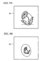
- FIGS. 9A and 9B show examples in which the image is distributed in the template.
- FIG 9A an example is shown in which the image shown in FIG 2 is distributed in the template 31 which is shown in FIG. 6.
- the noticing area (a portion of image which shows a flower) in the image 34 of the image is too large; therefore, a portion having a higher noticing degree (attractiveness) expands over the template.
- a contracting ratio of the noticing area 13a (shown in FIG. 4) to which the threshold is arranged is determined by the image processing section 109 and the noticing area error calculating section 108. After that the image of the flower is distributed in the template 31.
- the noticing area As shown in a case for the image 35 which is shown in FIG. 9B, it is possible to trim entire noticing area so as to be included in the template 31.
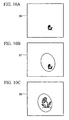
- FIGS. 10A to 10C are views for showing other examples than the examples in the FIGS. 9A and 9B in which images are distributed in the templates.
- FIG 10B an example is shown in which the image 37 is formed by distributing the image 36 which is shown in FIG 10A in the template 31 which is shown in FIG 6.
- the noticing area (a portion of the image of the flower) of the image 10(b) of the image is too small.
- a magnification of the image of the flower is determined by the image processing section 109 and the noticing area error calculating section 108 so as to be distributed in the template 21.
- the noticing area By enlarging the noticing area in this way, it is possible to trim the noticing area such as an image 38 shown in FIG. 10C visually desirably.
- the displaying section 112 displays the trimming result.
- the printing section 113 prints the trimming result.
- the image memorizing section 114 memorizes an image data which is supposed to be an object for the trimming operation and the trimmed image data.
- the template memorizing section 115 memorizes the template on which a trimming method is written. Examples for the template area shown in FIGS. 6 to 8.
- the image editing device By using the sections which are explained above, in the image editing device according to the present invention, it is possible to trim the image easily by calculating the noticing area according to the human visual characteristics, designating the trimming scope (shape), and selecting the template.
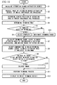
- FIG. 11 is a flow chart for showing processing steps in the image editing device according to the present invention so as to select the template and trim the image.
- the trimming rule is established under following conditions by the trimming rule designating section 105.
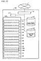
- FIG 12 is a block diagram for showing an example for the image editing device according to the present invention in which only the sections which relate to the present invention are shown.
- reference numeral 100 indicates an image editing device.
- Reference numeral 1 indicates a communication network such as Internet.
- Reference numeral 116 indicates a communication interface for connecting the image editing device 100 and the communication network 1.
- Reference numeral 117 indicates a controlling section which controls an entire image editing device integrally.
- Reference numeral 120 indicates a processing program section.
- the image editing device according to the present invention can be realized by using a PC (personal computer).
- processing program section 120 is provided with following processing sections.
- the image data for the trimming operation and the trimmed image data are memorized in the image database 141. Also, data of the template is memorized in the template database 142.
- the processing program section 120 may be realized by a hard ware which is used for the processing program section 120 exclusively. Also, the processing program section 120 may realize its function by loading the program (not shown in the drawing) for realizing the function in this processing section into the memory so as to execute the program such that the processing program section 120 may be formed by a common information processing device such as a memory and a CPU (central processing unit). Also, it should be understood that peripheral apparatuses such as an inputting device, a displaying device, a printing device (each of them are not shown in the drawing) are connected to the image editing device 100. Here, for such an inputting device, a keyboard or a computer mouse can be named. A CRT (Cathode Ray Tube) or a liquid crystal display device can be named for the displaying device. For a printing device, it is possible to name a laser printer, an inkjet printer, or the like.
- a program for realizing the function in the image editing device 100 shown in FIG. 12 is recorded in a computer-readable recording medium, the program which is recorded in the recording medium is read out by a computer system; thus, the necessary operations in the image editing device 100 according to the present invention may be realized by executing the program.
- a "computer system” indicates a hardware such as an operation system and peripheral apparatuses.
- the "computer system” indicates a circumstance in which homepages are provided (or homepages are displayed) in a case in which a WWW (world-wide-web) system is used.
- a "computer-readable recording medium” indicates recording devices such as a portable medium like a flexible disk, an optical magnetic disk, an ROM (read only memory), a CD-ROM, and a hard disk device which is built in the computer system.
- the "computer-readable recording medium” indicates a medium which maintains the program in dynamic manner for a short period of time (transmitting medium or a transmitting wave) such as a communication line like a network like the Internet and a telephone line in which a program is transmitted via a communication line.
- the "computer-readable recording medium” indicates a medium which maintains the program for a certain length of period such as a volatile memory in the computer system which serves as a server or a client for the above case.
- the above program may be a differential file (differential program) which can be realized by combining the program with a program which is recorded in the computer system.
- an "attractiveness” is used for a standard to extract the noticing area.
- An example of a detail for calculating such "attractiveness” is disclosed with reference to "NOTICING AREA EXTRACTING DEVICE AND AUTOMATIC COMPOSITION DECIDING DEVICE” in Japanese Unexamined Patent Application, First Publication No. 2001-126070.
- the attractiveness is evaluated according to a physical feature of an original image.
- the attractiveness is represented by parameters which indicate visual impression of the image to human eyes.
- the noticing area is extracted such that the noticing area which has the most outstanding evaluation result should be extracted. That is, the noticing area is evaluated with reference to the visual impression for human eyes according to the physical feature of the image. Therefore, it is possible to extract the noticing area which coincides the visual impression for human eyes.
- the physical feature includes a parameter such as chromatic heterogeneity, it is possible to evaluate the noticing degree according to difference of colors in several areas.
- the physical feature further includes parameters such as a form heterogeneity, an area heterogeneity, and a texture (pattern) heterogeneity. Therefore, it is possible to evaluate the attractiveness according to the characteristics of the original image if the attractiveness is evaluated according to at least one of the parameters which relate to the heterogeneity.
Landscapes
- Physics & Mathematics (AREA)
- General Physics & Mathematics (AREA)
- Engineering & Computer Science (AREA)
- Theoretical Computer Science (AREA)
- Editing Of Facsimile Originals (AREA)
- Image Processing (AREA)
- Studio Circuits (AREA)
- Image Analysis (AREA)
- Processing Or Creating Images (AREA)
Abstract
By doing this, it is possible to provide an image editing device which can trim the noticing area in the image automatically and easily.
Description
- An original image (for example, an
image 11 shown in FIG. 2) is contracted such that the noticing area to which the threshold is arranged (for example, the noticingarea 13a shown in FIG 4) be distributed in the trimming scope (for example, a range of the template shown in FIG. 6). - The original image is rotated such that the noticing area to which the threshold is arranged be in the trimming scope.
- The trimming scope is enlarged such that the noticing area to which the threshold is arranged be in the trimming scope.
- The trimming scope is rotated such that the noticing area to which the threshold is arranged be in the trimming scope.
- The trimming scope is designated by the user in any desirable shape. Otherwise, at least a template is selected to be used with reference to the noticing area.
- The center of the trimming scope or the center of the template is shifted relatively so as to overlap the center of the noticing area.
- The image is enlarged so as to be visually desirable if the noticing area to which the threshold is arranged is smaller than the trimming scope or the template.
- A
template 31 shown in FIG 6 is selected by thetemplate selecting section 107. - Next, the center of the noticing
area 13a to which the threshold is arranged as shown in FIG. 4 is disposed so as to be the center of thetemplate 31. Consequently, a degree of an area in which the noticingarea 13a is cut by the template 31 (area which is included in the template 31).
- The
image scaling section 110 changes size of a trimming scope, a template, an image in which a threshold is arranged for the noticing area, and an original image. - The
image rotating section 111 rotates a trimming scope, a template, an image in which a threshold is arranged for the noticing area, and an original image.
- A rotating operation and a scaling operation are performed for the image which is an object for such operations such that the noticing area is distributed in the trimming scope.
- The relative position of the trimming scope and the template is moved.
- The image selecting
processing section 121 selects the image which is supposed to be an object to be trimmed by animage data base 141. - The image reading-
out processing section 122 reads out values such as RGB values per pixel which forms the image which is supposed to be an object to be trimmed. - The noticing area calculating
processing section 123 calculates the noticing area of the image which is supposed to be an object to be trimmed such that the image is separated into a plurality of areas and categorized according to more than two noticing degrees. For calculating such noticing areas, for example, the "attractiveness" can be used which is disclosed for an "NOTICING AREA EXTRACTING DEVICE AND AUTOMATIC COMPOSITION DECIDING DEVICE" in Japanese Unexamined Patent Application, First Publication No. 2001-126070. Here, the attractiveness is explained generally in a later paragraph which is titled "Supplemental Explanation for the Attractiveness". - The noticing area
threshold processing section 124 determines thresholds so as to cut (clip out) the noticing areas so as to organize the noticing areas such that the threshold may indicate an area which has the highest noticing degree (attractiveness) in the calculated noticing areas, or an area which has more than a half of the highest noticing degree (attractiveness) in the noticing area threshold section among the noticing area which is determined by the noticing area calculatingprocessing section 123. - The trimming rule designating
processing section 125 is used for the user to determine for designating the method for the trimming operation. Here, the user designates the trimming rule for rotating operation of the original image or contracting operation of the original image such that the noticing area to which the threshold is arranged should be distributed in the trimming scope. - The trimming shape designating
processing section 126 is used for the user to designate the trimming scope in any desirable shape. - The template selecting
processing section 127 selects the template which is supposed to be used for trimming the image among thetemplate data base 142. - The noticing area error calculating
processing section 128 calculates a degree of the noticing area to be cut (distribution ratio in the template or the like) by the trimming scope or the template under condition that the threshold is arranged. In such a case, the noticing area is determined by the noticing areathreshold processing section 124. The template is memorized in thetemplate data base 142 which is selected by the user. - The trimming
processing section 129 trims the image which is supposed to be an object to be trimmed according to the trimming shape which is designated by the trimming shape designatingprocessing section 126 or the template which is selected by the template selectingprocessing section 127. - The
image processing section 130 is formed by an imagescaling processing section 130a and an image rotatingprocessing section 130b. The imagescaling processing section 130a changes the size of the trimming scope, the template, the image in the noticing area, or the original image. Also, the image rotatingprocessing section 130b rotates the trimming scope, the template, the image in the noticing area, or the original image. - The
display processing section 131 displays the trimming result on the displaying device. - The
printing processing section 132 prints the trimming result.
- First, a heterogeneity attractiveness in each area is determined. In this case, the chromatic heterogeneity, the texture heterogeneity, the shape heterogeneity, and the area heterogeneity are determined respectively. Weighting factors are given to these heterogeneities respectively. After that, linear combination operation is performed to the weighted heterogeneities; thus, the heterogeneity attractiveness is determined in each area.
- Next, a characteristic attractiveness is determined in each area. In this case, the chromatic attractiveness, the attractiveness of the spatial frequency, and the area attractiveness are determined. In addition, the weighting factors are given to the attractiveness so as to perform the linear combination operation to the weighted attractiveness. Thus, the characteristic attractiveness is determined in each area.
- Next, the heterogeneity attractiveness and the characteristic attractiveness are summed in each area so as to determine a characteristic amount integration value. The characteristic amount integration value is evaluated according to a predetermined beta function so as to calculate the attractiveness.
Claims (6)
- An image editing device for trimming an image comprising:a noticing area calculating section for calculating a noticing area of an image which is an object for a trimming operation;a trimming rule designating section for designating a trimming method for trimming the noticing area of the image which is the object for the trimming operation;a trimming shape designating section for designating a shape of a trimming scope when the designating operation of the trimming scope is selected by the trimming rule designating section;a template selecting section for selecting a template which is used for the trimming operation among a template group which is memorized in advance when a using operation for the template is designated by the trimming rule designating section;a noticing area error calculating section for calculating distribution ratio of the noticing area in the trimming scope or the template; andan image processing section for enlarging, contracting, and rotating the image, the trimming scope, and the template so as to adjust the distribution ratio of the noticing area in the trimming scope or the template according to the method which is designated by the trimming rule designating section.
- An image editing device according to Claim 1 further comprising a center aligning section for aligning a center of the noticing area and a center of the trimming scope or a center of the template.
- An image editing device according to Claim 2 wherein;
the center of the noticing area is a crossing point of diagonal lines of a rectangle which surrounds the noticing area; and
the center of the template is a crossing point of diagonal lines of a rectangle which surrounds the template. - An image editing device according to any one of Claims 1 to 3 further comprising a noticing area threshold section which determines a threshold with reference to the noticing area having the highest noticing degree and determines the noticing area having the noticing degree which is higher than the threshold when the noticing area is calculated by the noticing area calculating section.
- A method for trimming an image in an image editing device comprising the steps of:calculating a noticing area of an image which is an object for a trimming operation;designating a trimming method for trimming the noticing area of the image which is the object for the trimming operation;designating a shape of a trimming scope when the designating operation of the trimming scope is selected by the trimming rule designating section;selecting a template which is used for the trimming operation among a template group which is memorized in advance when a using operation for the template is designated by the trimming rule designating section;calculating distribution ratio of the noticing area in the trimming scope or the template; andenlarging, contracting, and rotating the image, the trimming scope, and the template so as to adjust the distribution ratio of the noticing area in the trimming scope or the template according to the method which is designated by the trimming rule designating section.
- A computer program in an image editing device which trims an image comprising the steps of:calculating a noticing area of an image which is an object for a trimming operation;designating a trimming method for trimming the noticing area of the image which is the object for the trimming operation;designating a shape of a trimming scope when the designating operation of the trimming scope is selected by the trimming rule designating section;selecting a template which is used for the trimming operation among a template group which is memorized in advance when a using operation for the template is designated by the trimming rule designating section;calculating distribution ratio of the noticing area in the trimming scope or the template; andenlarging, contracting, and rotating the image, the trimming scope, and the template so as to adjust the distribution ratio of the noticing area in the trimming scope or the template according to the method which is designated by the trimming rule designating section.
Applications Claiming Priority (2)
| Application Number | Priority Date | Filing Date | Title |
|---|---|---|---|
| JP2003015105A JP3690391B2 (en) | 2003-01-23 | 2003-01-23 | Image editing apparatus, image trimming method, and program |
| JP2003015105 | 2003-01-23 |
Publications (2)
| Publication Number | Publication Date |
|---|---|
| EP1443462A2 true EP1443462A2 (en) | 2004-08-04 |
| EP1443462A3 EP1443462A3 (en) | 2005-03-30 |
Family
ID=32652823
Family Applications (1)
| Application Number | Title | Priority Date | Filing Date |
|---|---|---|---|
| EP04001195A Withdrawn EP1443462A3 (en) | 2003-01-23 | 2004-01-21 | Image editing device, method for trimming image, and program therefor |
Country Status (4)
| Country | Link |
|---|---|
| US (1) | US20040196298A1 (en) |
| EP (1) | EP1443462A3 (en) |
| JP (1) | JP3690391B2 (en) |
| CN (1) | CN100345159C (en) |
Cited By (1)
| Publication number | Priority date | Publication date | Assignee | Title |
|---|---|---|---|---|
| EP1812906A4 (en) * | 2004-11-19 | 2014-08-13 | Fujifilm Corp | FULL PAGE EDITING APPARATUS, FULL PAGE EDITING METHOD, AND FULL PAGE EDITING PROGRAM |
Families Citing this family (24)
| Publication number | Priority date | Publication date | Assignee | Title |
|---|---|---|---|---|
| JP4774816B2 (en) * | 2005-04-07 | 2011-09-14 | ソニー株式会社 | Image processing apparatus, image processing method, and computer program. |
| JP4904987B2 (en) * | 2005-09-30 | 2012-03-28 | セイコーエプソン株式会社 | Printing method, printing apparatus, and printing program |
| JP2007157063A (en) * | 2005-12-08 | 2007-06-21 | Sony Corp | Image processing apparatus, image processing method, and computer program |
| WO2007116705A1 (en) * | 2006-03-31 | 2007-10-18 | Nec Corporation | Web content read information display device, method, and program |
| JP4683339B2 (en) | 2006-07-25 | 2011-05-18 | 富士フイルム株式会社 | Image trimming device |
| JP4747053B2 (en) | 2006-08-15 | 2011-08-10 | Nec液晶テクノロジー株式会社 | Liquid crystal display element and electronic device equipped with the same |
| JP4225339B2 (en) | 2006-09-11 | 2009-02-18 | ソニー株式会社 | Image data processing apparatus and method, program, and recording medium |
| JP4228320B2 (en) | 2006-09-11 | 2009-02-25 | ソニー株式会社 | Image processing apparatus and method, and program |
| KR100827241B1 (en) * | 2006-12-18 | 2008-05-07 | 삼성전자주식회사 | Apparatus and method for editing a template for generating dynamic video |
| US8582919B2 (en) * | 2007-09-24 | 2013-11-12 | Microsoft Corporation | Altering the appearance of a digital image using a shape |
| JP5016540B2 (en) * | 2008-04-01 | 2012-09-05 | 富士フイルム株式会社 | Image processing apparatus and method, and program |
| TWI410265B (en) * | 2009-04-03 | 2013-10-01 | Academia Sinica | Multimedia game automatic recording and configuration of the image method |
| JP5349168B2 (en) * | 2009-06-26 | 2013-11-20 | 株式会社バンダイナムコゲームス | Imaging apparatus, program, information storage medium, and imaging method |
| CN101923724B (en) * | 2009-12-31 | 2012-10-10 | 北京书生国际信息技术有限公司 | A page cropping method |
| JP5000781B1 (en) | 2011-11-09 | 2012-08-15 | 楽天株式会社 | Image processing apparatus, image processing apparatus control method, program, and information storage medium |
| CN102982568B (en) * | 2012-11-12 | 2015-12-16 | 东莞宇龙通信科技有限公司 | A method and device for automatically cropping an image |
| CN105335957A (en) * | 2014-08-07 | 2016-02-17 | 江苏奥博洋信息技术有限公司 | Information fragmentization picture cutting method |
| CN104504651B (en) * | 2015-01-22 | 2017-11-14 | 网易(杭州)网络有限公司 | Preview drawing generating method and equipment |
| CN104881888B (en) * | 2015-06-17 | 2018-07-10 | 北京金山安全软件有限公司 | Picture clipping method and device |
| US10311366B2 (en) | 2015-07-29 | 2019-06-04 | Adobe Inc. | Procedurally generating sets of probabilistically distributed styling attributes for a digital design |
| CN105225197A (en) * | 2015-09-14 | 2016-01-06 | 北京金山安全软件有限公司 | Picture clipping method and device |
| CN106919318A (en) * | 2017-03-07 | 2017-07-04 | 维沃移动通信有限公司 | The method and terminal of a kind of picture processing |
| CN107545576A (en) * | 2017-07-31 | 2018-01-05 | 华南农业大学 | Image edit method based on composition rule |
| JP7392368B2 (en) * | 2019-10-03 | 2023-12-06 | 富士フイルムビジネスイノベーション株式会社 | Image processing device, system, program |
Family Cites Families (25)
| Publication number | Priority date | Publication date | Assignee | Title |
|---|---|---|---|---|
| DE3729023C2 (en) * | 1986-08-29 | 1995-03-16 | Canon Kk | Imaging device |
| US4852018A (en) * | 1987-01-07 | 1989-07-25 | Trustees Of Boston University | Massively parellel real-time network architectures for robots capable of self-calibrating their operating parameters through associative learning |
| US5805132A (en) * | 1991-09-17 | 1998-09-08 | Minolta Co., Ltd. | Image editing apparatus capable of setting image processing region on display screen |
| US5430832A (en) * | 1991-11-20 | 1995-07-04 | Minolta Camera Kabushiki Kaisha | Image editing apparatus making a function of trimming an area from an image displayed on a screen |
| JP3528214B2 (en) * | 1993-10-21 | 2004-05-17 | 株式会社日立製作所 | Image display method and apparatus |
| JP3145848B2 (en) * | 1993-12-21 | 2001-03-12 | 日本電気株式会社 | Color image forming equipment |
| US5617528A (en) * | 1994-02-04 | 1997-04-01 | Datacard Corporation | Method and apparatus for interactively creating a card which includes video and cardholder information |
| US6111586A (en) * | 1996-03-15 | 2000-08-29 | Fujitsu Limited | Electronic photo album editing apparatus |
| US5901253A (en) * | 1996-04-04 | 1999-05-04 | Hewlett-Packard Company | Image processing system with image cropping and skew correction |
| US5960126A (en) * | 1996-05-22 | 1999-09-28 | Sun Microsystems, Inc. | Method and system for providing relevance-enhanced image reduction in computer systems |
| JPH09330397A (en) * | 1996-06-13 | 1997-12-22 | Canon Inc | Automatic image editing device |
| US6363116B1 (en) * | 1997-04-04 | 2002-03-26 | Tektronix, Inc. | Picture quality assessment using spatial location with or without subsampling |
| US5940124A (en) * | 1997-07-18 | 1999-08-17 | Tektronix, Inc. | Attentional maps in objective measurement of video quality degradation |
| US6128013A (en) * | 1997-10-30 | 2000-10-03 | Eastman Kodak Company | User interface for an image capture device |
| JP4144935B2 (en) * | 1998-06-08 | 2008-09-03 | ノーリツ鋼機株式会社 | Reception method and reception apparatus for creating a photograph with sound |
| JP4120724B2 (en) * | 1998-08-18 | 2008-07-16 | セイコーエプソン株式会社 | Image data management apparatus, image data management method, and medium on which image data management program is recorded |
| US6282317B1 (en) * | 1998-12-31 | 2001-08-28 | Eastman Kodak Company | Method for automatic determination of main subjects in photographic images |
| AU5871500A (en) * | 1999-06-11 | 2001-01-02 | Sydney Hyman | Image making medium |
| JP2002010056A (en) * | 2000-06-19 | 2002-01-11 | Fuji Photo Film Co Ltd | Image synthesis device |
| JP2002077526A (en) * | 2000-08-23 | 2002-03-15 | Fuji Photo Film Co Ltd | Image formation device |
| US6766332B2 (en) * | 2000-10-19 | 2004-07-20 | Fuji Photo Film Co., Ltd. | Electronic image display device and printing system therefor |
| US6654507B2 (en) * | 2000-12-14 | 2003-11-25 | Eastman Kodak Company | Automatically producing an image of a portion of a photographic image |
| US6816612B2 (en) * | 2001-06-29 | 2004-11-09 | Mustek Systems Inc. | Multi-mode image processing method and a system thereof |
| GB2378340A (en) * | 2001-07-31 | 2003-02-05 | Hewlett Packard Co | Generation of an image bounded by a frame or of overlapping images |
| US6577764B2 (en) * | 2001-08-01 | 2003-06-10 | Teranex, Inc. | Method for measuring and analyzing digital video quality |
-
2003
- 2003-01-23 JP JP2003015105A patent/JP3690391B2/en not_active Expired - Fee Related
-
2004
- 2004-01-20 US US10/759,006 patent/US20040196298A1/en not_active Abandoned
- 2004-01-21 EP EP04001195A patent/EP1443462A3/en not_active Withdrawn
- 2004-01-21 CN CNB200410003368XA patent/CN100345159C/en not_active Expired - Fee Related
Cited By (1)
| Publication number | Priority date | Publication date | Assignee | Title |
|---|---|---|---|---|
| EP1812906A4 (en) * | 2004-11-19 | 2014-08-13 | Fujifilm Corp | FULL PAGE EDITING APPARATUS, FULL PAGE EDITING METHOD, AND FULL PAGE EDITING PROGRAM |
Also Published As
| Publication number | Publication date |
|---|---|
| JP2004228994A (en) | 2004-08-12 |
| EP1443462A3 (en) | 2005-03-30 |
| US20040196298A1 (en) | 2004-10-07 |
| CN1517951A (en) | 2004-08-04 |
| CN100345159C (en) | 2007-10-24 |
| JP3690391B2 (en) | 2005-08-31 |
Similar Documents
| Publication | Publication Date | Title |
|---|---|---|
| EP1443462A2 (en) | Image editing device, method for trimming image, and program therefor | |
| US8571275B2 (en) | Device and method for creating photo album | |
| US7930633B2 (en) | Device that permits a user to select a position in a display of images for insertion of a user comment and warns the user if the insertion of the user comment at the selected position is not possible | |
| US7675647B2 (en) | Apparatus, method, and program for editing images | |
| EP0991264B1 (en) | Click and select user interface for document scanning | |
| JP3946030B2 (en) | How to automatically generate part of a photographic image | |
| EP0824246A2 (en) | Automatic image cropping | |
| EP1130899B1 (en) | Method, apparatus and recording medium for image processing | |
| CN105787872B (en) | Image processing device, control method of image processing device | |
| JPH11328380A (en) | IMAGE PROCESSING APPARATUS, IMAGE PROCESSING METHOD, AND COMPUTER-READABLE RECORDING MEDIUM RECORDING PROGRAM FOR CAUSING COMPUTER TO EXECUTE THE METHOD | |
| JP2003241738A (en) | Method and system for optimizing the display of objects of interest in digital images | |
| EP1431921A2 (en) | Image layout processing apparatus, method, and program | |
| US7212674B1 (en) | Method, apparatus and recording medium for face extraction | |
| JP4052128B2 (en) | Image trimming apparatus, image trimming method, and program | |
| US7260273B2 (en) | System and method of editing a digital image to remove unwanted artifacts, objects and the like | |
| JPH1091761A (en) | Picture processor | |
| JP4348956B2 (en) | Image layout apparatus, image layout method, and program in image layout apparatus | |
| JP2004152315A (en) | IMAGE PROCESSING DEVICE, IMAGE PROCESSING METHOD, AND COMPUTER-READABLE RECORDING MEDIUM RECORDING PROGRAM FOR CAUSING COMPUTER TO EXECUTE THE METHOD | |
| JP2000270198A (en) | Image processing method and photographic print processing method | |
| JP3719247B2 (en) | Image editing apparatus, image trimming method, and program | |
| US6782141B1 (en) | Ordering a plurality of objects | |
| JP2003348334A (en) | Image composing method and program | |
| JP4380268B2 (en) | Image region selection method and apparatus | |
| JP6797871B2 (en) | program | |
| JP2006135796A (en) | Image processing device and image processing method |
Legal Events
| Date | Code | Title | Description |
|---|---|---|---|
| PUAI | Public reference made under article 153(3) epc to a published international application that has entered the european phase |
Free format text: ORIGINAL CODE: 0009012 |
|
| 17P | Request for examination filed |
Effective date: 20040121 |
|
| AK | Designated contracting states |
Kind code of ref document: A2 Designated state(s): AT BE BG CH CY CZ DE DK EE ES FI FR GB GR HU IE IT LI LU MC NL PT RO SE SI SK TR |
|
| AX | Request for extension of the european patent |
Extension state: AL LT LV MK |
|
| PUAL | Search report despatched |
Free format text: ORIGINAL CODE: 0009013 |
|
| AK | Designated contracting states |
Kind code of ref document: A3 Designated state(s): AT BE BG CH CY CZ DE DK EE ES FI FR GB GR HU IE IT LI LU MC NL PT RO SE SI SK TR |
|
| AX | Request for extension of the european patent |
Extension state: AL LT LV MK |
|
| RIC1 | Information provided on ipc code assigned before grant |
Ipc: 7G 06T 7/00 B Ipc: 7G 06T 11/60 A |
|
| AKX | Designation fees paid |
Designated state(s): DE FR GB |
|
| STAA | Information on the status of an ep patent application or granted ep patent |
Free format text: STATUS: THE APPLICATION HAS BEEN WITHDRAWN |
|
| 18W | Application withdrawn |
Effective date: 20080630 |