EP1443322A1 - Concentration measuring method and concentration measuring device - Google Patents
Concentration measuring method and concentration measuring device Download PDFInfo
- Publication number
- EP1443322A1 EP1443322A1 EP02775306A EP02775306A EP1443322A1 EP 1443322 A1 EP1443322 A1 EP 1443322A1 EP 02775306 A EP02775306 A EP 02775306A EP 02775306 A EP02775306 A EP 02775306A EP 1443322 A1 EP1443322 A1 EP 1443322A1
- Authority
- EP
- European Patent Office
- Prior art keywords
- detection element
- electro
- concentration
- physical quantity
- detection
- Prior art date
- Legal status (The legal status is an assumption and is not a legal conclusion. Google has not performed a legal analysis and makes no representation as to the accuracy of the status listed.)
- Granted
Links
Images






Classifications
-
- G—PHYSICS
- G01—MEASURING; TESTING
- G01N—INVESTIGATING OR ANALYSING MATERIALS BY DETERMINING THEIR CHEMICAL OR PHYSICAL PROPERTIES
- G01N27/00—Investigating or analysing materials by the use of electric, electrochemical, or magnetic means
- G01N27/26—Investigating or analysing materials by the use of electric, electrochemical, or magnetic means by investigating electrochemical variables; by using electrolysis or electrophoresis
- G01N27/28—Electrolytic cell components
- G01N27/30—Electrodes, e.g. test electrodes; Half-cells
- G01N27/327—Biochemical electrodes, e.g. electrical or mechanical details for in vitro measurements
- G01N27/3271—Amperometric enzyme electrodes for analytes in body fluids, e.g. glucose in blood
- G01N27/3274—Corrective measures, e.g. error detection, compensation for temperature or hematocrit, calibration
Definitions
- the present invention relates to a technique for measuring the concentration of a particular component (e.g. glucose or cholesterol) contained in a sample liquid (e.g. blood or urine).
- a particular component e.g. glucose or cholesterol
- a popular method for measuring the concentration of a particular component contained in a sample liquid utilizes oxidation-reduction reaction.
- Portable hand-held blood glucose level measuring apparatuses are available so that the user can easily check the blood glucose level while staying at home or away from home.
- a disposable biosensor for providing an enzyme reaction system is attached to the measuring apparatus, and then blood is supplied to biosensor for the measurement of the blood glucose level (See JP-B-8-10208, for example).
- the illustrated biosensor 9 includes a substrate 92, a spacer 93, a cover 94, and a capillary 95 defined by these parts.
- the substrate 92 is formed with an operative electrode 90 and a counterpart electrode 91.
- a portion 90a of the operative electrode 90 and a portion 91a of the counterpart electrode 91 are located within the capillary 95 and connected to each other by a reagent portion 96.
- the reagent portion 96 contains oxidoreductase and an electron carrier.
- the cover 94 is formed with a discharge port 94a and laminated on the substrate 92 via the spacer 93.
- the interior of the capillary 95 communicates with the outside through an open end 93a of a slit 93A and the discharge port 94a.
- the capillary 95 of the biosensor 9 For measuring the blood glucose level, blood is introduced to the capillary 95 of the biosensor 9, which is pre-mounted to the blood glucose level measuring apparatus.
- the blood moves through the capillary 95 to the discharge port 94a by capillary action while dissolving the reagent portion 96 to form a liquid phase reaction system in the capillary 95.
- the concentration measuring apparatus determines whether or not the sample liquid introduced into the capillary 95 based on to the response current (or the voltage converted from the response current) obtained by utilizing the operative electrode 90 and the counterpart electrode 91. Specifically, when the response current (or the responsive voltage) is equal to or higher than a predetermined threshold value, it is determined that the blood is supplied.
- the glucose in the blood is oxidized while the electron carrier is reduced by the catalytic reaction of oxidoreductase.
- the electron carrier is oxidized (releases electrons), and the electrons released by the electron carrier is supplied to the operative electrode 90.
- the blood glucose level measuring apparatus measures the supply of electrons to the operative electrode 90 as the oxidation current, and computes the glucose level based on the oxidation current.
- the response current reflects the supply of electrons to the operative electrode 90, and the electron supply to the operative electrode 90 reflects the amount of oxidized glucose, i. e. the glucose level.
- the blood contains blood cell components such as red blood cells, and the response current varies depending on the amount of the blood cell components.
- the amount of blood cell components in blood (hematocrit) differs among individuals and varies depending on physical condition even in the same person. Therefore, due to the influence of hematocrit, proper measurement may be impossible even when the same person performs measurement, let alone when the users are different.
- the response current measured may be influenced not only by hematocrit but also by the degree of chyle or hemolysis of blood, for example.
- the influence of hematocrit may be eliminated by a method in which the hematocrit of the blood is measured in advance and the blood glucose level is calculated while taking the hematocrit into consideration (See JP-A-11-194108, for example).
- the concentration measurement by such a method is troublesome, because the hematocrit need be inputted in the blood glucose level measuring apparatus.
- the operation for inputting hematocrit is particularly troublesome in a medical facility, for example, in which a single blood glucose level measuring apparatus need be used frequently for measuring the blood glucose level of a large number of patients.
- another apparatus need be used for measuring the hematocrit of the patient, which makes the method further troublesome.
- An object of the present invention is to make it possible to perform proper concentration measurement while taking the influence of another component contained in the sample liquid into consideration and avoiding posing a burden on the user.
- a concentration measuring method for measuring concentration of a particular component in a sample liquid using a test tool which comprises a capillary for moving the sample liquid, and a first through third detection elements for measuring an electro-physical quantity.
- the first through the third detection elements are arranged in the mentioned order from an upstream side toward a downstream side in the moving direction of the sample liquid.
- the method comprises a first detection step for detecting whether or not liquid conduction is established between the first detection element and the second detection element, a second detection step for detecting whether or not liquid conduction is established between the second detection element and the third detection element, a measurement step for measuring an electro-physical quantity for computation by using at least two of the first through the third detection elements, and a concentration computation step for computing the concentration of the particular component based on the electro-physical quantity for computation.
- electro-physical quantity examples include current, voltage and resistance.
- the concentration measuring method of the present invention further comprises a time computation step for computing time taken from the detection of liquid conduction in the first detection step to the detection of liquid conduction in the second conduction step.
- the concentration computation step preferably comprises computing the concentration of the particular component while taking the computed time into consideration.
- the concentration computation step may include data processing operation for correcting, based on a correction value, an electro-physical quantity for computation or a computed value obtained based on the electro-physical quantity for computation.
- the computed value may be a voltage converted from a response current measured as the electro-physical quantity, or the concentration obtained by computation without correction.
- the correction value may be obtained by computation based on data showing a relationship between the time taken and a correction value.
- the second detection step comprises measuring an electro-physical quantity by using all of the first through the third detection elements and determining whether or not liquid conduction is established between the second detection element and the third detection element based on a time history of the electro-physical quantity.
- the second detection step comprises measuring an electro-physical quantity at a plurality of predetermined measurement time points, computing a variation in current per unit time at each of the measurement time points, and determining that liquid conduction is established between the second detection element and the third detection element when the variation in current is greater than a predetermined threshold value.
- the second detection step may comprise computing a difference between an electro-physical quantity measured at a certain measurement time point and an electro-physical quantity measured at another measurement time point directly before said certain measurement time point and determining that liquid conduction is established between the second detection element and the third detection element when the difference is greater than a predetermined threshold value.
- the third detection element is larger in surface area than the first detection element in the test tool.
- the concentration computation step comprises computing the concentration of the particular component based on a difference between an electro-physical quantity measured after a predetermined time has elapsed since liquid conduction between the second detection element and the third detection element was detected in the second detection step and another electro-physical quantity measured when liquid conduction between the second detection element and the third detection element is detected in the second step.
- the sample liquid may contain a coexisting component which causes an error in the concentration measurement of the particular component.
- the time taken is figured out as a reflection of influence of the coexisting component.
- the coexisting component which causes a measurement error may be blood cells, and the particular component may be glucose.
- the sample liquid may be other biochemical samples such as urine or saliva, or samples other than biochemical samples.
- a concentration measuring apparatus for measuring concentration of a particular component in a sample liquid using a test tool which comprises a capillary for moving the sample liquid, and a first through a third detection elements for measuring an electro-physical quantity.
- the first through the third detection elements are arranged in the mentioned order from an upstream side toward a downstream side in the moving direction of the sample liquid.
- the apparatus comprises a detector for detecting whether or not liquid conduction is established between the first detection element and the second detection element as well as between the second detection element and the third detection element, an electro-physical quantity measurer for measuring an electro-physical quantity for computation by using at least two of the first through the third detection elements, and a computation unit for computing the concentration of the particular component based on the electro-physical quantity for computation.
- the concentration, measuring apparatus further comprises a voltage application unit for applying a voltage across at least two detection elements selected from the first through the third detection elements.
- the electro-physical quantity measurer measures a current as the electro-physical quantity,when the voltage application means applies the voltage.
- the electro-physical quantity measurer may measure e.g. resistance as the electro-physical quantity.
- the computation unit computes the time taken from the establishment of liquid conduction between the first detection element and the second detection element to the establishment of liquid conduction between the second detection element and the third detection element and computes the concentration of the particular component while taking the computed time into consideration.
- the electro-physical quantity measurer measures an electro-physical quantity at a plurality of measurement time points with predetermined intervals.
- the detector determines whether or not liquid conduction is established between the second detection element and the third detection element based on a time-course of the electro-physical quantity.
- the detector computes a variation in current per unit time at each of the measurement time points and determines that liquid conduction is established between the second detection element and the third detection element when the variation in current is greater than a predetermined threshold value.
- the detector may compute a difference between an electro-physical quantity measured at a certain measurement time point and an electro-physical quantity measured at another measurement time point directly before said certain measurement time point and determine that liquid conduction is established between the second detection element.and the third detection element when the difference is greater than a predetermined threshold value.
- the computation unit may compute the concentration of the particular component based on a difference between an electro-physical quantity measured after a predetermined time has elapsed since liquid conduction between the second detection element and the third detection element was detected by the detector and another electro-physical quantity measured when liquid conduction between the second detection element and the third detection element is detected by the detector.
- Figs. 1-5 illustrate a first embodiment of the present invention.
- a concentration measuring apparatus 1 for measuring the concentration of a particular component in a sample liquid using a biosensor 2 includes a controller 10, a memory 11, a switching unit 12, a voltage application unit 13, a current measurer 14, a detector 15, a computation unit 16 and a display 17.
- the biosensor 2 includes a substrate 3, a first and a second spacers 40, 41, a cover 5, and a capillary 6 defined by these parts.
- the substrate 3 has an upper surface 30 formed with an operative electrode 31, a first counterpart electrode 32 and a second counterpart electrode 33 which extend longitudinally of the substrate 3.
- the electrodes 31-33 are spaced from each other widthwise of the substrate 3 and covered with an insulating film 34 except for pairs of opposite ends 31a-33a and 31b-33b.
- the ends 31a-33a of the operative electrode 31, first counterpart electrode 32 and second counterpart electrode 33 are connected to each other via a reagent portion 35.
- the reagent portion 35 is in a solid state and contains oxidoreductase and an electron carrier.
- the kind of oxidoreductase and electron carrier is selected depending on the kind of the component to be measured. To measure e.g. the glucose level, glucose dehydrogenase or glucose oxidase may be used as oxidoreductase, and potassium ferricyanide may be used as electron carrier, for example.
- the cover 5 is laminated on the substrate 3 via the first and the second spacers 40 and 41.
- Each of the first and the second spacers 40 and 41 which are spaced from each other longitudinally of the substrate 3, has a predetermined thickness and extends widthwise of the substrate 3 to partially cover the substrate 3.
- the first and the second spacers 40, 41 define the thickness, width, and internal configuration of the capillary 6.
- the capillary 6 has an internal space extending widthwise of the substrate 3 and communicating with the outside through openings 60, 61.
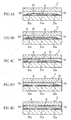
- the sample liquid B moves through the capillary 6 toward the opening 61 by capillary action, as shown in Figs. 4A-4D, and eventually fills the internal space of the capillary 6, as shown in Fig. 4E.
- the sample liquid B dissolves the reagent portion 35 to form a liquid phase reaction system in the capillary 6.
- oxidation-reduction reaction occurs to produce a reaction product in accordance with the amount of the component to be measured.
- glucose is oxidized, while the electron carrier is reduced.
- the reduced electron carrier releases the electrons.
- the electrons released from the electron carrier are supplied to the operative electrode 31.
- the controller 10 shown in Fig. 1 controls the operation of each of the units 12-17.
- the memory 11 stores programs and data necessary for operating the units 12-17.
- the data stored in the memory 11 may include that as to a calibration curve showing the relationship between a response current (or the voltage converted from the current) and the glucose level, and that as to correction values used for computing the concentration in the computation unit 16.
- the data as to correction values is stored in the form of a table or a formula as associated with the time taken from when liquid conduction is established between the end 31a of the operative electrode 31 and the 32a of the first counterpart electrode 32 till when liquid conduction is established between the end 31a of the operative electrode 31 and the 33a of the second counterpart electrode 33.
- the switching unit 12 includes a first switch 12a and a second switch 12b.
- the switches 12a and 12b are turned on and off individually by the controller 10.
- the voltage application unit 13 and the current measurer 14 are electrically connected to selected one or both of the first counterpart electrode 32 and the second counterpart electrode 33.
- the voltage application unit 13 serves to apply a voltage across the operative electrode 31 and the counterpart electrodes 32, 33.
- the voltage application unit 13 includes a DC power source such as a dry cell or a rechargeable battery.
- the current measurer 14 measures the response current when a voltage is applied across the operative electrode 31 and at least one of the counterpart electrodes 32, 33.
- the detector 15 detects whether or not liquid conduction is established between the ends 31a of the operative electrode 31 and the end 32a of the first counterpart electrode 32 or between the ends 31a of the operative electrode 31 and the end 33a of the second counterpart electrode 33 when the sample liquid is introduced into the capillary 6.
- the computation unit 16 computes the time taken from the occurrence of liquid conduction between the end 31a of the operative electrode 31 and the end 32a of the first counterpart electrode 32 to the occurrence of liquid conduction between the end 31a of the operative electrode 31 and the end 33a of the second counterpart electrode 33. Based on the computed time, the computation unit computes the correction value necessary for the computation of the concentration of the particular component in the sample liquid. The computation unit computes the concentration based on the correction value and the current measured by the current measurer 14.
- the display 17 is provided for displaying measurement results or an error message, for example.
- the display 17 may comprise a liquid crystal display, for example.
- Each of the controller 10, the memory 11, the detector 15 and the computation unit 16 may comprise one of a CPU, a ROM and a RAM or a combination of these components. Alternatively, all of the units 10, 11, 15 and 16 may be provided by connecting a plurality of memories to a single CPU.
- the biosensor 2 is mounted to the concentration measuring apparatus 1, and blood is introduced into the capillary 6 of the biosensor 2 through the opening 60 or the opening 61.
- the voltage application unit 13 applies a voltage across the operative electrode 31 and the first counterpart electrode 32 and across the operative electrode 31 and the second counterpart electrode 33 of the biosensor 2 (S1).
- the current measurer 14 measures the response current (S2).
- the detector 15 checks whether or not liquid conduction is established between the end 31a of the operative electrode 31 and the end 32a of the first counterpart electrode 32 or between the end 31a of the operative electrode 31 and the end 33a of the second counterpart electrode 33 (S3). Specifically, the detector 15 monitors the response current measured by the current measurer 14 and checks whether or not the response current exceeds a predetermined threshold value. When the response current exceeds the threshold value, the detector 15 determines that the interior of the capillary is in the state as shown in Fig. 4C, for example, and that liquid conduction is established (S3: YES). When the response current does not exceed the threshold value, the detector 15 determines that the interior of the capillary is in the state as shown in Fig. 4A or 4B, for example, and that liquid conduction is not provided (S3: NO).
- the current measurement in S2 and the check in S3 are repetitively performed until the detector 15 detects the liquid conduction (S3: YES).
- the measurement of the response current in S2 is performed every 0.05 to 0.2 seconds, for example.
- the controller 10 turns off one of the first switch 12a and the second switch 12b (S4). For instance, when the liquid conduction between the end 31a of the operative electrode 31 and the end 32a of the first counterpart electrode 32 is detected, it is determined that the blood introduction into the capillary 6 is performed through the opening 61. In this case, the controller turns off the first switch 12a. In this state, voltage application and current measurement using the operative electrode 31 and the second counterpart electrode 33 is possible.
- the controller turns off the second switch 12b. In this state, voltage application and current measurement using the operative electrode 31 and the first counterpart electrode 32 is possible.
- the current measurer 14 measures the response current (S5), and the detector 15 checks the liquid conduction again (S6). Specifically, in the case where the liquid conduction between the end 31a of the operative electrode 31 and the end 32a of the first counterpart electrode 32 is detected in S3, the detector checks, in S6, whether or not liquid conduction is established between the end 31a of the operative electrode 31 and the end 33a of the second counterpart electrode 33.
- the detector checks, in S6, whether or not liquid conduction is established between the end 31a of the operative electrode 31 and the end 32a of the first counterpart electrode 32.
- S6 the determination of whether or not the liquid conduction is established and the process when the liquid conduction is not detected (S6: NO) are performed similarly to S3.
- the computation unit 16 computes the time taken from the detection of the liquid conduction in S3 (See Fig. 4C) to the detection of the liquid conduction in S6 (See Fig. 4D) (S7), and computes the correction value based on the computed time (S8).
- the correction value is computed based on a lookup table stored in the memory 11 and showing the relationship between the time taken and correction values.
- the correction value may be one for correcting the response current (or the voltage converted from the current) or one for correcting the value obtained by computation using a calibration curve.
- the controller 10 turns on the switch 12a (or 12b) which has turned off in S4, and the current measurer 14 measures the response current for the concentration computation (S11). It is to be noted that the switch 12a (or 12b) which has turned off in S4 need not necessarily be turned on in the current measurement in S11. The measurement of response current may be performed at predetermined intervals after the liquid conduction is detected in S6.
- the response current at a certain time after the detection of liquid conduction in S6 may be sampled and used as the response current for the computation.
- the measurement of the response current for the computation in S11 may be performed after a predetermined time has elapsed since the electrical conduction was detected in S3.
- the computation unit 16 computes the blood glucose level based on the response current for the computation and the correction value (S12).
- the computation of the blood glucose level is performed by using a calibration curve showing the relationship between the response current (or the voltage converted from the current) and the blood glucose level, for example.
- the computation result is displayed at the display 17 (S13).
- the sample liquid contains blood cell components in addition to the component to be measured.
- the proportion of blood cell components in the blood which is represented as hematocrit, influences the measurement result.
- hematocrit increases, the viscosity of the blood increases, whereby the travel speed of the blood through the capillary 6 decreases. Therefore, when the blood glucose level is computed taking the travel speed of the blood through the capillary into consideration, a proper value which compensates for the influence of hematocrit can be obtained.
- the travel speed of the blood is found out in the concentration measuring apparatus 1 by measuring the time taken from the occurrence of liquid conduction between the end 31a of the operative electrode 31 and the end 32a of the first counterpart electrode 32 to the occurrence of liquid conduction between the end 31a of the operative electrode 31 and the end 33a of the second counterpart electrode 33, for example. Therefore, it is not necessary to measure the hematocrit in advance or to input the hematocrit value into the concentration measuring apparatus 1. Therefore, it is possible to obtain a proper measurement result which compensates for the influence of hematocrit while reducing the burden posed on the measurer or user in performing the measurement.
- Figs. 6-10 illustrate a second embodiment of the present invention.
- parts or elements which are identical or similar to those of the foregoing embodiment are designated by the same reference signs as those used for the foregoing embodiment, and detailed description thereof will be omitted.
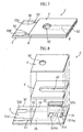
- the biosensor 2' includes a substrate 3', a spacer 4' and a cover 5', and a capillary 6' defined by these parts.
- the substrate 3' has an upper surface 30' formed with an operative electrode 31' and a counterpart electrode 32'. Most part of the operative electrode 31' extends longitudinally of the substrate 3', but an end 31a' thereof extends widthwise of the substrate 3'. Most part of the counterpart electrode 32' extends longitudinally of the substrate 3'.
- the counterpart electrode 32' has an end 32A provided with a first extension 32Aa and a second extensions 32Ab which extend widthwise of the substrate.
- the second extension 32Ab is larger in surface area than the first extension 32Aa.
- the first extension 32Aa and the second extension 32Ab may be made generally equal to each other in surface area.
- the end 31a' of the operative electrode 31' is located between the first extension 32Aa and the second extension 32Ab.
- the first extension 32Aa, the end 31a' and the second extension 32Ab are spaced from each other longitudinally of the substrate 3.
- a reagent portion 35 is provided on the portions 31a', 32Aa and 32Ab to connect these portions to each other.
- the spacer 4' serves to define the height of the capillary 6'.
- the spacer 4' is formed with a slit 40' having an open end.
- the slit 40' defines the width of the capillary 6', and the open end of the slit 40' constitutes an introduction port 60' for introducing the sample liquid into the capillary 6'.
- the cover 5' is formed with a discharge port 50'.
- the discharge port 50' communicates with the inside of the capillary 6' and serves to discharge air from the inside of the capillary 6' to the outside.
- the concentration measuring apparatus 1' shown in Fig. 6 includes a controller 10, a memory 11, a voltage application unit 13, a current measurer 14, a detector 15, a computation unit 16 and a display 17.
- the concentration measuring apparatus 1' shown in Fig. 6 is not provided with a switching unit, because only the single counterpart electrode 32' is provided in the biosensor 2', as shown in Figs. 7 and 8. Part of the programs and data stored in the memory 11 of the concentration measuring apparatus 1' differs from those of the concentration measuring apparatus 1 (See Fig. 1).
- the biosensor 2' is mounted to the concentration measuring apparatus 1', and blood is introduced into the capillary 6' of the biosensor 2' through the introduction port 60'.
- the voltage application unit 13 applies a voltage across the operative electrode 31' and the counterpart electrode 32' of the biosensor 2' (S21).
- the current measurer 14 measures a response current (S22). Based on the response current, it is determined whether or not liquid conduction is established between the end 31a' of the operative electrode 31' and the first extension 32Aa of the counterpart electrode 32' (S23).
- the detector 15 monitors the response current measured by the current measurer 12 and checks whether or not the response current exceeds a predetermined threshold value. When the response current exceeds the threshold value, the detector 15 determines that liquid conduction is established between the end 31a' of the operative electrode 31' and the first extension 32Aa of the counterpart electrode 32' (S23: YES). When the response current does not exceed the threshold value, the detector determines that the liquid is not provided (S23: NO).
- the current measurement in S22 and the check in S23 are repetitively performed until the detector 15 detects the liquid conduction (S23: YES).
- the measurement of response current in S22 is performed every 0.05 to 0.2 seconds, for example.
- the detector 15 determines that the blood has entered the capillary 6' and checks whether or not liquid conduction is established between the end 31a' of the operative electrode 31' and the second extension 32Ab of the counterpart electrode 32' (S24). By the process step S24, it is determined whether or not a sufficient amount of blood needed for measurement is supplied to the interior of the capillary 6'.
- the liquid conduction detection process in S24 is performed following the flowchart shown in Fig. 10, for example.
- the current measurer 14 measures the response current at predetermined intervals.
- a response current value A is obtained in the first measurement (S31), and a response current value B is obtained in the next sampling (S32).
- the response current value A is subtracted from the response current value B to figure out the increase ⁇ (S33).
- a response current value C is obtained in the next sampling (S34).
- the response current value B is subtracted from the response current value C to figure out the increase ⁇ (S35).
- whether or not the difference between the increase ⁇ and the increase ⁇ is greater than a predetermined threshold value ⁇ is determined (S36).
- the detector 15 determines that the liquid conduction is established between the end 31a' of the operative electrode 31' and the second extension 32Ab of the counterpart electrode 32' (S37).
- the detector 15 determines that the liquid conduction is not provided. In this case, the process steps S31-S36 are repeated while using the current value C (S38) as the value B, using the increase ⁇ as the increase ⁇ (S39) and obtaining the next measurement value.
- the second extension 32Ab of the biosensor 2' is larger in surface area than the first extension 32Aa. Therefore, when the blood reaches the second extension 32Ab, the response current value changes largely. Therefore, in the liquid conduction detection process of S24, the liquid conduction between the end 31a' of the operative electrode 31' and the second extension 32Ab of the counterpart electrode 32' can be easily and reliably detected from the sharp change in the response current.
- the detector 15 obtains the response current value when the liquid conduction is confirmed in S24 (S37).
- the response current value is stored in the memory 11, for example.
- the detector 15 checks, in Step S26, whether or not a predetermined time has elapsed since the liquid conduction was confirmed in S24 (S37). This check is repetitively performed until the detector 15 determines that the predetermined time has elapsed (S26: YES).
- the current measurer 14 measures the response current for the concentration computation (S27).
- the response current may be measured at predetermined intervals after the liquid conduction is confirmed in S24 (S37).
- the response current at a certain time after the detection of liquid conduction in S24 may be sampled and used as the response current for computation.
- the obtaining of the response current for computation in S27 may be performed after a predetermined time has elapsed since the liquid conduction was detected in S23.
- the computation unit 16 computes the blood glucose level (S28). Specifically, for example, the difference between the response current for computation measured in S27 and the response current measured in S25 is computed, and the blood glucose level is computed utilizing the difference and the calibration curve stored in the memory 11. The computation result is displayed at the display 17 (S29).
- the liquid conduction between the end 31a' of the operative electrode 31' and the second extension 32Ab of the counterpart electrode 32' is detected based on the increase of the response current (S36).
- the liquid conduction is detected based on the relative comparison between response current values obtained by measurement, not based on the absolute comparison between a predetermined threshold value and a response current value. Therefore, even when the response current values are influenced by hematocrit, the detection of liquid conduction can be performed accurately without being influenced by hematocrit. Accordingly, whether or not a sufficient amount of blood necessary for measurement is supplied to the capillary 6' can be detected reliably.
- the computation of the blood glucose level in S28 is performed based on the difference between the response current measured in S27 and the response current measured in S25. Since this difference is also a value obtained by relative comparison, the computation provides proper concentration value which is free from the influence of hematocrit.
- the correction similar to that of the first embodiment may be performed. Specifically, the time taken from the detection of liquid conduction between the end 31a' of the operative electrode 31' and the first extension 32Aa of the counterpart electrode 32' in S23 to the confirmation of liquid conduction between the end 31a' of the operative electrode 31' and the second extension 32Ab of the counterpart electrode 32' in S24 (S37) may be computed, and correction may be performed based on the time taken.
- the present invention is not limited to the first embodiment and the second embodiment described above.
- the invention is applicable to a sample liquid other than blood, e.g. urine.
- the method of the present invention is applicable for measuring a component other than glucose, e.g. cholesterol.
- the amount of chyle or the degree of hemolysis of the sample liquid may be taken into consideration as a factor which influences the response current in the concentration measurement of the present invention.
Landscapes
- Health & Medical Sciences (AREA)
- Chemical & Material Sciences (AREA)
- Hematology (AREA)
- Life Sciences & Earth Sciences (AREA)
- Analytical Chemistry (AREA)
- Chemical Kinetics & Catalysis (AREA)
- Electrochemistry (AREA)
- Physics & Mathematics (AREA)
- Molecular Biology (AREA)
- Biochemistry (AREA)
- General Health & Medical Sciences (AREA)
- General Physics & Mathematics (AREA)
- Immunology (AREA)
- Pathology (AREA)
- Investigating Or Analysing Biological Materials (AREA)
- Investigating Or Analyzing Materials By The Use Of Electric Means (AREA)
Abstract
Description
Claims (19)
- A concentration measuring method for measuring concentration of a particular component in a sample liquid using a test tool;
the test tool comprising: a capillary for moving the sample liquid, and a first through third detection elements for measuring an electro-physical quantity, the first through the third detection elements being arranged in the mentioned order from an upstream side toward a downstream side in a moving direction of the sample liquid;
wherein the method comprises:a first detection step for detecting whether or not liquid conduction is established between the first detection element and the second detection element;a second detection step for detecting whether or not liquid conduction is established between the second detection element and the third detection element;a measurement step for measuring an electro-physical quantity for computation by using at least two of the first through the third detection elements; anda concentration computation step for computing the concentration of the particular component based on the electro-physical quantity for computation. - The concentration measuring method according to claim 1, further comprising a time computation step for computing time taken from the detection of liquid conduction in the first detection step to the detection of liquid conduction in the second conduction step;
wherein the concentration computation step comprises computing the concentration of the particular component while taking the computed time into consideration. - The concentration measuring method according to claim 2, wherein the concentration computation step includes data processing operation for correcting, based on a correction value, an electro-physical quantity for computation or a computed value obtained based on the electro-physical quantity for computation; and
wherein the correction value is obtained by computation based on data showing a relationship between the time taken and the correction value. - The concentration measuring method according to claim 1, wherein the second detection step comprises measuring an electro-physical quantity by using all of the first through the third detection elements and determining whether or not liquid conduction is established between the second detection element and the third detection element based on a time history of the electro-physical quantity.
- The concentration measuring method according to claim 4, wherein the second detection step comprises measuring an electro-physical quantity at a plurality of predetermined measurement time points, computing a variation in current per unit time at each of the measurement time points, and determining that liquid conduction is established between the second detection element and the third detection element when the variation in current is greater than a predetermined threshold value.
- The concentration measuring method according to claim 4, wherein the second detection step comprises computing a difference between an electro-physical quantity measured at a certain measurement time point and an electro-physical quantity measured at another measurement time point directly before said certain measurement time point and determining that liquid conduction is established-between the second detection element and the third detection element when the difference is greater than a predetermined threshold value.
- The concentration measuring method according to claim 4, wherein the third detection element is larger in surface area than the first detection element in the test tool.
- The concentration measuring method according to claim 4, wherein the concentration computation step comprises computing the concentration of the particular component based on a difference between an electro-physical quantity measured after a predetermined time has elapsed since liquid conduction between the second detection element and the third detection element was detected in the second detection step and another electro-physical quantity measured when liquid conduction between the second detection element and the third detection element is detected in the second step.
- The concentration measuring method according to claim 4, further comprising a time computation step for computing time taken from the detection of liquid conduction in the first detection step to the detection of liquid conduction in the second conduction step;
wherein the concentration computation step comprises computing the concentration of the particular component while taking the computed time into consideration. - The concentration measuring method according to claim 2, wherein the sample liquid contains a coexisting component which causes an error in the concentration measurement of the particular component; and
wherein the time taken is figured out as a reflection of influence of the coexisting component. - The concentration measuring method according to claim 10, wherein the sample liquid is blood containing blood cell components as the coexisting component.
- The concentration measuring method according to claim 11, wherein the particular component is glucose.
- A concentration measuring apparatus for measuring concentration of a particular component in a sample liquid using a test tool;
the test tool comprising: a capillary for moving the sample liquid, and a first through a third detection elements for measuring an electro-physical quantity, the first through the third detection elements being arranged in the mentioned order from an upstream side toward a downstream side in a moving direction of the sample liquid;
wherein the apparatus comprises:a detector for detecting whether or not liquid conduction is established between the first detection element and the second detection element as well as between the second detection element and the third detection element;an electro-physical quantity measurer for measuring an electro-physical quantity for computation by using at least two of the first through the third detection elements; anda computation unit for computing the concentration of the particular component based on the electro-physical quantity for computation. - The concentration measuring apparatus according to claim 13, further comprising a voltage application unit for applying a voltage across at least two detection elements selected from the first through the third detection elements;
wherein the electro-physical quantity measurer measures a current as the electro-physical quantity when the voltage application means applies the voltage. - The concentration measuring apparatus according to claim 13, wherein the computation unit computes time taken from the establishment of liquid conduction between the first detection element and the second detection element to the establishment of liquid conduction between the second detection element and the third detection element and computes the concentration of the particular component while taking the computed time into consideration.
- The concentration measuring apparatus according to claim 13, wherein the electro-physical quantity measurer measures an electro-physical quantity at a plurality of measurement time points with predetermined intervals, and
wherein the detector determines whether or not liquid conduction is established between the second detection element and the third detection element based on a time-course of the electro-physical quantity. - The concentration measuring apparatus according to claim 16, wherein the detector computes a variation in current per unit time at each of the measurement time points and determines that liquid conduction is established between the second detection element and the third detection element when the variation in current is greater than a predetermined threshold value.
- The concentration measuring apparatus according to claim 16, wherein the detector computes a difference between an electro-physical quantity measured at a certain measurement time point and an electro-physical quantity measured at another measurement time point directly before said certain measurement time point and determines that liquid conduction is established between the second detection element and the third detection element when the difference is greater than a predetermined threshold value.
- The concentration measuring apparatus according to claim 16, wherein the computation unit computes the concentration of the particular component based on a difference between an electro-physical quantity measured after a predetermined time has elapsed since liquid conduction between the second detection element and the third detection element was detected by the detector and another electro-physical quantity measured when liquid conduction between the second detection element and the third detection element is detected by the detector.
Applications Claiming Priority (5)
| Application Number | Priority Date | Filing Date | Title |
|---|---|---|---|
| JP2001315553 | 2001-10-12 | ||
| JP2001315553 | 2001-10-12 | ||
| JP2001315552 | 2001-10-12 | ||
| JP2001315552 | 2001-10-12 | ||
| PCT/JP2002/010505 WO2003034055A1 (en) | 2001-10-12 | 2002-10-09 | Concentration measuring method and concentration measuring device |
Publications (3)
| Publication Number | Publication Date |
|---|---|
| EP1443322A1 true EP1443322A1 (en) | 2004-08-04 |
| EP1443322A4 EP1443322A4 (en) | 2005-02-02 |
| EP1443322B1 EP1443322B1 (en) | 2013-07-17 |
Family
ID=26623876
Family Applications (1)
| Application Number | Title | Priority Date | Filing Date |
|---|---|---|---|
| EP02775306.0A Expired - Lifetime EP1443322B1 (en) | 2001-10-12 | 2002-10-09 | Concentration measuring method and concentration measuring device |
Country Status (5)
| Country | Link |
|---|---|
| US (1) | US7491310B2 (en) |
| EP (1) | EP1443322B1 (en) |
| JP (1) | JP4246633B2 (en) |
| CN (1) | CN100367030C (en) |
| WO (1) | WO2003034055A1 (en) |
Cited By (9)
| Publication number | Priority date | Publication date | Assignee | Title |
|---|---|---|---|---|
| EP1746413A2 (en) | 2005-07-19 | 2007-01-24 | Hypoguard Limited | Electrochemical Biosensor and method of manufacture |
| EP1772728A1 (en) * | 2005-10-05 | 2007-04-11 | Roche Diagnostics GmbH | Method and system for testing electrochemical sensors |
| WO2009125930A1 (en) * | 2008-04-08 | 2009-10-15 | All Medicus Co.,Ltd. | Bio-sensor |
| EP1707953A4 (en) * | 2003-12-04 | 2009-12-23 | Panasonic Corp | HEMATOCRITE MEASUREMENT METHOD (HCT), SENSOR USED THEREFOR, AND MEASURING INSTRUMENT |
| EP2239563A1 (en) * | 2009-04-09 | 2010-10-13 | Bionime Corporation | Method for estimating distribution of sample |
| CN101887047A (en) * | 2009-05-12 | 2010-11-17 | 华广生技股份有限公司 | Detection method for judging sample full condition |
| US7955492B2 (en) | 2004-04-19 | 2011-06-07 | Panasonic Corporation | Method for measuring blood components and biosensor and measuring instrument for use therein |
| EP1927850A4 (en) * | 2005-09-14 | 2011-09-14 | Sumitomo Electric Industries | BIOSENSOR MEASURING DEVICE, BIOSENSOR MEASURING SYSTEM AND BIOSENSOR MEASURING PROCEDURES |
| US8535497B2 (en) | 2003-12-04 | 2013-09-17 | Panasonic Corporation | Method of measuring blood component, sensor used in the method, and measuring device |
Families Citing this family (95)
| Publication number | Priority date | Publication date | Assignee | Title |
|---|---|---|---|---|
| US6036924A (en) | 1997-12-04 | 2000-03-14 | Hewlett-Packard Company | Cassette of lancet cartridges for sampling blood |
| US6391005B1 (en) | 1998-03-30 | 2002-05-21 | Agilent Technologies, Inc. | Apparatus and method for penetration with shaft having a sensor for sensing penetration depth |
| US8641644B2 (en) | 2000-11-21 | 2014-02-04 | Sanofi-Aventis Deutschland Gmbh | Blood testing apparatus having a rotatable cartridge with multiple lancing elements and testing means |
| EP2388587B1 (en) * | 2000-11-30 | 2018-01-10 | Panasonic Healthcare Holdings Co., Ltd. | Method of quantifying substrate |
| US7981056B2 (en) | 2002-04-19 | 2011-07-19 | Pelikan Technologies, Inc. | Methods and apparatus for lancet actuation |
| ES2336081T3 (en) | 2001-06-12 | 2010-04-08 | Pelikan Technologies Inc. | SELF-OPTIMIZATION PUNCTURE DEVICE WITH MEANS OF ADAPTATION TO TEMPORARY VARIATIONS IN CUTANEOUS PROPERTIES. |
| US7041068B2 (en) | 2001-06-12 | 2006-05-09 | Pelikan Technologies, Inc. | Sampling module device and method |
| ATE497731T1 (en) | 2001-06-12 | 2011-02-15 | Pelikan Technologies Inc | DEVICE FOR INCREASING THE SUCCESS RATE OF BLOOD YIELD OBTAINED BY A FINGER PICK |
| AU2002348683A1 (en) | 2001-06-12 | 2002-12-23 | Pelikan Technologies, Inc. | Method and apparatus for lancet launching device integrated onto a blood-sampling cartridge |
| US9226699B2 (en) | 2002-04-19 | 2016-01-05 | Sanofi-Aventis Deutschland Gmbh | Body fluid sampling module with a continuous compression tissue interface surface |
| CA2448681C (en) | 2001-06-12 | 2014-09-09 | Pelikan Technologies, Inc. | Integrated blood sampling analysis system with multi-use sampling module |
| US8337419B2 (en) | 2002-04-19 | 2012-12-25 | Sanofi-Aventis Deutschland Gmbh | Tissue penetration device |
| AU2002312521A1 (en) | 2001-06-12 | 2002-12-23 | Pelikan Technologies, Inc. | Blood sampling apparatus and method |
| US9427532B2 (en) | 2001-06-12 | 2016-08-30 | Sanofi-Aventis Deutschland Gmbh | Tissue penetration device |
| US9795747B2 (en) | 2010-06-02 | 2017-10-24 | Sanofi-Aventis Deutschland Gmbh | Methods and apparatus for lancet actuation |
| ATE485766T1 (en) | 2001-06-12 | 2010-11-15 | Pelikan Technologies Inc | ELECTRICAL ACTUATING ELEMENT FOR A LANCET |
| US7344894B2 (en) | 2001-10-16 | 2008-03-18 | Agilent Technologies, Inc. | Thermal regulation of fluidic samples within a diagnostic cartridge |
| US8267870B2 (en) | 2002-04-19 | 2012-09-18 | Sanofi-Aventis Deutschland Gmbh | Method and apparatus for body fluid sampling with hybrid actuation |
| US8579831B2 (en) | 2002-04-19 | 2013-11-12 | Sanofi-Aventis Deutschland Gmbh | Method and apparatus for penetrating tissue |
| US7175642B2 (en) | 2002-04-19 | 2007-02-13 | Pelikan Technologies, Inc. | Methods and apparatus for lancet actuation |
| US9314194B2 (en) | 2002-04-19 | 2016-04-19 | Sanofi-Aventis Deutschland Gmbh | Tissue penetration device |
| US8784335B2 (en) | 2002-04-19 | 2014-07-22 | Sanofi-Aventis Deutschland Gmbh | Body fluid sampling device with a capacitive sensor |
| US7976476B2 (en) | 2002-04-19 | 2011-07-12 | Pelikan Technologies, Inc. | Device and method for variable speed lancet |
| US7226461B2 (en) | 2002-04-19 | 2007-06-05 | Pelikan Technologies, Inc. | Method and apparatus for a multi-use body fluid sampling device with sterility barrier release |
| US8360992B2 (en) | 2002-04-19 | 2013-01-29 | Sanofi-Aventis Deutschland Gmbh | Method and apparatus for penetrating tissue |
| US7244265B2 (en) | 2002-04-19 | 2007-07-17 | Pelikan Technologies, Inc. | Method and apparatus for penetrating tissue |
| US7563232B2 (en) | 2002-04-19 | 2009-07-21 | Pelikan Technologies, Inc. | Method and apparatus for penetrating tissue |
| US7229458B2 (en) | 2002-04-19 | 2007-06-12 | Pelikan Technologies, Inc. | Method and apparatus for penetrating tissue |
| US7331931B2 (en) | 2002-04-19 | 2008-02-19 | Pelikan Technologies, Inc. | Method and apparatus for penetrating tissue |
| US7297122B2 (en) | 2002-04-19 | 2007-11-20 | Pelikan Technologies, Inc. | Method and apparatus for penetrating tissue |
| US8372016B2 (en) | 2002-04-19 | 2013-02-12 | Sanofi-Aventis Deutschland Gmbh | Method and apparatus for body fluid sampling and analyte sensing |
| US9248267B2 (en) | 2002-04-19 | 2016-02-02 | Sanofi-Aventis Deustchland Gmbh | Tissue penetration device |
| US7232451B2 (en) | 2002-04-19 | 2007-06-19 | Pelikan Technologies, Inc. | Method and apparatus for penetrating tissue |
| US7524293B2 (en) | 2002-04-19 | 2009-04-28 | Pelikan Technologies, Inc. | Method and apparatus for penetrating tissue |
| US7491178B2 (en) | 2002-04-19 | 2009-02-17 | Pelikan Technologies, Inc. | Method and apparatus for penetrating tissue |
| US7371247B2 (en) | 2002-04-19 | 2008-05-13 | Pelikan Technologies, Inc | Method and apparatus for penetrating tissue |
| US7141058B2 (en) | 2002-04-19 | 2006-11-28 | Pelikan Technologies, Inc. | Method and apparatus for a body fluid sampling device using illumination |
| US7909778B2 (en) | 2002-04-19 | 2011-03-22 | Pelikan Technologies, Inc. | Method and apparatus for penetrating tissue |
| US7582099B2 (en) | 2002-04-19 | 2009-09-01 | Pelikan Technologies, Inc | Method and apparatus for penetrating tissue |
| US7291117B2 (en) | 2002-04-19 | 2007-11-06 | Pelikan Technologies, Inc. | Method and apparatus for penetrating tissue |
| EP1501402A4 (en) | 2002-04-19 | 2008-07-02 | Pelikan Technologies Inc | DEVICE AND METHOD FOR USING A VARIABLE SPEED LANCET |
| US7485128B2 (en) | 2002-04-19 | 2009-02-03 | Pelikan Technologies, Inc. | Method and apparatus for penetrating tissue |
| US7410468B2 (en) | 2002-04-19 | 2008-08-12 | Pelikan Technologies, Inc. | Method and apparatus for penetrating tissue |
| US7674232B2 (en) | 2002-04-19 | 2010-03-09 | Pelikan Technologies, Inc. | Method and apparatus for penetrating tissue |
| US8221334B2 (en) | 2002-04-19 | 2012-07-17 | Sanofi-Aventis Deutschland Gmbh | Method and apparatus for penetrating tissue |
| US8702624B2 (en) | 2006-09-29 | 2014-04-22 | Sanofi-Aventis Deutschland Gmbh | Analyte measurement device with a single shot actuator |
| US7374544B2 (en) | 2002-04-19 | 2008-05-20 | Pelikan Technologies, Inc. | Method and apparatus for penetrating tissue |
| US7648468B2 (en) | 2002-04-19 | 2010-01-19 | Pelikon Technologies, Inc. | Method and apparatus for penetrating tissue |
| US7892183B2 (en) | 2002-04-19 | 2011-02-22 | Pelikan Technologies, Inc. | Method and apparatus for body fluid sampling and analyte sensing |
| US7547287B2 (en) | 2002-04-19 | 2009-06-16 | Pelikan Technologies, Inc. | Method and apparatus for penetrating tissue |
| US7901362B2 (en) | 2002-04-19 | 2011-03-08 | Pelikan Technologies, Inc. | Method and apparatus for penetrating tissue |
| US9795334B2 (en) | 2002-04-19 | 2017-10-24 | Sanofi-Aventis Deutschland Gmbh | Method and apparatus for penetrating tissue |
| US7717863B2 (en) | 2002-04-19 | 2010-05-18 | Pelikan Technologies, Inc. | Method and apparatus for penetrating tissue |
| US8574895B2 (en) | 2002-12-30 | 2013-11-05 | Sanofi-Aventis Deutschland Gmbh | Method and apparatus using optical techniques to measure analyte levels |
| EP1628567B1 (en) | 2003-05-30 | 2010-08-04 | Pelikan Technologies Inc. | Method and apparatus for fluid injection |
| EP1633235B1 (en) | 2003-06-06 | 2014-05-21 | Sanofi-Aventis Deutschland GmbH | Apparatus for body fluid sampling and analyte sensing |
| WO2006001797A1 (en) | 2004-06-14 | 2006-01-05 | Pelikan Technologies, Inc. | Low pain penetrating |
| US7604592B2 (en) | 2003-06-13 | 2009-10-20 | Pelikan Technologies, Inc. | Method and apparatus for a point of care device |
| EP1671096A4 (en) | 2003-09-29 | 2009-09-16 | Pelikan Technologies Inc | METHOD AND APPARATUS FOR AN IMPROVED SAMPLING INTERFERENCE DEVICE |
| US9351680B2 (en) | 2003-10-14 | 2016-05-31 | Sanofi-Aventis Deutschland Gmbh | Method and apparatus for a variable user interface |
| US7822454B1 (en) | 2005-01-03 | 2010-10-26 | Pelikan Technologies, Inc. | Fluid sampling device with improved analyte detecting member configuration |
| EP1706026B1 (en) | 2003-12-31 | 2017-03-01 | Sanofi-Aventis Deutschland GmbH | Method and apparatus for improving fluidic flow and sample capture |
| WO2005114164A2 (en) * | 2004-05-14 | 2005-12-01 | Bayer Healthcare Llc | Voltammetric systems for assaying biological analytes |
| WO2006011062A2 (en) | 2004-05-20 | 2006-02-02 | Albatros Technologies Gmbh & Co. Kg | Printable hydrogel for biosensors |
| US9775553B2 (en) | 2004-06-03 | 2017-10-03 | Sanofi-Aventis Deutschland Gmbh | Method and apparatus for a fluid sampling device |
| WO2005120365A1 (en) | 2004-06-03 | 2005-12-22 | Pelikan Technologies, Inc. | Method and apparatus for a fluid sampling device |
| US8652831B2 (en) | 2004-12-30 | 2014-02-18 | Sanofi-Aventis Deutschland Gmbh | Method and apparatus for analyte measurement test time |
| KR100801905B1 (en) * | 2005-08-08 | 2008-02-12 | 주식회사 인포피아 | Apparatus and method for measuring sample reaction result of biosensor |
| US8066866B2 (en) * | 2005-10-17 | 2011-11-29 | Lifescan, Inc. | Methods for measuring physiological fluids |
| RU2441223C2 (en) * | 2006-05-03 | 2012-01-27 | БАЙЕР ХЕЛТКЭА ЭлЭлСи | System for detecting underfill state for electrochemical biosensor |
| JP4785611B2 (en) * | 2006-05-11 | 2011-10-05 | アークレイ株式会社 | Method and apparatus for measuring the concentration of a specific component in a blood sample |
| US8080153B2 (en) * | 2007-05-31 | 2011-12-20 | Abbott Diabetes Care Inc. | Analyte determination methods and devices |
| KR101001902B1 (en) * | 2007-09-27 | 2010-12-17 | 주식회사 필로시스 | Biosensor measurement result error correction method and device using the same |
| JP4811380B2 (en) * | 2007-09-28 | 2011-11-09 | パナソニック株式会社 | Measuring method using biosensor |
| WO2009126900A1 (en) | 2008-04-11 | 2009-10-15 | Pelikan Technologies, Inc. | Method and apparatus for analyte detecting device |
| US9375169B2 (en) | 2009-01-30 | 2016-06-28 | Sanofi-Aventis Deutschland Gmbh | Cam drive for managing disposable penetrating member actions with a single motor and motor and control system |
| JP4674283B2 (en) * | 2009-06-01 | 2011-04-20 | アークレイ株式会社 | Analytical tool and manufacturing method thereof |
| WO2011059670A1 (en) * | 2009-11-10 | 2011-05-19 | Bayer Healthcare Llc | Underfill recognition system for a biosensor |
| US8877034B2 (en) * | 2009-12-30 | 2014-11-04 | Lifescan, Inc. | Systems, devices, and methods for measuring whole blood hematocrit based on initial fill velocity |
| US8101065B2 (en) * | 2009-12-30 | 2012-01-24 | Lifescan, Inc. | Systems, devices, and methods for improving accuracy of biosensors using fill time |
| CN103003692B (en) | 2010-03-22 | 2015-01-14 | 拜尔健康护理有限责任公司 | Residual compensation for biosensors |
| US8965476B2 (en) | 2010-04-16 | 2015-02-24 | Sanofi-Aventis Deutschland Gmbh | Tissue penetration device |
| MX367439B (en) | 2010-06-07 | 2019-08-22 | Ascensia Diabetes Care Holdings Ag | Underfill management system for a biosensor. |
| BR112012031166A2 (en) | 2010-06-07 | 2018-02-27 | Bayer Healthcare Llc | slope-based compensation including secondary output signals |
| US9482636B2 (en) * | 2010-10-28 | 2016-11-01 | Panasonic Healthcare Holdings Co., Ltd. | Vital information measurement device and vital information measurement method employing same |
| EP3315123B1 (en) | 2011-09-21 | 2019-08-21 | Ascensia Diabetes Care Holdings AG | Analysis compensation including segmented signals |
| CN104407028B (en) * | 2014-11-27 | 2017-01-11 | 三诺生物传感股份有限公司 | Method and system for controlling test strip electrodes |
| ES2927989T3 (en) | 2017-11-21 | 2022-11-14 | Mx3 Diagnostics Inc | Saliva analysis system and procedure |
| US11067529B2 (en) | 2017-11-22 | 2021-07-20 | Jim Connolly | Multi-zone, fixed potential test sensor heating system |
| US11199551B1 (en) | 2017-11-22 | 2021-12-14 | Jim Connolly | Test sensors, systems, and analysis techniques for measuring glycated hemoglobin in undiluted blood samples |
| EP3864402A1 (en) | 2018-10-11 | 2021-08-18 | MX3 Diagnostics, Inc. | Ion selective sensor |
| US11701036B2 (en) | 2019-07-10 | 2023-07-18 | MX3 Diagnostics, Inc. | Saliva test strip and method |
| EP4090243A4 (en) * | 2020-01-15 | 2023-12-20 | MX3 Diagnostics, Inc. | EVALUATION OF THE CONCENTRATION OF BIOMARKERS IN A FLUID |
| US11703436B2 (en) | 2020-01-30 | 2023-07-18 | MX3 Diagnostics, Inc. | Biological fluid sample assessment |
| WO2025025107A1 (en) * | 2023-07-31 | 2025-02-06 | 深圳市理邦精密仪器股份有限公司 | Sample test card, testing assembly, and medical testing device |
Family Cites Families (11)
| Publication number | Priority date | Publication date | Assignee | Title |
|---|---|---|---|---|
| US5320732A (en) * | 1990-07-20 | 1994-06-14 | Matsushita Electric Industrial Co., Ltd. | Biosensor and measuring apparatus using the same |
| JP3135959B2 (en) | 1991-12-12 | 2001-02-19 | アークレイ株式会社 | Biosensor and separation and quantification method using the same |
| JP3189416B2 (en) * | 1992-09-25 | 2001-07-16 | 松下電器産業株式会社 | Liquid component measuring device |
| JPH0810208A (en) | 1994-06-30 | 1996-01-16 | Toshiba Corp | Dishwasher |
| US5650062A (en) * | 1995-03-17 | 1997-07-22 | Matsushita Electric Industrial Co., Ltd. | Biosensor, and a method and a device for quantifying a substrate in a sample liquid using the same |
| US5582697A (en) * | 1995-03-17 | 1996-12-10 | Matsushita Electric Industrial Co., Ltd. | Biosensor, and a method and a device for quantifying a substrate in a sample liquid using the same |
| US5628890A (en) * | 1995-09-27 | 1997-05-13 | Medisense, Inc. | Electrochemical sensor |
| JP3848993B2 (en) * | 1998-01-06 | 2006-11-22 | アークレイ株式会社 | Method and apparatus for measuring the amount of components in the presence of coexisting substances |
| US7312087B2 (en) * | 2000-01-11 | 2007-12-25 | Clinical Micro Sensors, Inc. | Devices and methods for biochip multiplexing |
| CA2305922C (en) * | 1999-08-02 | 2005-09-20 | Bayer Corporation | Improved electrochemical sensor design |
| JP2001330581A (en) | 2000-05-19 | 2001-11-30 | Matsushita Electric Ind Co Ltd | Substrate concentration determination method |
-
2002
- 2002-10-09 WO PCT/JP2002/010505 patent/WO2003034055A1/en not_active Ceased
- 2002-10-09 CN CNB028201507A patent/CN100367030C/en not_active Expired - Lifetime
- 2002-10-09 JP JP2003536740A patent/JP4246633B2/en not_active Expired - Lifetime
- 2002-10-09 EP EP02775306.0A patent/EP1443322B1/en not_active Expired - Lifetime
- 2002-10-09 US US10/492,432 patent/US7491310B2/en not_active Expired - Lifetime
Cited By (21)
| Publication number | Priority date | Publication date | Assignee | Title |
|---|---|---|---|---|
| US8480869B2 (en) | 2003-12-04 | 2013-07-09 | Panasonic Corporation | Method of measuring hematocrit (Hct), sensor used in the method, and measuring device |
| US9719956B2 (en) | 2003-12-04 | 2017-08-01 | Panasonic Healthcare Holdings Co., Ltd. | Method of measuring blood component, sensor used in the method, and measuring device |
| US9213012B2 (en) | 2003-12-04 | 2015-12-15 | Panasonic Healthcare Holdings Co., Ltd. | Method of measuring blood component, sensor used in the method, and measuring device |
| US8540864B2 (en) | 2003-12-04 | 2013-09-24 | Panasonic Corporation | Method of measuring blood component, sensor used in the method, and measuring device |
| EP1707953A4 (en) * | 2003-12-04 | 2009-12-23 | Panasonic Corp | HEMATOCRITE MEASUREMENT METHOD (HCT), SENSOR USED THEREFOR, AND MEASURING INSTRUMENT |
| US8535497B2 (en) | 2003-12-04 | 2013-09-17 | Panasonic Corporation | Method of measuring blood component, sensor used in the method, and measuring device |
| US8088271B2 (en) | 2003-12-04 | 2012-01-03 | Panasonic Corporation | Method of measuring hematocrit (Hct), sensor used in the method, and measuring device |
| US9285335B2 (en) | 2004-04-19 | 2016-03-15 | Panasonic Healthcare Holdings Co., Ltd. | Method for measuring blood components and biosensor and measuring instrument for use therein |
| US8524055B2 (en) | 2004-04-19 | 2013-09-03 | Panasonic Corporation | Method for measuring blood components and biosensor and measuring instrument for use therein |
| US7955492B2 (en) | 2004-04-19 | 2011-06-07 | Panasonic Corporation | Method for measuring blood components and biosensor and measuring instrument for use therein |
| EP1746413A3 (en) * | 2005-07-19 | 2007-02-21 | Hypoguard Limited | Electrochemical Biosensor and method of manufacture |
| EP1746413A2 (en) | 2005-07-19 | 2007-01-24 | Hypoguard Limited | Electrochemical Biosensor and method of manufacture |
| EP1927850A4 (en) * | 2005-09-14 | 2011-09-14 | Sumitomo Electric Industries | BIOSENSOR MEASURING DEVICE, BIOSENSOR MEASURING SYSTEM AND BIOSENSOR MEASURING PROCEDURES |
| US8282813B2 (en) | 2005-09-14 | 2012-10-09 | Sumitomo Electric Industries, Ltd. | Biosensor measurement machine, biosensor measurement system and biosensor measurement method |
| US7626401B2 (en) | 2005-10-05 | 2009-12-01 | Roche Diagnostics Operations, Inc. | Method and system for error checking an electrochemical sensor |
| US7429865B2 (en) | 2005-10-05 | 2008-09-30 | Roche Diagnostics Operations, Inc. | Method and system for error checking an electrochemical sensor |
| EP1772728A1 (en) * | 2005-10-05 | 2007-04-11 | Roche Diagnostics GmbH | Method and system for testing electrochemical sensors |
| WO2009125930A1 (en) * | 2008-04-08 | 2009-10-15 | All Medicus Co.,Ltd. | Bio-sensor |
| EP2239563A1 (en) * | 2009-04-09 | 2010-10-13 | Bionime Corporation | Method for estimating distribution of sample |
| US10197523B2 (en) | 2009-04-09 | 2019-02-05 | Bionime Corporation | Method for estimating distribution of sample |
| CN101887047A (en) * | 2009-05-12 | 2010-11-17 | 华广生技股份有限公司 | Detection method for judging sample full condition |
Also Published As
| Publication number | Publication date |
|---|---|
| US20040232009A1 (en) | 2004-11-25 |
| CN100367030C (en) | 2008-02-06 |
| JPWO2003034055A1 (en) | 2005-02-03 |
| CN1633596A (en) | 2005-06-29 |
| US7491310B2 (en) | 2009-02-17 |
| WO2003034055A1 (en) | 2003-04-24 |
| JP4246633B2 (en) | 2009-04-02 |
| EP1443322A4 (en) | 2005-02-02 |
| EP1443322B1 (en) | 2013-07-17 |
Similar Documents
| Publication | Publication Date | Title |
|---|---|---|
| US7491310B2 (en) | Concentration measuring method and concentration measuring apparatus | |
| JP4272524B2 (en) | Concentration measuring method and concentration measuring device for specific component | |
| EP2149792B1 (en) | Sample analyzing method | |
| EP2193367B1 (en) | Method for correcting erroneous results of measurement in biosensors and apparatus using the same | |
| US7749371B2 (en) | Method and apparatus for rapid electrochemical analysis | |
| CN101432620B (en) | Underfill detection system for electrochemical biosensor | |
| EP3395954B1 (en) | Rapid-read gated amperometry | |
| RU2647473C2 (en) | Systems and methods for improved stability of electrochemical sensors | |
| EP2678670B1 (en) | Capacitance detection in electrochemical assay with improved sampling time offset | |
| RU2594513C1 (en) | System and method for detecting used and dried sensors | |
| US9709521B2 (en) | System and method for measuring an analyte in a sample and correcting for interferents | |
| JPWO2002057768A1 (en) | Quantitative analysis method and quantitative analyzer using sensor | |
| US11733198B2 (en) | Method for determining analyte concentration in a sample | |
| US20180217079A1 (en) | Determining an analyte concentration of a physiological fluid having an interferent | |
| MXPA06008846A (en) | Electrochemical biosensor | |
| WO2021015759A1 (en) | Method for determining analyte concentration in a sample | |
| HK1153536A (en) | Method for rapid electrochemical analysis | |
| HK1153537A (en) | Method for rapid electrochemical analysis | |
| MXPA00005876A (en) | Sample detection to initiate timing of an electrochemical assay |
Legal Events
| Date | Code | Title | Description |
|---|---|---|---|
| PUAI | Public reference made under article 153(3) epc to a published international application that has entered the european phase |
Free format text: ORIGINAL CODE: 0009012 |
|
| 17P | Request for examination filed |
Effective date: 20040416 |
|
| AK | Designated contracting states |
Kind code of ref document: A1 Designated state(s): AT BE BG CH CY CZ DE DK EE ES FI FR GB GR IE IT LI LU MC NL PT SE SK TR |
|
| AX | Request for extension of the european patent |
Extension state: AL LT LV MK RO SI |
|
| A4 | Supplementary search report drawn up and despatched |
Effective date: 20041221 |
|
| RIC1 | Information provided on ipc code assigned before grant |
Ipc: 7G 01N 27/416 B Ipc: 7G 01N 27/327 A Ipc: 7G 01N 27/403 B Ipc: 7C 12Q 1/26 B Ipc: 7G 01N 33/487 B Ipc: 7C 12Q 1/00 B |
|
| 17Q | First examination report despatched |
Effective date: 20070921 |
|
| GRAP | Despatch of communication of intention to grant a patent |
Free format text: ORIGINAL CODE: EPIDOSNIGR1 |
|
| GRAS | Grant fee paid |
Free format text: ORIGINAL CODE: EPIDOSNIGR3 |
|
| GRAA | (expected) grant |
Free format text: ORIGINAL CODE: 0009210 |
|
| AK | Designated contracting states |
Kind code of ref document: B1 Designated state(s): AT BE BG CH CY CZ DE DK EE ES FI FR GB GR IE IT LI LU MC NL PT SE SK TR |
|
| REG | Reference to a national code |
Ref country code: GB Ref legal event code: FG4D |
|
| REG | Reference to a national code |
Ref country code: CH Ref legal event code: EP |
|
| REG | Reference to a national code |
Ref country code: IE Ref legal event code: FG4D |
|
| REG | Reference to a national code |
Ref country code: AT Ref legal event code: REF Ref document number: 622499 Country of ref document: AT Kind code of ref document: T Effective date: 20130815 |
|
| REG | Reference to a national code |
Ref country code: DE Ref legal event code: R082 Ref document number: 60245258 Country of ref document: DE Representative=s name: DEHNS, GB |
|
| REG | Reference to a national code |
Ref country code: DE Ref legal event code: R096 Ref document number: 60245258 Country of ref document: DE Effective date: 20130912 |
|
| REG | Reference to a national code |
Ref country code: AT Ref legal event code: MK05 Ref document number: 622499 Country of ref document: AT Kind code of ref document: T Effective date: 20130717 |
|
| REG | Reference to a national code |
Ref country code: NL Ref legal event code: VDEP Effective date: 20130717 |
|
| PG25 | Lapsed in a contracting state [announced via postgrant information from national office to epo] |
Ref country code: PT Free format text: LAPSE BECAUSE OF FAILURE TO SUBMIT A TRANSLATION OF THE DESCRIPTION OR TO PAY THE FEE WITHIN THE PRESCRIBED TIME-LIMIT Effective date: 20131118 Ref country code: CY Free format text: LAPSE BECAUSE OF FAILURE TO SUBMIT A TRANSLATION OF THE DESCRIPTION OR TO PAY THE FEE WITHIN THE PRESCRIBED TIME-LIMIT Effective date: 20130703 Ref country code: SE Free format text: LAPSE BECAUSE OF FAILURE TO SUBMIT A TRANSLATION OF THE DESCRIPTION OR TO PAY THE FEE WITHIN THE PRESCRIBED TIME-LIMIT Effective date: 20130717 Ref country code: BE Free format text: LAPSE BECAUSE OF FAILURE TO SUBMIT A TRANSLATION OF THE DESCRIPTION OR TO PAY THE FEE WITHIN THE PRESCRIBED TIME-LIMIT Effective date: 20130717 Ref country code: AT Free format text: LAPSE BECAUSE OF FAILURE TO SUBMIT A TRANSLATION OF THE DESCRIPTION OR TO PAY THE FEE WITHIN THE PRESCRIBED TIME-LIMIT Effective date: 20130717 |
|
| PG25 | Lapsed in a contracting state [announced via postgrant information from national office to epo] |
Ref country code: ES Free format text: LAPSE BECAUSE OF FAILURE TO SUBMIT A TRANSLATION OF THE DESCRIPTION OR TO PAY THE FEE WITHIN THE PRESCRIBED TIME-LIMIT Effective date: 20131028 Ref country code: NL Free format text: LAPSE BECAUSE OF FAILURE TO SUBMIT A TRANSLATION OF THE DESCRIPTION OR TO PAY THE FEE WITHIN THE PRESCRIBED TIME-LIMIT Effective date: 20130717 Ref country code: FI Free format text: LAPSE BECAUSE OF FAILURE TO SUBMIT A TRANSLATION OF THE DESCRIPTION OR TO PAY THE FEE WITHIN THE PRESCRIBED TIME-LIMIT Effective date: 20130717 Ref country code: GR Free format text: LAPSE BECAUSE OF FAILURE TO SUBMIT A TRANSLATION OF THE DESCRIPTION OR TO PAY THE FEE WITHIN THE PRESCRIBED TIME-LIMIT Effective date: 20131018 |
|
| PG25 | Lapsed in a contracting state [announced via postgrant information from national office to epo] |
Ref country code: CY Free format text: LAPSE BECAUSE OF FAILURE TO SUBMIT A TRANSLATION OF THE DESCRIPTION OR TO PAY THE FEE WITHIN THE PRESCRIBED TIME-LIMIT Effective date: 20130717 |
|
| PG25 | Lapsed in a contracting state [announced via postgrant information from national office to epo] |
Ref country code: EE Free format text: LAPSE BECAUSE OF FAILURE TO SUBMIT A TRANSLATION OF THE DESCRIPTION OR TO PAY THE FEE WITHIN THE PRESCRIBED TIME-LIMIT Effective date: 20130717 Ref country code: SK Free format text: LAPSE BECAUSE OF FAILURE TO SUBMIT A TRANSLATION OF THE DESCRIPTION OR TO PAY THE FEE WITHIN THE PRESCRIBED TIME-LIMIT Effective date: 20130717 Ref country code: CZ Free format text: LAPSE BECAUSE OF FAILURE TO SUBMIT A TRANSLATION OF THE DESCRIPTION OR TO PAY THE FEE WITHIN THE PRESCRIBED TIME-LIMIT Effective date: 20130717 Ref country code: DK Free format text: LAPSE BECAUSE OF FAILURE TO SUBMIT A TRANSLATION OF THE DESCRIPTION OR TO PAY THE FEE WITHIN THE PRESCRIBED TIME-LIMIT Effective date: 20130717 |
|
| PLBE | No opposition filed within time limit |
Free format text: ORIGINAL CODE: 0009261 |
|
| STAA | Information on the status of an ep patent application or granted ep patent |
Free format text: STATUS: NO OPPOSITION FILED WITHIN TIME LIMIT |
|
| PG25 | Lapsed in a contracting state [announced via postgrant information from national office to epo] |
Ref country code: MC Free format text: LAPSE BECAUSE OF FAILURE TO SUBMIT A TRANSLATION OF THE DESCRIPTION OR TO PAY THE FEE WITHIN THE PRESCRIBED TIME-LIMIT Effective date: 20130717 |
|
| REG | Reference to a national code |
Ref country code: CH Ref legal event code: PL |
|
| 26N | No opposition filed |
Effective date: 20140422 |
|
| REG | Reference to a national code |
Ref country code: IE Ref legal event code: MM4A |
|
| PG25 | Lapsed in a contracting state [announced via postgrant information from national office to epo] |
Ref country code: CH Free format text: LAPSE BECAUSE OF NON-PAYMENT OF DUE FEES Effective date: 20131031 Ref country code: LI Free format text: LAPSE BECAUSE OF NON-PAYMENT OF DUE FEES Effective date: 20131031 |
|
| REG | Reference to a national code |
Ref country code: DE Ref legal event code: R097 Ref document number: 60245258 Country of ref document: DE Effective date: 20140422 |
|
| PG25 | Lapsed in a contracting state [announced via postgrant information from national office to epo] |
Ref country code: IE Free format text: LAPSE BECAUSE OF NON-PAYMENT OF DUE FEES Effective date: 20131009 |
|
| PG25 | Lapsed in a contracting state [announced via postgrant information from national office to epo] |
Ref country code: TR Free format text: LAPSE BECAUSE OF FAILURE TO SUBMIT A TRANSLATION OF THE DESCRIPTION OR TO PAY THE FEE WITHIN THE PRESCRIBED TIME-LIMIT Effective date: 20130717 |
|
| PG25 | Lapsed in a contracting state [announced via postgrant information from national office to epo] |
Ref country code: LU Free format text: LAPSE BECAUSE OF NON-PAYMENT OF DUE FEES Effective date: 20131009 Ref country code: BG Free format text: LAPSE BECAUSE OF FAILURE TO SUBMIT A TRANSLATION OF THE DESCRIPTION OR TO PAY THE FEE WITHIN THE PRESCRIBED TIME-LIMIT Effective date: 20130717 |
|
| REG | Reference to a national code |
Ref country code: FR Ref legal event code: PLFP Year of fee payment: 14 |
|
| REG | Reference to a national code |
Ref country code: FR Ref legal event code: PLFP Year of fee payment: 15 |
|
| REG | Reference to a national code |
Ref country code: FR Ref legal event code: PLFP Year of fee payment: 16 |
|
| REG | Reference to a national code |
Ref country code: FR Ref legal event code: PLFP Year of fee payment: 17 |
|
| REG | Reference to a national code |
Ref country code: DE Ref legal event code: R082 Ref document number: 60245258 Country of ref document: DE |
|
| PGFP | Annual fee paid to national office [announced via postgrant information from national office to epo] |
Ref country code: GB Payment date: 20211022 Year of fee payment: 20 Ref country code: DE Payment date: 20211020 Year of fee payment: 20 |
|
| PGFP | Annual fee paid to national office [announced via postgrant information from national office to epo] |
Ref country code: IT Payment date: 20211028 Year of fee payment: 20 Ref country code: FR Payment date: 20211021 Year of fee payment: 20 |
|
| REG | Reference to a national code |
Ref country code: DE Ref legal event code: R071 Ref document number: 60245258 Country of ref document: DE |
|
| REG | Reference to a national code |
Ref country code: GB Ref legal event code: PE20 Expiry date: 20221008 |
|
| PG25 | Lapsed in a contracting state [announced via postgrant information from national office to epo] |
Ref country code: GB Free format text: LAPSE BECAUSE OF EXPIRATION OF PROTECTION Effective date: 20221008 |