EP1443269A1 - Fixing structure of refractory tile for protecting water tube and refractory structure for protecting water tube - Google Patents
Fixing structure of refractory tile for protecting water tube and refractory structure for protecting water tube Download PDFInfo
- Publication number
- EP1443269A1 EP1443269A1 EP02780008A EP02780008A EP1443269A1 EP 1443269 A1 EP1443269 A1 EP 1443269A1 EP 02780008 A EP02780008 A EP 02780008A EP 02780008 A EP02780008 A EP 02780008A EP 1443269 A1 EP1443269 A1 EP 1443269A1
- Authority
- EP
- European Patent Office
- Prior art keywords
- indent
- refractory tiles
- refractory
- support members
- tip
- Prior art date
- Legal status (The legal status is an assumption and is not a legal conclusion. Google has not performed a legal analysis and makes no representation as to the accuracy of the status listed.)
- Withdrawn
Links
Images


Classifications
-
- F—MECHANICAL ENGINEERING; LIGHTING; HEATING; WEAPONS; BLASTING
- F23—COMBUSTION APPARATUS; COMBUSTION PROCESSES
- F23M—CASINGS, LININGS, WALLS OR DOORS SPECIALLY ADAPTED FOR COMBUSTION CHAMBERS, e.g. FIREBRIDGES; DEVICES FOR DEFLECTING AIR, FLAMES OR COMBUSTION PRODUCTS IN COMBUSTION CHAMBERS; SAFETY ARRANGEMENTS SPECIALLY ADAPTED FOR COMBUSTION APPARATUS; DETAILS OF COMBUSTION CHAMBERS, NOT OTHERWISE PROVIDED FOR
- F23M5/00—Casings; Linings; Walls
- F23M5/08—Cooling thereof; Tube walls
-
- F—MECHANICAL ENGINEERING; LIGHTING; HEATING; WEAPONS; BLASTING
- F22—STEAM GENERATION
- F22B—METHODS OF STEAM GENERATION; STEAM BOILERS
- F22B37/00—Component parts or details of steam boilers
- F22B37/02—Component parts or details of steam boilers applicable to more than one kind or type of steam boiler
- F22B37/10—Water tubes; Accessories therefor
- F22B37/107—Protection of water tubes
- F22B37/108—Protection of water tube walls
-
- F—MECHANICAL ENGINEERING; LIGHTING; HEATING; WEAPONS; BLASTING
- F23—COMBUSTION APPARATUS; COMBUSTION PROCESSES
- F23M—CASINGS, LININGS, WALLS OR DOORS SPECIALLY ADAPTED FOR COMBUSTION CHAMBERS, e.g. FIREBRIDGES; DEVICES FOR DEFLECTING AIR, FLAMES OR COMBUSTION PRODUCTS IN COMBUSTION CHAMBERS; SAFETY ARRANGEMENTS SPECIALLY ADAPTED FOR COMBUSTION APPARATUS; DETAILS OF COMBUSTION CHAMBERS, NOT OTHERWISE PROVIDED FOR
- F23M5/00—Casings; Linings; Walls
- F23M5/04—Supports for linings
-
- F—MECHANICAL ENGINEERING; LIGHTING; HEATING; WEAPONS; BLASTING
- F23—COMBUSTION APPARATUS; COMBUSTION PROCESSES
- F23M—CASINGS, LININGS, WALLS OR DOORS SPECIALLY ADAPTED FOR COMBUSTION CHAMBERS, e.g. FIREBRIDGES; DEVICES FOR DEFLECTING AIR, FLAMES OR COMBUSTION PRODUCTS IN COMBUSTION CHAMBERS; SAFETY ARRANGEMENTS SPECIALLY ADAPTED FOR COMBUSTION APPARATUS; DETAILS OF COMBUSTION CHAMBERS, NOT OTHERWISE PROVIDED FOR
- F23M2900/00—Special features of, or arrangements for combustion chambers
- F23M2900/05001—Preventing corrosion by using special lining materials or other techniques
-
- F—MECHANICAL ENGINEERING; LIGHTING; HEATING; WEAPONS; BLASTING
- F23—COMBUSTION APPARATUS; COMBUSTION PROCESSES
- F23M—CASINGS, LININGS, WALLS OR DOORS SPECIALLY ADAPTED FOR COMBUSTION CHAMBERS, e.g. FIREBRIDGES; DEVICES FOR DEFLECTING AIR, FLAMES OR COMBUSTION PRODUCTS IN COMBUSTION CHAMBERS; SAFETY ARRANGEMENTS SPECIALLY ADAPTED FOR COMBUSTION APPARATUS; DETAILS OF COMBUSTION CHAMBERS, NOT OTHERWISE PROVIDED FOR
- F23M2900/00—Special features of, or arrangements for combustion chambers
- F23M2900/05002—Means for accommodate thermal expansion of the wall liner
-
- F—MECHANICAL ENGINEERING; LIGHTING; HEATING; WEAPONS; BLASTING
- F23—COMBUSTION APPARATUS; COMBUSTION PROCESSES
- F23M—CASINGS, LININGS, WALLS OR DOORS SPECIALLY ADAPTED FOR COMBUSTION CHAMBERS, e.g. FIREBRIDGES; DEVICES FOR DEFLECTING AIR, FLAMES OR COMBUSTION PRODUCTS IN COMBUSTION CHAMBERS; SAFETY ARRANGEMENTS SPECIALLY ADAPTED FOR COMBUSTION APPARATUS; DETAILS OF COMBUSTION CHAMBERS, NOT OTHERWISE PROVIDED FOR
- F23M2900/00—Special features of, or arrangements for combustion chambers
- F23M2900/05004—Special materials for walls or lining
Definitions
- the above described L-shaped hooks 18 and support arms 17 are supporting members which slidably engage in indent 19 in the foregoing refractory tiles 13.
- This installation structure of the refractory tiles prevents the support members from becoming exposed to the combustion side of the tiles and prevents their corrosion by combustion gases to thereby also prevent the refractory tiles from falling off or becoming damaged.
- the refractory tiles are not installed by sliding the indent on the refractory tiles along support members projecting from the water pipes, but rather, the refractory tiles are set directly upon the water pipes using an insertion type of engagement to facilitate the placement of refractory tiles in areas where the water pipes assume complex shapes such as bends or openings where the sliding installation is not possible, and since this structure does not require the use of fireproof sleeves, it is less costly and facilitates installation.
- the foregoing support members and the refractory tiles are affixed together using an adhesive such as mortar, which in addition to the adhesive strength provided by the adhesive, firmly affixes the support members in place once the adhesive has dried and been fired.
- an adhesive such as mortar, which in addition to the adhesive strength provided by the adhesive, firmly affixes the support members in place once the adhesive has dried and been fired.
- the strength developed after drying and firing the adhesive that attaches the foregoing refractory tiles to the water pipes, and such installations can prevent the refractory tiles from falling off not only in the perpendicular direction, but even when they are installed on ceilings.
- an opening of the indent on the refractory tiles is wider than the tip of the support member to allow the indent to be freely inserted in the fore-aft direction onto the support members, and the indent widens in the depth direction towards the bottom of the indent.
- the surface area on the inside surface of the foregoing indent is greater than it would be for the case where the width between the walls was the same at the top and bottom of the indent, there is an increased contact surface area between the foregoing refractory tiles and the adhesive. Since the refractory tiles are pressed in place toward the water pipes with mortar or other adhesive disposed between the support members and the tiles, the surface area under the compression is increased to improve the holding effect between the mortar and said refractory tiles, to create a strong junction. As a result, a refractory tile structure firmly affixes the tiles and prevents them from falling off from not just the vertical walls, but the ceiling areas as well.
- the mortar or other adhesive disposed between the foregoing refractory tiles and the water pipes can be extruded out through the holes, to enable visual confirmation that the spaces have been completely filled without air bubbles to thereby assure the sound installation and the filling of the voids between the refractory tiles and water pipes.
- the present invention provides a fireproof structure in stoker type incinerators where the gas retention time is about 2 seconds or more from the secondary air duct, and the incinerator outlet temperature to an upper limit of the fireproof installation reaches about 900 °C to 1200 °C, said fireproof structure provided with an installation structure for refractory tiles to be installed around air supply ducts that supply combustion air, openings for the insertion of monitoring equipment, openings such as manholes for worker egress, and around clinker chill area, where the water pipes are bent into complex shapes, said installation structure to be provided on vertical walls and on ceilings, wherein the installing structure comprises:
- this invention it is possible to easily install a fireproof structure to protect water pipes in the commonly used stoker type incinerators that operate at exceptionally high temperatures, whereby, instead of using an amorphous fireproof material such as the refractory castable that was used in the prior art in the areas where water pipes are bent into complex shapes around openings, refractory tiles having better longevity in these high temperature gas environments can be installed through the application of this invention.
- Said refractory tiles 13 are manufactured in a factory, etc., off-site by molding the materials under pressure, sintering or other means of forming.
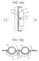
- an indent 14 is formed in the tile on the side that faces water pipes 10.
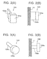
- the shape of support members 15 may be selected based upon manufacturing considerations and the place where they are to be used.
- Figures 2(A) 3(A) and 4(A) show perspective views and Figures 2(B) 3(B) and 4(B) show sectional views of the first through third embodiments.
- support member 15A comprises a T-shaped hook, the tip area 15Aa has a larger sectional shape than the base area 15Ab; with the vertical dimension of tip 15Aa being approximately the same length as the base 15Ab, which is attached to the foregoing water pipes 10.
- the support member has a tip 15Aa that is stepped up from the base 15Ab dimension to improve the ability to be held in place by the foregoing mortar 12, to strongly attach refractory tiles 13 to the foregoing water pipes.
- Figures 5 and 6 show the cross sectional views of fireproof structures for protecting water pipes employing a fourth and fifth embodiment of the support hardware (support members).
Landscapes
- Engineering & Computer Science (AREA)
- Mechanical Engineering (AREA)
- General Engineering & Computer Science (AREA)
- Chemical & Material Sciences (AREA)
- Combustion & Propulsion (AREA)
- Physics & Mathematics (AREA)
- Thermal Sciences (AREA)
- Furnace Housings, Linings, Walls, And Ceilings (AREA)
Abstract
Description
Claims (7)
- A tile installation structure for installing refractory tiles in areas where it would be difficult to slide the refractory tiles along the outside surface of water pipes to engage with support members, said tile installing structure being provided in a fireproof structure for protecting the water pipes installed in boilers and the like in which the refractory tiles are installed upon the support members protruding from the water pipe side with an adhesive such as mortar disposed between the refractory tiles and the support members,
wherein said support members have a sectional dimension at the base which is smaller than a sectional dimension at the tip, and said refractory tiles have an indent on an engagement side facing said support member, said indent is wider than the tip of said support member to allow said indent to be freely inserted in the fore-aft direction onto said support members, to thereby allow the tile installation by pressing said refractory tiles toward the water pipes to engage, with the adhesive such as mortar. - A tile installation structure for installing refractory tiles according to claim 1, wherein said tip of said support member is thicker than said base, being roughly circular in cross section.
- A tile installation structure for installing refractory tiles according to claim 1, wherein said sectional dimension of said support member is stepped up from said base toward said tip.
- A tile installation structure for installing refractory tiles according to claim 1, wherein said sectional dimension of said support member is smoothly tapered to the larger dimension from said base toward said tip.
- A tile installation structure for installing refractory tiles according to claim 1, wherein an opening of said indent on said refractory tiles is wider than the tip of said support member to allow said indent to be freely inserted in the fore-aft direction onto said support members, and said indent widens in the depth direction towards the bottom of said indent.
- A tile installation structure for installing refractory tiles according to claim 1, wherein said indent on said refractory tiles is provided with a through hole that passes through said indent to the opposite side of said tiles.
- A fireproof structure in stoker type incinerators where the gas retention time is 2 seconds or more from the secondary air duct, and the incinerator outlet temperature to an upper limit of the fireproof installation reaches about 900 °C to 1200 °C, said fireproof structure provided with an installation structure for refractory tiles to be installed around air supply ducts that supply combustion air, openings for the insertion of monitoring equipment, openings such as manholes for worker egress, and around clinker chill where the water pipes are bent into complex shapes, said installation structure to be provided on vertical walls and on ceilings, wherein said installing structure comprises:support members having a sectional dimension at the base which is smaller than a sectional dimension at the tip; andrefractory tiles having an indent on an engagement side facing said support member, said indent being wider than the tip of said support member to allow said indent to be freely inserted in the fore-aft direction onto said support members, to thereby allow the tile installation by pressing said refractory tiles toward the water pipes to engage, with the adhesive such as mortar.
Applications Claiming Priority (3)
| Application Number | Priority Date | Filing Date | Title |
|---|---|---|---|
| JP2001343788 | 2001-11-08 | ||
| JP2001343788 | 2001-11-08 | ||
| PCT/JP2002/011558 WO2003040617A1 (en) | 2001-11-08 | 2002-11-06 | Fixing structure of refractory tile for protecting water tube and refractory structure for protecting water tube |
Publications (2)
| Publication Number | Publication Date |
|---|---|
| EP1443269A1 true EP1443269A1 (en) | 2004-08-04 |
| EP1443269A4 EP1443269A4 (en) | 2006-07-05 |
Family
ID=19157409
Family Applications (1)
| Application Number | Title | Priority Date | Filing Date |
|---|---|---|---|
| EP02780008A Withdrawn EP1443269A4 (en) | 2001-11-08 | 2002-11-06 | Fixing structure of refractory tile for protecting water tube and refractory structure for protecting water tube |
Country Status (4)
| Country | Link |
|---|---|
| EP (1) | EP1443269A4 (en) |
| JP (1) | JP3881984B2 (en) |
| TW (1) | TWI306145B (en) |
| WO (1) | WO2003040617A1 (en) |
Cited By (5)
| Publication number | Priority date | Publication date | Assignee | Title |
|---|---|---|---|---|
| DE102004063813A1 (en) * | 2004-12-30 | 2006-07-13 | Saint-Gobain Industriekeramik Düsseldorf Gmbh | Heat protection body for a protection system for a furnace inner wall |
| CN101634455B (en) * | 2008-07-18 | 2013-04-17 | 巴布科克和威尔科克斯能量产生集团公司 | Contoured flat stud and stud arrangement for cyclone slag taps |
| WO2015070953A1 (en) * | 2013-11-12 | 2015-05-21 | Saint Gobain Industriekeramik Rödental Gmbh | Furnace wall arrangement |
| WO2015187007A1 (en) * | 2014-06-06 | 2015-12-10 | Hkh Development B.V. | Refractory tube wall lining for an incinerator |
| US10415828B2 (en) | 2014-06-06 | 2019-09-17 | Hkh Development B.V. | Refractory tube wall lining for an incinerator |
Families Citing this family (5)
| Publication number | Priority date | Publication date | Assignee | Title |
|---|---|---|---|---|
| DE10303173B4 (en) * | 2003-01-27 | 2005-06-30 | Saint-Gobain Industriekeramik Düsseldorf Gmbh | Pipe wall protection for a boiler pipe wall |
| USD761095S1 (en) | 2015-03-06 | 2016-07-12 | Van der Hoeff Refractories B.V. | Bolt |
| JP6221186B2 (en) * | 2015-12-09 | 2017-11-01 | 三菱重工環境・化学エンジニアリング株式会社 | Refractory for water tube protection |
| CN114060837A (en) * | 2021-11-02 | 2022-02-18 | 中国船舶重工集团公司第七0三研究所 | Masonry structure suitable for side wall refractory material of tail flue of marine supercharged boiler |
| JP7752086B2 (en) * | 2022-03-31 | 2025-10-09 | Agcセラミックス株式会社 | Refractory tile, refractory structure, combustion furnace, and refractory tile installation method |
Family Cites Families (8)
| Publication number | Priority date | Publication date | Assignee | Title |
|---|---|---|---|---|
| JPS6011295B2 (en) * | 1981-06-11 | 1985-03-25 | 株式会社 タクマ | Clinker prevention water wall |
| JPS58224224A (en) * | 1982-06-24 | 1983-12-26 | Asahi Glass Co Ltd | Radiation promoter and radiation promoting heater furnace |
| JPH0730883B2 (en) * | 1985-12-27 | 1995-04-10 | 日本ドライブイツト株式会社 | Boiler tube construction or repair method |
| FR2595792B1 (en) * | 1986-03-17 | 1990-02-02 | Mediterranee Const Navales Ind | IMPROVEMENTS IN FIXING PROTECTIVE ELEMENTS OF BOILER COMBUSTION CHAMBERS |
| JPH01106706U (en) * | 1987-12-29 | 1989-07-18 | ||
| US5243801A (en) * | 1992-02-20 | 1993-09-14 | The Babcock & Wilcox Company | Refractory tile for heat exchanger protection |
| EP0962696A4 (en) * | 1997-11-28 | 2002-03-06 | Mitsubishi Heavy Ind Ltd | Water tube protective refractory structure and method of assembling the same |
| TWI226418B (en) * | 2001-11-08 | 2005-01-11 | Mitsubishi Heavy Ind Ltd | Fireproof structure and installation method for protecting water pipes |
-
2002
- 2002-11-06 EP EP02780008A patent/EP1443269A4/en not_active Withdrawn
- 2002-11-06 WO PCT/JP2002/011558 patent/WO2003040617A1/en not_active Ceased
- 2002-11-06 JP JP2003542833A patent/JP3881984B2/en not_active Expired - Lifetime
- 2002-11-08 TW TW91132892A patent/TWI306145B/en not_active IP Right Cessation
Cited By (7)
| Publication number | Priority date | Publication date | Assignee | Title |
|---|---|---|---|---|
| DE102004063813A1 (en) * | 2004-12-30 | 2006-07-13 | Saint-Gobain Industriekeramik Düsseldorf Gmbh | Heat protection body for a protection system for a furnace inner wall |
| CN101634455B (en) * | 2008-07-18 | 2013-04-17 | 巴布科克和威尔科克斯能量产生集团公司 | Contoured flat stud and stud arrangement for cyclone slag taps |
| WO2015070953A1 (en) * | 2013-11-12 | 2015-05-21 | Saint Gobain Industriekeramik Rödental Gmbh | Furnace wall arrangement |
| WO2015187007A1 (en) * | 2014-06-06 | 2015-12-10 | Hkh Development B.V. | Refractory tube wall lining for an incinerator |
| US10415828B2 (en) | 2014-06-06 | 2019-09-17 | Hkh Development B.V. | Refractory tube wall lining for an incinerator |
| EP3627052A1 (en) * | 2014-06-06 | 2020-03-25 | HKH Development B.V. | Combination of a refactory lining and a tube wall for an incinerator |
| EA036228B1 (en) * | 2014-06-06 | 2020-10-15 | Хкх Девелопмент Б.В. | Refractory tube wall lining for an incinerator |
Also Published As
| Publication number | Publication date |
|---|---|
| TWI306145B (en) | 2009-02-11 |
| WO2003040617A1 (en) | 2003-05-15 |
| JP3881984B2 (en) | 2007-02-14 |
| JPWO2003040617A1 (en) | 2005-03-03 |
| TW200303405A (en) | 2003-09-01 |
| EP1443269A4 (en) | 2006-07-05 |
Similar Documents
| Publication | Publication Date | Title |
|---|---|---|
| EP0116233B1 (en) | Fire stop | |
| JP3281630B2 (en) | Refractory structure for protecting water pipes and method of assembling the same | |
| JPWO1999028674A1 (en) | Fireproof structure for protecting water pipes and assembly method thereof | |
| US6837015B2 (en) | Installation method of fireproof structure for protecting water pipes | |
| JP3881984B2 (en) | Mounting structure of fireproof tile for water pipe protection and fireproof structure for water pipe protection | |
| EP1310731B1 (en) | Fireproof structure for protecting water pipes of a heat exchanger and installation method | |
| JPH10503006A (en) | New water cooling wall tube block structure | |
| CN100427867C (en) | Rotary kiln | |
| US20070234939A1 (en) | Refractory body | |
| CA2332668C (en) | Refractory ceramic plate and accompanying wall structure for an incinerator | |
| GB2108614A (en) | Fire-seal for pipe or duct extending through wall, floor or ceiling | |
| JPS5937432B2 (en) | How to protect the metal structure inside a kiln | |
| EP2024683A2 (en) | Refractory tiles for heat exchangers | |
| JP6221186B2 (en) | Refractory for water tube protection | |
| US20090241815A1 (en) | Heat Protection Body for a Protection System for an Interior Wall of a Furnace | |
| US10371447B2 (en) | Refractory anchor assembly | |
| JP3534718B2 (en) | How to assemble a refractory structure for water pipe protection | |
| NL1041195B1 (en) | Refractory lining for a pipe wall of an incinerator. | |
| CN213395901U (en) | Hot-blast furnace and prevent falling brick flame path thereof | |
| JP2007162432A (en) | Tunnel segments and tunnel structures | |
| JPH1025480A (en) | Plug holding structure for coke oven lid | |
| PL63711Y1 (en) | Chimney element | |
| JPH08136157A (en) | Thin wall shaped refractory structure for protection of water-tube wall |
Legal Events
| Date | Code | Title | Description |
|---|---|---|---|
| PUAI | Public reference made under article 153(3) epc to a published international application that has entered the european phase |
Free format text: ORIGINAL CODE: 0009012 |
|
| 17P | Request for examination filed |
Effective date: 20030708 |
|
| AK | Designated contracting states |
Kind code of ref document: A1 Designated state(s): AT BE BG CH CY CZ DE DK EE ES FI FR GB GR IE IT LI LU MC NL PT SE SK TR |
|
| A4 | Supplementary search report drawn up and despatched |
Effective date: 20060608 |
|
| RIC1 | Information provided on ipc code assigned before grant |
Ipc: F23M 5/08 20060101ALI20060601BHEP Ipc: F23M 5/04 20060101ALI20060601BHEP Ipc: F22B 37/10 20060101AFI20030604BHEP |
|
| 17Q | First examination report despatched |
Effective date: 20080605 |
|
| STAA | Information on the status of an ep patent application or granted ep patent |
Free format text: STATUS: THE APPLICATION IS DEEMED TO BE WITHDRAWN |
|
| 18D | Application deemed to be withdrawn |
Effective date: 20081016 |