EP1443218A2 - Precision sensor for a hydraulic cylinder - Google Patents
Precision sensor for a hydraulic cylinder Download PDFInfo
- Publication number
- EP1443218A2 EP1443218A2 EP04009658A EP04009658A EP1443218A2 EP 1443218 A2 EP1443218 A2 EP 1443218A2 EP 04009658 A EP04009658 A EP 04009658A EP 04009658 A EP04009658 A EP 04009658A EP 1443218 A2 EP1443218 A2 EP 1443218A2
- Authority
- EP
- European Patent Office
- Prior art keywords
- transducer
- sensor
- cylinder
- translating member
- rotating element
- Prior art date
- Legal status (The legal status is an assumption and is not a legal conclusion. Google has not performed a legal analysis and makes no representation as to the accuracy of the status listed.)
- Granted
Links
- 238000006073 displacement reaction Methods 0.000 claims abstract description 41
- 238000000034 method Methods 0.000 claims description 12
- 239000012530 fluid Substances 0.000 claims description 11
- 230000005355 Hall effect Effects 0.000 claims description 6
- 230000001939 inductive effect Effects 0.000 claims description 5
- 238000004891 communication Methods 0.000 claims description 2
- 230000006835 compression Effects 0.000 description 4
- 238000007906 compression Methods 0.000 description 4
- 229920000271 Kevlar® Polymers 0.000 description 3
- 238000010276 construction Methods 0.000 description 3
- 238000005516 engineering process Methods 0.000 description 3
- 239000000463 material Substances 0.000 description 3
- 239000004033 plastic Substances 0.000 description 3
- 238000010586 diagram Methods 0.000 description 2
- 239000011521 glass Substances 0.000 description 2
- 229920001778 nylon Polymers 0.000 description 2
- 230000003287 optical effect Effects 0.000 description 2
- 229910000831 Steel Inorganic materials 0.000 description 1
- 239000000853 adhesive Substances 0.000 description 1
- 230000001070 adhesive effect Effects 0.000 description 1
- 230000001010 compromised effect Effects 0.000 description 1
- 230000001143 conditioned effect Effects 0.000 description 1
- 238000009434 installation Methods 0.000 description 1
- 239000013618 particulate matter Substances 0.000 description 1
- 239000010959 steel Substances 0.000 description 1
- XLYOFNOQVPJJNP-UHFFFAOYSA-N water Substances O XLYOFNOQVPJJNP-UHFFFAOYSA-N 0.000 description 1
Images


Classifications
-
- F—MECHANICAL ENGINEERING; LIGHTING; HEATING; WEAPONS; BLASTING
- F15—FLUID-PRESSURE ACTUATORS; HYDRAULICS OR PNEUMATICS IN GENERAL
- F15B—SYSTEMS ACTING BY MEANS OF FLUIDS IN GENERAL; FLUID-PRESSURE ACTUATORS, e.g. SERVOMOTORS; DETAILS OF FLUID-PRESSURE SYSTEMS, NOT OTHERWISE PROVIDED FOR
- F15B15/00—Fluid-actuated devices for displacing a member from one position to another; Gearing associated therewith
- F15B15/20—Other details, e.g. assembly with regulating devices
- F15B15/28—Means for indicating the position, e.g. end of stroke
- F15B15/2815—Position sensing, i.e. means for continuous measurement of position, e.g. LVDT
- F15B15/283—Position sensing, i.e. means for continuous measurement of position, e.g. LVDT using a cable wrapped on a drum and attached to the piston
-
- G—PHYSICS
- G01—MEASURING; TESTING
- G01D—MEASURING NOT SPECIALLY ADAPTED FOR A SPECIFIC VARIABLE; ARRANGEMENTS FOR MEASURING TWO OR MORE VARIABLES NOT COVERED IN A SINGLE OTHER SUBCLASS; TARIFF METERING APPARATUS; MEASURING OR TESTING NOT OTHERWISE PROVIDED FOR
- G01D5/00—Mechanical means for transferring the output of a sensing member; Means for converting the output of a sensing member to another variable where the form or nature of the sensing member does not constrain the means for converting; Transducers not specially adapted for a specific variable
- G01D5/12—Mechanical means for transferring the output of a sensing member; Means for converting the output of a sensing member to another variable where the form or nature of the sensing member does not constrain the means for converting; Transducers not specially adapted for a specific variable using electric or magnetic means
- G01D5/14—Mechanical means for transferring the output of a sensing member; Means for converting the output of a sensing member to another variable where the form or nature of the sensing member does not constrain the means for converting; Transducers not specially adapted for a specific variable using electric or magnetic means influencing the magnitude of a current or voltage
- G01D5/20—Mechanical means for transferring the output of a sensing member; Means for converting the output of a sensing member to another variable where the form or nature of the sensing member does not constrain the means for converting; Transducers not specially adapted for a specific variable using electric or magnetic means influencing the magnitude of a current or voltage by varying inductance, e.g. by a movable armature
- G01D5/22—Mechanical means for transferring the output of a sensing member; Means for converting the output of a sensing member to another variable where the form or nature of the sensing member does not constrain the means for converting; Transducers not specially adapted for a specific variable using electric or magnetic means influencing the magnitude of a current or voltage by varying inductance, e.g. by a movable armature differentially influencing two coils
- G01D5/2291—Linear or rotary variable differential transformers (LVDTs/RVDTs) having a single primary coil and two secondary coils
-
- G—PHYSICS
- G01—MEASURING; TESTING
- G01D—MEASURING NOT SPECIALLY ADAPTED FOR A SPECIFIC VARIABLE; ARRANGEMENTS FOR MEASURING TWO OR MORE VARIABLES NOT COVERED IN A SINGLE OTHER SUBCLASS; TARIFF METERING APPARATUS; MEASURING OR TESTING NOT OTHERWISE PROVIDED FOR
- G01D2205/00—Indexing scheme relating to details of means for transferring or converting the output of a sensing member
- G01D2205/20—Detecting rotary movement
- G01D2205/22—Detecting rotary movement by converting the rotary movement into a linear movement
Definitions
- the invention generally relates to position sensors, and more particularly to linear position sensors for use on power cylinders.
- Equipment implementing hydraulic cylinders for mechanical movement depend upon operators to manually control the moveable elements of the equipment.
- the operator must manually move control levers to open and close hydraulic valves that direct pressurized fluid to hydraulic cylinders. For example, when the operator lifts a lift arm, the operator actually moves a lever associated with the lift arm, causing a valve to release pressurized fluid to the lift arm cylinder.
- the use of levers to control hydraulic equipment depends upon manual dexterity and requires great skill. Improperly operated equipment poses a safety hazard, and operators have been known to damage overhead utility wires, underground wiring, water mains, and underground gas lines through faulty operation of excavators, bucket loaders or like equipment.
- the machine's operating efficiency is also a function of the operator's skill.
- An inexperienced or unskilled operator typically fails to achieve the optimum performance levels of the equipment. For instance, the operator may not consistently apply the force necessary for peak performance due to a concern over striking a hazard. Efficiency is also compromised when the operator fails to drive a cylinder smoothly. The operator alternately overdrives or underdrives the cylinder, resulting in abrupt starts and stops of the moveable element and thereby derating system performance. As a result, the skill level necessary to properly and safely operate heavy equipment is typically imparted through long and costly training courses and apprenticeships.
- these systems and others like them share a common feature in that they implement a position sensor.
- these sensors are rotary potentiometers as, for instance, suggested in Murakmi, Kato and Ota, Precision Angle Sensor Unit for Construction Machinery, SAE Technical Paper Series 972782, 1997. This sensor relies upon a potentiometer which changes a voltage or current in relation to the position of a bucket or boom.
- Other types of sensors rely upon optical, conductive plastic, or metal-in-glass technologies.
- a sensor provides a precision signal utilizing a non-contacting transducer.
- the sensor mounts inside a hydraulic cylinder, away from the harsh environment, and provides a voltage or current signal indicative of the position of the piston.
- the sensor provides a connector, attached between a cylinder piston and a converting element, for sensing the displacement of the piston.
- the converting element converts the cylinder displacement to a proportional displacement of a translating member.
- a precision transducer senses the displacement of the translating member and provides an electrical output signal proportional to the piston movement or to the piston's position.
- a flexible connector such as a cable is attached to the movable element (a piston).
- the converting element comprises a pick-up spool coupled to the other end of the connector and rotatable about an axis.
- the spool is under tension from a recoil mechanism, such as a spring, coupled to the spool.
- a translating member which can be a lead screw, engages threads on the interior of the spool, and translates along an axis when the spool rotates.
- a transducer is disposed to sense a position or motion of the translating member, and provides an output signal proportional to, and therefore indicative of, the position (or motion) of the translating member.
- the transducer can be a linear variable differential transformer (LVDT), which is a non-contacting transducer.
- LVDT linear variable differential transformer
- the spool For use in a hydraulic cylinder, the sensor's operation is like this.
- the converting element is attached to a cylinder end cap.
- the spool feeds out or draws in cable, thereby tracking the piston's linear displacement.
- the spring causes the spool to wind the cable.
- the cylinder force overcomes the spring tension and pulls cable off the spool.
- the spool is in threaded engagement with a lead screw.
- the spool and lead screw convert the rotary motion of the spool to a linear displacement of the lead screw.
- the displacement is proportional to the piston displacement.
- the lead screw is attached to an LVDT core that moves within an LVDT body when the cylinder moves.
- the LVDT delivers an electrical signal at its output, which can be configured as a position signal, rate signal or the like.
- a feedback sensor for a cylinder provides a precision signal indicative of a piston position with relation to a cylinder.
- the sensor is durable, maintains a long life, and is configured for use in harsh environments.
- An exemplary sensor mounts inside a hydraulic cylinder, thereby protecting the sensor, and uses a non-contacting transducer to provide the precision signal.
- a converting element converts the motion of the piston to a proportional motion of a translating member.
- the transducer which can be located remotely from the piston, senses the position of the translating member, and provides an electrical output signal indicating the piston's position. This signal can be conditioned and used in a feedback control system, a user interface, or any system where such a signal is desirable.
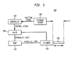
- FIG. 1 a block diagram of an exemplary feedback control system 100 is shown.
- the control system 100 comprises a hydraulic cylinder 104 actuated by a pump 102 and a valve 108.
- the pump 102 delivers hydraulic fluid under pressure to the cylinder 104 which forces the piston 105 to move with respect to the cylinder.
- the valve 108 controls the flow of hydraulic fluid to the cylinder 104.
- a feedback sensor 106 senses the position of the piston 105 and delivers a position signal to a controller 110.
- the controller 110 actuates the valve 108 according to certain instructions.
- the piston 105 may be attached to some other apparatus (not shown) whereby a displacement of the piston causes a displacement of the apparatus.
- a hydraulic cylinder is shown, it should be apparent that other types of cylinders, such as pneumatic cylinders, can be used.
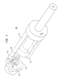
- the hydraulic cylinder 200 comprises a cylinder enclosure 210 and a piston 212.
- the piston 212 is operable to translate in dependence upon hydraulic fluid pumped into the cylinder.
- the cylinder enclosure 210 further includes a base 214, and the piston 212 is a moveable element with respect to the base.
- a precision sensor 218 provides a position related signal across the terminals 219 and 222. For instance, the sensor delivers a signal across the sensor's terminals indicative of the position "d" in FIG. 2.
- a high pressure bulkhead connector (not shown) provides a mechanism for routing the terminals 219 and 222 to the outside of the cylinder enclosure 210.
- the sensor 218 further comprises a flexible connector 216 attached to the piston 212, a converting element 220 attached to the base 214 and a transducer (not shown).
- the connector 216 also attaches to the converting element 220 and directly imparts the displacement of the piston 212 with respect to the base 214 to the converting element 220.
- the converting element 220 converts this displacement to a proportional displacement of a translating member (not shown).
- the transducer located remote from the piston, senses the position or motion of the translating member.
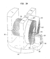
- a first mounting element 302 is provided for attaching the converting element 220 to, for instance, the base of the hydraulic cylinder.
- a second mounting element 306 and a third mounting element 308 are fixedly attached to the first mounting element 302.
- the converting element 220 includes a rotating element 310 rotatably attached between the second mounting element 306 and the third mounting element 308.
- An anti-backlash spring 312 is mounted to the third mounting element 308.
- a block 304 and an anti-rotation spring 305 are attached to the first mounting element 302.
- An arm 320 attaches to a translating member 324 at one end and engages the block 304 at the other.
- a spring 317 for providing a rotary mechanism for the rotating element 310 is housed in a spring housing or spring mounting (not shown). The housing is attached to the first mounting element 302.
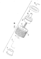
- FIGs. 3B and 3C an exploded view of the converting element 218 is shown.
- a press-in hub 316 having a shaft 309 with internal threads is rotatably attached to a bushing 321.
- the bushing is fixedly attached to the third mounting element 308.
- the third mounting element can comprise an upper half 308A and a lower half 308B.
- the rotating element 310 defines an internal opening into which the hub is pressed so that it rotates as the rotating element 310 rotates.
- a bushing 322 fixedly mounts in the second mounting element 306 which can also comprise an upper half 306A and a lower half 306B.
- the brackets 306 and 308 define a circular opening for attaching the bushings 322 and 321, respectively.
- An axle 323 attaches to the bushing 322, and the rotating element 310 rotatably engages the bushing 322.
- the transducer is a linear variable differential transformer (LVDT), which has a core and a body.
- the LVDT body acts as the axle 323.
- the LVDT body can be internal to a separate axle.
- the LVDT core 325 is attached to the translating member 324 and disposed to translate within the LVDT body.
- the flexible connector 216 attaches to the piston 212 which causes the rotating element 310 to rotate in a first direction when the piston 212 moves away from the cylinder base 214.
- the spring 317 causes the rotating element 310 to rotate in a direction opposite to the rotation caused by the piston moving away from the base 214.
- the flexible connector winds around the rotating element 310 when the piston 212 moves toward the base 214, and unwinds from the rotating element 310 when the piston moves away from the base.
- the linear motion of the piston 212 converts to the angular motion of the rotating element 310 via the pulling action of the piston on the flexible connector and due to the rotational action of the spring 317.
- the hub 316 rotates with it.
- the hub's internal threads engage threads on the translating member 324.
- the thread arrangement is chosen such that the movement of the translating member is proportional to the movement of the piston.
- the threads can be acme, square, modified square, buttress, unified, ISO, ball bearing, extra-fine pitch or any other of various known threads.
- the position of the translating member 324 with respect to the transducer is in a one-to-one correspondence with the position of the piston 212.
- the LVDT 323, 325 senses a position (or a movement) of the translating member and provides a position related signal.
- the precision and performance of the sensor is enhanced by providing the previously set forth anti-rotation elements 320, 304 and 305 and anti-backlash elements 320 and 312.
- the rotating element 310 rotates, causing the translating member 324 to translate along an axis, there is a small frictional force between the inner threads of the hub and the external threads formed on the translating member. This small frictional force is overcome before the translating member moves.
- the arm 320 is provided at an end of the translating member 324.
- the arm 320 bends substantially perpendicular to a longitudinal axis of the translating member and engages the block 304.
- the arm 320 is shown engaging the block in FIG. 3A such that, when the rotating element 310 rotates in a counterclockwise direction, the block inhibits the arm 320 from turning, thereby overcoming any frictional force arising from the threaded engagement.
- the anti-rotation spring 305 applies a force to the arm such that it engages the block 304 at substantially all times.
- the force exerted by this spring is perpendicular to the longitudinal axis of the translating member 324 and is chosen such that it overcomes the frictional force caused by the threaded engagement when, with reference to FIG. 3A, the rotating element 310 rotates in a clockwise direction.
- various other equivalent structures can be used to inhibit the motion of the arm 320 when the rotating element 310 rotates.
- the spring 305 instead of the spring 305, another block can be used.
- the arm 320 can be held between two blocks or a slot formed in one block. In any configuration, the anti-rotational forces upon the arm 320 are such that the arm translates when the rotating element 310 rotates.
- the tolerances of the threads can introduce a dead space between the threads.
- the piston can move some small distance before the threads engage. In other words, depending upon the thread tolerance, there may be play between the threads.
- the spring applies a force to the arm 320 directed along the translating member's longitudinal axis. This force holds the translating member in substantially constant threaded engagement with the internal threads of the hub 316.
- the force exerted by this spring is chosen such that the translating member may move against the spring when the piston displaces to cause such movement.
- the rotating element 310 can be configured to enhance the performance of the sensor by forming grooves thereon so that the flexible connector 216 winds up along successive grooves of the rotating element 310. In this way, no portion of the flexible connector 216 lies over another portion.
- wind guides can be used, or for displacements of large magnitude relative to the storage capacity of the rotating element, the rotating element can be configured such that some portions of the flexible connector overlay other portions of the flexible connector.
- a connector made of Kevlar®, and materials like it, provide desirable attributes, including low stretch, tolerance to a hydraulic fluid environment, and stability over a wide range of temperature (low coefficient of thermal expansion).
- Kevlar® is known to have a coefficient of thermal expansion on the order of -.000002/degree Farenheit (-2 parts per million per degree Farenheit).
- the connector can also comprise other types of cable, such as metallic cable, Nylon®, or stranded cable, and can be coated to provide longer life or to adjust the coefficient of friction. Its diameter can also be adjusted to meet storage needs on the rotating element or to decrease windage.
- the connector can be affixed to the rotating element or moveable element by well-known methods, such as a clevis, pin, weld, bolt or screw, splice, adhesive, threaded terminal, swayed oval, eye, ball and socket, thimble, or a strap fork.
- the transducer is a linear variable differential transformer (LVDT).
- LVDT linear variable differential transformer
- other types of transducers can be implemented without departing from the principles of the invention, including differential variable reluctance transducers (DVRTs®), wire wound potentiometers, conductive plastic potentiometers, inductive or capacitive sensors, Hall-effect transducers, or sensors based upon light emitting diodes, or laser light.
- the target element for the transducer affixes to the translating member.
- the sensing element is disposed to sense the motion or position of the target element.
- the rotational spring can be a spiral torsion spring, a volute spring, a constant force extension spring, a helical torsion spring, a twisted elastic element, a round tension or compression spring, a cantilever tension or compression spring or any other type of spring which may be usable to impart a rotational action on the rotating element.
- the arm 320 can also be a pin or other similar structure for engaging the block 304 and the anti-backlash spring 312.
- an LVDT core 424 is caused to translate along an axis substantially parallel to an axis of rotation for a rotating element 410.
- the flexible connector 420 affixes to the rotating element 410 and to a movable element (not shown).
- a lead screw 415 threadedly engages the rotating element 410 at one end.
- the lead screw is affixed to an arm 422.
- the LVDT core 424 affixes to the other end of the arm 422 and is disposed to translate in an LVDT body 426.
- a recoil mechanism 428 causes the rotating element 410 to wind the connector 420 when the moveable element (not shown) moves such that there is no tension on the connector 420. This also causes the LVDT core 424 to translate within the LVDT body 426. The LVDT thereby provides a position related signal for the movable element (not shown).
- the senor can also be affixed in various locations within a cylinder.
- a sensor 500 is shown attached to the cylinder end cap 503 defining the piston shaft aperture.
- the flexible connector 502 is affixed to the same side of the piston as the shaft. Operation of this configuration is the same with respect to FIGs. 2, 3A, B, and C.
- vanous mechanical connections can be made between the transducer and the converting element of the sensor.
- an actuated cam 602 is shown engaged with an LVDT core 604 and with the sensor's converting element 606.
- a mechanical connection between the converting element 702 and the transducer 704 is made via an extension cable 706.
- the converting element can be configured in various ways without departing from the principles of the invention.
- gears instead of threads can convert the linear displacement of the movable element to the linear displacement of the translating member.
- various pulleys, guides or blocks and tackle can be provided to route the connector from the movable element to the sensor's converting element.
Abstract
Description
- This application claims the benefit of United States Provisional Application Serial No. 60/104866, filed on October 20, 1998.
- The invention generally relates to position sensors, and more particularly to linear position sensors for use on power cylinders.
- Equipment implementing hydraulic cylinders for mechanical movement, such as excavators and other heavy construction equipment, depend upon operators to manually control the moveable elements of the equipment. The operator must manually move control levers to open and close hydraulic valves that direct pressurized fluid to hydraulic cylinders. For example, when the operator lifts a lift arm, the operator actually moves a lever associated with the lift arm, causing a valve to release pressurized fluid to the lift arm cylinder. The use of levers to control hydraulic equipment depends upon manual dexterity and requires great skill. Improperly operated equipment poses a safety hazard, and operators have been known to damage overhead utility wires, underground wiring, water mains, and underground gas lines through faulty operation of excavators, bucket loaders or like equipment.
- In addition to the safety hazards caused by improperly operated equipment, the machine's operating efficiency is also a function of the operator's skill. An inexperienced or unskilled operator typically fails to achieve the optimum performance levels of the equipment. For instance, the operator may not consistently apply the force necessary for peak performance due to a concern over striking a hazard. Efficiency is also compromised when the operator fails to drive a cylinder smoothly. The operator alternately overdrives or underdrives the cylinder, resulting in abrupt starts and stops of the moveable element and thereby derating system performance. As a result, the skill level necessary to properly and safely operate heavy equipment is typically imparted through long and costly training courses and apprenticeships.
- There have been various attempts at implementing an automated control system for use on heavy equipment. One such system is disclosed in U.S. Patent No. 4,288,196. The system described therein provides for a computer programmable system for setting the lowermost point of a backhoe bucket. In U.S. Patent No. 4,945,221, a control system for an excavator is disclosed. The system attempts to control the position of the bucket cutting edge to a desired depth. Another position locating system for heavy equipment is disclosed in U.S. Patent No. 5,404,661.
- These systems and others like them share a common feature in that they implement a position sensor. Typically, these sensors are rotary potentiometers as, for instance, suggested in Murakmi, Kato and Ota, Precision Angle Sensor Unit for Construction Machinery, SAE Technical Paper Series 972782, 1997. This sensor relies upon a potentiometer which changes a voltage or current in relation to the position of a bucket or boom. Other types of sensors rely upon optical, conductive plastic, or metal-in-glass technologies.
- It is a disadvantage of these sensors that they mount to the outside of the machinery, thereby exposing them to the environment. In the case of heavy equipment, this environment includes severe temperatures, excessive moisture, and air-borne particulate matter which may infect the sensor. In the case of optical, conductive plastic and metal-in-glass technologies, the sensors would rapidly degrade if used on construction equipment. Furthermore, some of these sensors use contacting components that are susceptible to wear, vibration and temperature. As a result, no sensor mountable to the outside of heavy equipment or relying upon contacting elements has gained widespread use in the industry.
- There have been attempts to overcome the limitations of contacting sensors by using electromagnetic energy. For example, the system disclosed in U.S. Patent No. 4,945,221 discloses using lasers for sensing position. Others suggest using RF energy or the like to provide a feedback signal. These systems, however, have not replaced the less expensive potentiometers due to their complexity of use and their expense.
- As the demands placed upon actuated machinery increases, so does the demand for a low cost, long-life sensor operable in a harsh environment. Despite the development of highly sophisticated control systems, computer processors and application specific software, the implementation of this technology in electrohydraulic equipment has been curtailed by the failure to provide a long-life, cost-effective precision sensor operable in harsh environments.
- A sensor according to the principles of the invention provides a precision signal utilizing a non-contacting transducer. In an exemplary embodiment, the sensor mounts inside a hydraulic cylinder, away from the harsh environment, and provides a voltage or current signal indicative of the position of the piston. The sensor provides a connector, attached between a cylinder piston and a converting element, for sensing the displacement of the piston. The converting element converts the cylinder displacement to a proportional displacement of a translating member. A precision transducer senses the displacement of the translating member and provides an electrical output signal proportional to the piston movement or to the piston's position.
- In one exemplary sensor according to the principles of the invention, a flexible connector such as a cable is attached to the movable element (a piston). The converting element comprises a pick-up spool coupled to the other end of the connector and rotatable about an axis. The spool is under tension from a recoil mechanism, such as a spring, coupled to the spool. A translating member, which can be a lead screw, engages threads on the interior of the spool, and translates along an axis when the spool rotates. A transducer is disposed to sense a position or motion of the translating member, and provides an output signal proportional to, and therefore indicative of, the position (or motion) of the translating member. The transducer can be a linear variable differential transformer (LVDT), which is a non-contacting transducer. Of course, other transducers, including those using contacting components, can be used.
- For use in a hydraulic cylinder, the sensor's operation is like this. The converting element is attached to a cylinder end cap. As the cylinder piston moves within the cylinder, the spool feeds out or draws in cable, thereby tracking the piston's linear displacement. As the cylinder moves toward the spool, the spring causes the spool to wind the cable. When the cylinder moves away from the spool, the cylinder force overcomes the spring tension and pulls cable off the spool. The spool is in threaded engagement with a lead screw. As the spool rotates, the spool and lead screw convert the rotary motion of the spool to a linear displacement of the lead screw. The displacement is proportional to the piston displacement. The lead screw is attached to an LVDT core that moves within an LVDT body when the cylinder moves. The LVDT delivers an electrical signal at its output, which can be configured as a position signal, rate signal or the like.
- A more complete understanding of the invention may be obtained from consideration of the following description in conjunction with the drawings in which:
- FIG. 1 is a block diagram of an exemplary feedback control system for a hydraulic cylinder;
- FIG. 2 shows a perspective of an exemplary cylinder according to the principles of the invention;
- FIGs. 3A, B and C show an exemplary sensor according to the principles of the invention;
- FIG. 4 shows another exemplary sensor according to the principles of the invention;
- FIG. 5 shows another exemplary sensor according to the principles of the invention;
- FIG. 6 shows another exemplary sensor according to the principles of the invention; and,
- FIG. 7 shows another exemplary sensor according to the principles of the invention.
-
- A feedback sensor for a cylinder according to the principles of the invention provides a precision signal indicative of a piston position with relation to a cylinder. The sensor is durable, maintains a long life, and is configured for use in harsh environments. An exemplary sensor mounts inside a hydraulic cylinder, thereby protecting the sensor, and uses a non-contacting transducer to provide the precision signal. A converting element converts the motion of the piston to a proportional motion of a translating member. The transducer, which can be located remotely from the piston, senses the position of the translating member, and provides an electrical output signal indicating the piston's position. This signal can be conditioned and used in a feedback control system, a user interface, or any system where such a signal is desirable.
- In FIG. 1, a block diagram of an exemplary
feedback control system 100 is shown. Thecontrol system 100 comprises ahydraulic cylinder 104 actuated by apump 102 and avalve 108. As is known in the art, thepump 102 delivers hydraulic fluid under pressure to thecylinder 104 which forces thepiston 105 to move with respect to the cylinder. Thevalve 108 controls the flow of hydraulic fluid to thecylinder 104. To implement feedback control, afeedback sensor 106 senses the position of thepiston 105 and delivers a position signal to acontroller 110. Thecontroller 110 actuates thevalve 108 according to certain instructions. Thepiston 105 may be attached to some other apparatus (not shown) whereby a displacement of the piston causes a displacement of the apparatus. Although a hydraulic cylinder is shown, it should be apparent that other types of cylinders, such as pneumatic cylinders, can be used. - Referring to FIG. 2, a
hydraulic cylinder 200 that can be used in thefeedback control system 100 of FIG. 1 is shown. Thehydraulic cylinder 200 comprises acylinder enclosure 210 and apiston 212. Thepiston 212 is operable to translate in dependence upon hydraulic fluid pumped into the cylinder. Thecylinder enclosure 210 further includes abase 214, and thepiston 212 is a moveable element with respect to the base. Aprecision sensor 218 provides a position related signal across theterminals terminals cylinder enclosure 210. Thesensor 218 further comprises aflexible connector 216 attached to thepiston 212, a convertingelement 220 attached to thebase 214 and a transducer (not shown). Theconnector 216 also attaches to the convertingelement 220 and directly imparts the displacement of thepiston 212 with respect to the base 214 to the convertingelement 220. The convertingelement 220 converts this displacement to a proportional displacement of a translating member (not shown). The transducer, located remote from the piston, senses the position or motion of the translating member. - An exemplary embodiment of the converting
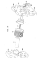
element 220 is described with reference to FIGS. 3A, 3B and 3C. A first mountingelement 302 is provided for attaching the convertingelement 220 to, for instance, the base of the hydraulic cylinder. Asecond mounting element 306 and athird mounting element 308 are fixedly attached to the first mountingelement 302. The convertingelement 220 includes arotating element 310 rotatably attached between the second mountingelement 306 and the third mountingelement 308. Ananti-backlash spring 312 is mounted to the third mountingelement 308. Ablock 304 and ananti-rotation spring 305 are attached to the first mountingelement 302. Anarm 320 attaches to a translatingmember 324 at one end and engages theblock 304 at the other. Aspring 317 for providing a rotary mechanism for therotating element 310 is housed in a spring housing or spring mounting (not shown). The housing is attached to the first mountingelement 302. - In FIGs. 3B and 3C an exploded view of the converting
element 218 is shown. A press-inhub 316 having ashaft 309 with internal threads is rotatably attached to abushing 321. The bushing is fixedly attached to the third mountingelement 308. For ease of installation, the third mounting element can comprise anupper half 308A and a lower half 308B. The translatingmember 324, having threads formed thereon, engages the internal threads of thehub 316. Therotating element 310 defines an internal opening into which the hub is pressed so that it rotates as therotating element 310 rotates. On a side opposite thehub 316, abushing 322 fixedly mounts in the second mountingelement 306 which can also comprise anupper half 306A and alower half 306B. As shown in FIG. 3C, thebrackets bushings axle 323 attaches to thebushing 322, and therotating element 310 rotatably engages thebushing 322. In this exemplary embodiment, the transducer is a linear variable differential transformer (LVDT), which has a core and a body. The LVDT body acts as theaxle 323. Alternatively, the LVDT body can be internal to a separate axle. TheLVDT core 325 is attached to the translatingmember 324 and disposed to translate within the LVDT body. - Operation of this exemplary sensor is explained with reference to FIGs. 2, 3A, 3B and 3C. The
flexible connector 216 attaches to thepiston 212 which causes therotating element 310 to rotate in a first direction when thepiston 212 moves away from thecylinder base 214. When the piston travels toward thecylinder base 214, thespring 317 causes therotating element 310 to rotate in a direction opposite to the rotation caused by the piston moving away from thebase 214. In other words, the flexible connector winds around therotating element 310 when thepiston 212 moves toward thebase 214, and unwinds from therotating element 310 when the piston moves away from the base. The linear motion of thepiston 212 converts to the angular motion of therotating element 310 via the pulling action of the piston on the flexible connector and due to the rotational action of thespring 317. - As the
rotating element 310 rotates, thehub 316 rotates with it. The hub's internal threads engage threads on the translatingmember 324. As the rotating element and hub rotate, the threaded engagement causes the translatingmember 324 to move linearly along the rotational axis of therotating element 310. The thread arrangement is chosen such that the movement of the translating member is proportional to the movement of the piston. The threads can be acme, square, modified square, buttress, unified, ISO, ball bearing, extra-fine pitch or any other of various known threads. Likewise, the position of the translatingmember 324 with respect to the transducer is in a one-to-one correspondence with the position of thepiston 212. TheLVDT - The precision and performance of the sensor is enhanced by providing the previously set forth
anti-rotation elements anti-backlash elements rotating element 310 rotates, causing the translatingmember 324 to translate along an axis, there is a small frictional force between the inner threads of the hub and the external threads formed on the translating member. This small frictional force is overcome before the translating member moves. To overcome this force, thearm 320 is provided at an end of the translatingmember 324. Thearm 320 bends substantially perpendicular to a longitudinal axis of the translating member and engages theblock 304. For purposes of illustration, thearm 320 is shown engaging the block in FIG. 3A such that, when therotating element 310 rotates in a counterclockwise direction, the block inhibits thearm 320 from turning, thereby overcoming any frictional force arising from the threaded engagement. - The
anti-rotation spring 305 applies a force to the arm such that it engages theblock 304 at substantially all times. The force exerted by this spring is perpendicular to the longitudinal axis of the translatingmember 324 and is chosen such that it overcomes the frictional force caused by the threaded engagement when, with reference to FIG. 3A, therotating element 310 rotates in a clockwise direction. It should be apparent that various other equivalent structures can be used to inhibit the motion of thearm 320 when therotating element 310 rotates. For instance, instead of thespring 305, another block can be used. Thus, thearm 320 can be held between two blocks or a slot formed in one block. In any configuration, the anti-rotational forces upon thearm 320 are such that the arm translates when therotating element 310 rotates. - In addition to the frictional force inherent in the threaded engagement, the tolerances of the threads can introduce a dead space between the threads. For example, when the translating
member 324 changes direction, due to a change in the direction of motion of thepiston 212, the piston can move some small distance before the threads engage. In other words, depending upon the thread tolerance, there may be play between the threads. This is overcome by theanti-backlash spring 312 attached to thebracket 308. The spring applies a force to thearm 320 directed along the translating member's longitudinal axis. This force holds the translating member in substantially constant threaded engagement with the internal threads of thehub 316. The force exerted by this spring is chosen such that the translating member may move against the spring when the piston displaces to cause such movement. - It should be apparent that various materials and configurations can be used to implement a sensor according to the principles of the invention. For instance, the
rotating element 310 can be configured to enhance the performance of the sensor by forming grooves thereon so that theflexible connector 216 winds up along successive grooves of therotating element 310. In this way, no portion of theflexible connector 216 lies over another portion. Alternatively, wind guides can be used, or for displacements of large magnitude relative to the storage capacity of the rotating element, the rotating element can be configured such that some portions of the flexible connector overlay other portions of the flexible connector. - Likewise, various materials can be used for the flexible connector. A connector made of Kevlar®, and materials like it, provide desirable attributes, including low stretch, tolerance to a hydraulic fluid environment, and stability over a wide range of temperature (low coefficient of thermal expansion). For example, Kevlar® is known to have a coefficient of thermal expansion on the order of -.000002/degree Farenheit (-2 parts per million per degree Farenheit). The connector can also comprise other types of cable, such as metallic cable, Nylon®, or stranded cable, and can be coated to provide longer life or to adjust the coefficient of friction. Its diameter can also be adjusted to meet storage needs on the rotating element or to decrease windage. Similarly, the connector can be affixed to the rotating element or moveable element by well-known methods, such as a clevis, pin, weld, bolt or screw, splice, adhesive, threaded terminal, swayed oval, eye, ball and socket, thimble, or a strap fork.
- In the embodiment shown in FIGs. 2, 3A, 3B and 3C, the transducer is a linear variable differential transformer (LVDT). It should be apparent to those skilled in the art that other types of transducers can be implemented without departing from the principles of the invention, including differential variable reluctance transducers (DVRTs®), wire wound potentiometers, conductive plastic potentiometers, inductive or capacitive sensors, Hall-effect transducers, or sensors based upon light emitting diodes, or laser light. In each case, the target element for the transducer affixes to the translating member. The sensing element is disposed to sense the motion or position of the target element. Similarly, the rotational spring can be a spiral torsion spring, a volute spring, a constant force extension spring, a helical torsion spring, a twisted elastic element, a round tension or compression spring, a cantilever tension or compression spring or any other type of spring which may be usable to impart a rotational action on the rotating element. Likewise, the
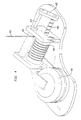
arm 320 can also be a pin or other similar structure for engaging theblock 304 and theanti-backlash spring 312. - Another exemplary embodiment of a sensor according to the principles of the invention is shown in FIG. 4. In this embodiment, an
LVDT core 424 is caused to translate along an axis substantially parallel to an axis of rotation for arotating element 410. Theflexible connector 420 affixes to therotating element 410 and to a movable element (not shown). Alead screw 415 threadedly engages therotating element 410 at one end. At another end, the lead screw is affixed to an arm 422. TheLVDT core 424 affixes to the other end of the arm 422 and is disposed to translate in anLVDT body 426. When the flexible connector is pulled such that it unwinds from therotating element 410, the threaded engagement causes thelead screw 415 to translate. This, in turn, causes theLVDT core 424 to translate within theLVDT body 426. Arecoil mechanism 428 causes therotating element 410 to wind theconnector 420 when the moveable element (not shown) moves such that there is no tension on theconnector 420. This also causes theLVDT core 424 to translate within theLVDT body 426. The LVDT thereby provides a position related signal for the movable element (not shown). - Of course, the sensor can also be affixed in various locations within a cylinder. For instance in FIG. 5, a
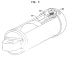
sensor 500 is shown attached to thecylinder end cap 503 defining the piston shaft aperture. Theflexible connector 502 is affixed to the same side of the piston as the shaft. Operation of this configuration is the same with respect to FIGs. 2, 3A, B, and C. - It should also be apparent that vanous mechanical connections can be made between the transducer and the converting element of the sensor. In FIG. 6, an actuated
cam 602 is shown engaged with anLVDT core 604 and with the sensor's convertingelement 606. In FIG. 7, a mechanical connection between the convertingelement 702 and thetransducer 704 is made via anextension cable 706. - Likewise, the converting element can be configured in various ways without departing from the principles of the invention. For instance, gears instead of threads can convert the linear displacement of the movable element to the linear displacement of the translating member. It should also be apparent that for applications with relatively large displacements of the movable element or where an obstruction is located between the converting element and the movable element, various pulleys, guides or blocks and tackle can be provided to route the connector from the movable element to the sensor's converting element.
- It is to be understood that the invention is not limited to the illustrated and described forms of the invention contained herein. It will be apparent to those skilled in the art that various changes may be made without departing from the scope of the invention and the invention is not considered limited to what is shown in the drawings and described in the specification.
- 1. A sensor for providing a position related signal for a first element in
relation to a second element, the sensor comprising:
- a flexible connector having a first end attached to the first element;
- a rotating element attached to the second element and coupled to a second end of said flexible connector;
- a translating member in dependence with said rotating element, wherein a displacement of the first element causes a displacement of said translating member; and,
- a transducer disposed to sense a position of said translating member, wherein said transducer provides the position related signal.
- 2. The sensor of clause 1 further comprising a recoil mechanism coupled to said rotating element for imparting a rotational action on said rotating element.
- 3. The sensor of clause1 wherein said rotating element is a spool having an outer periphery with grooves defined thereon.
- 4. The sensor of clause 1 wherein said translating member is in threaded communication with said rotating element.
- 5. The sensor of clause 1 wherein said translating member displaces along an axis of rotation of said rotating element.
- 6. The sensor of clause 1 wherein said transducer is one selected from the group comprising a LVDT, a DVRT®, a potentiometer, an inductive transducer, a capacitive transducer, a Hall-effect transducer, an LED transducer, and a laser based transducer.
- 7. The sensor of clause 4 further including a mounting element attached in fixed relation to the second element, said rotating element rotatably attached to said mounting element.
- 8. The sensor of clause1 further including an anti-rotational force exerted on said translating member.
- 9. The sensor of clause7 further including:
- a block attached to said mounting element, said translating member having an arm extending substantially perpendicular to a longitudinal axis of said translating member; and,
- an anti-rotational spring attached to said mounting element and engaged with said arm, wherein said anti-rotational spring exerts an anti-rotational force on said arm.
- 10. The sensor of clause 9 further including an anti-backlash spring attached to said mounting element and disposed to exert an anti-backlash force along said longitudinal axis of said translating member.
- 11. The sensor of clause 1 wherein the first element is a piston and said second element is a cylinder, said piston disposed to translate in said cylinder.
- 12. The sensor of clause12 wherein the sensor is located within the cylinder.
- 13. The sensor of clause 11 further comprising hydraulic fluid contained within said cylinder.
- 14. The sensor of clause 1 wherein said rotating element is a spool having an outer periphery with wind guides.
- 15. The sensor of clause 1 further including an anti-backlash force exerted along a longitudinal axis of said translating member.
- 16. The sensor of clause 2 wherein said spring is one selected from the group comprising a spiral torsion spring, a volute spring, a constant force extension spring, an helical torsion spring, a twisted elastic element spring, a round tension spring, a round compression spring, a cantilever tension spring and a cantilever compression spring.
- 17. The sensor of clause 1 wherein said flexible connector is one selected from the group comprising a Kevlar® cable, a steel cable, a Nylon® cable, a stranded cable, and a cable having a thermal coefficient of expansion with a magnitude of less than approximately 15 parts per million per Farenheit degree.
- 18. A device comprising a cylinder for actuating a moveable element and a
sensor for providing a position related signal for the moveable element, the sensor
including:
- a flexible connector having a first end attached to a first element, said first element being in moveable dependence with the moveable element;
- a rotating element attached to a second element and coupled to a second end of said flexible connector;
- a translating member in dependence with said rotating element, wherein a displacement of said first element causes a displacement of said translating member; and,
- a transducer disposed to sense a position of said translating member, wherein said transducer provides the position related signal.
- 19. A piece of heavy equipment having a feedback control system for an
actuated cylinder having a moveable element, comprising a feedback sensor operable to
provide a signal indicative of a position of the moveable element, said feedback sensor
including:
- a connector attached to the moveable element;
- a translating member;
- a converting element attached to said translating member and to said connector, said converting element operable to convert a linear displacement of the moveable element to a linear displacement of said translating member; and,
- a transducer disposed to sense a position of said translating member, wherein said transducer provides the signal.
- 20. The system of clause 19 wherein said actuated cylinder is one selected from the group of a hydraulic cylinder and a pneumatic cylinder.
- 21. The system of clause 19 wherein said actuated cylinder is a hydraulic cylinder and said transducer is operable in a hydraulic fluid.
- 22. A method for sensing a position of a first element moveable within a
cylinder, the steps comprising:
- converting a linear displacement of the first element to a proportional linear displacement of a second element;
- disposing a transducer within said cylinder; and,
- sensing a position of said second element with said transducer.
- 23. The method of clause 22 wherein said converting step includes the steps
of:
- converting said linear displacement of the first element to an angular displacement of a rotatable element; and,
- converting said angular displacement of said rotatable element to a linear displacement of said second element.
- 24. The method of clause 22 wherein said transducer is one selected from the group comprising a LVDT, a DVRT®, a potentiometer, an inductive transducer, a capacitive transducer, a Hall-effect transducer, an LED based transducer, and a laser based transducer.
- 25. The method of clause 22 wherein said transducer is operable to provide a position related signal.
- 26. The method of clause 22 further comprising the step of disposing hydraulic fluid within said cylinder.
-
Claims (23)
- A sensor (218) for providing a position-related signal for a first element (212) in relation to a second element (214), the sensor comprising:characterised in that the sensor further comprises a translating member (324) cooperating with the rotating element (220, 310); anda flexible connector (216) having a first end attachable to the first element (212);a rotating element (220, 310) attachable to the second element (214) and coupled to a second end of the flexible connector (216); anda transducer (323, 704),
in that the transducer (323, 704) is disposed to sense a position of the translating member (324), wherein the transducer (323, 704) provides the position-related signal. - The sensor (218) of claim 1 further comprising a recoil mechanism (428) coupled to said rotating element (220, 310) for imparting a rotational action on said rotating element (220, 310).
- The sensor (218) of claim 1 or 2 wherein the rotating element (220) defines an internal opening.
- The sensor (218) of any one of the preceding claims wherein said translating member (324) is in threaded communication with said rotating element (220, 310).
- The sensor (218) of any one of the preceding claims wherein said translating member (324) displaces along an axis of rotation of said rotating element (220, 310).
- The sensor (218) of any one of the preceding claims wherein said transducer (323, 704) is one selected from the group comprising a LVDT, a DVRT®, a potentiometer, an inductive transducer, a capacitive transducer, a Hall-effect transducer, an LED transducer, and a laser based transducer.
- The sensor (218) of claim 4 further including a mounting element (302) attached in fixed relation to the second element (214), said rotating element (220, 310) rotatably attached to said mounting element (302)
- The sensor (218) of any one of the preceding claims further including an anti-rotational force exerted on said translating member (324).
- The sensor of any one of the preceding claims wherein the translating member (324) linearly displaces upon rotation of the rotating element (220, 310).
- The sensor (218) of any one of the preceding claims wherein the first element (212) is a piston and said second element (214) is a cylinder, said piston disposed to translate in said cylinder.
- The sensor (218) of claim 10 wherein the sensor (218) is located within the cylinder.
- The sensor (218) of claim 10 or 11 further comprising hydraulic fluid contained within said cylinder.
- The sensor (218) of any one of the preceding claims further including an anti-backlash force exerted along a longitudinal axis of said translating member (324).
- A piece of heavy equipment comprising a sensor according to claim 12.
- A method for sensing a position of a first element (212) moveable within a cylinder (200), the steps comprising:characterised in that:in a converting element (220) in fixed relation to the cylinder (200), converting a linear displacement of the first element (212) to a proportional linear displacement of a second element (324), and providing a transducer,the linear displacement of the first element (212) is converted to the proportional linear displacement of the second element (324) via a flexible connector (216) connected to the first element (212) and to the converting element (220);the transducer (323, 325, 704) is disposed within the cylinder (200); andthe method further comprises the step of sensing the linear displacement of the second element (324) with the transducer (323, 325, 704).
- The method of claim 15 wherein said converting step includes the steps of:converting said linear displacement of the first element (212) to an angular displacement of a rotatable element (310), and,converting said angular displacement of said rotatable element (310) to a linear displacement of said second element (324).
- The method of claim 15 or 16 wherein said transducer (323, 325, 704) is one selected from the group comprising a LVDT, a DVRT®, a potentiometer, an inductive transducer, a capacitive transducer, a Hall-effect transducer, an LED based transducer, and a laser based transducer.
- The method of any one of claims 15 to 17 wherein said transducer (323, 325, 704) is operable to provide a position related signal.
- The method of any one of claims 15 to 18 further comprising disposing hydraulic fluid within said cylinder (200).
- The sensor of claim 6 wherein the transducer comprises an LVDT.
- The sensor of claim 6 wherein the transducer comprises a Hall-effect transducer.
- The sensor of claim 3, the transducer being at least partially disposed within the internal opening.
- A sensor for providing a position related signal for a first element in relation to a second element, the sensor comprising:a flexible connector having a first end attached to the first element;a rotating element attached to the second element and coupled to a second end of said flexible connector;a translating member in dependence with said rotating element, wherein a displacement of the first element causes a displacement of said translating member; and,a transducer disposed to sense a position of said translating member, wherein said transducer provides the position related signal
Applications Claiming Priority (5)
| Application Number | Priority Date | Filing Date | Title |
|---|---|---|---|
| US10488698P | 1998-10-20 | 1998-10-20 | |
| US104886P | 1998-10-20 | ||
| US09/302,701 US6234061B1 (en) | 1998-10-20 | 1999-04-30 | Precision sensor for a hydraulic cylinder |
| US302701 | 1999-04-30 | ||
| EP99970715A EP1123464B1 (en) | 1998-10-20 | 1999-10-18 | Precision sensor for a hydraulic cylinder |
Related Parent Applications (1)
| Application Number | Title | Priority Date | Filing Date |
|---|---|---|---|
| EP99970715A Division EP1123464B1 (en) | 1998-10-20 | 1999-10-18 | Precision sensor for a hydraulic cylinder |
Publications (4)
| Publication Number | Publication Date |
|---|---|
| EP1443218A2 true EP1443218A2 (en) | 2004-08-04 |
| EP1443218A9 EP1443218A9 (en) | 2004-10-27 |
| EP1443218A3 EP1443218A3 (en) | 2004-11-17 |
| EP1443218B1 EP1443218B1 (en) | 2007-01-03 |
Family
ID=32659718
Family Applications (1)
| Application Number | Title | Priority Date | Filing Date |
|---|---|---|---|
| EP04009658A Expired - Lifetime EP1443218B1 (en) | 1998-10-20 | 1999-10-18 | Precision sensor for a hydraulic cylinder |
Country Status (1)
| Country | Link |
|---|---|
| EP (1) | EP1443218B1 (en) |
Citations (3)
| Publication number | Priority date | Publication date | Assignee | Title |
|---|---|---|---|---|
| US4288196A (en) | 1979-06-14 | 1981-09-08 | Sutton Ii James O | Computer controlled backhoe |
| US4945221A (en) | 1987-04-24 | 1990-07-31 | Laser Alignment, Inc. | Apparatus and method for controlling a hydraulic excavator |
| US5404661A (en) | 1994-05-10 | 1995-04-11 | Caterpillar Inc. | Method and apparatus for determining the location of a work implement |
Family Cites Families (5)
| Publication number | Priority date | Publication date | Assignee | Title |
|---|---|---|---|---|
| DE2635614A1 (en) * | 1976-08-07 | 1978-02-09 | Georg Rudolf Sillner | Control potentiometer with external setting - has spiral groove in which contact driven by pressure element moves to change setting |
| US4121504A (en) * | 1977-01-21 | 1978-10-24 | Inovec, Inc. | Cylinder positioning systems |
| US4841246A (en) * | 1987-12-29 | 1989-06-20 | Eaton Corporation | Multiturn shaft position sensor having magnet movable with nonrotating linear moving nut |
| DE3835782A1 (en) * | 1988-10-20 | 1990-04-26 | Rexroth Mannesmann Gmbh | Device for measuring angles of rotation |
| FR2674294B1 (en) * | 1991-03-22 | 1993-12-17 | Etudes Montages | HYDRAULIC CYLINDER WITH MOVABLE ROD POSITIONING. |
-
1999
- 1999-10-18 EP EP04009658A patent/EP1443218B1/en not_active Expired - Lifetime
Patent Citations (3)
| Publication number | Priority date | Publication date | Assignee | Title |
|---|---|---|---|---|
| US4288196A (en) | 1979-06-14 | 1981-09-08 | Sutton Ii James O | Computer controlled backhoe |
| US4945221A (en) | 1987-04-24 | 1990-07-31 | Laser Alignment, Inc. | Apparatus and method for controlling a hydraulic excavator |
| US5404661A (en) | 1994-05-10 | 1995-04-11 | Caterpillar Inc. | Method and apparatus for determining the location of a work implement |
Non-Patent Citations (1)
| Title |
|---|
| suggested in Murakmi, Kato and Ota, Precision Angle Sensor Unit for Construction Machinery, SAE Technical Paper Series 972782, 1997. |
Also Published As
| Publication number | Publication date |
|---|---|
| EP1443218A9 (en) | 2004-10-27 |
| EP1443218B1 (en) | 2007-01-03 |
| EP1443218A3 (en) | 2004-11-17 |
Similar Documents
| Publication | Publication Date | Title |
|---|---|---|
| EP1123464B1 (en) | Precision sensor for a hydraulic cylinder | |
| US6694861B2 (en) | Precision sensor for a hydraulic cylinder | |
| US7290476B1 (en) | Precision sensor for a hydraulic cylinder | |
| US8827046B2 (en) | Brake wear measurement system | |
| KR101557084B1 (en) | Improvements to valve actuators | |
| US5270625A (en) | Pneumatic/electric actuator | |
| CA1173530A (en) | Power cylinder with internally mounted position indicator | |
| US3541877A (en) | Single lever control for coordinating multiple motion transmitting devices | |
| CN100358685C (en) | Pipeline processing structure of an industrial robot | |
| CN101567601A (en) | Actuating device with controllable stroke | |
| JPH01226697A (en) | Operating reaction force controller for winch | |
| EP1443218B1 (en) | Precision sensor for a hydraulic cylinder | |
| CN110842968A (en) | Antagonistic driving device adopting capstan and tendon transmission | |
| CN201396328Y (en) | Hydraulic valve control device | |
| KR100311836B1 (en) | Actuating System for Accelerator | |
| CN208138053U (en) | The actuator assembly of diesel engine smart electronics speed-regulating system | |
| CA1299899C (en) | Rotary/linear actuator | |
| CN209231808U (en) | A kind of swing arm electronic hand throttle | |
| US3878738A (en) | Actuator for a transmission modulator valve | |
| CN1593778A (en) | Multi-angle positioning and swinging spray nozzle set used for eruptive fountain | |
| US20190366534A1 (en) | Robotic Arm Assembly | |
| CN110701215B (en) | Electric control electric rotor wing braking system | |
| KR102284710B1 (en) | Linear actuator | |
| EP1924521B1 (en) | Handle for controlling a lifting device | |
| CN211291262U (en) | Mechanical-electrical integrated pull rope sensor of hydraulic actuating mechanism |
Legal Events
| Date | Code | Title | Description |
|---|---|---|---|
| PUAI | Public reference made under article 153(3) epc to a published international application that has entered the european phase |
Free format text: ORIGINAL CODE: 0009012 |
|
| 17P | Request for examination filed |
Effective date: 20040524 |
|
| AC | Divisional application: reference to earlier application |
Ref document number: 1123464 Country of ref document: EP Kind code of ref document: P |
|
| AK | Designated contracting states |
Kind code of ref document: A2 Designated state(s): AT BE CH CY DE DK ES FI FR GB GR IE IT LI LU MC NL PT SE |
|
| PUAL | Search report despatched |
Free format text: ORIGINAL CODE: 0009013 |
|
| AK | Designated contracting states |
Kind code of ref document: A3 Designated state(s): AT BE CH CY DE DK ES FI FR GB GR IE IT LI LU MC NL PT SE |
|
| RIC1 | Information provided on ipc code assigned before grant |
Ipc: 7G 05D 5/02 B Ipc: 7F 15B 15/28 A |
|
| AKX | Designation fees paid |
Designated state(s): AT BE CH CY DE DK ES FI FR GB GR IE IT LI LU MC NL PT SE |
|
| GRAP | Despatch of communication of intention to grant a patent |
Free format text: ORIGINAL CODE: EPIDOSNIGR1 |
|
| GRAS | Grant fee paid |
Free format text: ORIGINAL CODE: EPIDOSNIGR3 |
|
| GRAA | (expected) grant |
Free format text: ORIGINAL CODE: 0009210 |
|
| AC | Divisional application: reference to earlier application |
Ref document number: 1123464 Country of ref document: EP Kind code of ref document: P |
|
| AK | Designated contracting states |
Kind code of ref document: B1 Designated state(s): AT BE CH CY DE DK ES FI FR GB GR IE IT LI LU MC NL PT SE |
|
| PG25 | Lapsed in a contracting state [announced via postgrant information from national office to epo] |
Ref country code: DK Free format text: LAPSE BECAUSE OF FAILURE TO SUBMIT A TRANSLATION OF THE DESCRIPTION OR TO PAY THE FEE WITHIN THE PRESCRIBED TIME-LIMIT Effective date: 20070103 Ref country code: AT Free format text: LAPSE BECAUSE OF FAILURE TO SUBMIT A TRANSLATION OF THE DESCRIPTION OR TO PAY THE FEE WITHIN THE PRESCRIBED TIME-LIMIT Effective date: 20070103 Ref country code: FI Free format text: LAPSE BECAUSE OF FAILURE TO SUBMIT A TRANSLATION OF THE DESCRIPTION OR TO PAY THE FEE WITHIN THE PRESCRIBED TIME-LIMIT Effective date: 20070103 Ref country code: NL Free format text: LAPSE BECAUSE OF FAILURE TO SUBMIT A TRANSLATION OF THE DESCRIPTION OR TO PAY THE FEE WITHIN THE PRESCRIBED TIME-LIMIT Effective date: 20070103 Ref country code: LI Free format text: LAPSE BECAUSE OF FAILURE TO SUBMIT A TRANSLATION OF THE DESCRIPTION OR TO PAY THE FEE WITHIN THE PRESCRIBED TIME-LIMIT Effective date: 20070103 Ref country code: CH Free format text: LAPSE BECAUSE OF FAILURE TO SUBMIT A TRANSLATION OF THE DESCRIPTION OR TO PAY THE FEE WITHIN THE PRESCRIBED TIME-LIMIT Effective date: 20070103 |
|
| REG | Reference to a national code |
Ref country code: GB Ref legal event code: FG4D |
|
| REF | Corresponds to: |
Ref document number: 69934729 Country of ref document: DE Date of ref document: 20070215 Kind code of ref document: P |
|
| REG | Reference to a national code |
Ref country code: IE Ref legal event code: FG4D |
|
| PG25 | Lapsed in a contracting state [announced via postgrant information from national office to epo] |
Ref country code: SE Free format text: LAPSE BECAUSE OF FAILURE TO SUBMIT A TRANSLATION OF THE DESCRIPTION OR TO PAY THE FEE WITHIN THE PRESCRIBED TIME-LIMIT Effective date: 20070403 |
|
| PG25 | Lapsed in a contracting state [announced via postgrant information from national office to epo] |
Ref country code: ES Free format text: LAPSE BECAUSE OF FAILURE TO SUBMIT A TRANSLATION OF THE DESCRIPTION OR TO PAY THE FEE WITHIN THE PRESCRIBED TIME-LIMIT Effective date: 20070414 |
|
| PG25 | Lapsed in a contracting state [announced via postgrant information from national office to epo] |
Ref country code: PT Free format text: LAPSE BECAUSE OF FAILURE TO SUBMIT A TRANSLATION OF THE DESCRIPTION OR TO PAY THE FEE WITHIN THE PRESCRIBED TIME-LIMIT Effective date: 20070604 |
|
| NLV1 | Nl: lapsed or annulled due to failure to fulfill the requirements of art. 29p and 29m of the patents act | ||
| REG | Reference to a national code |
Ref country code: CH Ref legal event code: PL |
|
| ET | Fr: translation filed | ||
| PLBE | No opposition filed within time limit |
Free format text: ORIGINAL CODE: 0009261 |
|
| STAA | Information on the status of an ep patent application or granted ep patent |
Free format text: STATUS: NO OPPOSITION FILED WITHIN TIME LIMIT |
|
| 26N | No opposition filed |
Effective date: 20071005 |
|
| PG25 | Lapsed in a contracting state [announced via postgrant information from national office to epo] |
Ref country code: BE Free format text: LAPSE BECAUSE OF FAILURE TO SUBMIT A TRANSLATION OF THE DESCRIPTION OR TO PAY THE FEE WITHIN THE PRESCRIBED TIME-LIMIT Effective date: 20070103 |
|
| PG25 | Lapsed in a contracting state [announced via postgrant information from national office to epo] |
Ref country code: GR Free format text: LAPSE BECAUSE OF FAILURE TO SUBMIT A TRANSLATION OF THE DESCRIPTION OR TO PAY THE FEE WITHIN THE PRESCRIBED TIME-LIMIT Effective date: 20070404 |
|
| PG25 | Lapsed in a contracting state [announced via postgrant information from national office to epo] |
Ref country code: MC Free format text: LAPSE BECAUSE OF NON-PAYMENT OF DUE FEES Effective date: 20071031 |
|
| PG25 | Lapsed in a contracting state [announced via postgrant information from national office to epo] |
Ref country code: IE Free format text: LAPSE BECAUSE OF NON-PAYMENT OF DUE FEES Effective date: 20071018 |
|
| PG25 | Lapsed in a contracting state [announced via postgrant information from national office to epo] |
Ref country code: CY Free format text: LAPSE BECAUSE OF FAILURE TO SUBMIT A TRANSLATION OF THE DESCRIPTION OR TO PAY THE FEE WITHIN THE PRESCRIBED TIME-LIMIT Effective date: 20070103 |
|
| PG25 | Lapsed in a contracting state [announced via postgrant information from national office to epo] |
Ref country code: LU Free format text: LAPSE BECAUSE OF NON-PAYMENT OF DUE FEES Effective date: 20071018 |
|
| REG | Reference to a national code |
Ref country code: FR Ref legal event code: PLFP Year of fee payment: 17 |
|
| REG | Reference to a national code |
Ref country code: FR Ref legal event code: PLFP Year of fee payment: 18 |
|
| REG | Reference to a national code |
Ref country code: FR Ref legal event code: PLFP Year of fee payment: 19 |
|
| REG | Reference to a national code |
Ref country code: FR Ref legal event code: PLFP Year of fee payment: 20 |
|
| PGFP | Annual fee paid to national office [announced via postgrant information from national office to epo] |
Ref country code: DE Payment date: 20181029 Year of fee payment: 20 |
|
| PGFP | Annual fee paid to national office [announced via postgrant information from national office to epo] |
Ref country code: GB Payment date: 20181029 Year of fee payment: 20 Ref country code: FR Payment date: 20181025 Year of fee payment: 20 Ref country code: IT Payment date: 20181023 Year of fee payment: 20 |
|
| REG | Reference to a national code |
Ref country code: DE Ref legal event code: R071 Ref document number: 69934729 Country of ref document: DE |
|
| REG | Reference to a national code |
Ref country code: GB Ref legal event code: PE20 Expiry date: 20191017 |
|
| PG25 | Lapsed in a contracting state [announced via postgrant information from national office to epo] |
Ref country code: GB Free format text: LAPSE BECAUSE OF EXPIRATION OF PROTECTION Effective date: 20191017 |