EP1123464B1 - Precision sensor for a hydraulic cylinder - Google Patents
Precision sensor for a hydraulic cylinder Download PDFInfo
- Publication number
- EP1123464B1 EP1123464B1 EP99970715A EP99970715A EP1123464B1 EP 1123464 B1 EP1123464 B1 EP 1123464B1 EP 99970715 A EP99970715 A EP 99970715A EP 99970715 A EP99970715 A EP 99970715A EP 1123464 B1 EP1123464 B1 EP 1123464B1
- Authority
- EP
- European Patent Office
- Prior art keywords
- transducer
- sensor
- cylinder
- translating member
- piston
- Prior art date
- Legal status (The legal status is an assumption and is not a legal conclusion. Google has not performed a legal analysis and makes no representation as to the accuracy of the status listed.)
- Expired - Lifetime
Links
- 238000006073 displacement reaction Methods 0.000 claims abstract description 25
- 239000012530 fluid Substances 0.000 claims description 8
- 238000000034 method Methods 0.000 claims description 6
- 230000005355 Hall effect Effects 0.000 claims description 4
- 230000001939 inductive effect Effects 0.000 claims description 3
- 238000010276 construction Methods 0.000 description 3
- 238000005516 engineering process Methods 0.000 description 3
- 239000000463 material Substances 0.000 description 3
- 239000004033 plastic Substances 0.000 description 3
- 229920000271 Kevlar® Polymers 0.000 description 2
- 230000006835 compression Effects 0.000 description 2
- 238000007906 compression Methods 0.000 description 2
- 238000010586 diagram Methods 0.000 description 2
- 239000011521 glass Substances 0.000 description 2
- 230000003287 optical effect Effects 0.000 description 2
- 239000000853 adhesive Substances 0.000 description 1
- 230000001070 adhesive effect Effects 0.000 description 1
- 230000001010 compromised effect Effects 0.000 description 1
- 230000001143 conditioned effect Effects 0.000 description 1
- 238000009434 installation Methods 0.000 description 1
- 229920001778 nylon Polymers 0.000 description 1
- 239000013618 particulate matter Substances 0.000 description 1
- XLYOFNOQVPJJNP-UHFFFAOYSA-N water Substances O XLYOFNOQVPJJNP-UHFFFAOYSA-N 0.000 description 1
Images


Classifications
-
- F—MECHANICAL ENGINEERING; LIGHTING; HEATING; WEAPONS; BLASTING
- F15—FLUID-PRESSURE ACTUATORS; HYDRAULICS OR PNEUMATICS IN GENERAL
- F15B—SYSTEMS ACTING BY MEANS OF FLUIDS IN GENERAL; FLUID-PRESSURE ACTUATORS, e.g. SERVOMOTORS; DETAILS OF FLUID-PRESSURE SYSTEMS, NOT OTHERWISE PROVIDED FOR
- F15B15/00—Fluid-actuated devices for displacing a member from one position to another; Gearing associated therewith
- F15B15/20—Other details, e.g. assembly with regulating devices
- F15B15/28—Means for indicating the position, e.g. end of stroke
- F15B15/2815—Position sensing, i.e. means for continuous measurement of position, e.g. LVDT
- F15B15/283—Position sensing, i.e. means for continuous measurement of position, e.g. LVDT using a cable wrapped on a drum and attached to the piston
-
- G—PHYSICS
- G05—CONTROLLING; REGULATING
- G05D—SYSTEMS FOR CONTROLLING OR REGULATING NON-ELECTRIC VARIABLES
- G05D5/00—Control of dimensions of material
- G05D5/02—Control of dimensions of material of thickness, e.g. of rolled material
Definitions
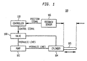
- the transducer which can be located remotely from the piston, senses the position of the translating member, and provides an electrical output signal indicating the piston's position. This signal can be conditioned and used in a feedback control system, a user interface, or any system where such a signal is desirable.
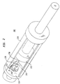
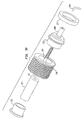
- the sensor 218 further comprises a flexible connector 216 attached to the piston 212, a converting element 220 attached to the base 214 and a transducer (not shown).
- the connector 216 also attaches to the converting element 220 and directly imparts the displacement of the piston 212 with respect to the base 214 to the converting element 220.
- the converting element 220 converts this displacement to a proportional displacement of a translating member (not shown).
- the transducer located remote from the piston, senses the position of the translating member.
- the transducer is a linear variable differential transformer (LVDT).
- LVDT linear variable differential transformer
- other types of transducers can be implemented without departing from the principles of the invention, including differential variable reluctance transducers (DVRTs®), wire wound potentiometers, conductive plastic potentiometers, inductive or capacitive sensors, Hall-effect transducers, or sensors based upon light emitting diodes, or laser light.
- the target element for the transducer affixes to the translating member.
- the sensing element is disposed to sense the position of the target element.
- the senor can also be affixed in various locations within a cylinder.
- a sensor 500 is shown attached to the cylinder end cap 503 defining the piston shaft aperture.
- the flexible connector 502 is affixed to the same side of the piston as the shaft. Operation of this configuration is the same with respect to FIGs. 2, 3A, B, and C.
Landscapes
- Engineering & Computer Science (AREA)
- Physics & Mathematics (AREA)
- Automation & Control Theory (AREA)
- Mechanical Engineering (AREA)
- General Engineering & Computer Science (AREA)
- General Physics & Mathematics (AREA)
- Fluid Mechanics (AREA)
- Measurement Of Length, Angles, Or The Like Using Electric Or Magnetic Means (AREA)
- Actuator (AREA)
- Control Of Throttle Valves Provided In The Intake System Or In The Exhaust System (AREA)
- Valve-Gear Or Valve Arrangements (AREA)
- Valve Device For Special Equipments (AREA)
- Fluid-Pressure Circuits (AREA)
- Measuring Fluid Pressure (AREA)
Abstract
Description
the sensor further comprises a translating member disposed to translate linearly within the internal opening and in cooperation with the rotation of the rotating element, the linear translation being proportional to the translation of the first element relative to the second element; and wherein
the transducer is disposed to sense a position of the translating member, the transducer providing the position-related signal.
Claims (18)
- A sensor (218) for providing a position-related signal for a first element (212) in relation to a second element (214), the sensor comprising:characterised in thata flexible connector (216) having a first end attachable to the first element (212);a rotating element (220, 310) defining an internal opening and being attachable to the second element (214) and coupled to a second end of the flexible connector (216); anda transducer (323, 704),
the sensor further comprises a translating member (324) disposed to translate linearly within the internal opening and in cooperation with the rotation of the rotating element (220, 310), the linear translation being proportional to the translation of the first element relative to the second element; and
in that the transducer (323, 704) is disposed to sense a position of the translating member (324), wherein the transducer (323, 704) provides the position-related signal. - The sensor (218) of claim 1 further comprising a recoil mechanism (428) coupled to said rotating element (220, 310) for imparting a rotational action on said rotating element (220, 310).
- The sensor (218) of any one of the preceding claims wherein said translating member (324) is in threaded communication with said rotating element (220, 310).
- The sensor (218) of any one of the preceding claims wherein said translating member (324) displaces along an axis of rotation of said rotating element (220, 310).
- The sensor (218) of any one of the preceding claims wherein said transducer (323, 704) is one selected from the group comprising a LVDT, a DVRT®, a potentiometer, an inductive transducer, a capacitive transducer, a Hall-effect transducer, an LED transducer, and a laser based transducer.
- The sensor (218) of claim 3 further including a mounting element (302) attached in fixed relation to the second element (214), said rotating element (220, 310) rotatably attached to said mounting element (302)
- The sensor (218) of any one of the preceding claims further including an anti-rotational force exerted on said translating member (324).
- The sensor (218) of any one of the preceding claims wherein the first element (212) is a piston and said second element (214) is a cylinder, said piston disposed to translate in said cylinder.
- The sensor (218) of claim 8 wherein the sensor (218) is located within the cylinder.
- The sensor (218) of claim 8 or 9 further comprising hydraulic fluid contained within said cylinder.
- The sensor (218) of any one of the preceding claims further including an anti-backlash force exerted along a longitudinal axis of said translating member (324).
- A piece of heavy equipment comprising a sensor according to claim 10.
- A method for sensing a position of a first element (212) moveable within a cylinder (200), the steps comprising:wherein the rotatable element (31) defines an internal opening,in a converting element (220) in fixed relation to the cylinder (200), converting a linear displacement of the first element (212) to an angular displacement of a rotatable element (310), and providing a transducer (323, 325, 704) disposed within the cylinder (200),
wherein the linear displacement of the first element (212) is converted to the proportional linear displacement of a second element (324) via a flexible connector (216) connected to the first element (212) and to the converting element (220) by converting said angular displacement of said rotatable element (310) to a linear displacement of said second element (324);
the method further comprises the step of sensing the linear displacement of the second element (324) with the transducer (323, 325, 704); and
wherein the second element is disposed to translate linearly within the internal opening. - The method of claim 13 wherein said transducer (323, 325, 704) is one selected from the group comprising a LVDT, a DVRT®, a potentiometer, an inductive transducer, a capacitive transducer, a Hall-effect transducer, an LED based transducer, and a laser based transducer.
- The method of claim 13 or 14 wherein said transducer (323, 325, 704) is operable to provide a position related signal.
- The method of any one of claims 13 to 15 further comprising disposing hydraulic fluid within said cylinder (200).
- The sensor of claim 5 wherein the transducer comprises an LVDT.
- The sensor of claim 5 wherein the transducer comprises a Hall-effect transducer.
Priority Applications (1)
| Application Number | Priority Date | Filing Date | Title |
|---|---|---|---|
| EP04009658A EP1443218B1 (en) | 1998-10-20 | 1999-10-18 | Precision sensor for a hydraulic cylinder |
Applications Claiming Priority (5)
| Application Number | Priority Date | Filing Date | Title |
|---|---|---|---|
| US10488698P | 1998-10-20 | 1998-10-20 | |
| US104886P | 1998-10-20 | ||
| US09/302,701 US6234061B1 (en) | 1998-10-20 | 1999-04-30 | Precision sensor for a hydraulic cylinder |
| US302701 | 1999-04-30 | ||
| PCT/US1999/024287 WO2000023717A1 (en) | 1998-10-20 | 1999-10-18 | Precision sensor for a hydraulic cylinder |
Related Child Applications (1)
| Application Number | Title | Priority Date | Filing Date |
|---|---|---|---|
| EP04009658A Division EP1443218B1 (en) | 1998-10-20 | 1999-10-18 | Precision sensor for a hydraulic cylinder |
Publications (2)
| Publication Number | Publication Date |
|---|---|
| EP1123464A1 EP1123464A1 (en) | 2001-08-16 |
| EP1123464B1 true EP1123464B1 (en) | 2005-06-15 |
Family
ID=26802046
Family Applications (1)
| Application Number | Title | Priority Date | Filing Date |
|---|---|---|---|
| EP99970715A Expired - Lifetime EP1123464B1 (en) | 1998-10-20 | 1999-10-18 | Precision sensor for a hydraulic cylinder |
Country Status (7)
| Country | Link |
|---|---|
| US (1) | US6234061B1 (en) |
| EP (1) | EP1123464B1 (en) |
| AT (2) | ATE298045T1 (en) |
| AU (1) | AU1446900A (en) |
| CA (1) | CA2346678C (en) |
| DE (2) | DE69934729T2 (en) |
| WO (1) | WO2000023717A1 (en) |
Families Citing this family (41)
| Publication number | Priority date | Publication date | Assignee | Title |
|---|---|---|---|---|
| US6694861B2 (en) * | 1998-10-19 | 2004-02-24 | Control Products Inc. | Precision sensor for a hydraulic cylinder |
| US7290476B1 (en) * | 1998-10-20 | 2007-11-06 | Control Products, Inc. | Precision sensor for a hydraulic cylinder |
| DE10028930A1 (en) * | 2000-06-10 | 2002-01-03 | Deere & Co | Harrow |
| WO2003029753A2 (en) * | 2001-10-03 | 2003-04-10 | Measurement Specialties, Inc. | Modular non-contacting position sensor |
| US7552671B2 (en) * | 2002-01-04 | 2009-06-30 | Parker-Hannifin Corporation | Cylinder with fiber optical position sensing device and method |
| US6834574B2 (en) * | 2002-01-04 | 2004-12-28 | Parker-Hannifin Corporation | Cylinder with optical position sensing device and method |
| US7093361B2 (en) * | 2002-01-23 | 2006-08-22 | Control Products, Inc. | Method of assembling an actuator with an internal sensor |
| US6866545B2 (en) * | 2003-03-10 | 2005-03-15 | Control Products, Inc., (Us) | Electrical cordset with integral signal conditioning circuitry |
| US6935204B2 (en) | 2003-10-31 | 2005-08-30 | Caterpillar Inc | Automated manual transmission and shift method |
| US7197974B2 (en) * | 2004-01-15 | 2007-04-03 | Control Products Inc. | Position sensor |
| US7609055B2 (en) * | 2004-07-21 | 2009-10-27 | Control Products, Inc. | Position sensing device and method |
| US7300289B2 (en) * | 2005-09-30 | 2007-11-27 | Control Products Inc. | Electrical cordset having connector with integral signal conditioning circuitry |
| DE102005058776B4 (en) * | 2005-12-09 | 2018-03-01 | Zf Friedrichshafen Ag | Device for controlling and / or regulating a hydraulically actuated switching element of a transmission device and transmission device |
| DE202006001807U1 (en) | 2006-02-02 | 2007-06-06 | Sensor-Technik Wiedemann Gmbh | Measuring arrangement with magnet |
| SE529291C2 (en) * | 2006-06-27 | 2007-06-19 | Hagloef Sweden Ab | Electronic tape measure comprises roller on which tape measure can be wound and unwound by rotation of roller |
| DE102006062129B4 (en) | 2006-12-22 | 2010-08-05 | Wirtgen Gmbh | Road construction machine and method for measuring the cutting depth |
| KR101468766B1 (en) * | 2008-03-10 | 2014-12-12 | 티모시 웹스터 | Position sensing of a piston in a hydraulic cylinder using a photo image sensor |
| US7982459B2 (en) * | 2008-06-30 | 2011-07-19 | Eaton Corporation | Hydraulic cylinder rod position sensing method |
| WO2010141605A1 (en) | 2009-06-03 | 2010-12-09 | Control Products Inc. | Hydraulic accumulator with position sensor |
| BE1018847A3 (en) * | 2009-07-30 | 2011-10-04 | Cnh Belgium Nv | A BALEN PRESS WITH A FRICTION SENSOR. |
| US8156798B1 (en) * | 2010-07-09 | 2012-04-17 | Hongfeng Bi | High pressure high temperature fluid densitometer |
| US8558408B2 (en) | 2010-09-29 | 2013-10-15 | General Electric Company | System and method for providing redundant power to a device |
| US20120134783A1 (en) | 2010-11-30 | 2012-05-31 | General Electric Company | System and method for operating a compressor |
| US8278779B2 (en) | 2011-02-07 | 2012-10-02 | General Electric Company | System and method for providing redundant power to a device |
| WO2014003992A1 (en) | 2012-06-26 | 2014-01-03 | Control Products, Inc. | System and method of manufacture for a linear position sensor |
| US10006763B2 (en) | 2014-06-02 | 2018-06-26 | Reel Power Licensing Corp. | Accumulator assembly fixture |
| US10279443B2 (en) | 2014-06-02 | 2019-05-07 | Reel Power Licensing Corp. | Accumulator assembly fixture |
| FR3027037B1 (en) * | 2014-10-13 | 2018-01-26 | Groupe Mecalac | TOOL HOLDER FOR CONSTRUCTION OR PUBLIC WORKS EQUIPMENT |
| CN107531297A (en) | 2015-03-25 | 2018-01-02 | 哥伦比亚车辆有限公司 | For conveying and turning to heavy duty method and apparatus |
| US10358876B2 (en) | 2015-07-22 | 2019-07-23 | Columbia Trailer Co., Inc. | Method and apparatus for transporting and steering a heavy load |
| US10113883B1 (en) | 2016-01-08 | 2018-10-30 | Control Products, Inc. | Hybrid sensor system and method of use |
| US10563678B2 (en) | 2016-08-09 | 2020-02-18 | Industries Mailhot, Inc. | Pressure vessel arrangement providing piston position feedback, pressure vessel, and method for providing piston position feedback in a pressure vessel |
| GB2554655B (en) * | 2016-09-30 | 2019-10-02 | Caterpillar Inc | A hydraulic actuator arrangement |
| CA3109051A1 (en) | 2018-08-17 | 2020-02-20 | Columbia Trailer Co., Inc. | Method and apparatus for transporting and steering a heavy load |
| US10779506B1 (en) * | 2018-10-24 | 2020-09-22 | Matthew J. Ulrich | Fully automated, sensor-driven, catch system for a hydraulic livestock squeeze chute |
| US11629735B2 (en) | 2020-01-28 | 2023-04-18 | Caterpillar Paving Products Inc. | Milling machine having a fluid flow based height measurement system |
| US11692563B2 (en) | 2020-01-28 | 2023-07-04 | Caterpillar Paving Products Inc. | Milling machine having a valve current based height measurement system |
| US11255059B2 (en) | 2020-01-28 | 2022-02-22 | Caterpillar Paving Products Inc. | Milling machine having a non-contact leg-height measurement system |
| US11578737B2 (en) | 2020-03-12 | 2023-02-14 | Caterpillar Paving Products Inc. | Distance based actuator velocity calibration system |
| US11566387B2 (en) | 2020-03-12 | 2023-01-31 | Caterpillar Paving Products Inc. | Relative velocity based actuator velocity calibration system |
| IT202100028070A1 (en) | 2021-11-04 | 2023-05-04 | Tpi S R L | “CONTACTLESS LINEAR POSITION TRANSDUCER.” |
Family Cites Families (19)
| Publication number | Priority date | Publication date | Assignee | Title |
|---|---|---|---|---|
| US3403365A (en) * | 1964-05-04 | 1968-09-24 | Gen Electric | Shielded transducer having means to reduce core movement |
| DE2635614A1 (en) | 1976-08-07 | 1978-02-09 | Georg Rudolf Sillner | Control potentiometer with external setting - has spiral groove in which contact driven by pressure element moves to change setting |
| US4121504A (en) | 1977-01-21 | 1978-10-24 | Inovec, Inc. | Cylinder positioning systems |
| US4286386A (en) * | 1977-09-06 | 1981-09-01 | Long Irvin E | Electro-mechanical displacement measuring device |
| SE419709B (en) | 1979-02-21 | 1981-08-24 | Roland Kaufeldt | SET AND DEVICE FOR ASTADCOMMATING QUICK TIME AND SOFT BRAKING AND AN EXACTLY DETERMINED FINAL ROOM WITH A GREAT ROBOT FRAME |
| US4231700A (en) | 1979-04-09 | 1980-11-04 | Spectra-Physics, Inc. | Method and apparatus for laser beam control of backhoe digging depth |
| US4288196A (en) | 1979-06-14 | 1981-09-08 | Sutton Ii James O | Computer controlled backhoe |
| US4386552A (en) * | 1980-06-16 | 1983-06-07 | Foxwell W John | Power cylinder with internally mounted position indicator |
| US4945221A (en) | 1987-04-24 | 1990-07-31 | Laser Alignment, Inc. | Apparatus and method for controlling a hydraulic excavator |
| US4841246A (en) | 1987-12-29 | 1989-06-20 | Eaton Corporation | Multiturn shaft position sensor having magnet movable with nonrotating linear moving nut |
| GB2216268B (en) | 1988-03-31 | 1992-04-15 | Schlumberger Ind Ltd | Rotary displacement transducers |
| DE3835782A1 (en) | 1988-10-20 | 1990-04-26 | Rexroth Mannesmann Gmbh | Device for measuring angles of rotation |
| JPH02186102A (en) * | 1989-01-10 | 1990-07-20 | Nakamura Koki Kk | Piston position detecting device for piston type accumulator |
| FR2674294B1 (en) | 1991-03-22 | 1993-12-17 | Etudes Montages | HYDRAULIC CYLINDER WITH MOVABLE ROD POSITIONING. |
| US5341724A (en) * | 1993-06-28 | 1994-08-30 | Bronislav Vatel | Pneumatic telescoping cylinder and method |
| US5404661A (en) | 1994-05-10 | 1995-04-11 | Caterpillar Inc. | Method and apparatus for determining the location of a work implement |
| US5694042A (en) | 1995-09-15 | 1997-12-02 | Turck, Inc. | Angular displacement sensor for rotationally reciprocating elements |
| US5701793A (en) | 1996-06-24 | 1997-12-30 | Catepillar Inc. | Method and apparatus for controlling an implement of a work machine |
| US5752811A (en) | 1996-11-15 | 1998-05-19 | Petro; John P. | Linear actuator mechanism for converting rotary to linear movement including one end pulley Line attached to the stationary anchor and other end attached to the take-up drum |
-
1999
- 1999-04-30 US US09/302,701 patent/US6234061B1/en not_active Expired - Lifetime
- 1999-10-18 AT AT99970715T patent/ATE298045T1/en not_active IP Right Cessation
- 1999-10-18 DE DE69934729T patent/DE69934729T2/en not_active Expired - Lifetime
- 1999-10-18 WO PCT/US1999/024287 patent/WO2000023717A1/en active IP Right Grant
- 1999-10-18 DE DE69925851T patent/DE69925851T2/en not_active Expired - Lifetime
- 1999-10-18 AT AT04009658T patent/ATE350588T1/en not_active IP Right Cessation
- 1999-10-18 EP EP99970715A patent/EP1123464B1/en not_active Expired - Lifetime
- 1999-10-18 AU AU14469/00A patent/AU1446900A/en not_active Abandoned
- 1999-10-18 CA CA002346678A patent/CA2346678C/en not_active Expired - Lifetime
Also Published As
| Publication number | Publication date |
|---|---|
| CA2346678C (en) | 2007-11-20 |
| WO2000023717A1 (en) | 2000-04-27 |
| ATE350588T1 (en) | 2007-01-15 |
| WO2000023717A9 (en) | 2001-02-01 |
| DE69934729T2 (en) | 2007-10-18 |
| AU1446900A (en) | 2000-05-08 |
| DE69925851T2 (en) | 2006-05-11 |
| DE69925851D1 (en) | 2005-07-21 |
| EP1123464A1 (en) | 2001-08-16 |
| US6234061B1 (en) | 2001-05-22 |
| DE69934729D1 (en) | 2007-02-15 |
| ATE298045T1 (en) | 2005-07-15 |
| CA2346678A1 (en) | 2000-04-27 |
Similar Documents
| Publication | Publication Date | Title |
|---|---|---|
| EP1123464B1 (en) | Precision sensor for a hydraulic cylinder | |
| US6694861B2 (en) | Precision sensor for a hydraulic cylinder | |
| US7290476B1 (en) | Precision sensor for a hydraulic cylinder | |
| US8827046B2 (en) | Brake wear measurement system | |
| CN101567601B (en) | Actuating device with controllable stroke | |
| CA1173530A (en) | Power cylinder with internally mounted position indicator | |
| US8074451B2 (en) | Electric motor actuation of a hydrostatic pump | |
| CN100358685C (en) | Pipeline processing structure of an industrial robot | |
| JPH0424950B2 (en) | ||
| US20110254394A1 (en) | Electric Motor for Roto-Linear Actuator | |
| JPH01226697A (en) | Operating reaction force controller for winch | |
| EP2019036A2 (en) | Control device for watercrafts | |
| EP2864646B1 (en) | System and method of manufacture for a linear position sensor | |
| EP1443218B1 (en) | Precision sensor for a hydraulic cylinder | |
| CN110842968A (en) | Antagonistic driving device adopting capstan and tendon transmission | |
| CN201396328Y (en) | Hydraulic valve control device | |
| KR100311836B1 (en) | Actuating System for Accelerator | |
| CN209231808U (en) | A kind of swing arm electronic hand throttle | |
| US4854189A (en) | Rotary/linear actuator | |
| US3878738A (en) | Actuator for a transmission modulator valve | |
| US20190366534A1 (en) | Robotic Arm Assembly | |
| KR102284710B1 (en) | Linear actuator | |
| CN110701215B (en) | Electric control electric rotor wing braking system | |
| CN220864056U (en) | Joint limb and robot | |
| KR200414483Y1 (en) | Robust Actuator |
Legal Events
| Date | Code | Title | Description |
|---|---|---|---|
| PUAI | Public reference made under article 153(3) epc to a published international application that has entered the european phase |
Free format text: ORIGINAL CODE: 0009012 |
|
| 17P | Request for examination filed |
Effective date: 20010501 |
|
| AK | Designated contracting states |
Kind code of ref document: A1 Designated state(s): AT BE CH CY DE DK ES FI FR GB GR IE IT LI LU MC NL PT SE |
|
| AX | Request for extension of the european patent |
Free format text: AL;LT;LV;MK;RO;SI |
|
| 17Q | First examination report despatched |
Effective date: 20021122 |
|
| GRAP | Despatch of communication of intention to grant a patent |
Free format text: ORIGINAL CODE: EPIDOSNIGR1 |
|
| GRAS | Grant fee paid |
Free format text: ORIGINAL CODE: EPIDOSNIGR3 |
|
| GRAA | (expected) grant |
Free format text: ORIGINAL CODE: 0009210 |
|
| AK | Designated contracting states |
Kind code of ref document: B1 Designated state(s): AT BE CH CY DE DK ES FI FR GB GR IE IT LI LU MC NL PT SE |
|
| PG25 | Lapsed in a contracting state [announced via postgrant information from national office to epo] |
Ref country code: NL Free format text: LAPSE BECAUSE OF FAILURE TO SUBMIT A TRANSLATION OF THE DESCRIPTION OR TO PAY THE FEE WITHIN THE PRESCRIBED TIME-LIMIT Effective date: 20050615 Ref country code: LI Free format text: LAPSE BECAUSE OF FAILURE TO SUBMIT A TRANSLATION OF THE DESCRIPTION OR TO PAY THE FEE WITHIN THE PRESCRIBED TIME-LIMIT Effective date: 20050615 Ref country code: FI Free format text: LAPSE BECAUSE OF FAILURE TO SUBMIT A TRANSLATION OF THE DESCRIPTION OR TO PAY THE FEE WITHIN THE PRESCRIBED TIME-LIMIT Effective date: 20050615 Ref country code: CH Free format text: LAPSE BECAUSE OF FAILURE TO SUBMIT A TRANSLATION OF THE DESCRIPTION OR TO PAY THE FEE WITHIN THE PRESCRIBED TIME-LIMIT Effective date: 20050615 Ref country code: BE Free format text: LAPSE BECAUSE OF FAILURE TO SUBMIT A TRANSLATION OF THE DESCRIPTION OR TO PAY THE FEE WITHIN THE PRESCRIBED TIME-LIMIT Effective date: 20050615 Ref country code: AT Free format text: LAPSE BECAUSE OF FAILURE TO SUBMIT A TRANSLATION OF THE DESCRIPTION OR TO PAY THE FEE WITHIN THE PRESCRIBED TIME-LIMIT Effective date: 20050615 |
|
| REG | Reference to a national code |
Ref country code: GB Ref legal event code: FG4D Ref country code: CH Ref legal event code: EP |
|
| REF | Corresponds to: |
Ref document number: 69925851 Country of ref document: DE Date of ref document: 20050721 Kind code of ref document: P |
|
| REG | Reference to a national code |
Ref country code: IE Ref legal event code: FG4D |
|
| PG25 | Lapsed in a contracting state [announced via postgrant information from national office to epo] |
Ref country code: SE Free format text: LAPSE BECAUSE OF FAILURE TO SUBMIT A TRANSLATION OF THE DESCRIPTION OR TO PAY THE FEE WITHIN THE PRESCRIBED TIME-LIMIT Effective date: 20050915 Ref country code: GR Free format text: LAPSE BECAUSE OF FAILURE TO SUBMIT A TRANSLATION OF THE DESCRIPTION OR TO PAY THE FEE WITHIN THE PRESCRIBED TIME-LIMIT Effective date: 20050915 Ref country code: DK Free format text: LAPSE BECAUSE OF FAILURE TO SUBMIT A TRANSLATION OF THE DESCRIPTION OR TO PAY THE FEE WITHIN THE PRESCRIBED TIME-LIMIT Effective date: 20050915 |
|
| PG25 | Lapsed in a contracting state [announced via postgrant information from national office to epo] |
Ref country code: ES Free format text: LAPSE BECAUSE OF FAILURE TO SUBMIT A TRANSLATION OF THE DESCRIPTION OR TO PAY THE FEE WITHIN THE PRESCRIBED TIME-LIMIT Effective date: 20050926 |
|
| PG25 | Lapsed in a contracting state [announced via postgrant information from national office to epo] |
Ref country code: IE Free format text: LAPSE BECAUSE OF NON-PAYMENT OF DUE FEES Effective date: 20051018 Ref country code: CY Free format text: LAPSE BECAUSE OF FAILURE TO SUBMIT A TRANSLATION OF THE DESCRIPTION OR TO PAY THE FEE WITHIN THE PRESCRIBED TIME-LIMIT Effective date: 20051018 |
|
| PG25 | Lapsed in a contracting state [announced via postgrant information from national office to epo] |
Ref country code: MC Free format text: LAPSE BECAUSE OF NON-PAYMENT OF DUE FEES Effective date: 20051031 Ref country code: LU Free format text: LAPSE BECAUSE OF NON-PAYMENT OF DUE FEES Effective date: 20051031 |
|
| PG25 | Lapsed in a contracting state [announced via postgrant information from national office to epo] |
Ref country code: PT Free format text: LAPSE BECAUSE OF FAILURE TO SUBMIT A TRANSLATION OF THE DESCRIPTION OR TO PAY THE FEE WITHIN THE PRESCRIBED TIME-LIMIT Effective date: 20051124 |
|
| NLV1 | Nl: lapsed or annulled due to failure to fulfill the requirements of art. 29p and 29m of the patents act | ||
| REG | Reference to a national code |
Ref country code: CH Ref legal event code: PL |
|
| ET | Fr: translation filed | ||
| PLBE | No opposition filed within time limit |
Free format text: ORIGINAL CODE: 0009261 |
|
| STAA | Information on the status of an ep patent application or granted ep patent |
Free format text: STATUS: NO OPPOSITION FILED WITHIN TIME LIMIT |
|
| 26N | No opposition filed |
Effective date: 20060316 |
|
| REG | Reference to a national code |
Ref country code: IE Ref legal event code: MM4A |
|
| REG | Reference to a national code |
Ref country code: FR Ref legal event code: PLFP Year of fee payment: 17 |
|
| REG | Reference to a national code |
Ref country code: FR Ref legal event code: PLFP Year of fee payment: 18 |
|
| REG | Reference to a national code |
Ref country code: FR Ref legal event code: PLFP Year of fee payment: 19 |
|
| REG | Reference to a national code |
Ref country code: FR Ref legal event code: PLFP Year of fee payment: 20 |
|
| PGFP | Annual fee paid to national office [announced via postgrant information from national office to epo] |
Ref country code: DE Payment date: 20181029 Year of fee payment: 20 |
|
| PGFP | Annual fee paid to national office [announced via postgrant information from national office to epo] |
Ref country code: IT Payment date: 20181023 Year of fee payment: 20 Ref country code: GB Payment date: 20181029 Year of fee payment: 20 Ref country code: FR Payment date: 20181025 Year of fee payment: 20 |
|
| REG | Reference to a national code |
Ref country code: DE Ref legal event code: R071 Ref document number: 69925851 Country of ref document: DE |
|
| REG | Reference to a national code |
Ref country code: GB Ref legal event code: PE20 Expiry date: 20191017 |
|
| PG25 | Lapsed in a contracting state [announced via postgrant information from national office to epo] |
Ref country code: GB Free format text: LAPSE BECAUSE OF EXPIRATION OF PROTECTION Effective date: 20191017 |