EP1443205A2 - Fuel supply system for internal combustion engine and fuel transfer tube - Google Patents
Fuel supply system for internal combustion engine and fuel transfer tube Download PDFInfo
- Publication number
- EP1443205A2 EP1443205A2 EP20040001996 EP04001996A EP1443205A2 EP 1443205 A2 EP1443205 A2 EP 1443205A2 EP 20040001996 EP20040001996 EP 20040001996 EP 04001996 A EP04001996 A EP 04001996A EP 1443205 A2 EP1443205 A2 EP 1443205A2
- Authority
- EP
- European Patent Office
- Prior art keywords
- fuel
- transfer tube
- internal combustion
- combustion engine
- supply system
- Prior art date
- Legal status (The legal status is an assumption and is not a legal conclusion. Google has not performed a legal analysis and makes no representation as to the accuracy of the status listed.)
- Withdrawn
Links
Images


Classifications
-
- F—MECHANICAL ENGINEERING; LIGHTING; HEATING; WEAPONS; BLASTING
- F02—COMBUSTION ENGINES; HOT-GAS OR COMBUSTION-PRODUCT ENGINE PLANTS
- F02M—SUPPLYING COMBUSTION ENGINES IN GENERAL WITH COMBUSTIBLE MIXTURES OR CONSTITUENTS THEREOF
- F02M37/00—Apparatus or systems for feeding liquid fuel from storage containers to carburettors or fuel-injection apparatus; Arrangements for purifying liquid fuel specially adapted for, or arranged on, internal-combustion engines
- F02M37/0076—Details of the fuel feeding system related to the fuel tank
- F02M37/0088—Multiple separate fuel tanks or tanks being at least partially partitioned
- F02M37/0094—Saddle tanks; Tanks having partition walls
-
- F—MECHANICAL ENGINEERING; LIGHTING; HEATING; WEAPONS; BLASTING
- F02—COMBUSTION ENGINES; HOT-GAS OR COMBUSTION-PRODUCT ENGINE PLANTS
- F02M—SUPPLYING COMBUSTION ENGINES IN GENERAL WITH COMBUSTIBLE MIXTURES OR CONSTITUENTS THEREOF
- F02M37/00—Apparatus or systems for feeding liquid fuel from storage containers to carburettors or fuel-injection apparatus; Arrangements for purifying liquid fuel specially adapted for, or arranged on, internal-combustion engines
- F02M37/0011—Constructional details; Manufacturing or assembly of elements of fuel systems; Materials therefor
- F02M37/0017—Constructional details; Manufacturing or assembly of elements of fuel systems; Materials therefor related to fuel pipes or their connections, e.g. joints or sealings
-
- F—MECHANICAL ENGINEERING; LIGHTING; HEATING; WEAPONS; BLASTING
- F02—COMBUSTION ENGINES; HOT-GAS OR COMBUSTION-PRODUCT ENGINE PLANTS
- F02M—SUPPLYING COMBUSTION ENGINES IN GENERAL WITH COMBUSTIBLE MIXTURES OR CONSTITUENTS THEREOF
- F02M37/00—Apparatus or systems for feeding liquid fuel from storage containers to carburettors or fuel-injection apparatus; Arrangements for purifying liquid fuel specially adapted for, or arranged on, internal-combustion engines
- F02M37/0011—Constructional details; Manufacturing or assembly of elements of fuel systems; Materials therefor
- F02M37/0041—Means for damping pressure pulsations
-
- F—MECHANICAL ENGINEERING; LIGHTING; HEATING; WEAPONS; BLASTING
- F02—COMBUSTION ENGINES; HOT-GAS OR COMBUSTION-PRODUCT ENGINE PLANTS
- F02M—SUPPLYING COMBUSTION ENGINES IN GENERAL WITH COMBUSTIBLE MIXTURES OR CONSTITUENTS THEREOF
- F02M37/00—Apparatus or systems for feeding liquid fuel from storage containers to carburettors or fuel-injection apparatus; Arrangements for purifying liquid fuel specially adapted for, or arranged on, internal-combustion engines
- F02M37/02—Feeding by means of suction apparatus, e.g. by air flow through carburettors
- F02M37/025—Feeding by means of a liquid fuel-driven jet pump
-
- Y—GENERAL TAGGING OF NEW TECHNOLOGICAL DEVELOPMENTS; GENERAL TAGGING OF CROSS-SECTIONAL TECHNOLOGIES SPANNING OVER SEVERAL SECTIONS OF THE IPC; TECHNICAL SUBJECTS COVERED BY FORMER USPC CROSS-REFERENCE ART COLLECTIONS [XRACs] AND DIGESTS
- Y10—TECHNICAL SUBJECTS COVERED BY FORMER USPC
- Y10T—TECHNICAL SUBJECTS COVERED BY FORMER US CLASSIFICATION
- Y10T137/00—Fluid handling
- Y10T137/8593—Systems
- Y10T137/85978—With pump
- Y10T137/86075—And jet-aspiration type pump
-
- Y—GENERAL TAGGING OF NEW TECHNOLOGICAL DEVELOPMENTS; GENERAL TAGGING OF CROSS-SECTIONAL TECHNOLOGIES SPANNING OVER SEVERAL SECTIONS OF THE IPC; TECHNICAL SUBJECTS COVERED BY FORMER USPC CROSS-REFERENCE ART COLLECTIONS [XRACs] AND DIGESTS
- Y10—TECHNICAL SUBJECTS COVERED BY FORMER USPC
- Y10T—TECHNICAL SUBJECTS COVERED BY FORMER US CLASSIFICATION
- Y10T137/00—Fluid handling
- Y10T137/8593—Systems
- Y10T137/86187—Plural tanks or compartments connected for serial flow
Definitions
- the present invention relates to a fuel supply system for an internal combustion engine, which is disposed in a saddle type fuel tank provided with a main chamber and an auxiliary chamber on both sides of an upwardly protruding center portion of a bottom face thereof, for transferring fuel in the auxiliary chamber side to the main chamber side, and a fuel transfer tube used for the transfer of the fuel.
- a propeller shaft for driving rear wheels is disposed on a center part of an automotive body to extend in a longitudinal direction. Therefore, in this kind of vehicle, a bottom face of a fuel tank arranged on a bottom portion of the automotive body is formed in a shape bypassing to surround the propeller shaft, that is, in a saddle shape, so as to enlarge the tank volume as much as possible.
- the fuel tank is divided into a main chamber into which fuel is sucked by a fuel pump and an auxiliary chamber having no suction hole, by a protruding bottom face bypassing to surround the propeller shat. Therefore, when the fuel level is lowered as a result of fuel consumption, generally, the fuel from the auxiliary chamber is supplied to the main chamber by a negative pressure of return fuel, a so-called jet pump.
- the jet pump is disposed on an outlet of a fuel return pipe, so that the fuel from the auxiliary chamber is sucked into the main chamber via a fuel transfer tube connected to the jet pump, by the negative pressure with the discharge of return fuel from a discharge port of the jet pump.
- the fuel transfer tube needs to be mounted by being bent to lie over the protruding bottom face of the saddle type fuel tank.
- the rigidity thereof is insufficient, and therefore, there occurs an abrasion noise when the tube interferes the inner wall of the tank due to the fuel vibration in the tank.
- the present invention has been accomplished in view of the above problems and has an object to enable the rigidity to be ensured while suppressing the occurrence of noise, in a fuel supply system for an internal combustion engine and a fuel transfer tube, which are applied to a saddle type fuel tank.
- a fuel supply system for an internal combustion engine is constituted so that a fuel transfer tube mounted so as to lie over a protruding portion of a saddle type fuel tank, is connected to a fuel introduction port of a jet pump disposed on a main chamber side of the fuel tank, to suck fuel inside an auxiliary chamber into the main chamber via the fuel transfer tube, and also at least a part of the fuel transfer tube is constituted by arranging alternately a plurality of bellows portions each of which cross section is changed, and a plurality of straight portions each of which cross section is fixed.
- a fuel transfer tube according to the present invention is constituted so that a bellows portion of which cross section is changed and a straight portion of which cross section is fixed, are arranged alternately.
- a fuel tank 1 disposed on a rear-wheel-drive vehicle or a four-wheel-drive vehicle is formed such that a center portion 1a of a bottom face thereof protrudes upwardly so as to bypass a propeller shaft, and is provided with a main chamber 1b and an auxiliary chamber 1c on both sides of protruding portion 1a.
- a pump unit 2 incorporating therein a pump body 20 is installed in main chamber 1b, and a jet pump 21 is mounted on a bottom portion of pump unit 2.
- Jet pump 21 includes a negative pressure chamber 23 in a housing 22, and a narrowed diameter portion 24 and a fuel injection nozzle 25 are formed on one side of jet pump 21. Further, an approximately L-shaped nozzle member 26 is disposed in negative pressure chamber 23. A horizontal end of nozzle member 26 is formed in a tapered shape to serve as a nozzle hole 27. Nozzle hole 27 is located in narrowed diameter portion 24 with required clearance, to form a negative pressure generating portion 28 on a boundary portion between narrowed diameter portion 24 and fuel injection nozzle 25. Further, to a vertical inlet end 29 of nozzle member 26, a fuel return pipe 3 returning fuel from an engine is connected.
- a fuel outlet 4b of a fuel transfer tube 4 according to the present invention is connected to a fuel introduction port 30 formed on housing 22, and a fuel inlet 4a of fuel transfer tube 4 is connected to a lower wall of a fuel-flow gauge 5 installed in auxiliary chamber 1c.
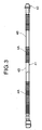
- Fuel transfer tube 4 is formed of resin material as a whole, and is constituted by arranging alternately a plurality of bellows portions 4A each of which cross section is changed, and a plurality of straight portions 4B each of which cross section is fixed.
- the bottom portion of pump unit 2 communicates with a fuel suction port of pump body 20 via a fuel suction pipe 31, and a fuel discharge port of pump body 20 is connected to a fuel supply pipe 6 supplying the fuel to the engine (refer to Fig. 1).
- auxiliary chamber 1c The fuel transferred from auxiliary chamber 1c is ejected to the bottom portion of pump unit 2 from fuel injection nozzle 25 together with the return fuel, and then pumped into pump body 20 via fuel suction pipe 31 and discharged from pump body 20, to be supplied to the engine via fuel supply pipe 6.
- the fuel in main chamber 1b flows together the fuel from auxiliary chamber 1c and pumped into pump body 20, to be supplied to the engine, by a jet pump also installed in pump unit 21 or by communicating main chamber 1b with negative pressure chamber of jet pump 21 via a pipe.
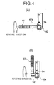
- Fig. 4 shows embodiments of mounting structure of fuel inlet 4a of fuel transfer tube 4 to a lower wall of fuel-flow gauge 5.
- a fuel inlet of fuel transfer tube is press fitted into a mounting hole formed on a wall of fuel-flow gauge.
- the excessive stress exerts on the fuel transfer tube or a connected part thereof. Since there is a restriction on the mounting direction, it is impossible to obtain the efficiency in mounting workability, maintenance performance and detachability.
- a single-touch attachable connector member 42 is press fitted into an end portion on fuel inlet side of a body 41 of fuel transfer tube 4.
- a claw 42a of ratchet structure in a spring mechanism disposed on a tip portion of connector member 42 which is to be inserted into a mounting hole 5a, is retracted to the inner side to allow the tip portion to be inserted into mounting hole 5a when the tip portion is inserted into mounting hole 5a, and after completion of the insertion in which a flange 42b disposed rearward claw 42a comes in contact with a lower wall of fuel-flow gauge 5 to be locked, claw 42a projects so that connector member 42 is retained.
- connecting member 42 By forming a diameter of the portion of connecting member 42, which is in engagement with mounting hole 5a, to be slightly smaller than that of mounting hole 5a, connecting member 42 can be axially rotated. Thus, it is possible to prevent the excessive stress from exerting on fuel transfer tube 4 and pump unit 2 being the connected part thereof, and fuel-flow gauge 5. As a result, since the restriction on the mounting direction is eliminated, the mounting workability, maintenance performance and detachability can be significantly improved.
- the mounting structure shown in (B) of Fig. 4 shows fuel transfer tube 4 in which connector member 42 is bent into an L-shape.
- This mounting structure achieves an effect similar to that in the mounting structure in (A). Further, this mounting structure is advantageous in the case where the install space for fuel transfer tube 4 is narrow, such as, the case where fuel-flow gauge 5 is disposed closer to protruding portion 1a of saddle type fuel tank 1.
- the bellows portions and the straight portions are arranged alternately over the entire fuel transfer tube.
- the bellows portions and the straight portions made of resin material may be arranged alternately on the main chamber side only.
Landscapes
- Engineering & Computer Science (AREA)
- Chemical & Material Sciences (AREA)
- Combustion & Propulsion (AREA)
- Mechanical Engineering (AREA)
- General Engineering & Computer Science (AREA)
- Fuel-Injection Apparatus (AREA)
- Rigid Pipes And Flexible Pipes (AREA)
- Cooling, Air Intake And Gas Exhaust, And Fuel Tank Arrangements In Propulsion Units (AREA)
- Jet Pumps And Other Pumps (AREA)
Abstract
Description
- The present invention relates to a fuel supply system for an internal combustion engine, which is disposed in a saddle type fuel tank provided with a main chamber and an auxiliary chamber on both sides of an upwardly protruding center portion of a bottom face thereof, for transferring fuel in the auxiliary chamber side to the main chamber side, and a fuel transfer tube used for the transfer of the fuel.
- In a rear-wheel-drive vehicle or a four-wheel-drive vehicle, a propeller shaft for driving rear wheels is disposed on a center part of an automotive body to extend in a longitudinal direction. Therefore, in this kind of vehicle, a bottom face of a fuel tank arranged on a bottom portion of the automotive body is formed in a shape bypassing to surround the propeller shaft, that is, in a saddle shape, so as to enlarge the tank volume as much as possible.
- In such a saddle type fuel tank, as disclosed in Japanese Unexamined Patent Publication No 2000-275526, the fuel tank is divided into a main chamber into which fuel is sucked by a fuel pump and an auxiliary chamber having no suction hole, by a protruding bottom face bypassing to surround the propeller shat. Therefore, when the fuel level is lowered as a result of fuel consumption, generally, the fuel from the auxiliary chamber is supplied to the main chamber by a negative pressure of return fuel, a so-called jet pump.
- Namely, the jet pump is disposed on an outlet of a fuel return pipe, so that the fuel from the auxiliary chamber is sucked into the main chamber via a fuel transfer tube connected to the jet pump, by the negative pressure with the discharge of return fuel from a discharge port of the jet pump.
- Here, the fuel transfer tube needs to be mounted by being bent to lie over the protruding bottom face of the saddle type fuel tank.
- For this purpose, there is a fuel transfer tube formed in the shape of bellows as a whole. In this case, when the fuel in the auxiliary chamber is reduced and then the jet pump starts to pump the air therein, the airflow is detached from an inner wall face of bellows shape to be turbulence. As a result, the air is vibrated to occur a noise.
- Note, there is a fuel transfer tube in which a bellows tube made of resin is connected to an end portion on the side of main chamber made of metal pipe bent from the auxiliary chamber side to lie over the protruding portion. Even in such a case, sometimes, a noise occurs from the bellows tube, resulting in the large level of noise.
- Further, especially in the fuel transfer tube the entire of which is formed in bellows shape, the rigidity thereof is insufficient, and therefore, there occurs an abrasion noise when the tube interferes the inner wall of the tank due to the fuel vibration in the tank.
- The present invention has been accomplished in view of the above problems and has an object to enable the rigidity to be ensured while suppressing the occurrence of noise, in a fuel supply system for an internal combustion engine and a fuel transfer tube, which are applied to a saddle type fuel tank.
- In order to achieve the above object, a fuel supply system for an internal combustion engine according to the present invention is constituted so that a fuel transfer tube mounted so as to lie over a protruding portion of a saddle type fuel tank, is connected to a fuel introduction port of a jet pump disposed on a main chamber side of the fuel tank, to suck fuel inside an auxiliary chamber into the main chamber via the fuel transfer tube, and also at least a part of the fuel transfer tube is constituted by arranging alternately a plurality of bellows portions each of which cross section is changed, and a plurality of straight portions each of which cross section is fixed.
- Further, a fuel transfer tube according to the present invention is constituted so that a bellows portion of which cross section is changed and a straight portion of which cross section is fixed, are arranged alternately.
- The other objects and features of this invention will become understood from the following description with reference to the accompanying drawings.
-
- Fig. 1 is a configuration diagram showing an embodiment of a fuel supply system for an internal combustion engine according to the present invention.
- Fig. 2 is an enlarged diagram showing a configuration of a jet pump periphery in the embodiment.
- Fig. 3 is a diagram showing an appearance of a fuel transfer tube according to the present invention used for the embodiment.
- Fig. 4 is a diagram showing two examples of mounting structure of the fuel transfer tube to a fuel-flow gauge.
-
- A specific embodiment of a fuel supply system according to the present invention will be described based on the drawings.
- A fuel tank 1 disposed on a rear-wheel-drive vehicle or a four-wheel-drive vehicle is formed such that a
center portion 1a of a bottom face thereof protrudes upwardly so as to bypass a propeller shaft, and is provided with amain chamber 1b and anauxiliary chamber 1c on both sides of protrudingportion 1a. - A
pump unit 2 incorporating therein apump body 20 is installed inmain chamber 1b, and ajet pump 21 is mounted on a bottom portion ofpump unit 2. -
Jet pump 21 includes anegative pressure chamber 23 in ahousing 22, and a narroweddiameter portion 24 and afuel injection nozzle 25 are formed on one side ofjet pump 21. Further, an approximately L-shaped nozzle member 26 is disposed innegative pressure chamber 23. A horizontal end ofnozzle member 26 is formed in a tapered shape to serve as anozzle hole 27.Nozzle hole 27 is located in narroweddiameter portion 24 with required clearance, to form a negativepressure generating portion 28 on a boundary portion between narroweddiameter portion 24 andfuel injection nozzle 25. Further, to avertical inlet end 29 ofnozzle member 26, a fuel return pipe 3 returning fuel from an engine is connected. - A
fuel outlet 4b of afuel transfer tube 4 according to the present invention is connected to afuel introduction port 30 formed onhousing 22, and afuel inlet 4a offuel transfer tube 4 is connected to a lower wall of a fuel-flow gauge 5 installed inauxiliary chamber 1c.Fuel transfer tube 4 is formed of resin material as a whole, and is constituted by arranging alternately a plurality ofbellows portions 4A each of which cross section is changed, and a plurality ofstraight portions 4B each of which cross section is fixed. - The bottom portion of
pump unit 2 communicates with a fuel suction port ofpump body 20 via afuel suction pipe 31, and a fuel discharge port ofpump body 20 is connected to afuel supply pipe 6 supplying the fuel to the engine (refer to Fig. 1). - Next, a basic fuel supply operation of fuel supply system having the above configuration will be described.
- When the fuel returned from fuel return pipe 3 is injected from
nozzle hole 27 ofnozzle member 26, a negative pressure is generated in negativepressure generating portion 28 due to an ejector effect so thatnegative pressure chamber 23 becomes under a negative pressure. As a result, the fuel retained inauxiliary chamber 1c is sucked bynegative chamber 23 to be transferred viafuel transfer tube 4 tomain chamber 1b. - The fuel transferred from
auxiliary chamber 1c is ejected to the bottom portion ofpump unit 2 fromfuel injection nozzle 25 together with the return fuel, and then pumped intopump body 20 viafuel suction pipe 31 and discharged frompump body 20, to be supplied to the engine viafuel supply pipe 6. - The fuel in
main chamber 1b flows together the fuel fromauxiliary chamber 1c and pumped intopump body 20, to be supplied to the engine, by a jet pump also installed inpump unit 21 or by communicatingmain chamber 1b with negative pressure chamber ofjet pump 21 via a pipe. - Next, the effect obtained by disposing
fuel transfer tube 4 according to the present invention will be described. - When the fuel level is lowered as a result that the fuel in
auxiliary chamber 1c is reduced by pumping to transfer the fuel inauxiliary chamber 1c byjet pump 21 in the above described manner,fuel inlet 4a offuel transfer tube 4 is exposed to the air, to start to suck the air therein. - In such a case, if the length of bellows portion is long as in the conventional technique, the airflow is detached from an inner wall face of bellows shape to be turbulence. As a result, the air is vibrated to occur a noise. However, in the present invention, since
fuel transfer tube 4 is constituted by arranging alternately the plurality ofbellows portions 4A and the plurality ofstraight portions 4B, the length of each bellows portion is made short, thereby enabling to suppress the cause of noise occurrence. Further, even in the case where the airflow is detached from the inner wall face ofbellows portion 4A, the airflow is again adjusted instraight portion 4B disposed downstream ofbellows portion 4A, thereby enabling to efficiently prevent the noise occurrence. - Further, since the rigidity is ensured by
straight portion 4B, it is possible to prevent an abrasion noise from occurring when the tube interferes the inner wall of the tank due to the fuel vibration. - Fig. 4 shows embodiments of mounting structure of
fuel inlet 4a offuel transfer tube 4 to a lower wall of fuel-flow gauge 5. In the conventional technique, a fuel inlet of fuel transfer tube is press fitted into a mounting hole formed on a wall of fuel-flow gauge. However, in such a press fitting method, if there occurs a deviation in mounting direction, the excessive stress exerts on the fuel transfer tube or a connected part thereof. Since there is a restriction on the mounting direction, it is impossible to obtain the efficiency in mounting workability, maintenance performance and detachability. - Therefore, in the mounting structure shown in (A) of Fig. 4, a single-touch
attachable connector member 42 is press fitted into an end portion on fuel inlet side of abody 41 offuel transfer tube 4. Inconnector member 42, aclaw 42a of ratchet structure in a spring mechanism, disposed on a tip portion ofconnector member 42 which is to be inserted into amounting hole 5a, is retracted to the inner side to allow the tip portion to be inserted intomounting hole 5a when the tip portion is inserted intomounting hole 5a, and after completion of the insertion in which a flange 42b disposed rearwardclaw 42a comes in contact with a lower wall of fuel-flow gauge 5 to be locked,claw 42a projects so thatconnector member 42 is retained. - Further, by forming a diameter of the portion of connecting
member 42, which is in engagement withmounting hole 5a, to be slightly smaller than that ofmounting hole 5a, connectingmember 42 can be axially rotated. Thus, it is possible to prevent the excessive stress from exerting onfuel transfer tube 4 andpump unit 2 being the connected part thereof, and fuel-flow gauge 5. As a result, since the restriction on the mounting direction is eliminated, the mounting workability, maintenance performance and detachability can be significantly improved. - The mounting structure shown in (B) of Fig. 4 shows
fuel transfer tube 4 in whichconnector member 42 is bent into an L-shape. This mounting structure achieves an effect similar to that in the mounting structure in (A). Further, this mounting structure is advantageous in the case where the install space forfuel transfer tube 4 is narrow, such as, the case where fuel-flow gauge 5 is disposed closer to protrudingportion 1a of saddle type fuel tank 1. - In the embodiments as shown in the above, the bellows portions and the straight portions are arranged alternately over the entire fuel transfer tube. However, in such a constitution where a portion on the auxiliary chamber side and a portion lying over the protruding portion (except for connector portion) are formed of a metal pipe, the bellows portions and the straight portions made of resin material may be arranged alternately on the main chamber side only.
- The entire contents of Japanese Patent Application No. 2003-020213 filed January 29, 2003, a priority of which is claimed, are incorporated herein by reference.
- While only selected embodiments have been chosen to illustrate the present invention, it will be apparent to those skilled in the art from this disclosure that various changes and modifications can be made herein without departing from the scope of the invention as defined in the appended claims.
- Furthermore, the foregoing description of the embodiment according to the present invention is provided for illustration only, and not for the purpose of limiting the invention as defined in the appended claims and their equivalents.
Claims (16)
- A fuel supply system for an internal combustion engine, comprising:a saddle type fuel tank provided with a main chamber and an auxiliary chamber on both sides of an upwardly protruding center portion of a bottom face thereof;a fuel return pipe returning fuel from an engine body to said fuel tank;a jet pump having a function for pumping the fuel to a main chamber side of said fuel tank by utilizing a negative pressure occurring due to a fuel ejection pressure from an outlet of said fuel return pipe; anda fuel transfer tube with one end portion connected to a fuel introduction port of said jet pump and the other end portion mounted to lie over said protruding portion, to face said auxiliary chamber,said system characterized in that at least a part of said fuel transfer tube is formed by arranging alternately a plurality of bellows portions each of which cross section is changed, and a plurality of straight portions each, of which cross section is fixed.
- A fuel supply system for an internal combustion engine according to claim 1,
wherein said other end portion which faces said auxiliary chamber, of said fuel transfer tube is constituted by a connecter member which is inserted in a single-touch into a mounting hole formed on a mounting member for mounting said other end portion, to be retained. - A fuel supply system for an internal combustion engine according to claim 2,
wherein said connector member is formed to be axially rotatable relative to said mounting hole. - A fuel supply system for an internal combustion engine according to claim 2 or 3,
wherein said connector member is formed in an L-shape consisting of a mounting portion mounted to said mounting hole to extend axially and a bent portion bent at a right angle from said mounting portion. - A fuel supply system for an internal combustion engine according to any one of claims 1 to 4,
wherein the entirety of said fuel transfer tube is formed of resin material. - A fuel supply system for an internal combustion engine according to any one of claims 1 to 5,
wherein said fuel transfer tube is formed by arranging alternately the bellows portions and straight portions on a main chamber side only. - A fuel supply system for an internal combustion engine according to claim 6,
wherein in said fuel transfer tube, a portion on the main chamber side is formed of resin material, and a portion of said fuel transfer tube on an auxiliary chamber side and a portion lying over said protruding portion are mainly formed of metal material. - A fuel supply system for an internal combustion engine according to any one of claims 1 to 7,
wherein said other end portion which faces said auxiliary chamber, of said fuel transfer tube is mounted to a fuel outlet of a fuel filter to introduce fuel via said fuel filter. - A fuel supply system for an internal combustion engine according to any one of claims 1 to 8,
wherein said jet pump together with a pump body discharging fuel to said engine is incorporated in a pump unit. - A fuel transfer tube connected to a fuel inlet of a fuel pump disposed in a fuel tank of an internal combustion engine,
said fuel transfer tube characterized of being formed by arranging alternately bellows portions each of which cross section is changed, and straight portions each of which cross section is fixed. - A fuel transfer tube according to claim 10,
wherein said fuel tank is a saddle type fuel tank provided with a main chamber and an auxiliary chamber on both sides of an upwardly protruding center portion of a bottom face thereof, and an end portion on a main chamber side is a jet pump having a function for pumping fuel by utilizing a negative pressure occurring due to a fuel ejection pressure from an outlet of a fuel return pipe. - A fuel transfer tube according to claim 10 or 11,
wherein one end portion of said fuel transfer tube, being a fuel inlet on an opposite side of a fuel pump connection side, is constituted by a connecter member which is inserted in a single-touch into a mounting hole formed on a mounting member for mounting said one end portion, to be retained. - A fuel transfer tube according to claim 12,
wherein said connector member is formed to be axially rotatable relative to said mounting hole. - A fuel transfer tube according to claim 12 or 13,
wherein said connector member is formed in an L-shape consisting of a mounting portion mounted to said mounting hole to extend axially and a bent portion bent at a right angle from said mounting portion. - A fuel transfer tube according to any one of claims 10 to 14,
wherein the entirety of said fuel transfer tube is formed of resin material. - A fuel transfer tube according to any one of claims 10 to 15,
wherein the portion in which said bellows portions and said straight portions are arranged alternately is formed of resin material, and the remaining potion is mainly formed of metal material.
Applications Claiming Priority (2)
| Application Number | Priority Date | Filing Date | Title |
|---|---|---|---|
| JP2003020213A JP2004232513A (en) | 2003-01-29 | 2003-01-29 | Fuel supply system and fuel transfer tube for internal combustion engine |
| JP2003020213 | 2003-01-29 |
Publications (2)
| Publication Number | Publication Date |
|---|---|
| EP1443205A2 true EP1443205A2 (en) | 2004-08-04 |
| EP1443205A3 EP1443205A3 (en) | 2008-02-27 |
Family
ID=32652868
Family Applications (1)
| Application Number | Title | Priority Date | Filing Date |
|---|---|---|---|
| EP20040001996 Withdrawn EP1443205A3 (en) | 2003-01-29 | 2004-01-29 | Fuel supply system for internal combustion engine and fuel transfer tube |
Country Status (4)
| Country | Link |
|---|---|
| US (1) | US7007675B2 (en) |
| EP (1) | EP1443205A3 (en) |
| JP (1) | JP2004232513A (en) |
| CN (1) | CN1519468A (en) |
Cited By (3)
| Publication number | Priority date | Publication date | Assignee | Title |
|---|---|---|---|---|
| WO2007036459A1 (en) * | 2005-09-28 | 2007-04-05 | Siemens Vdo Automotive Ag | Ejector tube of an ejector pump |
| WO2008156731A1 (en) * | 2007-06-18 | 2008-12-24 | Continental Automotive Systems Us, Inc. | Venturi jet structure for fuel delivery module of a fuel tank |
| EP2228531A2 (en) | 2009-03-09 | 2010-09-15 | Veritas Ag | Fuel line |
Families Citing this family (20)
| Publication number | Priority date | Publication date | Assignee | Title |
|---|---|---|---|---|
| FR2890341B1 (en) * | 2005-09-02 | 2008-10-24 | Inergy Automotive Systems Res | FUEL SYSTEM COMPRISING A FUEL RESERVE AND A RETENTION CONTAINER |
| DE102005061604B4 (en) * | 2005-12-22 | 2013-09-19 | Webasto Ag | Fuel extraction system for an auxiliary heater, auxiliary heater and motor vehicle with such a fuel extraction system |
| KR100721977B1 (en) * | 2006-02-21 | 2007-05-25 | 현담산업 주식회사 | Automotive fuel supply line unit |
| WO2008011002A1 (en) * | 2006-07-21 | 2008-01-24 | Continental Automotive Systems Us, Inc. | Auxiliary side hose connection for dual chamber fuel tank |
| US20080119123A1 (en) * | 2006-11-10 | 2008-05-22 | Ford Motor Company | Fuel filler pipe having trigger point |
| DE102007042278B4 (en) * | 2007-09-06 | 2022-10-06 | Kautex Textron Gmbh & Co. Kg | fuel tank |
| KR100923012B1 (en) * | 2007-11-30 | 2009-10-22 | 쌍용자동차 주식회사 | Transfer tube assembly of automotive fuel pump module |
| JP4673915B2 (en) | 2008-12-02 | 2011-04-20 | 本田技研工業株式会社 | Wave breaking structure of fuel tank |
| US8944268B2 (en) * | 2009-02-05 | 2015-02-03 | Honda Motor Co., Ltd. | Fuel tank |
| JP5135259B2 (en) | 2009-03-04 | 2013-02-06 | 本田技研工業株式会社 | Wave breaking structure of fuel tank |
| JP5285534B2 (en) * | 2009-08-11 | 2013-09-11 | 本田技研工業株式会社 | Scooter-type vehicle fuel pressure regulator |
| US8134469B2 (en) * | 2010-10-27 | 2012-03-13 | Ford Global Technologies, Llc | Wireless fuel level sensor for a vehicle fuel tank |
| RU2582374C2 (en) * | 2012-02-02 | 2016-04-27 | Тойота Дзидося Кабусики Кайся | Fuel feed device |
| US9394866B2 (en) | 2012-08-30 | 2016-07-19 | Robert Bosch Gmbh | Fuel supply system and method |
| US9777682B2 (en) | 2014-11-25 | 2017-10-03 | Honda Motor Co., Ltd | Fuel tank assembly having crossover tube |
| DE102016219589A1 (en) * | 2016-10-10 | 2018-04-12 | Robert Bosch Gmbh | Management of a tank arrangement and tank arrangement of a vehicle |
| EP3403864B1 (en) * | 2017-05-18 | 2020-01-08 | Ningbo Geely Automobile Research & Development Co., Ltd. | A fuel ejector assembly for a vehicle |
| US10336184B2 (en) * | 2017-08-14 | 2019-07-02 | GM Global Technology Operations LLC | Fuel storage assembly |
| CN110671245A (en) * | 2019-09-11 | 2020-01-10 | 深圳市赛迈科技有限公司 | Oil tank supply system of engine |
| US12435688B2 (en) | 2023-11-03 | 2025-10-07 | Ryan Eric Hafso | Fuel transfer bypass tube and system |
Citations (2)
| Publication number | Priority date | Publication date | Assignee | Title |
|---|---|---|---|---|
| JP2000275526A (en) | 1999-03-25 | 2000-10-06 | Konica Corp | Zoom lens |
| JP2003020213A (en) | 2001-07-05 | 2003-01-24 | Toyota Motor Corp | Method for producing metal oxide powder |
Family Cites Families (15)
| Publication number | Priority date | Publication date | Assignee | Title |
|---|---|---|---|---|
| US5102313A (en) * | 1990-11-16 | 1992-04-07 | Alfred Teves Gmbh | Coupler particularly suitable for use as a fuel sender coupling device |
| DE4330855C1 (en) * | 1993-09-11 | 1994-10-13 | Technoflow Tube Systems Gmbh | Use of a plastics pipe as a crash-protected motor-vehicle fuel line |
| IT1284334B1 (en) * | 1996-01-23 | 1998-05-18 | Fiat Ricerche | FUEL CONTAINMENT AND COLLECTION STRUCTURE FOR A HIGH PRESSURE FUEL ENGINE INJECTION SYSTEM |
| DE19618454B4 (en) * | 1996-05-08 | 2005-01-27 | Robert Bosch Gmbh | Fuel delivery device of a motor vehicle |
| DE19618649A1 (en) * | 1996-05-09 | 1997-11-13 | Bosch Gmbh Robert | Fuel delivery device of a motor vehicle |
| JP4194002B2 (en) * | 1998-05-13 | 2008-12-10 | ヤマハマリン株式会社 | In-cylinder fuel injection engine |
| US6102011A (en) * | 1998-11-07 | 2000-08-15 | Uis, Inc. | In-tank fuel delivery system for marine vessels |
| JP3708351B2 (en) | 1999-03-05 | 2005-10-19 | 株式会社ニフコ | Fuel tank structure |
| JP2000274579A (en) * | 1999-03-24 | 2000-10-03 | Nifco Inc | Tube |
| EP1055856A3 (en) * | 1999-05-27 | 2001-08-16 | Itt Manufacturing Enterprises, Inc. | Pulse damper |
| US6189510B1 (en) * | 1999-07-09 | 2001-02-20 | Brunswick Corporation | Fuel distribution system with flexible metallic conduits for an internal combustion engine |
| JP2001165383A (en) * | 1999-12-13 | 2001-06-22 | Toyoda Gosei Co Ltd | Fuel hose and manufacturing method |
| US6508275B1 (en) * | 2000-03-15 | 2003-01-21 | Salflex Polymers Ltd. | Flexible fuel filler pipe |
| US6553973B1 (en) * | 2000-05-25 | 2003-04-29 | Delphi Technologies, Inc. | Fuel tank cover and filter assembly for fuel tank |
| US6505644B2 (en) * | 2000-06-09 | 2003-01-14 | Delphi Technologies, Inc. | Dual barrel jet fuel pump assembly for a fuel tank |
-
2003
- 2003-01-29 JP JP2003020213A patent/JP2004232513A/en active Pending
-
2004
- 2004-01-28 US US10/765,473 patent/US7007675B2/en not_active Expired - Fee Related
- 2004-01-29 EP EP20040001996 patent/EP1443205A3/en not_active Withdrawn
- 2004-01-29 CN CNA2004100390742A patent/CN1519468A/en active Pending
Patent Citations (2)
| Publication number | Priority date | Publication date | Assignee | Title |
|---|---|---|---|---|
| JP2000275526A (en) | 1999-03-25 | 2000-10-06 | Konica Corp | Zoom lens |
| JP2003020213A (en) | 2001-07-05 | 2003-01-24 | Toyota Motor Corp | Method for producing metal oxide powder |
Cited By (5)
| Publication number | Priority date | Publication date | Assignee | Title |
|---|---|---|---|---|
| WO2007036459A1 (en) * | 2005-09-28 | 2007-04-05 | Siemens Vdo Automotive Ag | Ejector tube of an ejector pump |
| WO2008156731A1 (en) * | 2007-06-18 | 2008-12-24 | Continental Automotive Systems Us, Inc. | Venturi jet structure for fuel delivery module of a fuel tank |
| US7913670B2 (en) | 2007-06-18 | 2011-03-29 | Continental Automotive Systems Us, Inc. | Venturi jet structure for fuel delivery module of a fuel tank |
| EP2228531A2 (en) | 2009-03-09 | 2010-09-15 | Veritas Ag | Fuel line |
| DE102009012311A1 (en) | 2009-03-09 | 2010-09-16 | Veritas Ag | Fuel line |
Also Published As
| Publication number | Publication date |
|---|---|
| JP2004232513A (en) | 2004-08-19 |
| US7007675B2 (en) | 2006-03-07 |
| US20040182453A1 (en) | 2004-09-23 |
| EP1443205A3 (en) | 2008-02-27 |
| CN1519468A (en) | 2004-08-11 |
Similar Documents
| Publication | Publication Date | Title |
|---|---|---|
| US7007675B2 (en) | Fuel supply system for internal combustion engine and fuel transfer tube | |
| JP3846604B2 (en) | Fuel supply device | |
| US6371153B1 (en) | Dual fuel delivery module system for multi-chambered or multiple automotive fuel tanks | |
| US7316222B2 (en) | Fuel feed apparatus having fuel pump | |
| JP2003536006A (en) | Fuel pumping unit | |
| US6575705B2 (en) | Jet pump throat pipe having a bent discharge end | |
| US20090304527A1 (en) | Fuel pump with inner channel priming | |
| CN101545425B (en) | Fuel supplement apparatus | |
| JP2010071098A (en) | Fuel supply device for fuel tank | |
| US5082426A (en) | Jet pump structure for a fuel tank | |
| CN1256360A (en) | Device for feeding fuel to vehicle internal combustion engine from fuel tank | |
| US6880569B2 (en) | Fuel supplying apparatus | |
| US20150059708A1 (en) | Fuel pump module | |
| CN101526054B (en) | Vehicle fuel supplying apparatus | |
| JP2961994B2 (en) | Fuel supply device | |
| JP3892178B2 (en) | Jet pump | |
| JP3552270B2 (en) | Jet pump and fuel supply device | |
| JP3708351B2 (en) | Fuel tank structure | |
| US6868836B2 (en) | Device for supplying fuel from a tank to the internal combustion engine of a motor vehicle | |
| JPH0686880B2 (en) | Ejector pump for vehicle fuel tank system | |
| KR100793998B1 (en) | Dual Jet Pump Structure in Saddle Fuel Tank | |
| JP4370528B2 (en) | Fuel supply device | |
| JP2010090830A (en) | Vehicular fuel supply apparatus | |
| KR100240397B1 (en) | Fuel supply apparatus for automobile | |
| CN220168011U (en) | Engine oil suction filter with pre-buried filter paper |
Legal Events
| Date | Code | Title | Description |
|---|---|---|---|
| PUAI | Public reference made under article 153(3) epc to a published international application that has entered the european phase |
Free format text: ORIGINAL CODE: 0009012 |
|
| AK | Designated contracting states |
Kind code of ref document: A2 Designated state(s): AT BE BG CH CY CZ DE DK EE ES FI FR GB GR HU IE IT LI LU MC NL PT RO SE SI SK TR |
|
| AX | Request for extension of the european patent |
Extension state: AL LT LV MK |
|
| RAP1 | Party data changed (applicant data changed or rights of an application transferred) |
Owner name: HITACHI, LTD. |
|
| PUAL | Search report despatched |
Free format text: ORIGINAL CODE: 0009013 |
|
| AK | Designated contracting states |
Kind code of ref document: A3 Designated state(s): AT BE BG CH CY CZ DE DK EE ES FI FR GB GR HU IE IT LI LU MC NL PT RO SE SI SK TR |
|
| AX | Request for extension of the european patent |
Extension state: AL LT LV MK |
|
| RIC1 | Information provided on ipc code assigned before grant |
Ipc: F02M 37/02 20060101ALI20080123BHEP Ipc: F02M 37/10 20060101AFI20040413BHEP |
|
| AKX | Designation fees paid | ||
| STAA | Information on the status of an ep patent application or granted ep patent |
Free format text: STATUS: THE APPLICATION IS DEEMED TO BE WITHDRAWN |
|
| 18D | Application deemed to be withdrawn |
Effective date: 20080801 |
|
| REG | Reference to a national code |
Ref country code: DE Ref legal event code: 8566 |