EP1443193A1 - Fuel injection quantity control device - Google Patents
Fuel injection quantity control device Download PDFInfo
- Publication number
- EP1443193A1 EP1443193A1 EP04001266A EP04001266A EP1443193A1 EP 1443193 A1 EP1443193 A1 EP 1443193A1 EP 04001266 A EP04001266 A EP 04001266A EP 04001266 A EP04001266 A EP 04001266A EP 1443193 A1 EP1443193 A1 EP 1443193A1
- Authority
- EP
- European Patent Office
- Prior art keywords
- injection quantity
- vehicle speed
- fuel injection
- acceleration value
- target acceleration
- Prior art date
- Legal status (The legal status is an assumption and is not a legal conclusion. Google has not performed a legal analysis and makes no representation as to the accuracy of the status listed.)
- Granted
Links
Images


Classifications
-
- B—PERFORMING OPERATIONS; TRANSPORTING
- B60—VEHICLES IN GENERAL
- B60K—ARRANGEMENT OR MOUNTING OF PROPULSION UNITS OR OF TRANSMISSIONS IN VEHICLES; ARRANGEMENT OR MOUNTING OF PLURAL DIVERSE PRIME-MOVERS IN VEHICLES; AUXILIARY DRIVES FOR VEHICLES; INSTRUMENTATION OR DASHBOARDS FOR VEHICLES; ARRANGEMENTS IN CONNECTION WITH COOLING, AIR INTAKE, GAS EXHAUST OR FUEL SUPPLY OF PROPULSION UNITS IN VEHICLES
- B60K31/00—Vehicle fittings, acting on a single sub-unit only, for automatically controlling vehicle speed, i.e. preventing speed from exceeding an arbitrarily established velocity or maintaining speed at a particular velocity, as selected by the vehicle operator
- B60K31/02—Vehicle fittings, acting on a single sub-unit only, for automatically controlling vehicle speed, i.e. preventing speed from exceeding an arbitrarily established velocity or maintaining speed at a particular velocity, as selected by the vehicle operator including electrically actuated servomechanism
- B60K31/04—Vehicle fittings, acting on a single sub-unit only, for automatically controlling vehicle speed, i.e. preventing speed from exceeding an arbitrarily established velocity or maintaining speed at a particular velocity, as selected by the vehicle operator including electrically actuated servomechanism and means for comparing one electrical quantity, e.g. voltage, pulse, waveform, flux, or the like, with another quantity of a like kind, which comparison means is involved in the development of an electrical signal which is fed into the controlling means
-
- B—PERFORMING OPERATIONS; TRANSPORTING
- B60—VEHICLES IN GENERAL
- B60W—CONJOINT CONTROL OF VEHICLE SUB-UNITS OF DIFFERENT TYPE OR DIFFERENT FUNCTION; CONTROL SYSTEMS SPECIALLY ADAPTED FOR HYBRID VEHICLES; ROAD VEHICLE DRIVE CONTROL SYSTEMS FOR PURPOSES NOT RELATED TO THE CONTROL OF A PARTICULAR SUB-UNIT
- B60W30/00—Purposes of road vehicle drive control systems not related to the control of a particular sub-unit, e.g. of systems using conjoint control of vehicle sub-units
- B60W30/14—Adaptive cruise control
- B60W30/143—Speed control
- B60W30/146—Speed limiting
-
- F—MECHANICAL ENGINEERING; LIGHTING; HEATING; WEAPONS; BLASTING
- F02—COMBUSTION ENGINES; HOT-GAS OR COMBUSTION-PRODUCT ENGINE PLANTS
- F02D—CONTROLLING COMBUSTION ENGINES
- F02D31/00—Use of speed-sensing governors to control combustion engines, not otherwise provided for
- F02D31/001—Electric control of rotation speed
- F02D31/007—Electric control of rotation speed controlling fuel supply
- F02D31/009—Electric control of rotation speed controlling fuel supply for maximum speed control
-
- F—MECHANICAL ENGINEERING; LIGHTING; HEATING; WEAPONS; BLASTING
- F02—COMBUSTION ENGINES; HOT-GAS OR COMBUSTION-PRODUCT ENGINE PLANTS
- F02D—CONTROLLING COMBUSTION ENGINES
- F02D41/00—Electrical control of supply of combustible mixture or its constituents
- F02D41/02—Circuit arrangements for generating control signals
- F02D41/021—Introducing corrections for particular conditions exterior to the engine
- F02D41/0215—Introducing corrections for particular conditions exterior to the engine in relation with elements of the transmission
- F02D41/0225—Introducing corrections for particular conditions exterior to the engine in relation with elements of the transmission in relation with the gear ratio or shift lever position
-
- F—MECHANICAL ENGINEERING; LIGHTING; HEATING; WEAPONS; BLASTING
- F02—COMBUSTION ENGINES; HOT-GAS OR COMBUSTION-PRODUCT ENGINE PLANTS
- F02D—CONTROLLING COMBUSTION ENGINES
- F02D41/00—Electrical control of supply of combustible mixture or its constituents
- F02D41/02—Circuit arrangements for generating control signals
- F02D41/04—Introducing corrections for particular operating conditions
- F02D41/10—Introducing corrections for particular operating conditions for acceleration
-
- B—PERFORMING OPERATIONS; TRANSPORTING
- B60—VEHICLES IN GENERAL
- B60W—CONJOINT CONTROL OF VEHICLE SUB-UNITS OF DIFFERENT TYPE OR DIFFERENT FUNCTION; CONTROL SYSTEMS SPECIALLY ADAPTED FOR HYBRID VEHICLES; ROAD VEHICLE DRIVE CONTROL SYSTEMS FOR PURPOSES NOT RELATED TO THE CONTROL OF A PARTICULAR SUB-UNIT
- B60W2520/00—Input parameters relating to overall vehicle dynamics
- B60W2520/10—Longitudinal speed
- B60W2520/105—Longitudinal acceleration
-
- B—PERFORMING OPERATIONS; TRANSPORTING
- B60—VEHICLES IN GENERAL
- B60W—CONJOINT CONTROL OF VEHICLE SUB-UNITS OF DIFFERENT TYPE OR DIFFERENT FUNCTION; CONTROL SYSTEMS SPECIALLY ADAPTED FOR HYBRID VEHICLES; ROAD VEHICLE DRIVE CONTROL SYSTEMS FOR PURPOSES NOT RELATED TO THE CONTROL OF A PARTICULAR SUB-UNIT
- B60W2540/00—Input parameters relating to occupants
- B60W2540/16—Ratio selector position
-
- B—PERFORMING OPERATIONS; TRANSPORTING
- B60—VEHICLES IN GENERAL
- B60W—CONJOINT CONTROL OF VEHICLE SUB-UNITS OF DIFFERENT TYPE OR DIFFERENT FUNCTION; CONTROL SYSTEMS SPECIALLY ADAPTED FOR HYBRID VEHICLES; ROAD VEHICLE DRIVE CONTROL SYSTEMS FOR PURPOSES NOT RELATED TO THE CONTROL OF A PARTICULAR SUB-UNIT
- B60W2710/00—Output or target parameters relating to a particular sub-units
- B60W2710/06—Combustion engines, Gas turbines
- B60W2710/0616—Position of fuel or air injector
-
- B—PERFORMING OPERATIONS; TRANSPORTING
- B60—VEHICLES IN GENERAL
- B60W—CONJOINT CONTROL OF VEHICLE SUB-UNITS OF DIFFERENT TYPE OR DIFFERENT FUNCTION; CONTROL SYSTEMS SPECIALLY ADAPTED FOR HYBRID VEHICLES; ROAD VEHICLE DRIVE CONTROL SYSTEMS FOR PURPOSES NOT RELATED TO THE CONTROL OF A PARTICULAR SUB-UNIT
- B60W2720/00—Output or target parameters relating to overall vehicle dynamics
- B60W2720/10—Longitudinal speed
- B60W2720/106—Longitudinal acceleration
-
- F—MECHANICAL ENGINEERING; LIGHTING; HEATING; WEAPONS; BLASTING
- F02—COMBUSTION ENGINES; HOT-GAS OR COMBUSTION-PRODUCT ENGINE PLANTS
- F02D—CONTROLLING COMBUSTION ENGINES
- F02D2200/00—Input parameters for engine control
- F02D2200/50—Input parameters for engine control said parameters being related to the vehicle or its components
- F02D2200/501—Vehicle speed
Definitions
- the present invention relates to a fuel injection quantity control device for limiting the fuel injection quantity so as to prevent the vehicle speed from exceeding the set limit vehicle speed.
- Such a vehicle speed limit control is conducted in such a manner that when the vehicle speed approaches the limit speed, the quantity of fuel injected into the engine is limited so that the vehicle speed does not exceed the limit vehicle speed.
- a proportional term and an integral term are found from this difference, a basic fuel injection quantity for vehicle speed limit is determined by adding up those proportional term and integral term (see, for example, Japanese Patent Application Laid open No. H10-250408), and the accelerator requested injection quantity is determined from the engine revolution speed and accelerator opening degree.
- the vehicle speed is prevented from overshooting and exceeding the limit vehicle speed by finding the proportional term and integral term from the difference between the target acceleration value and actual acceleration value, rather than from the difference between the limit vehicle speed and actual vehicle speed, and determining the basic fuel injection quantity for vehicle speed limit from those proportional term and integral term.
- the present invention was created to resolve the above-described problems and it is an object of the present invention to provide a fuel injection quantity control device in which the optimum fuel injection quantity is determined according to the gear position at the time of control.
- the present invention provides a fuel injection quantity control device for limiting a fuel injection quantity so as to prevent vehicle speed from exceeding the set limit vehicle speed
- this device comprises: vehicle speed detection means for detecting the vehicle speed; gear position detection means for detecting a gear position; engine revolution speed detection means for detecting an engine revolution speed; accelerator opening degree detection means for detecting an accelerator opening degree; target acceleration value computation means for deriving a basic target acceleration value corresponding to the difference between the set limit vehicle speed and an actual vehicle speed from a map, finding in a map an upper limit value and lower limit value of the basic target acceleration value for each gear position, limiting the basic target acceleration value with the upper limit value and lower limit value, and determining a target acceleration value; basic fuel injection quantity for vehicle speed limit computation means for determining a basic fuel injection quantity for vehicle speed limit by feedback computation from the difference between the target acceleration value determined with the target acceleration value computation means and the actual acceleration value; an accelerator required injection quantity computation means for computing an accelerator required injection quantity from the engine revolution speed and accelerator opening degree; and
- the optimum fuel injection quantity is determined for each gear position by deriving the basic target acceleration value corresponding to the difference between the set limit vehicle speed and actual vehicle speed from the map, finding the upper limit value and the lower limit value of the basic target acceleration value for each gear position in the map, limiting the basic target acceleration value with the upper limit value and the lower limit value, and determining a target acceleration value. Therefore, overshoot can be reliably prevented.
- FIG. 1 is a block-diagram illustrating target acceleration value computation means of the preferred embodiment of the fuel injection quantity control device in accordance with the present invention.
- FIG. 2 is a block-diagram illustrating vehicle speed limit base computation means of the preferred embodiment of the fuel injection quantity control device in accordance with the present invention.
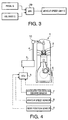
- FIG. 3 is a block-diagram illustrating vehicle speed limit computation means of the preferred embodiment of the fuel injection quantity control device in accordance with the present invention.
- FIG. 4 is a system diagram illustrating the preferred embodiment of the fuel injection quantity control device in accordance with the present invention.
- the fuel injection quantity control device of a diesel engine carried on a vehicle with a manual transmission will be considered as an example.
- a diesel engine 1 is provided with a fuel injection nozzle 2 for injecting fuel.
- Fuel is pumped into the fuel injection nozzle 2 from a fuel injection pump 3 via a fuel pipe 4 and a common rail 10.
- the common rail 10 is connected to the fuel pipe 4 located upstream thereof and to fuel injection nozzles 2 located downstream thereof, thereby branching the fuel from the fuel injection pump 3 into the fuel injection nozzles 2.
- the fuel injection pump 3 is herein a distribution-type pump and the fuel pumping quantity thereof is controlled with an electronic control unit (referred to as ECU hereinbelow) 5.
- ECU electronice control unit
- the fuel injection pump 3 is provided with an electromagnetic valve for determining the fuel pumping quantity, and the ECU 5 controls the fuel pumping quantity by appropriately switching this electromagnetic valve.
- An engine revolution speed sensor 6 is connected to the ECU 5, and the ECU 5 detects the engine revolution speed based on the output of the sensor.
- the aforesaid ECU 5 and engine revolution speed sensor 6 constitute engine revolution detection means.
- An accelerator opening degree sensor 7 is connected to the ECU 5, and the ECU 5 detects the accelerator opening degree based on the output of the sensor.
- the aforesaid ECU 5 and accelerator opening degree sensor 7 constitute accelerator opening degree detection means.
- a vehicle speed sensor 8 is connected to the ECU 5, and the ECU 5 detects the vehicle speed based on the output of the sensor.
- the aforesaid ECU 5 and vehicle speed sensor 8 constitute vehicle speed detection means.
- a gear position sensor 9 is connected to the ECU 5, and the ECU 5 detects the present gear position based on the output of the sensor.
- the aforesaid ECU 5 and gear position sensor 9 constitute gear position detection means.
- the ECU 5 comprises target acceleration value computation means for deriving the basic target acceleration value corresponding to the difference between the aforesaid set limit vehicle speed and actual vehicle speed and the present gear position from a map, finding in a map the upper limit value and lower limit value of the basic target acceleration value for each gear position, limiting the basic target acceleration with the upper limit value and lower limit value and determining a target acceleration value, basic fuel injection quantity for vehicle speed limit computation means for determining a basic fuel injection quantity for vehicle speed limit by feedback computation from the difference between the target acceleration value determined with the aforesaid target acceleration value computation means and the actual acceleration value, accelerator required injection quantity computation means for computing the accelerator required injection quantity from the engine revolution speed and accelerator opening degree, and vehicle speed limit injection quantity computation means for selecting the smaller of the aforesaid basic fuel injection quantity for vehicle speed limit and accelerator required injection quantity and selecting it as the fuel injection quantity for vehicle speed limit that will be actually injected into the engine.
- Target acceleration value computation means basic fuel injection quantity for vehicle speed limit computation means, and vehicle speed limit injection quantity computation means will be described hereinbelow with reference to FIG. 1, FIG. 2, and FIG. 3, respectively. Calculations or decisions explained hereinbelow are made repeatedly by the ECU 5 for each prescribed interval based on the relationship for digital processing of each value.
- a difference (vcl sp err) is computed by subtracting the actual vehicle speed (Vehicle Speed) detected by vehicle speed detection means from a set limit vehicle speed (Vehicle Speed Limit) set in the ECU 5 in advance. This difference and gear position (Gear Position) are then inputted in a map M1.
- map M1 a target acceleration value corresponding to the difference (vcl sp err) and gear position (Gear Position) has been inputted in advance based on the test results, and the target acceleration value is uniquely found by inputting the difference and gear position into the map M1.
- the target acceleration value is found from the difference (vcl sp err) and gear position (Gear Position) in map M1, but the target acceleration value may be also found only from the difference (vcl sp err).
- a map M2 for determining the upper limit value of target acceleration value corresponding to the gear position and a map M3 for determining the lower limit value are provided in target acceleration value computation means.
- map M2 the upper limit value tends to decrease with increase in gear position.
- the lower limit value tends to increase with increase in gear position.
- the lower limit value assumes a negative value and the absolute value thereof decreases and approaches 0 as the gear position increases.
- a gear position (Gear Position) is inputted, the upper limit value and lower limit value are found, and those upper limit value and lower limit value are inputted into a limit unit 12.
- the basic target acceleration value inputted from the map M1 is compared with the upper limit value and lower limit value and a target acceleration value is determined. More specifically, when the inputted basic target acceleration value is larger than the upper limit value, the upper limit value is outputted as a target acceleration value (Vehicle Speed Target Acceleration), and when the inputted basic target acceleration value is less than the lower limit value, the lower limit value is outputted as a target acceleration value (Vehicle Speed Target Acceleration). Furthermore, when the inputted basic target acceleration value is between the lower limit value and upper limit value, this target acceleration value is outputted as is.
- the target acceleration value (Vehicle Speed Target Acceleration) found by this target acceleration value computation means is transmitted to basic fuel injection quantity for vehicle speed limit computation means of the next stage.
- the difference (vsl acc err) is computed by subtracting the actual acceleration value (Vehicle Acceleration) found from the change in the vehicle speed from the target acceleration value(VSL Target Acceleration) found by target acceleration value computation means.
- the difference (vsl acc err) and gear position (Gear Position) are then inputted in map M4 and map M5, respectively.
- a coefficient for the proportional term corresponding to the difference (vsl acc err) and gear position (Gear Position) has been inputted in advance based on the test results, and the coefficient which is to be multiplied by the difference is uniquely found by inputting the difference and gear position into the map M4.
- a coefficient for the integral term corresponding to the difference (vsl acc err) and gear position (Gear Position) has been inputted in advance based on the test results, and the coefficient which is to be multiplied by the difference is uniquely found by inputting the difference and gear position into the map M5.
- VSL Base Q This basic fuel injection quantity for vehicle speed limit (VSL Base Q) found with basic fuel injection quantity for vehicle speed limit computation means is transmitted to vehicle speed limit injection quantity computation means of the next stage.
- vehicle speed limit injection quantity computation means the basic fuel injection quantity for vehicle speed limit (VSL Base Q) found with basic fuel injection quantity for vehicle speed limit computation means and the accelerator required injection quantity (Pedal Q) are inputted in a comparator 19.
- the comparator 19 the smaller of them is selected as a vehicle speed limit injection quantity (Vehicle Speed Limit Q).
- accelerator required injection quantity computation means computes the accelerator required injection quantity by inputting the engine revolution speed detected by engine revolution speed detection means and the accelerator opening degree detected by accelerator opening degree detection means into a map (not shown in the figures).
- the accelerator required injection quantity usually tends to decrease with the increase in the engine revolution speed and to increase with the increase in the accelerator opening degree.
- This vehicle speed limit injection quantity found with vehicle speed limit injection quantity computation means serves as the fuel injection quantity that will be actually injected into the engine.
- the optimum fuel injection quantity is determined for each gear position by deriving the basic target acceleration value corresponding to the difference (vsl sp err) between the set limit vehicle speed (Vehicle Speed Limit) and actual vehicle speed (Vehicle Speed), and the present gear position (Gear Position) from the map M1, finding the upper limit value and the lower limit value of the basic target acceleration value for each gear position in the maps M2 and M3, limiting the aforesaid basic target acceleration value with the upper limit value and the lower limit value, and determining a target acceleration value (VSL Target Acceleration). Therefore, since the optimum fuel injection is determined in response to each gear position, overshoot can be reliably prevented for any gear position.
- the optimum fuel injection quantity is determined according to the gear position during vehicle speed limit control. Therefore, the present invention demonstrates an excellent effect of reliably preventing the overshoot.
Landscapes
- Engineering & Computer Science (AREA)
- Mechanical Engineering (AREA)
- Chemical & Material Sciences (AREA)
- Combustion & Propulsion (AREA)
- General Engineering & Computer Science (AREA)
- Transportation (AREA)
- Automation & Control Theory (AREA)
- Electrical Control Of Air Or Fuel Supplied To Internal-Combustion Engine (AREA)
- Control Of Vehicle Engines Or Engines For Specific Uses (AREA)
- Combined Controls Of Internal Combustion Engines (AREA)
Abstract
The optimum fuel injection quantity is determined for each gear position by deriving the basic target acceleration value corresponding to the difference between the set limit vehicle speed and the actual vehicle speed from a map, finding the upper limit value and the lower limit value of the basic target acceleration value for each gear position in the map.
Description
Claims (6)
- A fuel injection quantity control device for limiting a fuel injection quantity so as to prevent vehicle speed from exceeding a set limit vehicle speed, this device comprising:vehicle speed detection means for detecting the vehicle speed;gear position detection means for detecting a gear position;engine revolution speed detection means for detecting an engine revolution speed;accelerator opening degree detection means for detecting an accelerator opening degree;target acceleration value computation means for deriving a basic target acceleration value corresponding to the difference between the set limit vehicle speed and an actual vehicle speed from a map, finding in a map an upper limit value and lower limit value of the basic target acceleration value for each gear position, limiting the basic target acceleration value with the upper limit value and lower limit value, and determining a target acceleration value;basic fuel injection quantity for vehicle speed limit computation means for determining a basic fuel injection quantity for vehicle speed limit by feedback computation from the difference between the target acceleration value determined with the target acceleration value computation means and the actual acceleration value;accelerator required injection quantity computation means for computing an accelerator required injection quantity from the engine revolution speed and accelerator opening degree; andvehicle speed limit injection quantity computation means for selecting the smaller of the basic fuel injection quantity for the vehicle speed limit and the accelerator required injection quantity and setting it as a fuel injection quantity for vehicle speed limit that will be actually injected into the engine.
- The fuel injection quantity control device according to claim 1, characterized in that the target acceleration value computation means derives the basic target acceleration from the map in which a gear position also serves as a parameter in addition to the difference between the set limit vehicle speed and actual vehicle speed.
- The fuel injection quantity control device according to claim 1 or 2, characterized in that the basic fuel injection quantity for vehicle speed limit computation means finds a proportional term and an integral term corresponding to the difference between the target acceleration value and actual acceleration value and the gear position and obtains the basic fuel injection quantity for vehicle speed limit by adding up the proportional term and integral term.
- The fuel injection quantity control device according to claim 3, characterized in that the basic fuel injection quantity for vehicle speed limit computation means finds from the map a coefficient for a proportional term corresponding to the difference between the target acceleration value and actual acceleration value and the gear position and obtains the proportional term by multiplying this coefficient for the proportional term by the difference.
- The fuel injection quantity control device according to claim 3 or 4, characterized in that the basic fuel injection quantity for vehicle speed limit computation means finds from the map a coefficient for an integral term corresponding to the difference between the target acceleration value and actual acceleration value and the gear position and obtains the integral term by multiplying this coefficient for the integral term by the difference and adding up an old value to the obtained value.
- The fuel injection quantity control device according to claim 1 or 2, characterized in that the accelerator required injection quantity computation means computes the accelerator required injection quantity by inputting the engine revolution speed and the accelerator opening degree into the map.
Applications Claiming Priority (2)
| Application Number | Priority Date | Filing Date | Title |
|---|---|---|---|
| JP2003020286A JP4039257B2 (en) | 2003-01-29 | 2003-01-29 | Fuel injection amount control device |
| JP2003020286 | 2003-01-29 |
Publications (2)
| Publication Number | Publication Date |
|---|---|
| EP1443193A1 true EP1443193A1 (en) | 2004-08-04 |
| EP1443193B1 EP1443193B1 (en) | 2006-11-08 |
Family
ID=32652869
Family Applications (1)
| Application Number | Title | Priority Date | Filing Date |
|---|---|---|---|
| EP04001266A Expired - Lifetime EP1443193B1 (en) | 2003-01-29 | 2004-01-21 | Fuel injection quantity control device |
Country Status (5)
| Country | Link |
|---|---|
| US (1) | US6934620B2 (en) |
| EP (1) | EP1443193B1 (en) |
| JP (1) | JP4039257B2 (en) |
| CN (1) | CN100370127C (en) |
| DE (1) | DE602004003074T2 (en) |
Cited By (3)
| Publication number | Priority date | Publication date | Assignee | Title |
|---|---|---|---|---|
| WO2011076373A1 (en) * | 2009-12-22 | 2011-06-30 | Volvo Lastvagnar Ab | A method for controlling vehicle acceleration |
| US10174839B2 (en) | 2015-02-20 | 2019-01-08 | Ford Global Technologies, Llc | Method for reducing the amount of fuel used by an engine of a motor vehicle |
| US20220316415A1 (en) * | 2021-03-30 | 2022-10-06 | Mazda Motor Corporation | Vehicle control system |
Families Citing this family (12)
| Publication number | Priority date | Publication date | Assignee | Title |
|---|---|---|---|---|
| JP5026188B2 (en) * | 2007-08-10 | 2012-09-12 | 株式会社デンソー | Vehicle control device and vehicle control system |
| JP5182157B2 (en) * | 2009-03-04 | 2013-04-10 | 日産自動車株式会社 | Diesel engine control device |
| JP5540686B2 (en) * | 2009-12-17 | 2014-07-02 | トヨタ自動車株式会社 | Vehicle control system |
| JP5780837B2 (en) * | 2011-06-01 | 2015-09-16 | 日野自動車株式会社 | VEHICLE CONTROL DEVICE, VEHICLE, VEHICLE CONTROL METHOD, AND PROGRAM |
| CN103423006B (en) * | 2012-05-22 | 2015-10-28 | 广西玉柴机器股份有限公司 | Mechanical fuel pump diesel highest speed restricting means |
| US10570839B2 (en) * | 2012-11-29 | 2020-02-25 | Ford Global Technologies, Llc | System and method for improving vehicle performance |
| JP6286965B2 (en) * | 2013-09-18 | 2018-03-07 | 株式会社豊田自動織機 | Vehicle speed control device for industrial vehicles |
| JP2016094883A (en) * | 2014-11-14 | 2016-05-26 | 株式会社豊田自動織機 | Fuel injection control device |
| JP6459450B2 (en) * | 2014-12-02 | 2019-01-30 | 三菱自動車工業株式会社 | Engine control device |
| CN112793418B (en) * | 2021-01-29 | 2022-07-15 | 广西玉柴机器股份有限公司 | Method and device for limiting vehicle speed based on acceleration principle |
| JP7694105B2 (en) * | 2021-03-30 | 2025-06-18 | マツダ株式会社 | Vehicle Control Systems |
| CN116480472B (en) * | 2023-05-17 | 2025-09-19 | 潍柴动力股份有限公司 | Supercharger rotation speed control method and device, electronic equipment and storage medium |
Citations (3)
| Publication number | Priority date | Publication date | Assignee | Title |
|---|---|---|---|---|
| US5665026A (en) * | 1995-03-16 | 1997-09-09 | Mercedes-Benz Ag | Method and apparatus for limiting the speed of a motor vehicle |
| JPH10250408A (en) | 1997-03-11 | 1998-09-22 | Honda Motor Co Ltd | Control method of constant speed traveling device for vehicle |
| US6135918A (en) * | 1998-06-18 | 2000-10-24 | Cummins Engine Company, Inc. | System for controlling operation of an internal combustion engine |
Family Cites Families (8)
| Publication number | Priority date | Publication date | Assignee | Title |
|---|---|---|---|---|
| GB1466867A (en) * | 1973-04-14 | 1977-03-09 | Cav Ltd | Control system for vehicles |
| JPS61196831A (en) * | 1985-02-26 | 1986-09-01 | Diesel Kiki Co Ltd | Automatic starting controller for internal-combustion engine vehicles |
| JPH02233854A (en) | 1989-03-06 | 1990-09-17 | Isuzu Motors Ltd | Vehicle acceleration controller |
| JPH0867171A (en) | 1994-08-29 | 1996-03-12 | Nippondenso Co Ltd | Constant speed running control device for vehicle |
| JPH10252520A (en) | 1997-03-14 | 1998-09-22 | Nissan Diesel Motor Co Ltd | Car speed limit device |
| FR2766874B1 (en) * | 1997-08-01 | 1999-10-15 | Renault Agriculture | METHOD FOR CONTROLLING AN INTERNAL COMBUSTION ENGINE |
| JP3588999B2 (en) * | 1997-12-15 | 2004-11-17 | 日産自動車株式会社 | Control device during cold / warm-up of diesel engine |
| JP3991600B2 (en) * | 2001-03-01 | 2007-10-17 | 日産自動車株式会社 | Fuel injection amount control device for diesel engine |
-
2003
- 2003-01-29 JP JP2003020286A patent/JP4039257B2/en not_active Expired - Fee Related
-
2004
- 2004-01-21 EP EP04001266A patent/EP1443193B1/en not_active Expired - Lifetime
- 2004-01-21 DE DE602004003074T patent/DE602004003074T2/en not_active Expired - Lifetime
- 2004-01-26 US US10/764,912 patent/US6934620B2/en not_active Expired - Lifetime
- 2004-01-29 CN CNB2004100035365A patent/CN100370127C/en not_active Expired - Lifetime
Patent Citations (3)
| Publication number | Priority date | Publication date | Assignee | Title |
|---|---|---|---|---|
| US5665026A (en) * | 1995-03-16 | 1997-09-09 | Mercedes-Benz Ag | Method and apparatus for limiting the speed of a motor vehicle |
| JPH10250408A (en) | 1997-03-11 | 1998-09-22 | Honda Motor Co Ltd | Control method of constant speed traveling device for vehicle |
| US6135918A (en) * | 1998-06-18 | 2000-10-24 | Cummins Engine Company, Inc. | System for controlling operation of an internal combustion engine |
Non-Patent Citations (1)
| Title |
|---|
| PATENT ABSTRACTS OF JAPAN vol. 1998, no. 14 31 December 1998 (1998-12-31) * |
Cited By (4)
| Publication number | Priority date | Publication date | Assignee | Title |
|---|---|---|---|---|
| WO2011076373A1 (en) * | 2009-12-22 | 2011-06-30 | Volvo Lastvagnar Ab | A method for controlling vehicle acceleration |
| US10174839B2 (en) | 2015-02-20 | 2019-01-08 | Ford Global Technologies, Llc | Method for reducing the amount of fuel used by an engine of a motor vehicle |
| US20220316415A1 (en) * | 2021-03-30 | 2022-10-06 | Mazda Motor Corporation | Vehicle control system |
| US11852090B2 (en) * | 2021-03-30 | 2023-12-26 | Mazda Motor Corporation | Vehicle control system |
Also Published As
| Publication number | Publication date |
|---|---|
| CN100370127C (en) | 2008-02-20 |
| DE602004003074T2 (en) | 2007-04-05 |
| JP2004232516A (en) | 2004-08-19 |
| DE602004003074D1 (en) | 2006-12-21 |
| US6934620B2 (en) | 2005-08-23 |
| US20040158385A1 (en) | 2004-08-12 |
| JP4039257B2 (en) | 2008-01-30 |
| CN1532393A (en) | 2004-09-29 |
| EP1443193B1 (en) | 2006-11-08 |
Similar Documents
| Publication | Publication Date | Title |
|---|---|---|
| EP1443193B1 (en) | Fuel injection quantity control device | |
| US6581574B1 (en) | Method for controlling fuel rail pressure | |
| US6480782B2 (en) | System for managing charge flow and EGR fraction in an internal combustion engine | |
| US5806497A (en) | Method of and apparatus for controlling fuel injection of internal combustion engine | |
| US4727838A (en) | Apparatus for controlling internal combustion engine | |
| US9255529B2 (en) | Longitudinal G adjusted throttle response | |
| EP0924421A2 (en) | A fuel injection control device for an internal combustion engine | |
| US6983735B2 (en) | Control apparatus for controlling the amount of intake air into an engine | |
| US6578546B2 (en) | Method and device for controlling an internal combustion engine | |
| US5445124A (en) | Method and apparatus for controlling the idle speed of an internal combustion engine | |
| JP5482532B2 (en) | Fuel injection control device | |
| US7096111B2 (en) | Method for converting a fuel quantity into a torque | |
| JPH09105352A (en) | Internal combustion engine control method and apparatus | |
| US20040079329A1 (en) | Method of controlling the rotational speed of a drive unit | |
| EP0740061B1 (en) | Electronic fuel injection control system and control method | |
| US20050279324A1 (en) | Method for conrolling an internal combustion engine generator unit | |
| US6886531B1 (en) | Control apparatus for an internal combustion engine | |
| JP4192615B2 (en) | Fuel injection amount control device | |
| US8381703B2 (en) | Method for calibrating an accelerator pedal | |
| JP2007146657A (en) | Fuel injection control device | |
| JP4475212B2 (en) | Fuel injection control device | |
| US6442471B1 (en) | Drive train control of a vehicle having continuously variable transmission | |
| US9194324B2 (en) | Internal combustion engine control methods | |
| KR100405720B1 (en) | Fuel injection control method for engine | |
| JP2005214060A (en) | Vehicle speed control device |
Legal Events
| Date | Code | Title | Description |
|---|---|---|---|
| PUAI | Public reference made under article 153(3) epc to a published international application that has entered the european phase |
Free format text: ORIGINAL CODE: 0009012 |
|
| AK | Designated contracting states |
Kind code of ref document: A1 Designated state(s): AT BE BG CH CY CZ DE DK EE ES FI FR GB GR HU IE IT LI LU MC NL PT RO SE SI SK TR |
|
| AX | Request for extension of the european patent |
Extension state: AL LT LV MK |
|
| 17P | Request for examination filed |
Effective date: 20041105 |
|
| AKX | Designation fees paid |
Designated state(s): DE FR GB IT |
|
| 17Q | First examination report despatched |
Effective date: 20050318 |
|
| GRAP | Despatch of communication of intention to grant a patent |
Free format text: ORIGINAL CODE: EPIDOSNIGR1 |
|
| GRAS | Grant fee paid |
Free format text: ORIGINAL CODE: EPIDOSNIGR3 |
|
| GRAA | (expected) grant |
Free format text: ORIGINAL CODE: 0009210 |
|
| AK | Designated contracting states |
Kind code of ref document: B1 Designated state(s): DE FR GB IT |
|
| REG | Reference to a national code |
Ref country code: GB Ref legal event code: FG4D |
|
| REF | Corresponds to: |
Ref document number: 602004003074 Country of ref document: DE Date of ref document: 20061221 Kind code of ref document: P |
|
| ET | Fr: translation filed | ||
| PLBE | No opposition filed within time limit |
Free format text: ORIGINAL CODE: 0009261 |
|
| STAA | Information on the status of an ep patent application or granted ep patent |
Free format text: STATUS: NO OPPOSITION FILED WITHIN TIME LIMIT |
|
| 26N | No opposition filed |
Effective date: 20070809 |
|
| PGFP | Annual fee paid to national office [announced via postgrant information from national office to epo] |
Ref country code: IT Payment date: 20100118 Year of fee payment: 7 |
|
| PG25 | Lapsed in a contracting state [announced via postgrant information from national office to epo] |
Ref country code: IT Free format text: LAPSE BECAUSE OF NON-PAYMENT OF DUE FEES Effective date: 20110121 |
|
| REG | Reference to a national code |
Ref country code: FR Ref legal event code: PLFP Year of fee payment: 12 |
|
| REG | Reference to a national code |
Ref country code: DE Ref legal event code: R082 Ref document number: 602004003074 Country of ref document: DE Representative=s name: SCHAUMBURG UND PARTNER PATENTANWAELTE MBB, DE Ref country code: DE Ref legal event code: R082 Ref document number: 602004003074 Country of ref document: DE Representative=s name: SCHAUMBURG & PARTNER PATENTANWAELTE GBR, DE Ref country code: DE Ref legal event code: R082 Ref document number: 602004003074 Country of ref document: DE Representative=s name: SCHAUMBURG & PARTNER PATENTANWAELTE MBB, DE |
|
| PGFP | Annual fee paid to national office [announced via postgrant information from national office to epo] |
Ref country code: FR Payment date: 20150108 Year of fee payment: 12 Ref country code: GB Payment date: 20150121 Year of fee payment: 12 |
|
| GBPC | Gb: european patent ceased through non-payment of renewal fee |
Effective date: 20160121 |
|
| REG | Reference to a national code |
Ref country code: FR Ref legal event code: ST Effective date: 20160930 |
|
| PG25 | Lapsed in a contracting state [announced via postgrant information from national office to epo] |
Ref country code: GB Free format text: LAPSE BECAUSE OF NON-PAYMENT OF DUE FEES Effective date: 20160121 |
|
| PG25 | Lapsed in a contracting state [announced via postgrant information from national office to epo] |
Ref country code: FR Free format text: LAPSE BECAUSE OF NON-PAYMENT OF DUE FEES Effective date: 20160201 |
|
| PGFP | Annual fee paid to national office [announced via postgrant information from national office to epo] |
Ref country code: DE Payment date: 20221130 Year of fee payment: 20 |
|
| REG | Reference to a national code |
Ref country code: DE Ref legal event code: R071 Ref document number: 602004003074 Country of ref document: DE |