EP1442945A1 - Fahrergassackmodul - Google Patents
Fahrergassackmodul Download PDFInfo
- Publication number
- EP1442945A1 EP1442945A1 EP04001190A EP04001190A EP1442945A1 EP 1442945 A1 EP1442945 A1 EP 1442945A1 EP 04001190 A EP04001190 A EP 04001190A EP 04001190 A EP04001190 A EP 04001190A EP 1442945 A1 EP1442945 A1 EP 1442945A1
- Authority
- EP
- European Patent Office
- Prior art keywords
- gas bag
- driver
- bag module
- outer edge
- center
- Prior art date
- Legal status (The legal status is an assumption and is not a legal conclusion. Google has not performed a legal analysis and makes no representation as to the accuracy of the status listed.)
- Granted
Links
Images
Classifications
-
- B—PERFORMING OPERATIONS; TRANSPORTING
- B60—VEHICLES IN GENERAL
- B60R—VEHICLES, VEHICLE FITTINGS, OR VEHICLE PARTS, NOT OTHERWISE PROVIDED FOR
- B60R21/00—Arrangements or fittings on vehicles for protecting or preventing injuries to occupants or pedestrians in case of accidents or other traffic risks
- B60R21/02—Occupant safety arrangements or fittings, e.g. crash pads
- B60R21/16—Inflatable occupant restraints or confinements designed to inflate upon impact or impending impact, e.g. air bags
- B60R21/23—Inflatable members
- B60R21/231—Inflatable members characterised by their shape, construction or spatial configuration
Definitions
- the invention relates to a driver gas bag module, with a gas bag that has a based on the inflated condition, has front wall facing the driver is facing and the central portion in the inflated state Has indentation by the middle section at least partially on a Movement in the direction out of the gas bag module is prevented.
- the gas bag is usually ring-shaped.
- the front wall is there the wall of the gas bag that faces the driver when inflated and that the driver can hit.
- the middle section is usually that Center of the front wall, at least at the beginning of the deployment on the gas bag module remains attached, so that the already mentioned in the inflated state Ring shape of the gas bag forms. Due to this ring shape, the gas bag is at an angle outwards from the module housed in the steering wheel of the vehicle then the front wall moves towards the driver.
- the invention creates a simple and inexpensive to manufacture Driver gas bag module, which also under non-optimal deployment conditions improved protection for the driver is achieved.
- the input is mentioned type provided that the front wall, based on the center of the Indentation has an upper and a lower area, the outer edge of the upper region has three substantially straight sections.
- the invention sees an "angular" contour of the upper region the front wall of the gas bag in front, which supports the gas bag on the rim of the steering wheel of the vehicle during deployment. Because of the special Geometry of the upper area thus becomes one under unfavorable conditions possible immersion of the gas bag behind the steering wheel rim during the Unfolding is avoided without pre-folding the gas bag. The elimination of prefolding generally leads to greater process reliability in the manufacture of the gas bag module. In addition, the cycle time in the folding process of the gas bag can be shortened.
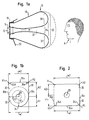
- the gas bag module 10 shown in FIG. 1a is in the steering wheel of a vehicle accommodated.
- the gas bag module 10 has a gas generator 12 around which around a holding part in the form of a diffuser 14 is arranged.
- the diffuser 14 is again together with the gas generator 12 on the housing 16 of the gas bag module 10 locked.
- Between the diffuser 14 and the outer wall of the housing an annular space is formed in which a gas bag folded without pre-folding 18 is housed.
- a cover flap 20 closes the gas bag module 10 in unfolded state of the gas bag 18 and is unfolded to the outside pivoted.
- the gas bag 18 consists of a gas bag wall that has several sections, including a section called front wall 22.
- the Front wall 22 is the part of the gas bag 18 which faces driver A.
- the Front wall 22 has a central section, in the following central section 24 called, which runs in the direction of the diffuser 14, that is, inside the Gas bags 18 is directed so that there is an indentation 26.
- the top view of the gas bag module 10 shown in FIG. 1b shows the shape of the gas bag 18 from the driver's point of view A.
- the front wall 22 can be in an area above the center 28 of the indentation 26 (upper area 30) and divide an area below the center 28 (lower area 32), the lower region 32 being shaped differently from the upper region 30.
- the lower region 32 essentially has the shape of a ring section with a has round outer edge 34
- the outer edge 36 of the upper region 30 has three in substantially straight, through two curved transition sections 36d, 36e connected sections 36a, 36b, 36c.
- the radii R1, R2 of the curved Transition sections 36d, 36e are significantly smaller than the radii R3, R4 determine the curvature of the outer edge 34 of the lower region 32, and thus significantly smaller than the distance between the curved transition sections 36d, 36e from the center 28 of the indentation 26. This gives the upper region 30 the Front wall 22 has a comparatively "angular" shape.
- the horizontal width w1 (transverse to the vehicle longitudinal direction) of the lower area 32 is equal to the width w2 of the upper region 30, and the vertical height h1 of the lower region 32 is smaller than the height h2 of upper region 30.
- the width w2 of the upper region can be larger than the width w1 of the lower area and / or the heights h1, h2 of the two Areas 30, 32 are the same.
- the embodiment shown in Figure 2 differs from that previously Embodiment described in that the lower region 32 a "angular" shape, so that there is an overall rectangular shape of the front wall 22 results.
- the outer edge 34 of the lower region 32 can be analogous to The outer edge 36 of the upper region 30 in three substantially straight sections 34a, 34b, 34c and two curved transition sections 34d, 34e with radii of curvature Subdivide R3 or R4.
- Both embodiments shown have in common that in particular the “Angular” upper region 30 of the front wall 22 supports the gas bag 18 on the steering wheel rim supports the unfolding and thus plunges behind prevents the steering wheel rim.
Landscapes
- Engineering & Computer Science (AREA)
- Mechanical Engineering (AREA)
- Air Bags (AREA)
Abstract
Description
- Figur 1a eine Seitenansicht eines erfindungsgemäßen Fahrergassackmoduls mit aufgeblasenem Gassack gemäß einer ersten Ausführungsform;
- Figur 1b eine Draufsicht auf das Fahrergassackmodul aus Figur 1a; und
- Figur 2 eine Draufsicht auf ein erfindungsgemäßes Fahrergassackmodul mit aufgeblasenem Gassack gemäß einer zweiten Ausführungsform.
Claims (7)
- Fahrergassackmodul, mit einem Gassack (18), der eine, bezogen auf den aufgeblasenen Zustand, Vorderwand (22) aufweist, die dem Fahrer (A) zugewandt ist und deren Mittenabschnitt (24) im aufgeblasenen Zustand eine Einbuchtung (26) aufweist, indem der Mittenabschnitt (24) wenigstens teilweise an einer Bewegung in Richtung aus dem Gassackmodul (10) heraus gehindert wird, dadurch gekennzeichnet, daß die Vorderwand (22), bezogen auf das Zentrum (28) der Einbuchtung (26), einen oberen Bereich (30) und einen unteren Bereich (32) aufweist, wobei der Außenrand (36) des oberen Bereichs (30) drei im wesentlichen gerade Abschnitte (36a, 36b, 36c) aufweist.
- Fahrergassackmodul nach Anspruch 1, dadurch gekennzeichnet, daß die drei geraden Abschnitte (36a, 36b, 36c) des Außenrands (36) des oberen Bereichs (30) durch gekrümmte Übergangsabschnitte (36d, 36e) miteinander verbunden sind, deren Radien (R1, R2) wesentlich kleiner sind als ihr Abstand vom Zentrum (28) der Einbuchtung (26).
- Fahrergassackmodul nach Anspruch 1 oder 2, dadurch gekennzeichnet, daß die horizontale Breite (w2) des oberen Bereichs (30) größer oder gleich der horizontalen Breite (w1) des unteren Bereichs (32) ist.
- Fahrergassackmodul nach einem der vorhergehenden Ansprüche, dadurch gekennzeichnet, daß die vertikale Höhe (h2) des oberen Bereichs (30) größer oder gleich der vertikalen Höhe (h1) des unteren Bereichs (32) ist.
- Fahrergassackmodul nach einem der vorhergehenden Ansprüche, dadurch gekennzeichnet, daß der Außenrand (34) des unteren Bereichs (32) eine kontinuierliche Krümmung aufweist, die durch wenigstens einen Radius (R3, R4) definiert ist, der im wesentlichen dem Abstand des Außenrands (34) vom Zentrum (28) der Einbuchtung (26) entspricht.
- Fahrergassackmodul nach einem der Ansprüche 1 bis 4, dadurch gekennzeichnet, daß auch der Außenrand (34) des unteren Bereichs (32) drei im wesentlichen gerade Abschnitte (34a, 34b, 34c) aufweist.
- Fahrergassackmodul nach Anspruch 6, dadurch gekennzeichnet, daß die drei geraden Abschnitte (34a, 34b, 34c) des unteren Bereichs (32) durch gekrümmte Übergangsabschnitte (34d, 34e) miteinander verbunden sind, deren Radien (R3, R4) wesentlich kleiner sind als ihr Abstand vom Zentrum (28) der Einbuchtung (26).
Applications Claiming Priority (2)
| Application Number | Priority Date | Filing Date | Title |
|---|---|---|---|
| DE20301521U | 2003-01-31 | ||
| DE20301521U DE20301521U1 (de) | 2003-01-31 | 2003-01-31 | Fahrergassackmodul |
Publications (2)
| Publication Number | Publication Date |
|---|---|
| EP1442945A1 true EP1442945A1 (de) | 2004-08-04 |
| EP1442945B1 EP1442945B1 (de) | 2005-12-14 |
Family
ID=7979610
Family Applications (1)
| Application Number | Title | Priority Date | Filing Date |
|---|---|---|---|
| EP04001190A Expired - Lifetime EP1442945B1 (de) | 2003-01-31 | 2004-01-21 | Fahrergassackmodul |
Country Status (4)
| Country | Link |
|---|---|
| US (1) | US20040183288A1 (de) |
| EP (1) | EP1442945B1 (de) |
| DE (2) | DE20301521U1 (de) |
| ES (1) | ES2254995T3 (de) |
Families Citing this family (4)
| Publication number | Priority date | Publication date | Assignee | Title |
|---|---|---|---|---|
| JP4235975B2 (ja) * | 2005-06-10 | 2009-03-11 | オートリブ ディベロップメント エービー | エアバッグ装置及び、エアバッグの製造方法 |
| US7360795B2 (en) * | 2005-07-28 | 2008-04-22 | Autoliv Asp, Inc. | Torsion bar load limiter and pretensioner for seat belt system |
| KR20090126087A (ko) * | 2008-06-03 | 2009-12-08 | 현대자동차주식회사 | 차량용 에어백 장치 |
| JP6070646B2 (ja) * | 2014-07-08 | 2017-02-01 | マツダ株式会社 | エアバッグ装置 |
Citations (2)
| Publication number | Priority date | Publication date | Assignee | Title |
|---|---|---|---|---|
| DE19816080A1 (de) * | 1998-04-09 | 1999-10-14 | Volkswagen Ag | Sicherheitsvorrichtung für ein Kraftfahrzeug mit einem Airbag, insbesondere einem Beifahrerairbag |
| DE19860804A1 (de) * | 1998-12-30 | 2000-07-06 | Volkswagen Ag | Anordnung eines Fahrerairbags in einem Kraftfahrzeug |
Family Cites Families (5)
| Publication number | Priority date | Publication date | Assignee | Title |
|---|---|---|---|---|
| JPH03186448A (ja) * | 1989-12-15 | 1991-08-14 | Takata Kk | パッセンジャー用エアバッグ |
| US6494484B2 (en) * | 1999-04-23 | 2002-12-17 | Milliken & Company | Polygon-shaped air bag |
| JP4608072B2 (ja) * | 2000-02-25 | 2011-01-05 | タカタ株式会社 | エアバッグ装置 |
| DE10065463C2 (de) * | 2000-05-19 | 2003-12-18 | Trw Automotive Safety Sys Gmbh | Airbagmodul |
| JP2003160016A (ja) * | 2001-11-22 | 2003-06-03 | Takata Corp | 助手席用エアバッグ装置 |
-
2003
- 2003-01-31 DE DE20301521U patent/DE20301521U1/de not_active Expired - Lifetime
-
2004
- 2004-01-21 EP EP04001190A patent/EP1442945B1/de not_active Expired - Lifetime
- 2004-01-21 ES ES04001190T patent/ES2254995T3/es not_active Expired - Lifetime
- 2004-01-21 DE DE502004000174T patent/DE502004000174D1/de not_active Expired - Fee Related
- 2004-01-29 US US10/767,634 patent/US20040183288A1/en not_active Abandoned
Patent Citations (2)
| Publication number | Priority date | Publication date | Assignee | Title |
|---|---|---|---|---|
| DE19816080A1 (de) * | 1998-04-09 | 1999-10-14 | Volkswagen Ag | Sicherheitsvorrichtung für ein Kraftfahrzeug mit einem Airbag, insbesondere einem Beifahrerairbag |
| DE19860804A1 (de) * | 1998-12-30 | 2000-07-06 | Volkswagen Ag | Anordnung eines Fahrerairbags in einem Kraftfahrzeug |
Also Published As
| Publication number | Publication date |
|---|---|
| US20040183288A1 (en) | 2004-09-23 |
| DE502004000174D1 (de) | 2006-01-19 |
| DE20301521U1 (de) | 2003-06-26 |
| ES2254995T3 (es) | 2006-06-16 |
| EP1442945B1 (de) | 2005-12-14 |
Similar Documents
| Publication | Publication Date | Title |
|---|---|---|
| DE68909027T2 (de) | Airbagmodul und sein Herstellungsverfahren. | |
| EP0999101B1 (de) | Gassack-Seitenaufprall-Schutzeinrichtung | |
| EP0995642B1 (de) | Gassack für ein Fahrzeuginsassen- Rückhaltesystem | |
| DE60018158T2 (de) | Seitenairbagsystem und dessen Herstellungsverfahren | |
| DE3544248C1 (de) | Aufblasbares Aufprallschutzkissen | |
| EP0714818B1 (de) | Seitenaufprall-Gassack | |
| DE19858690A1 (de) | Luftsack | |
| EP1231115B1 (de) | Gassack-Modul | |
| DE69803370T2 (de) | Luftsack | |
| EP2695777B1 (de) | Gassack für ein Fahrzeuginsassen-Rückhaltesystem und Verfahren zum Herstellen eines Fahrzeuginsassen-Rückhaltesystems | |
| EP0936981B1 (de) | Gassack für ein airbagmodul sowie verfahren und vorrichtung zur faltung eines gassacks | |
| WO2015124164A1 (de) | Seitenairbag für fahrzeuge | |
| EP1062126B1 (de) | Airbagmodul, insbesondere beifahrerairbagmodul | |
| EP0861760B1 (de) | Flexibler Airbag-Behälter | |
| EP1442945A1 (de) | Fahrergassackmodul | |
| EP1467898A1 (de) | Airbagmodul für kraftfahrzeuge | |
| DE102020134796B4 (de) | Airbagkissen für ein Fahrzeug | |
| DE102004006317B4 (de) | Gassack und Gssackmodul | |
| DE10246769A1 (de) | Seitenaufprall-Schutzvorrichtung | |
| DE102023132907A1 (de) | Luftsack, vorzugsweise OPW-Luftsack, für ein Fahrzeug | |
| DE102017102049A1 (de) | Gasgeneratorhalter und Gassackmodul | |
| DE10204486A1 (de) | Schutzeinrichtung für Insasssen von Kraftfahrzeugen | |
| DE19837897B4 (de) | Aufblasbarer Luftsack für Kraftfahrzeuge | |
| EP1738968B1 (de) | Gassack | |
| EP0714814A1 (de) | Airbag-Modul |
Legal Events
| Date | Code | Title | Description |
|---|---|---|---|
| PUAI | Public reference made under article 153(3) epc to a published international application that has entered the european phase |
Free format text: ORIGINAL CODE: 0009012 |
|
| AK | Designated contracting states |
Kind code of ref document: A1 Designated state(s): AT BE BG CH CY CZ DE DK EE ES FI FR GB GR HU IE IT LI LU MC NL PT RO SE SI SK TR |
|
| AX | Request for extension of the european patent |
Extension state: AL LT LV MK |
|
| 17P | Request for examination filed |
Effective date: 20050125 |
|
| 17Q | First examination report despatched |
Effective date: 20050224 |
|
| AKX | Designation fees paid |
Designated state(s): DE ES FR GB IT |
|
| GRAP | Despatch of communication of intention to grant a patent |
Free format text: ORIGINAL CODE: EPIDOSNIGR1 |
|
| GRAS | Grant fee paid |
Free format text: ORIGINAL CODE: EPIDOSNIGR3 |
|
| GRAA | (expected) grant |
Free format text: ORIGINAL CODE: 0009210 |
|
| AK | Designated contracting states |
Kind code of ref document: B1 Designated state(s): DE ES FR GB IT |
|
| PG25 | Lapsed in a contracting state [announced via postgrant information from national office to epo] |
Ref country code: GB Free format text: LAPSE BECAUSE OF FAILURE TO SUBMIT A TRANSLATION OF THE DESCRIPTION OR TO PAY THE FEE WITHIN THE PRESCRIBED TIME-LIMIT Effective date: 20051214 |
|
| REG | Reference to a national code |
Ref country code: GB Ref legal event code: FG4D Free format text: NOT ENGLISH |
|
| PGFP | Annual fee paid to national office [announced via postgrant information from national office to epo] |
Ref country code: FR Payment date: 20060104 Year of fee payment: 3 |
|
| REF | Corresponds to: |
Ref document number: 502004000174 Country of ref document: DE Date of ref document: 20060119 Kind code of ref document: P |
|
| PGFP | Annual fee paid to national office [announced via postgrant information from national office to epo] |
Ref country code: ES Payment date: 20060120 Year of fee payment: 3 |
|
| PGFP | Annual fee paid to national office [announced via postgrant information from national office to epo] |
Ref country code: DE Payment date: 20060131 Year of fee payment: 3 |
|
| REG | Reference to a national code |
Ref country code: ES Ref legal event code: FG2A Ref document number: 2254995 Country of ref document: ES Kind code of ref document: T3 |
|
| GBV | Gb: ep patent (uk) treated as always having been void in accordance with gb section 77(7)/1977 [no translation filed] |
Effective date: 20051214 |
|
| ET | Fr: translation filed | ||
| PLBE | No opposition filed within time limit |
Free format text: ORIGINAL CODE: 0009261 |
|
| STAA | Information on the status of an ep patent application or granted ep patent |
Free format text: STATUS: NO OPPOSITION FILED WITHIN TIME LIMIT |
|
| 26N | No opposition filed |
Effective date: 20060915 |
|
| PG25 | Lapsed in a contracting state [announced via postgrant information from national office to epo] |
Ref country code: DE Free format text: LAPSE BECAUSE OF NON-PAYMENT OF DUE FEES Effective date: 20070801 |
|
| REG | Reference to a national code |
Ref country code: FR Ref legal event code: ST Effective date: 20070930 |
|
| REG | Reference to a national code |
Ref country code: ES Ref legal event code: FD2A Effective date: 20070122 |
|
| PG25 | Lapsed in a contracting state [announced via postgrant information from national office to epo] |
Ref country code: FR Free format text: LAPSE BECAUSE OF NON-PAYMENT OF DUE FEES Effective date: 20070131 |
|
| PG25 | Lapsed in a contracting state [announced via postgrant information from national office to epo] |
Ref country code: ES Free format text: LAPSE BECAUSE OF NON-PAYMENT OF DUE FEES Effective date: 20070122 |
|
| PG25 | Lapsed in a contracting state [announced via postgrant information from national office to epo] |
Ref country code: IT Free format text: LAPSE BECAUSE OF NON-PAYMENT OF DUE FEES Effective date: 20080121 |
|
| PGFP | Annual fee paid to national office [announced via postgrant information from national office to epo] |
Ref country code: IT Payment date: 20070131 Year of fee payment: 4 |