EP1442763A1 - Safety syringe with needle retracted by vacuum - Google Patents
Safety syringe with needle retracted by vacuum Download PDFInfo
- Publication number
- EP1442763A1 EP1442763A1 EP03250511A EP03250511A EP1442763A1 EP 1442763 A1 EP1442763 A1 EP 1442763A1 EP 03250511 A EP03250511 A EP 03250511A EP 03250511 A EP03250511 A EP 03250511A EP 1442763 A1 EP1442763 A1 EP 1442763A1
- Authority
- EP
- European Patent Office
- Prior art keywords
- holder
- plunger
- needle
- syringe barrel
- sealing member
- Prior art date
- Legal status (The legal status is an assumption and is not a legal conclusion. Google has not performed a legal analysis and makes no representation as to the accuracy of the status listed.)
- Withdrawn
Links
- 238000007789 sealing Methods 0.000 claims abstract description 50
- 125000006850 spacer group Chemical group 0.000 claims description 9
- 230000001360 synchronised effect Effects 0.000 claims description 3
- 239000007788 liquid Substances 0.000 description 3
- 239000008280 blood Substances 0.000 description 1
- 210000004369 blood Anatomy 0.000 description 1
Images


Classifications
-
- A—HUMAN NECESSITIES
- A61—MEDICAL OR VETERINARY SCIENCE; HYGIENE
- A61M—DEVICES FOR INTRODUCING MEDIA INTO, OR ONTO, THE BODY; DEVICES FOR TRANSDUCING BODY MEDIA OR FOR TAKING MEDIA FROM THE BODY; DEVICES FOR PRODUCING OR ENDING SLEEP OR STUPOR
- A61M5/00—Devices for bringing media into the body in a subcutaneous, intra-vascular or intramuscular way; Accessories therefor, e.g. filling or cleaning devices, arm-rests
- A61M5/178—Syringes
- A61M5/31—Details
- A61M5/32—Needles; Details of needles pertaining to their connection with syringe or hub; Accessories for bringing the needle into, or holding the needle on, the body; Devices for protection of needles
- A61M5/3205—Apparatus for removing or disposing of used needles or syringes, e.g. containers; Means for protection against accidental injuries from used needles
- A61M5/321—Means for protection against accidental injuries by used needles
- A61M5/322—Retractable needles, i.e. disconnected from and withdrawn into the syringe barrel by the piston
- A61M5/3234—Fully automatic needle retraction, i.e. in which triggering of the needle does not require a deliberate action by the user
- A61M2005/3241—Needle retraction energy is accumulated inside of a hollow plunger rod
- A61M2005/3242—Needle retraction by vacuum
-
- A—HUMAN NECESSITIES
- A61—MEDICAL OR VETERINARY SCIENCE; HYGIENE
- A61M—DEVICES FOR INTRODUCING MEDIA INTO, OR ONTO, THE BODY; DEVICES FOR TRANSDUCING BODY MEDIA OR FOR TAKING MEDIA FROM THE BODY; DEVICES FOR PRODUCING OR ENDING SLEEP OR STUPOR
- A61M5/00—Devices for bringing media into the body in a subcutaneous, intra-vascular or intramuscular way; Accessories therefor, e.g. filling or cleaning devices, arm-rests
- A61M5/50—Devices for bringing media into the body in a subcutaneous, intra-vascular or intramuscular way; Accessories therefor, e.g. filling or cleaning devices, arm-rests having means for preventing re-use, or for indicating if defective, used, tampered with or unsterile
- A61M5/508—Means for preventing re-use by disrupting the piston seal, e.g. by puncturing
Definitions
- This invention relates to a medical syringe, more particularly to a safety syringe with an automatically retractable needle.
- the object of this invention is to provide a safety syringe, which includes a retractable needle and which has a relatively simple structure.
- a safety syringe includes a flexible holder-supporting seat that clamps a needle holder within a front end portion of a syringe barrel.
- a flexible sealing member seals an open front end of a plunger so as to define a vacuum chamber in the plunger.
- a first preferred embodiment of a safety syringe according to this invention is shown to include a syringe barrel 2, a needle unit 3, a plunger 4, and a flexible sealing member 5.
- the needle unit 3 has a needle holder 30, a needle 31, a spacer portion 32 having a rear end that is formed integrally with a front end of the needle holder 30, and a connecting portion 33 having a front end that is formed integrally with a rear end of the needle 31, and a rear end that is formed integrally with a front end of the spacer portion 32.
- the syringe barrel 2 includes a barrel body 20, a front end wall 21 that is formed integrally with a front end of the barrel body 20 and that has a front opening 210, a rear end wall 22 that is formed integrally with a rear end of the barrel body 20 and that has a rear opening 220, and an annular flexible holder-supporting seat 24 with frustoconical front and rear end surfaces 241, each of which has a diameter that increases rearward.
- the holder-supporting seat 24 is sleeved on the needle holder 30, and has a central hole 240 formed therethrough, an outer periphery that is in frictional contact with an inner surface of the syringe barrel 2 in such a manner that a liquid-tight seal is established therebetween, and an inner periphery that is in frictional contact with an outer surface of the needle holder 30 of the needle unit 3 in such a manner that a liquid-tight seal is established therebetween.
- the needle unit 3 is inserted into the syringe barrel 2 through the rear opening 220.
- the connecting portion 33 of the needle unit 3 extends through the front opening 210 in the syringe barrel 2.
- the needle 31 is exposed outwardly from the front opening 210.
- the spacer portion 32 is sized to prevent movement of the spacer portion 32 into the front opening 210.
- the needle holder 30 is clamped within the central hole 240 in the holder-supporting seat 24 at a position that is spaced apart from the front end wall 21 at a predetermined distance.
- the needle holder 30 has a rear end that is formed with an outward flange 303 which extends integrally, radially, and outwardly therefrom and which is sized to prevent forward movement of the outward flange 303 into the central hole 240 in the holder-supporting seat 24.
- the plunger 4 is disposed movably within the syringe barrel 2, and includes a plunger body 40 that has an open front end 41 which is formed with a front opening 410 so that the sealing member 5 can be placed into the plunger body 40 and can extend therethrough during assembly, and an open rear end 42 that is formed with a rear opening 420.
- a unitary rear end wall 45 has a circular projection 46 extending forwardly therefrom and press-fitted within the rear opening 420 in the plunger body 40. When the plunger 4 is to be evacuated, the rear end wall 45 can be removed from the plunger body 40 for evacuation of air from the plunger 4.
- a rubber seal ring 43 is disposed between the plunger 4 and the syringe barrel 2 so as to establish a liquid-tight seal therebetween.
- the plunger body 40 has a front end that is formed with an inward flange 44 extending integrally, radially, and inwardly therefrom.
- the sealing member 5 is disposed movably within the front end portion of the plunger 4 so as to define a vacuum chamber (40A) in the plunger 4 between the sealing member 5 and the rear wall 45.
- the sealing member 5 is unitary, is made of rubber, and includes a holder-retaining front portion 51 disposed behind and spaced apart from the needle holder 30, a sealing rear portion 52 for closing the front opening 410 in the plunger 4, a rear end skirt portion 53, and a shoulder 54 defined between the sealing rear portion 52 and the skirt portion 53.
- the inward flange 44 of the plunger 4 is sleeved around and clamps the sealing rear portion 52 of the sealing member 5 in the plunger 4 so as to prevent movement of the sealing member 5 relative to the plunger 4, thereby permitting synchronous rearward movement of the sealing member 5 and the plunger 4 when the plunger 4 is pulled rearward relative to the syringe barrel 2.
- the holder-retaining front portion 51 is shaped as an annular flange that extends forward and inwardly to define a blind hole 510 and that has a rounded front end edge 511 for guiding movement of the outward flange 303 of the needle holder 30 into the blind hole 510 when the outward flange 303 moves into the blind hole 510.
- the blind hole 510 has a front end that has a diameter which is slightly smaller than that of the outward flange 303 so as to confine the outward flange 303 within the blind hole 510 when the outward flange 303 moves into the blind hole 510, as shown in Figs. 6 and 7.
- the holder-retaining front portion 51 is formed with a curved projection 520 that is located within the blind hole 510 and that is movable within the syringe barrel 2 to seal the rear opening 300 in the needle holder 30 when the outward flange 303 engages the blind hole 510.
- a rear edge of the inward flange 44 of the plunger 4 engages the shoulder 54 of the sealing member 5 so as to permit synchronous movement of the sealing member 5 and the plunger 4.
- the plunger 4 When it is desired to inject a medical liquid into a body, the plunger 4 is moved to a position shown in Fig. 6, where the outward flange 303 of the needle holder 30 engages the blind hole 510 in the sealing member 5, and where a front end of the plunger body 40 comes into contact with the holder-supporting seat 24. Thereafter, the sealing member 5 is blocked by the needle holder 30 from further forward movement within the syringe barrel 2. The plunger 4 continues to move forward within the syringe barrel 2 to a front limit position shown in Fig.
- a second preferred embodiment of a safety syringe according to this invention is shown to include a syringe barrel 2', a needle unit 3', a plunger 4', and a sealing member 5'.
- the differences between the first and second preferred embodiments are described in the succeeding paragraph.
- the syringe barrel 2' includes a flexible holder-supporting seat 24' constructed as a hollow cylinder that has a surrounding wall 241' in frictional contact with an inner surface of the syringe barrel 2' , and a ring-shaped rear end wall 242' sleeved around and clamping a rear end of a needle holder 30' of the needle unit 3' therein.
- the central bore 310' in the needle unit 3' has an enlarged rear bore portion 304' that has a greatest diameter slightly greater than that of a rear opening 300' in the needle holder 30'.
- a holder-retaining front portion 51' of the sealing member 5' includes a fixed flexible insert member 510' that is movable within the syringe barrel 2' to engage fittingly the enlarged rear bore portion 304' of the central bore 310' in the needle unit 3' so as to retain the needle holder 30' on the sealing member 5'.
- the plunger 4' has a front end portion with an inward flange 44' that is configured as an annular rib which presses against a sealing rear portion 52' of the sealing member 5'. As such, the sealing member 5' can be removed forcibly from the plunger 4' for evacuation of air from the plunger 4'.
- the syringe barrel 2' has a front end wall 21' that is formed with a tapered front opening 210'.
- the needle unit 3' includes the needle holder 30', from which an outward flange similar to that in the previous embodiment is omitted, a needle 31', a spacer portion 32', and a connecting portion 33'.
- An assembly of the spacer portion 32' and the connecting portion 33' is shaped as a truncated cone.
- the connecting portion 33' extends through the front opening 210' in the syringe barrel 2'.
- the spacer portion 32' is sized to prevent movement into the front opening 210'.
- the plunger 4' is movable forward within the syringe barrel 2' to a position shown in Fig. 10, where the insert member 510' engages the enlarged bore portion 304' of the central bore 310' in the needle unit 3' so as to prevent further forward movement of the sealing member 5' within the syringe barrel 2' and where a front end of the plunger 4' comes into contact with the rear end wall 24'.
- the plunger 4 will continue to move forward within the syringe barrel 2' to a front limit position shown in Fig. 11, where the inward flange 44' separates from the sealing member 5' and where the surrounding wall 241' of the holder-supporting seat 24' deforms to permit forward removal of the rear end wall 242' from the needle holder 30'.
- the needle unit 3' can also be drawn into the plunger 4' due to negative pressure produced in the plunger 4', as shown in Fig. 12.
Landscapes
- Health & Medical Sciences (AREA)
- Engineering & Computer Science (AREA)
- Heart & Thoracic Surgery (AREA)
- Vascular Medicine (AREA)
- Anesthesiology (AREA)
- Biomedical Technology (AREA)
- Environmental & Geological Engineering (AREA)
- Hematology (AREA)
- Life Sciences & Earth Sciences (AREA)
- Animal Behavior & Ethology (AREA)
- General Health & Medical Sciences (AREA)
- Public Health (AREA)
- Veterinary Medicine (AREA)
- Infusion, Injection, And Reservoir Apparatuses (AREA)
Abstract
Description
- This invention relates to a medical syringe, more particularly to a safety syringe with an automatically retractable needle.
- After using a disposable medical syringe, the user may be injured by accidental puncture of a needle of the syringe. PCT Application No. 000287 and U.S. Patent Nos. 5,395,337 and 6,077,245 disclose safety syringes that are provided with retractable needles, which can be withdrawn into syringe barrels or plungers by means of a negative pressure or a spring force to prevent accidental puncture. However, the structures of the aforesaid conventional safety syringes are too complex to fabricate at relatively low costs.
- The object of this invention is to provide a safety syringe, which includes a retractable needle and which has a relatively simple structure.
- According to this invention, a safety syringe includes a flexible holder-supporting seat that clamps a needle holder within a front end portion of a syringe barrel. A flexible sealing member seals an open front end of a plunger so as to define a vacuum chamber in the plunger. When the plunger moves within the syringe barrel to a front limit position, a holder-retaining front portion of the sealing member engages and retains the needle holder thereon, and the plunger pushes the holder-supporting seat to separate from the needle holder such that the sealing member and the needle holder move rearward within the syringe barrel due to negative pressure produced within the plunger, thereby retracting a needle into the syringe barrel.
- These and other features and advantages of this invention will become,apparent in the following detailed description of the preferred embodiments of this invention, with reference to the accompanying drawings, in which:
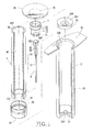
- Fig. 1 is an exploded perspective view of a first preferred embodiment of a safety syringe according to this invention;
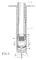
- Fig. 2 is a sectional view of the first preferred embodiment;
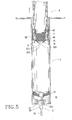
- Fig. 3 is a sectional view of a syringe barrel and a needle unit of the first preferred embodiment;
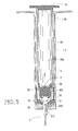
- Fig. 4 is a sectional view of a plunger and a sealing member of the first preferred embodiment;
- Fig. 5 illustrates how the sealing member is moved together with the plunger when the plunger is pulled rearward relative to the syringe barrel;
- Fig. 6 illustrates how a holder-retaining front portion of the sealing member of the first preferred embodiment engages a needle holder;
- Fig. 7 illustrates how a holder-supporting seat of the first preferred embodiment is pushed by the plunger to separate from the needle holder;
- Fig. 8 illustrates how the needle unit of the first preferred embodiment is retracted into the plunger;
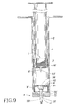
- Fig. 9 is a sectional view of a second preferred embodiment of a safety syringe according to this invention;
- Fig. 10 illustrates how a holder-retaining front portion of a sealing member of the second preferred embodiment engages a needle holder;
- Fig. 11 illustrates how a holder-supporting seat of the second preferred embodiment is pushed by a plunger to separate from the needle holder; and
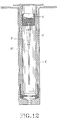
- Fig. 12 illustrates how a needle unit of the second preferred embodiment is retracted into the plunger.
-
- Referring to Figs. 1, 2, 3, and 4, a first preferred embodiment of a safety syringe according to this invention is shown to include a
syringe barrel 2, aneedle unit 3, aplunger 4, and aflexible sealing member 5. Theneedle unit 3 has aneedle holder 30, aneedle 31, aspacer portion 32 having a rear end that is formed integrally with a front end of theneedle holder 30, and a connectingportion 33 having a front end that is formed integrally with a rear end of theneedle 31, and a rear end that is formed integrally with a front end of thespacer portion 32. - The
syringe barrel 2 includes abarrel body 20, afront end wall 21 that is formed integrally with a front end of thebarrel body 20 and that has afront opening 210, arear end wall 22 that is formed integrally with a rear end of thebarrel body 20 and that has arear opening 220, and an annular flexible holder-supportingseat 24 with frustoconical front andrear end surfaces 241, each of which has a diameter that increases rearward. The holder-supportingseat 24 is sleeved on theneedle holder 30, and has acentral hole 240 formed therethrough, an outer periphery that is in frictional contact with an inner surface of thesyringe barrel 2 in such a manner that a liquid-tight seal is established therebetween, and an inner periphery that is in frictional contact with an outer surface of theneedle holder 30 of theneedle unit 3 in such a manner that a liquid-tight seal is established therebetween. - The
needle unit 3 is inserted into thesyringe barrel 2 through therear opening 220. The connectingportion 33 of theneedle unit 3 extends through the front opening 210 in thesyringe barrel 2. Theneedle 31 is exposed outwardly from thefront opening 210. Thespacer portion 32 is sized to prevent movement of thespacer portion 32 into the front opening 210. As such, theneedle holder 30 is clamped within thecentral hole 240 in the holder-supportingseat 24 at a position that is spaced apart from thefront end wall 21 at a predetermined distance. Theneedle holder 30 has a rear end that is formed with anoutward flange 303 which extends integrally, radially, and outwardly therefrom and which is sized to prevent forward movement of theoutward flange 303 into thecentral hole 240 in the holder-supportingseat 24. - The
plunger 4 is disposed movably within thesyringe barrel 2, and includes aplunger body 40 that has anopen front end 41 which is formed with afront opening 410 so that the sealingmember 5 can be placed into theplunger body 40 and can extend therethrough during assembly, and an openrear end 42 that is formed with arear opening 420. A unitaryrear end wall 45 has acircular projection 46 extending forwardly therefrom and press-fitted within therear opening 420 in theplunger body 40. When theplunger 4 is to be evacuated, therear end wall 45 can be removed from theplunger body 40 for evacuation of air from theplunger 4. Arubber seal ring 43 is disposed between theplunger 4 and thesyringe barrel 2 so as to establish a liquid-tight seal therebetween. Theplunger body 40 has a front end that is formed with aninward flange 44 extending integrally, radially, and inwardly therefrom. - The sealing
member 5 is disposed movably within the front end portion of theplunger 4 so as to define a vacuum chamber (40A) in theplunger 4 between the sealingmember 5 and therear wall 45. The sealingmember 5 is unitary, is made of rubber, and includes a holder-retainingfront portion 51 disposed behind and spaced apart from theneedle holder 30, a sealingrear portion 52 for closing thefront opening 410 in theplunger 4, a rearend skirt portion 53, and ashoulder 54 defined between the sealingrear portion 52 and theskirt portion 53. Theinward flange 44 of theplunger 4 is sleeved around and clamps the sealingrear portion 52 of the sealingmember 5 in theplunger 4 so as to prevent movement of the sealingmember 5 relative to theplunger 4, thereby permitting synchronous rearward movement of the sealingmember 5 and theplunger 4 when theplunger 4 is pulled rearward relative to thesyringe barrel 2. The holder-retainingfront portion 51 is shaped as an annular flange that extends forward and inwardly to define ablind hole 510 and that has a roundedfront end edge 511 for guiding movement of theoutward flange 303 of theneedle holder 30 into theblind hole 510 when theoutward flange 303 moves into theblind hole 510. Theblind hole 510 has a front end that has a diameter which is slightly smaller than that of theoutward flange 303 so as to confine theoutward flange 303 within theblind hole 510 when theoutward flange 303 moves into theblind hole 510, as shown in Figs. 6 and 7. The holder-retainingfront portion 51 is formed with acurved projection 520 that is located within theblind hole 510 and that is movable within thesyringe barrel 2 to seal therear opening 300 in theneedle holder 30 when theoutward flange 303 engages theblind hole 510. - Referring to Fig. 5, when the
plunger 4 is pulled rearward relative to thesyringe barrel 2 in order to draw a medical liquid, blood, or body liquid from a subject, a rear edge of theinward flange 44 of theplunger 4 engages theshoulder 54 of the sealingmember 5 so as to permit synchronous movement of the sealingmember 5 and theplunger 4. - When it is desired to inject a medical liquid into a body, the
plunger 4 is moved to a position shown in Fig. 6, where theoutward flange 303 of theneedle holder 30 engages theblind hole 510 in the sealingmember 5, and where a front end of theplunger body 40 comes into contact with the holder-supportingseat 24. Thereafter, the sealingmember 5 is blocked by theneedle holder 30 from further forward movement within thesyringe barrel 2. Theplunger 4 continues to move forward within thesyringe barrel 2 to a front limit position shown in Fig. 7, where the holder-supportingseat 24 is pushed by theplunger 4 to separate from theneedle holder 30 and where the rear sealingrear portion 52 of the sealingmember 5 is released from theinward flange 44 of theplunger 4. As such, an assembly of the sealingmember 5 and theneedle unit 3 will move rearward within theplunger 4 due to negative pressure produced within the evacuatedplunger 4 until it moves to a retracted position shown in Fig. 8, where theneedle unit 3 is concealed within theplunger 4. - Referring to Fig. 9, a second preferred embodiment of a safety syringe according to this invention is shown to include a syringe barrel 2', a needle unit 3', a plunger 4', and a
sealing member 5'. The differences between the first and second preferred embodiments are described in the succeeding paragraph. - The syringe barrel 2' includes a flexible holder-supporting seat 24' constructed as a hollow cylinder that has a surrounding wall 241' in frictional contact with an inner surface of the syringe barrel 2' , and a ring-shaped
rear end wall 242' sleeved around and clamping a rear end of a needle holder 30' of the needle unit 3' therein. Thecentral bore 310' in the needle unit 3' has an enlarged rear bore portion 304' that has a greatest diameter slightly greater than that of a rear opening 300' in the needle holder 30'. A holder-retaining front portion 51' of the sealingmember 5' includes a fixed flexible insert member 510' that is movable within the syringe barrel 2' to engage fittingly the enlarged rear bore portion 304' of thecentral bore 310' in the needle unit 3' so as to retain the needle holder 30' on the sealingmember 5'. The plunger 4' has a front end portion with an inward flange 44' that is configured as an annular rib which presses against a sealing rear portion 52' of the sealingmember 5'. As such, the sealingmember 5' can be removed forcibly from the plunger 4' for evacuation of air from the plunger 4'. The syringe barrel 2' has a front end wall 21' that is formed with a tapered front opening 210'. The needle unit 3' includes the needle holder 30', from which an outward flange similar to that in the previous embodiment is omitted, aneedle 31', a spacer portion 32', and a connecting portion 33'. An assembly of the spacer portion 32' and the connecting portion 33' is shaped as a truncated cone. The connecting portion 33' extends through the front opening 210' in the syringe barrel 2'. The spacer portion 32' is sized to prevent movement into the front opening 210'. - The plunger 4' is movable forward within the syringe barrel 2' to a position shown in Fig. 10, where the insert member 510' engages the enlarged bore portion 304' of the
central bore 310' in the needle unit 3' so as to prevent further forward movement of the sealingmember 5' within the syringe barrel 2' and where a front end of the plunger 4' comes into contact with the rear end wall 24'. - The
plunger 4 will continue to move forward within the syringe barrel 2' to a front limit position shown in Fig. 11, where the inward flange 44' separates from thesealing member 5' and where the surrounding wall 241' of the holder-supporting seat 24' deforms to permit forward removal of therear end wall 242' from the needle holder 30'. As such, the needle unit 3' can also be drawn into the plunger 4' due to negative pressure produced in the plunger 4', as shown in Fig. 12.
Claims (5)
- A safety syringe including:characterized by:a syringe barrel (2, 2') having a front end wall (21, 21') with a front opening (210, 210'), and a rear end wall (22) with a rear opening (220);a plunger (4, 4') disposed movably within the syringe barrel (2, 2') and having a front end (41) and a rear end (42) that extends from the rear opening (220) in the syringe barrel (2, 2'); anda needle unit (3, 3') extending through the front opening (210, 210') in the syringe barrel (2, 2') and including a central bore (310, 310') formed therethrough, a needle holder (30, 30') that is formed with a rear opening (300, 300'), and a needle (31) that is connected fixedly to the needle holder (30, 30') at a rear end and that is exposed outwardly from the front opening (210, 210') in the syringe barrel (2, 2');
the syringe barrel (2, 2') including an annular flexible holder-supporting seat (24, 24') disposed movably within the syringe barrel (2, 2') and sleeved around the needle holder (30, 30'), the holder-supporting seat (24, 24') having a central hole (240, 240') formed therethrough, an outer periphery that is in frictional contact with an inner surface of the syringe barrel (2, 2') in such a manner that a liquid-tight seal is established therebetween, and an inner periphery that is in frictional contact with an outer surface of the needle holder (30, 30') in such a manner that a liquid-tight seal is established therebetween;
said plunger (4, 4') having an open front end (41) that is formed with a front opening (410), a rear end wall (45) , and a front end portion that is formed with an inward flange (44, 44') extending integrally, radially, and inwardly therefrom;
a flexible sealing member (5, 5') being disposed movably within the front end portion of the plunger (4, 4') so as to define a vacuum chamber in the plunger (4, 4') between the sealing member (5, 5') and the rear end wall (45), the inward flange (44, 44') being sleeved around and clamping the sealing member (5, 5') in the plunger (4, 4') so as to prevent movement of the sealing member (5, 5') relative to the plunger (4, 4'), thereby permitting synchronous rearward movement of the sealing member (5, 5') and the plunger (4, 4') when the plunger (4, 4') is pulled rearward relative to the syringe barrel (2, 2'), the sealing member (5, 5') having a holder-retaining front portion (51, 51') that is disposed behind and that is spaced apart from the needle holder (30, 30'), and a sealing rear portion (52, 52') for closing the front opening (410) in the plunger (4, 4') ;
said needle unit (3, 3') having a spacer portion (32, 32') that is formed integrally between the needle holder (30, 30') and the needle (31, 31') and that is sized to prevent movement of the spacer portion (32, 32' ) into the front opening (210, 210')) in the syringe barrel (2, 2') such that the needle holder (30, 30') is clamped within the holder-supporting seat (24, 24') at a position that is spaced apart from the front end wall (21, 21') by a predetermined distance;
said holder-retaining front portion (51, 51') of the sealing member (5, 5' ) moving forward to retain the needle holder (30, 30') thereon when the plunger (4, 4') is moved forward within the syringe barrel (2, 2') to push the holder-supporting seat (24, 24') forward such that the holder-supporting seat (24, 24') separates from the needle holder (30, 30') so as to permit automatic rearward movement of an assembly of the sealing member (5, 5' ) and the needle unit (3, 3') within the syringe barrel (2, 2') due to negative pressure produced within the plunger (4, 4'), thereby retracting the needle (31, 31') into the syringe barrel (2, 2'). - The safety syringe as claimed in Claim 1, characterized in that the needle unit (3) is formed with an outward flange (303) that extends integrally, radially, and outwardly from a rear end of the needle holder (30) and that is sized to prevent forward movement of the outward flange (303) into the central hole (240) in the holder-supporting seat (24), the holder-retaining front portion (51) of the sealing member (5) being shaped as an annular flange that extends forwardly and inwardly to define a blind hole (510) and that has a rounded front end (511) for guiding movement of the outward flange (303) of the needle holder (30) into the blind hole (510) , the blind hole (510) including a front end that has a diameter which is slightly smaller than that of the outward flange (303) of the needle unit (3) so as to confine the outward flange (303) within the blind hole (510) when the outward flange (303) moves into the blind hole (510).
- The safety syringe as claimed in Claim 2, further characterized in that the holder-retaining front portion (51) of the sealing member (5) is formed with a curved projection (520) that is located within the blind hole (510) and that is movable within the syringe barrel (2) to seal the rear opening (300) in the needle holder (30) when the outward flange (303) engages the blind hole (510).
- The safety syringe as claimed in Claim 1, characterized in that the plunger (4) includes a plunger body (40) that has an open rear end (420) so that the sealing member (5) can be placed into the plunger body (40) and can extend therethrough during assembly, the rear end wall (45) of the plunger (4) being unitary and having a circular proj ection (46) that extends forwardly therefrom and that is press-fitted within the rear end (420) of the plunger body (40) so as to be removable from the plunger body (40) .
- The safety syringe as claimed in Claim 1, characterized in that the holder-supporting seat (24' ) is constructed as a hollow cylinder that has a surrounding wall (241') in frictional contact with the inner surface of the syringe barrel (2'), and a ring-shaped rear end wall (242') sleeved around and clamping a rear end of the needle holder (30') therein, the central bore (310') in the needle unit (3') having an enlarged rear bore portion (304') that has a greatest diameter slightly greater than that of the rear opening (300') in the needle holder (30'), the holder-retaining front portion (51') of the sealing member (5') including a fixed flexible insert member (510') that is movable within the syringe barrel (2') to engage fittingly the enlarged rear bore portion (304') of the central bore (310') so as to retain the needle holder (30') on the sealing member (5').
Priority Applications (1)
| Application Number | Priority Date | Filing Date | Title |
|---|---|---|---|
| EP03250511A EP1442763A1 (en) | 2003-01-28 | 2003-01-28 | Safety syringe with needle retracted by vacuum |
Applications Claiming Priority (1)
| Application Number | Priority Date | Filing Date | Title |
|---|---|---|---|
| EP03250511A EP1442763A1 (en) | 2003-01-28 | 2003-01-28 | Safety syringe with needle retracted by vacuum |
Publications (1)
| Publication Number | Publication Date |
|---|---|
| EP1442763A1 true EP1442763A1 (en) | 2004-08-04 |
Family
ID=32605395
Family Applications (1)
| Application Number | Title | Priority Date | Filing Date |
|---|---|---|---|
| EP03250511A Withdrawn EP1442763A1 (en) | 2003-01-28 | 2003-01-28 | Safety syringe with needle retracted by vacuum |
Country Status (1)
| Country | Link |
|---|---|
| EP (1) | EP1442763A1 (en) |
Cited By (5)
| Publication number | Priority date | Publication date | Assignee | Title |
|---|---|---|---|---|
| FR2898504A1 (en) * | 2006-02-14 | 2007-09-21 | Feng Hui Lu | Safety injection syringe used in medicine for injecting liquid medicine comprises a cylinder, a connecting rod inserted into the hollow passage of the cylinder, a drive group and a needle holder inserted into the pump of the drive group |
| EP1900386A1 (en) * | 2006-08-22 | 2008-03-19 | Wang, Chih Ming | Safety seringue |
| CN100502965C (en) * | 2006-01-25 | 2009-06-24 | 吕丰辉 | safety syringe |
| WO2010006380A1 (en) * | 2008-07-17 | 2010-01-21 | Medigard Limited | A retractable syringe |
| WO2016116726A1 (en) * | 2015-01-20 | 2016-07-28 | Commodious Llp | Syringe with needle retractable into the plunger by vacuum |
Citations (6)
| Publication number | Priority date | Publication date | Assignee | Title |
|---|---|---|---|---|
| US5000736A (en) * | 1990-03-22 | 1991-03-19 | Harry Kaufhold, Jr. | Disposable syringe with automatic needle retraction |
| US5084018A (en) * | 1989-08-14 | 1992-01-28 | Tsao Chien Hua | Safety syringe |
| FR2675999A1 (en) * | 1991-04-30 | 1992-11-06 | Ferras Jean | Safety syringe |
| US6077245A (en) * | 1999-02-18 | 2000-06-20 | Texas Applied Biomedical Services, Inc. | Disposable syringe with retractable needle |
| US6413236B1 (en) * | 1999-10-08 | 2002-07-02 | Lewis R. Van Dyke | Automatically retractable needle safety syringe |
| US6494863B1 (en) * | 2001-10-15 | 2002-12-17 | Retractable Technologies, Inc. | One-use retracting syringe with positive needle retention |
-
2003
- 2003-01-28 EP EP03250511A patent/EP1442763A1/en not_active Withdrawn
Patent Citations (6)
| Publication number | Priority date | Publication date | Assignee | Title |
|---|---|---|---|---|
| US5084018A (en) * | 1989-08-14 | 1992-01-28 | Tsao Chien Hua | Safety syringe |
| US5000736A (en) * | 1990-03-22 | 1991-03-19 | Harry Kaufhold, Jr. | Disposable syringe with automatic needle retraction |
| FR2675999A1 (en) * | 1991-04-30 | 1992-11-06 | Ferras Jean | Safety syringe |
| US6077245A (en) * | 1999-02-18 | 2000-06-20 | Texas Applied Biomedical Services, Inc. | Disposable syringe with retractable needle |
| US6413236B1 (en) * | 1999-10-08 | 2002-07-02 | Lewis R. Van Dyke | Automatically retractable needle safety syringe |
| US6494863B1 (en) * | 2001-10-15 | 2002-12-17 | Retractable Technologies, Inc. | One-use retracting syringe with positive needle retention |
Cited By (9)
| Publication number | Priority date | Publication date | Assignee | Title |
|---|---|---|---|---|
| CN100502965C (en) * | 2006-01-25 | 2009-06-24 | 吕丰辉 | safety syringe |
| FR2898504A1 (en) * | 2006-02-14 | 2007-09-21 | Feng Hui Lu | Safety injection syringe used in medicine for injecting liquid medicine comprises a cylinder, a connecting rod inserted into the hollow passage of the cylinder, a drive group and a needle holder inserted into the pump of the drive group |
| EP1900386A1 (en) * | 2006-08-22 | 2008-03-19 | Wang, Chih Ming | Safety seringue |
| WO2010006380A1 (en) * | 2008-07-17 | 2010-01-21 | Medigard Limited | A retractable syringe |
| CN102131539B (en) * | 2008-07-17 | 2013-04-24 | 医疗卫士有限公司 | Retractable syringe |
| AU2009270343B2 (en) * | 2008-07-17 | 2013-10-03 | Medigard Limited | A retractable syringe |
| US8632493B2 (en) | 2008-07-17 | 2014-01-21 | Medigard Limited | Retractable syringe |
| EP2313135A4 (en) * | 2008-07-17 | 2017-10-11 | Medigard Limited | A retractable syringe |
| WO2016116726A1 (en) * | 2015-01-20 | 2016-07-28 | Commodious Llp | Syringe with needle retractable into the plunger by vacuum |
Similar Documents
| Publication | Publication Date | Title |
|---|---|---|
| US5215533A (en) | Safety syringe incorporating vacuum retraction of the needle | |
| AU2009270343B2 (en) | A retractable syringe | |
| US6743199B2 (en) | Disposable syringe | |
| US7147621B2 (en) | Single use syringe | |
| AU4195799A (en) | Self-retracting iv catheter introducer | |
| MXPA05003675A (en) | Iv catheter introducer with retractable needle. | |
| US6193687B1 (en) | Safety hypodermic syringe | |
| US6733475B2 (en) | Safety syringe of easy to pull out the plunger | |
| CA2409297C (en) | Retractable needle and syringe combination | |
| CA2642894A1 (en) | A needle containing medical device with variable locking to needle holder | |
| CA2486511C (en) | Single-use syringe | |
| US7074207B2 (en) | Safety syringe | |
| JP4253295B2 (en) | Safety syringe | |
| EP1442763A1 (en) | Safety syringe with needle retracted by vacuum | |
| EP1237600B1 (en) | Improvements in or relating to hypodermic syringes | |
| EP2060291B1 (en) | Safety disposable syringe | |
| EP1421962B1 (en) | Disposable syringe | |
| US20040153034A1 (en) | Safety fluid injecting/sampling apparatus | |
| KR200219758Y1 (en) | Safety hypodermic syringe | |
| CA2454299A1 (en) | Safety fluid injecting/sampling apparatus | |
| CN221310387U (en) | Medicine dissolving device with rubber plug limiting structure | |
| EP1629858A1 (en) | Single-use syringe | |
| WO2001072363A1 (en) | Retractable syringe | |
| CN101400395A (en) | Needle-containing medical device with differential locking of needle holder |
Legal Events
| Date | Code | Title | Description |
|---|---|---|---|
| PUAI | Public reference made under article 153(3) epc to a published international application that has entered the european phase |
Free format text: ORIGINAL CODE: 0009012 |
|
| AK | Designated contracting states |
Kind code of ref document: A1 Designated state(s): AT BE BG CH CY CZ DE DK EE ES FI FR GB GR HU IE IT LI LU MC NL PT SE SI SK TR |
|
| AX | Request for extension of the european patent |
Extension state: AL LT LV MK RO |
|
| 17P | Request for examination filed |
Effective date: 20041105 |
|
| AKX | Designation fees paid |
Designated state(s): AT BE BG CH CY CZ DE DK EE ES FI FR GB GR HU IE IT LI LU MC NL PT SE SI SK TR |
|
| 17Q | First examination report despatched |
Effective date: 20060719 |
|
| 17Q | First examination report despatched |
Effective date: 20060719 |
|
| RAP1 | Party data changed (applicant data changed or rights of an application transferred) |
Owner name: CHUANG, CHUN-CHIEH Owner name: LEE, PO-LIANG Owner name: TSENG, HSI-HSUN Owner name: WANG, CHIH MING |
|
| STAA | Information on the status of an ep patent application or granted ep patent |
Free format text: STATUS: THE APPLICATION IS DEEMED TO BE WITHDRAWN |
|
| 18D | Application deemed to be withdrawn |
Effective date: 20140805 |