EP1237600B1 - Improvements in or relating to hypodermic syringes - Google Patents
Improvements in or relating to hypodermic syringes Download PDFInfo
- Publication number
- EP1237600B1 EP1237600B1 EP00988968A EP00988968A EP1237600B1 EP 1237600 B1 EP1237600 B1 EP 1237600B1 EP 00988968 A EP00988968 A EP 00988968A EP 00988968 A EP00988968 A EP 00988968A EP 1237600 B1 EP1237600 B1 EP 1237600B1
- Authority
- EP
- European Patent Office
- Prior art keywords
- needle
- housing
- plunger
- carrier
- needle carrier
- Prior art date
- Legal status (The legal status is an assumption and is not a legal conclusion. Google has not performed a legal analysis and makes no representation as to the accuracy of the status listed.)
- Expired - Lifetime
Links
- 230000008878 coupling Effects 0.000 claims abstract description 4
- 238000010168 coupling process Methods 0.000 claims abstract description 4
- 238000005859 coupling reaction Methods 0.000 claims abstract description 4
- 208000012266 Needlestick injury Diseases 0.000 abstract description 5
- 210000002445 nipple Anatomy 0.000 description 5
- 239000012530 fluid Substances 0.000 description 4
- 230000006378 damage Effects 0.000 description 3
- 238000002347 injection Methods 0.000 description 3
- 239000007924 injection Substances 0.000 description 3
- 230000004048 modification Effects 0.000 description 3
- 238000012986 modification Methods 0.000 description 3
- 208000027418 Wounds and injury Diseases 0.000 description 2
- 230000009471 action Effects 0.000 description 2
- 208000006454 hepatitis Diseases 0.000 description 2
- 231100000283 hepatitis Toxicity 0.000 description 2
- 208000015181 infectious disease Diseases 0.000 description 2
- 208000014674 injury Diseases 0.000 description 2
- 238000000034 method Methods 0.000 description 2
- 230000008569 process Effects 0.000 description 2
- 206010069803 Injury associated with device Diseases 0.000 description 1
- 230000008901 benefit Effects 0.000 description 1
- 230000036541 health Effects 0.000 description 1
- 238000003780 insertion Methods 0.000 description 1
- 230000037431 insertion Effects 0.000 description 1
- 239000000314 lubricant Substances 0.000 description 1
- 239000000463 material Substances 0.000 description 1
- 230000007246 mechanism Effects 0.000 description 1
- 230000002093 peripheral effect Effects 0.000 description 1
- 239000004033 plastic Substances 0.000 description 1
- 229920003023 plastic Polymers 0.000 description 1
- 230000001681 protective effect Effects 0.000 description 1
- 230000000717 retained effect Effects 0.000 description 1
- 238000007789 sealing Methods 0.000 description 1
- 239000000243 solution Substances 0.000 description 1
- 230000001960 triggered effect Effects 0.000 description 1
Images
Classifications
-
- A—HUMAN NECESSITIES
- A61—MEDICAL OR VETERINARY SCIENCE; HYGIENE
- A61M—DEVICES FOR INTRODUCING MEDIA INTO, OR ONTO, THE BODY; DEVICES FOR TRANSDUCING BODY MEDIA OR FOR TAKING MEDIA FROM THE BODY; DEVICES FOR PRODUCING OR ENDING SLEEP OR STUPOR
- A61M5/00—Devices for bringing media into the body in a subcutaneous, intra-vascular or intramuscular way; Accessories therefor, e.g. filling or cleaning devices, arm-rests
- A61M5/178—Syringes
- A61M5/31—Details
- A61M5/32—Needles; Details of needles pertaining to their connection with syringe or hub; Accessories for bringing the needle into, or holding the needle on, the body; Devices for protection of needles
- A61M5/3205—Apparatus for removing or disposing of used needles or syringes, e.g. containers; Means for protection against accidental injuries from used needles
- A61M5/321—Means for protection against accidental injuries by used needles
- A61M5/322—Retractable needles, i.e. disconnected from and withdrawn into the syringe barrel by the piston
- A61M5/3234—Fully automatic needle retraction, i.e. in which triggering of the needle does not require a deliberate action by the user
- A61M2005/3241—Needle retraction energy is accumulated inside of a hollow plunger rod
- A61M2005/3242—Needle retraction by vacuum
-
- A—HUMAN NECESSITIES
- A61—MEDICAL OR VETERINARY SCIENCE; HYGIENE
- A61M—DEVICES FOR INTRODUCING MEDIA INTO, OR ONTO, THE BODY; DEVICES FOR TRANSDUCING BODY MEDIA OR FOR TAKING MEDIA FROM THE BODY; DEVICES FOR PRODUCING OR ENDING SLEEP OR STUPOR
- A61M5/00—Devices for bringing media into the body in a subcutaneous, intra-vascular or intramuscular way; Accessories therefor, e.g. filling or cleaning devices, arm-rests
- A61M5/178—Syringes
- A61M5/31—Details
- A61M5/32—Needles; Details of needles pertaining to their connection with syringe or hub; Accessories for bringing the needle into, or holding the needle on, the body; Devices for protection of needles
- A61M5/3202—Devices for protection of the needle before use, e.g. caps
-
- A—HUMAN NECESSITIES
- A61—MEDICAL OR VETERINARY SCIENCE; HYGIENE
- A61M—DEVICES FOR INTRODUCING MEDIA INTO, OR ONTO, THE BODY; DEVICES FOR TRANSDUCING BODY MEDIA OR FOR TAKING MEDIA FROM THE BODY; DEVICES FOR PRODUCING OR ENDING SLEEP OR STUPOR
- A61M5/00—Devices for bringing media into the body in a subcutaneous, intra-vascular or intramuscular way; Accessories therefor, e.g. filling or cleaning devices, arm-rests
- A61M5/178—Syringes
- A61M5/31—Details
- A61M5/32—Needles; Details of needles pertaining to their connection with syringe or hub; Accessories for bringing the needle into, or holding the needle on, the body; Devices for protection of needles
- A61M5/34—Constructions for connecting the needle, e.g. to syringe nozzle or needle hub
- A61M5/344—Constructions for connecting the needle, e.g. to syringe nozzle or needle hub using additional parts, e.g. clamping rings or collets
Definitions
- This invention relates to hypodermic syringes and particularly to a syringe in which the needle can be withdrawn.
- US-A-5211628 discloses a hypodermic syringe with a housing, a plunger, a needle carrier with a needle mounted thereto, the needle carrier being mounted on the housing in a housing aperture, with the needle extending outwardly from the housing, and a stored energy configuration, the plunger and the stored energy configuration being arranged so that when the syringe is used and the plunger moves towards the needle carrier, it become attached thereto and the stored energy in the stored energy configuration is released to retract the needle carrier and the needle into the housing through the housing aperture.
- a hypodermic syringe according to the preamble of claim 1 is known from document US-A-5 578 015.
- the needle may be attached to the housing by a push fit. If the needle is push fitted to the movable needle carrier, to provide needle interchangeability, there is problem that the stored energy configuration, when withdrawing the needle carrier into the housing, may cause the needle to become detached from the needle carrier. It has been proposed in conventional syringes to securely attach a needle to the syringe using a so-called "Luer lock" which requires rotation of the needle axially relative to its mounting, so as to lock it in position. However, such a locking arrangement cannot be readily used with a retractable needle carrier because rotation of the needle will also produce rotation of the needle carrier relative to the housing making it difficult to secure engagement between them.
- the housing aperture and the needle carrier are configured so as not to rotate relative to one another about the longitudinal access of the needle.
- a sheath may be mounted on the needle carrier surrounding the needle, so as to be removable from the carrier utilising an axial rotation of the sheath.
- the needle may be interchangeably mounted and lockable onto the needle carrier by axial rotation of the needle relative to the carrier, for example utilising a Luer lock. Since the needle carrier is constrained from rotation relative to the housing, interchange of the needle on the needle carrier can be readily achieved according to the invention.
- the housing aperture and the needle carrier may be configured so that the needle and sheath can be fitted within the housing.
- the aperture and the co-acting portion of the needle carrier are non-circular and configured to permit withdrawal of the needle carrier into the housing on release of the stored energy configuration and to prevent relative axial rotation thereof.
- the co-acting portion of the needle carrier and the aperture may be rectangular in transverse cross-section.
- a piston may be slidably mounted in the housing and releasably coupled to the plunger, the piston being operable when the plunger is moved towards the needle carrier to engage it such that the coupling between the piston and the plunger is released with the result that the stored energy configuration is released so as to retract the needle carried into the housing.
- the stored energy configuration may comprise a vacuum which may be established between the piston and the plunger either internally during assembly of the syringe or by external means after or during assembly of the syringe.
- Alternative sources of stored energy may be used such as a spring.
- the housing aperture is sufficiently large to permit a bent needle to be withdrawn into the housing.
- the syringe comprises a generally cylindrical housing 1 that has an open end 1.1 that receives a plunger 2 with an associated piston 3.
- the housing 1 contains a housing aperture 1.2 which receives the needle carrier 4 on which a needle 5 is mounted such that the longitudinal axis thereof is coaxial with the longitudinal axis of the housing 1 and slidable plunger 2.
- a sheath 6 with a removable end cap 7 is mounted on a coaxial flange 4.1 on the needle carrier 4.
- the plunger and piston arrangement is operated in a conventional manner to force an injectant through the needle 5 into a patient.
- the syringe is provided with an automatic needle withdrawal mechanism as will now be explained.
- the plunger 2 and piston 3 are assembled so as to create a vacuum in the interior space between them, which provides a stored energy configuration for withdrawing the needle, as will be explained later.
- the piston 3 is provided with a triangular sectioned ring 3.1 and the plunger is provided with a sealing surface 2.1 and a plunger head 2.2 which has a radially inwardly facing lip 2.3 that lodges against the triangular sectioned ring 3.1 to provide a releasable coupling.
- the piston 3 carries a seal 8 which slidably, sealingly engages the inner surface 2.4 of the plunger 2.
- a closure piece 9 on the plunger 2 is fixedly held in place by a wedge section ring 2.5 on the plunger.
- the needle carrier is formed with a cup 4.2, provided with an abutment lip 4.3, which is fixed onto the main body 4 of the needle carrier, as can be seen clearly in Figure 3.
- the cup 4.2 is provided with an annular lip 4.4 for receiving a head 3.2 on the piston.
- the piston head 3.2 is grooved to provide a by-pass 3.4 and includes a fluid passage 3.5.
- the piston 3 and the closure piece 9 are placed with their surfaces 10, 11 in contact with one another, so as to be held together using an appropriate lubricant. They are then inserted as one piece through the end of the plunger 2 and the closure piece 9 is inserted into groove 2.5. Thereafter, the piston 3 is slid axially along the plunger until the triangular section ring 3.1 snaps past the inward facing lip 2.3, thereby creating and maintaining a vacuum inside the plunger 2 and holding the piston 3 and plunger 2 together as once piece. The plunger closure 9 remains at the end of the plunger 2. The plunger and piston assembly is then ready for insertion into the housing 1.
- the assembly of the needle carrier 4, which includes the needle 5 together with sheath 6 and end cap 7, is inserted into the housing, so as to protrude through the housing aperture 1.2, with the abutment 4.3 engaging the interior of the aperture.
- the aperture 1.2 is sufficiently large to allow the passage of the needle 5, pre-shrouded by the protective sheath 6.
- the needle sheath and end cap 6, 7 thus affords protection to the needle 5 and also guidance when entering and locating the needle assembly in the housing apertures 1.2.
- the pull exerted by the vacuum on the cup 4.2 during retraction elongates the cup 4.3 axially, thereby reducing its radial pressure against the interior wall of the housing 1 allowing free movement axially inwardly of the housing 1.
- the housing aperture 1.2 and the needle carrier 4 are square in cross-section such that when the needle carrier is received in the housing aperture 1.2 it is prevented from rotating about the axis of the needle 5.
- this has the advantage that when the user wishes to remove the sheath 6, this can be done by axially twisting the sheath so to remove it from the mounting region 4.1. Without this feature, the needle carrier would rotate, making it extremely difficult to remove the needle sheath without the risk of a needle stick injury.
- FIG. 2 Another embodiment of the invention is shown in Figure 2 wherein like parts are marked with the same reference numerals used in Figure 1.
- the vacuum produced between the plunger 2 and piston 3 is created by using a vacuum pump or other source of vacuum that is coupled to orifice 9.1 so as to extract air from the interior space between the plunger 2 and piston 3.
- the orifice is thereafter sealed to maintain the vacuum.
- the plunger is operated as previously described with reference to Figure 1 so that when the piston head 3.2 engages the cup shaped member 4.2 on the needle carrier, further depression of the plunger breaks the releasable connection between the plunger 2 and piston 3, with the result that the vacuum withdraws the needle carrier 4 together with the needle 5 axially into the housing 1.
- the structure of the housing aperture 1.2 and the needle carrier 4 is non-circular, as shown in Figure 3, so as to prevent axial rotation of the needle carrier relative to the housing 1.
- the needle carrier 4 and housing aperture 1.2 could be of other mutually co-operating non-circular shapes which prevent axial rotation of the needle carrier relative to the housing. It will be understood that the configuration eases the breaking of friction between the needle sheath 6 and the needle carrier 4 when the needle sheath is partially rotated, thus facilitating easier withdrawal of the needle sheath and consequently reducing the risk of damage and/or injury during this process.
- the described examples of the invention have the capacity to retract a bent needle without it jamming against the side walls of the housing.
- Needle 5 is provided with a mounting nipple 5.1 with diametrically opposed end cams 5.2, 5.3.
- the nipple 5.1 which may be made of plastics material, is provided with an interior axial bore 5.4.
- the needle carrier 4 includes a central cylindrical spigot 4.5, which includes an axial bore 4.6 through which injectant is supplied to the needle 5.
- the spigot 4.5 is formed axially within a mounting recess 4.7 to receive the bore 5.4 of the nipple 5.1, the mounting recess including detents 4.8, 4.9 to receive the cams 5.2. 5.3.
- the needle can be mounted onto the needle carrier by aligning the cams 5.2, 5.3 with the corresponding detents 4.8, 4.9 and axially inserting the nipple 5.1 into the mounting recess 4.7. Then, by axially rotating the needle so as to axially rotate the cams 5.2, 5.3 and misalign them with the detents 4.8, 4.9, the needle 5 becomes locked into the needle carrier 4. The locking can be released by axially counter-rotating the needle 5 relative to the needle carrier 4 and subsequently withdrawing it in a reverse manner.
- the needle sheath 6 is provided with a peripheral mounting ring 6.1 which may be frictionally engaged or otherwise releasably gripped onto the needle nipple 5.1.
- a peripheral mounting ring 6.1 which may be frictionally engaged or otherwise releasably gripped onto the needle nipple 5.1.
- rotation of the needle 5 to lock it in place can be achieved by gripping the needle sheath 6 and rotating the entire assembly.
- the needle can be removed in a reverse manner by gripping the sheath. Since the needle carrier 4 is rectangular in cross section and prevented from rotation by the corresponding shape of housing aperture 1.2, mounting and release of the needle from the needle carrier is readily facilitated in accordance with the invention.
- the needle 5 is positively locked into the needle carrier 4, thereby minimising the risk of the needle becoming detached as a result of the withdrawal process.
- a so-called Lure lock can be provided between the needle and the needle carrier, such that the needle can be rotated to achieve the desired locking action, without corresponding rotation of the needle carrier 4.
Landscapes
- Health & Medical Sciences (AREA)
- Engineering & Computer Science (AREA)
- Heart & Thoracic Surgery (AREA)
- Vascular Medicine (AREA)
- Anesthesiology (AREA)
- Biomedical Technology (AREA)
- Environmental & Geological Engineering (AREA)
- Hematology (AREA)
- Life Sciences & Earth Sciences (AREA)
- Animal Behavior & Ethology (AREA)
- General Health & Medical Sciences (AREA)
- Public Health (AREA)
- Veterinary Medicine (AREA)
- Infusion, Injection, And Reservoir Apparatuses (AREA)
Abstract
Description
- This invention relates to hypodermic syringes and particularly to a syringe in which the needle can be withdrawn.
- Over recent years, the use of disposable syringes and needles has become increasingly dangerous. Although the risk of accidental scratch or puncture by a used needle, a so-called needle stick injury, has always existed, the increased risk of infection with, for example HIV or hepatitis has become a growing concern to all involved in the provision of health care.
- It is estimated that in the USA, there are approximately 1,000,000 needle stick injuries annually which result in some 20,000 instances of infection with HIV or hepatitis. The consequent cost of these injuries is estimated at US$3 billion per annum. Hypodermic syringes with a retracting needle have been proposed, so that the needle is retracted after use to avoid needle stick injuries. For example US-A-5211628 discloses a hypodermic syringe with a housing, a plunger, a needle carrier with a needle mounted thereto, the needle carrier being mounted on the housing in a housing aperture, with the needle extending outwardly from the housing, and a stored energy configuration, the plunger and the stored energy configuration being arranged so that when the syringe is used and the plunger moves towards the needle carrier, it become attached thereto and the stored energy in the stored energy configuration is released to retract the needle carrier and the needle into the housing through the housing aperture.
- In our WO 00/18454 there is described a disposable syringe in which the needle is fitted with a sheath that is attached to the needle carrier. The pre-sheathed needle is fitted into the housing aperture from within the housing thereby reducing the risk of needle injuries. A problem with this arrangement is that when the user wishes to remove the sheath, the needle carrier, which is circular in cross-section rotates within the housing aperture, making it difficult to remove the sheath by the usual twisting action.
- A hypodermic syringe according to the preamble of
claim 1 is known from document US-A-5 578 015. - Another problem arises if it is desired to make the needle detachable from the needle carrier. In a conventional syringe, the needle may be attached to the housing by a push fit. If the needle is push fitted to the movable needle carrier, to provide needle interchangeability, there is problem that the stored energy configuration, when withdrawing the needle carrier into the housing, may cause the needle to become detached from the needle carrier. It has been proposed in conventional syringes to securely attach a needle to the syringe using a so-called "Luer lock" which requires rotation of the needle axially relative to its mounting, so as to lock it in position. However, such a locking arrangement cannot be readily used with a retractable needle carrier because rotation of the needle will also produce rotation of the needle carrier relative to the housing making it difficult to secure engagement between them.
- The present invention provides a solution to this problem. In accordance with the present invention, the housing aperture and the needle carrier are configured so as not to rotate relative to one another about the longitudinal access of the needle.
- Thus, a sheath may be mounted on the needle carrier surrounding the needle, so as to be removable from the carrier utilising an axial rotation of the sheath.
- The needle may be interchangeably mounted and lockable onto the needle carrier by axial rotation of the needle relative to the carrier, for example utilising a Luer lock. Since the needle carrier is constrained from rotation relative to the housing, interchange of the needle on the needle carrier can be readily achieved according to the invention.
- The housing aperture and the needle carrier may be configured so that the needle and sheath can be fitted within the housing.
- The aperture and the co-acting portion of the needle carrier are non-circular and configured to permit withdrawal of the needle carrier into the housing on release of the stored energy configuration and to prevent relative axial rotation thereof. The co-acting portion of the needle carrier and the aperture may be rectangular in transverse cross-section.
- A piston may be slidably mounted in the housing and releasably coupled to the plunger, the piston being operable when the plunger is moved towards the needle carrier to engage it such that the coupling between the piston and the plunger is released with the result that the stored energy configuration is released so as to retract the needle carried into the housing.
- The stored energy configuration may comprise a vacuum which may be established between the piston and the plunger either internally during assembly of the syringe or by external means after or during assembly of the syringe. Alternative sources of stored energy may be used such as a spring.
- Preferably, the housing aperture is sufficiently large to permit a bent needle to be withdrawn into the housing.
- In order that the invention may be more fully understood embodiments thereof will now be described by way of example with reference to the accompanying drawings in which:
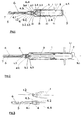
- Figure 1 is a schematic cross-section of a first embodiment of the invention;
- Figure 2 is a schematic cross-section of a second embodiment of a syringe according to the invention;
- Figure 3 is a schematic exploded illustration of the needle carrier and housing aperture in the syringes shown in Figures 1 and 2;
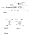
- Figure 4A is an exploded view of a needle carrier and changeable needle and sheath arrangement according to a modification; and
- Figures 4B and 4C are end views of the needle and needle carrier respectively.
- Referring to Figure 1, the syringe comprises a generally
cylindrical housing 1 that has an open end 1.1 that receives aplunger 2 with an associatedpiston 3. Thehousing 1 contains a housing aperture 1.2 which receives theneedle carrier 4 on which aneedle 5 is mounted such that the longitudinal axis thereof is coaxial with the longitudinal axis of thehousing 1 andslidable plunger 2. Asheath 6 with aremovable end cap 7 is mounted on a coaxial flange 4.1 on theneedle carrier 4. - In use, the plunger and piston arrangement is operated in a conventional manner to force an injectant through the
needle 5 into a patient. Additionally, the syringe is provided with an automatic needle withdrawal mechanism as will now be explained. - The
plunger 2 andpiston 3 are assembled so as to create a vacuum in the interior space between them, which provides a stored energy configuration for withdrawing the needle, as will be explained later. To this end, thepiston 3 is provided with a triangular sectioned ring 3.1 and the plunger is provided with a sealing surface 2.1 and a plunger head 2.2 which has a radially inwardly facing lip 2.3 that lodges against the triangular sectioned ring 3.1 to provide a releasable coupling. Thepiston 3 carries a seal 8 which slidably, sealingly engages the inner surface 2.4 of theplunger 2. A closure piece 9 on theplunger 2, is fixedly held in place by a wedge section ring 2.5 on the plunger. - The needle carrier is formed with a cup 4.2, provided with an abutment lip 4.3, which is fixed onto the
main body 4 of the needle carrier, as can be seen clearly in Figure 3. The cup 4.2 is provided with an annular lip 4.4 for receiving a head 3.2 on the piston. The piston head 3.2 is grooved to provide a by-pass 3.4 and includes a fluid passage 3.5. - In order to produce a vacuum between the plunger and the
piston 3 during assembly, thepiston 3 and the closure piece 9 are placed with theirsurfaces 10, 11 in contact with one another, so as to be held together using an appropriate lubricant. They are then inserted as one piece through the end of theplunger 2 and the closure piece 9 is inserted into groove 2.5. Thereafter, thepiston 3 is slid axially along the plunger until the triangular section ring 3.1 snaps past the inward facing lip 2.3, thereby creating and maintaining a vacuum inside theplunger 2 and holding thepiston 3 and plunger 2 together as once piece. The plunger closure 9 remains at the end of theplunger 2. The plunger and piston assembly is then ready for insertion into thehousing 1. - However, before inserting the piston and plunger assembly, the assembly of the
needle carrier 4, which includes theneedle 5 together withsheath 6 andend cap 7, is inserted into the housing, so as to protrude through the housing aperture 1.2, with the abutment 4.3 engaging the interior of the aperture. The aperture 1.2 is sufficiently large to allow the passage of theneedle 5, pre-shrouded by theprotective sheath 6. The needle sheath andend cap needle 5 and also guidance when entering and locating the needle assembly in the housing apertures 1.2. - Operation of the syringe follows the established practice for disposable syringes.
On completion of an injection stroke, automatic needle retraction is triggered by continued pressure on theplunger 2 by the user. Referring to Figure 1, pressure on the plunger moves the plunger and the piston together as a single piece through the interior of thehousing 1 towards theneedle carrier 4, thereby expelling the injectant through theneedle 5. When thepiston 3 meets the end wall of thehousing 1, the piston head 3.2 enters the cup 4.2 of theneedle carrier 4 and is retained by the lip 4.4. The injectant fluid can then flow along the by-pass 3.4 and the fluid passage 3.5 thereby avoiding a fluid lock. Further inward movement of thepiston 3 is now prohibited by thehousing 1 and as a result, further inward pressure of theplunger 2 snaps the inward facing lip 2.3 past the triangular section ring 3.1, thereby releasing thepiston 3 to slide relative to theplunger 2. As a result, the vacuum within theplunger 2 draws thepiston 3 and theneedle carrier 4 attached to it, into theplunger 2 thereby withdrawing theneedle carrier 4 and theneedle 5 automatically. - The pull exerted by the vacuum on the cup 4.2 during retraction elongates the cup 4.3 axially, thereby reducing its radial pressure against the interior wall of the
housing 1 allowing free movement axially inwardly of thehousing 1. - Referring now to Figure 3, it can be seen that the housing aperture 1.2 and the
needle carrier 4 are square in cross-section such that when the needle carrier is received in the housing aperture 1.2 it is prevented from rotating about the axis of theneedle 5. Thus, during assembly, when the needle carrier is inserted into the housing aperture 1.2 from within thehousing 1, it is locked against rotation. In accordance with the invention, this has the advantage that when the user wishes to remove thesheath 6, this can be done by axially twisting the sheath so to remove it from the mounting region 4.1. Without this feature, the needle carrier would rotate, making it extremely difficult to remove the needle sheath without the risk of a needle stick injury. - Another embodiment of the invention is shown in Figure 2 wherein like parts are marked with the same reference numerals used in Figure 1. In this embodiment, the vacuum produced between the
plunger 2 andpiston 3 is created by using a vacuum pump or other source of vacuum that is coupled to orifice 9.1 so as to extract air from the interior space between theplunger 2 andpiston 3. The orifice is thereafter sealed to maintain the vacuum. The plunger is operated as previously described with reference to Figure 1 so that when the piston head 3.2 engages the cup shaped member 4.2 on the needle carrier, further depression of the plunger breaks the releasable connection between theplunger 2 andpiston 3, with the result that the vacuum withdraws theneedle carrier 4 together with theneedle 5 axially into thehousing 1. - The structure of the housing aperture 1.2 and the
needle carrier 4 is non-circular, as shown in Figure 3, so as to prevent axial rotation of the needle carrier relative to thehousing 1. - It will be understood that many modifications and variations fall within the scope of the claimed invention. For example, instead of being rectangular, the
needle carrier 4 and housing aperture 1.2 could be of other mutually co-operating non-circular shapes which prevent axial rotation of the needle carrier relative to the housing. It will be understood that the configuration eases the breaking of friction between theneedle sheath 6 and theneedle carrier 4 when the needle sheath is partially rotated, thus facilitating easier withdrawal of the needle sheath and consequently reducing the risk of damage and/or injury during this process. - Since the housing aperture 1.2 can be relatively large, the described examples of the invention have the capacity to retract a bent needle without it jamming against the side walls of the housing.
- A modification to the syringe is shown in Figure 4, in which the needle is interchangeable. Like parts of those of Figures 1-3 are marked with the same reference numbers.
Needle 5 is provided with a mounting nipple 5.1 with diametrically opposed end cams 5.2, 5.3. The nipple 5.1 which may be made of plastics material, is provided with an interior axial bore 5.4. Theneedle carrier 4 includes a central cylindrical spigot 4.5, which includes an axial bore 4.6 through which injectant is supplied to theneedle 5. The spigot 4.5 is formed axially within a mounting recess 4.7 to receive the bore 5.4 of the nipple 5.1, the mounting recess including detents 4.8, 4.9 to receive the cams 5.2. 5.3. Thus, the needle can be mounted onto the needle carrier by aligning the cams 5.2, 5.3 with the corresponding detents 4.8, 4.9 and axially inserting the nipple 5.1 into the mounting recess 4.7. Then, by axially rotating the needle so as to axially rotate the cams 5.2, 5.3 and misalign them with the detents 4.8, 4.9, theneedle 5 becomes locked into theneedle carrier 4. The locking can be released by axially counter-rotating theneedle 5 relative to theneedle carrier 4 and subsequently withdrawing it in a reverse manner. - The
needle sheath 6 is provided with a peripheral mounting ring 6.1 which may be frictionally engaged or otherwise releasably gripped onto the needle nipple 5.1. Thus, rotation of theneedle 5 to lock it in place, can be achieved by gripping theneedle sheath 6 and rotating the entire assembly. The needle can be removed in a reverse manner by gripping the sheath. Since theneedle carrier 4 is rectangular in cross section and prevented from rotation by the corresponding shape of housing aperture 1.2, mounting and release of the needle from the needle carrier is readily facilitated in accordance with the invention. Furthermore, when the syringe is used, with the sheath removed, and the vacuum betweenplunger 2 andpiston 3 is utilised to withdraw the needle carrier into the housing, theneedle 5 is positively locked into theneedle carrier 4, thereby minimising the risk of the needle becoming detached as a result of the withdrawal process. Thus, a so-called Lure lock can be provided between the needle and the needle carrier, such that the needle can be rotated to achieve the desired locking action, without corresponding rotation of theneedle carrier 4. - Generally, it will be appreciated that the described embodiments of the invention exhibit the following advantageous features:
- i) reliability and ease of use;
- ii) automatic, complete and immediate retraction of the needle following injection;
- iii) capacity to retract a bent needle;
- iv) re-exposure of the needle is possible;
- v) suitable for production in larger size with an off-set needle;
- vi) supplied with the needle fitted and sheathed;
- vii) suitable for supply pre-charged with an injectant;
- viii) accidental needle retraction before injection is prevented
- ix) low production costs;
- x) firm and compact for safe disposal.
Claims (12)
- A hypodermic syringe including a housing (1), a plunger (2), a needle carrier (4) with a needle (5) mounted thereto, the needle carrier (4) being mounted on the housing (1) in a housing aperture (1.2) with the needle (5) extending outwardly from the housing (1), and a stored energy configuration, the plunger (2) and the stored energy configuration being arranged so that when the syringe is used and the plunger (2) moves towards the needle carrier (4), it becomes attached thereto and the stored energy in the stored energy configuration is released to retract the needle carrier (4) and the needle (5) into the housing (1) through the housing aperture (1.2), characterised in that the housing aperture (1.2) and a co-acting portion of the needle carrier (4) have non-circular cross-sections which co-operate to prevent rotation relative to one another about the longitudinal axis of the needle (5).
- A syringe according to claim 1 wherein the needle (5) is receivable onto the needle carrier (4) by axial rotation of the needle relative to the carrier.
- A syringe according to claim 2 wherein a Luer lock is provided for locking the needle (5) onto the needle carrier (4).
- A syringe according to any preceding claim including a sheath (6) mounted to the needle carrier (4) and surrounding the needle (5), separable from the carrier (4) by axial rotation of the sheath (6).
- A syringe according to claim 4 wherein the housing aperture (1.2) and the needle carrier (4) are configured so that the needle (5) and sheath (6) can be fitted from within the housing (1).
- A syringe according to any preceding claim wherein the aperture (1.2) and a co-acting portion of the needle carrier (4) are configured to permit withdrawal of the needle carrier (4) into the housing (1) on release of the stored energy configuration and to prevent relative axial rotation thereof.
- A syringe according to claim 6 wherein the aperture (1.2) and a co-acting portion of the needle carrier (4) are rectangular in transverse cross section.
- A syringe according to any preceding claim including a piston (3) slidably mounted in the housing (1) and releasably coupled to the plunger (2), the piston (3) being operable when the plunger (2) is moved towards the needle carrier (4) to engage it such that the coupling between the piston (3) and the plunger (2) is released and such that the stored energy configuration is released so as to retract the needle carrier (4) into the housing (1).
- A syringe according to claim 8 wherein the stored energy configuration comprises a vacuum established between the piston (3) and the plunger (2).
- A syringe according to claim 9 wherein the vacuum has been generated internally during assembly of the syringe.
- A syringe according to claim 7 wherein the vacuum has been generated by external means during or after assembly of the syringe.
- A syringe according to any preceding claim wherein the housing aperture (1.2) is sufficiently large to permit a bent needle to be withdrawn into the housing (1) by the release of the stored energy configuration.
Applications Claiming Priority (3)
| Application Number | Priority Date | Filing Date | Title |
|---|---|---|---|
| GB9929557 | 1999-12-14 | ||
| GBGB9929557.8A GB9929557D0 (en) | 1999-12-14 | 1999-12-14 | Improvements in or relating to hypodermic syringes |
| PCT/GB2000/004815 WO2001043619A1 (en) | 1999-12-14 | 2000-12-14 | Improvements in or relating to hypodermic syringes |
Publications (2)
| Publication Number | Publication Date |
|---|---|
| EP1237600A1 EP1237600A1 (en) | 2002-09-11 |
| EP1237600B1 true EP1237600B1 (en) | 2006-11-29 |
Family
ID=10866304
Family Applications (1)
| Application Number | Title | Priority Date | Filing Date |
|---|---|---|---|
| EP00988968A Expired - Lifetime EP1237600B1 (en) | 1999-12-14 | 2000-12-14 | Improvements in or relating to hypodermic syringes |
Country Status (9)
| Country | Link |
|---|---|
| US (1) | US20030093037A1 (en) |
| EP (1) | EP1237600B1 (en) |
| JP (1) | JP2003516794A (en) |
| AT (1) | ATE346631T1 (en) |
| AU (1) | AU2529901A (en) |
| DE (1) | DE60032171T2 (en) |
| ES (1) | ES2277864T3 (en) |
| GB (1) | GB9929557D0 (en) |
| WO (1) | WO2001043619A1 (en) |
Families Citing this family (12)
| Publication number | Priority date | Publication date | Assignee | Title |
|---|---|---|---|---|
| FR2821827B1 (en) * | 2001-03-07 | 2003-06-13 | Biodome | CONNECTION DEVICE BETWEEN A CONTAINER AND A CONTAINER AND READY-TO-USE ASSEMBLY COMPRISING SUCH A DEVICE |
| GB0222731D0 (en) * | 2002-10-01 | 2002-11-06 | Parker David W | Improvements in or relating to hypodermic syringes |
| GB0228515D0 (en) * | 2002-12-06 | 2003-01-15 | Parker David W | Improvements in or relating to retracting needle safety syringes |
| DE10327119A1 (en) * | 2003-06-13 | 2004-12-30 | Aventis Pharma Deutschland Gmbh | Injection cap |
| US7476215B2 (en) * | 2005-09-21 | 2009-01-13 | Choi Fat Lam | Automatic retractable safety syringe |
| US8034024B2 (en) * | 2006-03-13 | 2011-10-11 | Medigard Limited | Needle containing medical device with variable locking to needle holder |
| US8632493B2 (en) | 2008-07-17 | 2014-01-21 | Medigard Limited | Retractable syringe |
| CN201701572U (en) * | 2010-06-24 | 2011-01-12 | 张亚平 | Medical safety syringe |
| GB2484490A (en) * | 2010-10-12 | 2012-04-18 | Owen Mumford Ltd | Frangible needle shield for syringe |
| DE102013214442A1 (en) * | 2013-07-24 | 2015-01-29 | Raumedic Ag | Medical injection device |
| GB201413933D0 (en) * | 2014-08-06 | 2014-09-17 | Owen Mumford Ltd | Needle tip arrangements |
| CN107530500B (en) * | 2015-03-10 | 2020-10-30 | 杰·亨·拉索尔 | Fluid injection system and method therefor |
Family Cites Families (21)
| Publication number | Priority date | Publication date | Assignee | Title |
|---|---|---|---|---|
| US4655226A (en) * | 1983-12-16 | 1987-04-07 | Southland Instruments, Inc. | Disposable biopsy needle unit |
| US4883471A (en) * | 1988-08-16 | 1989-11-28 | Braginetz Paul A | Disposable shielded medical syringe |
| JPH02297342A (en) * | 1988-09-28 | 1990-12-07 | Terumo Corp | Blood drawing and/or injection device using both cutter needle-shaped medical needle and holder, and the same medical needle and holder |
| IT1227658B (en) * | 1988-12-01 | 1991-04-23 | Vittorio Boschetti B | DISPOSABLE SYRINGE WITH RETURN AND NEEDLE LOCK AT THE END OF INJECTION FOR THE PURPOSE OF AVOID RE-USE |
| US5205827A (en) * | 1988-12-14 | 1993-04-27 | Patco Ventures Ltd. | Safety syringe needle device with interchangeable and retractable needle platform |
| US4921486A (en) * | 1989-06-23 | 1990-05-01 | Dechellis Francis M | Disposable syringe with retracting needle |
| US5578015A (en) * | 1989-09-18 | 1996-11-26 | Robb Pascal Patent Limited | Safety syringe incorporating automatic needle holder release |
| ATE127026T1 (en) * | 1989-11-08 | 1995-09-15 | Napoleon Curie | SYRINGE WITH RETRACTABLE NEEDLE HOLDER. |
| US5222947A (en) * | 1990-04-18 | 1993-06-29 | Amico Elio D | Self recapping injection needle assembly |
| US5112315A (en) * | 1990-10-04 | 1992-05-12 | Retrax, Inc. | Retractable syringe |
| IT1248456B (en) * | 1991-03-18 | 1995-01-19 | Profarm Spa | SELF-LOCKING SYRINGE |
| GB9107647D0 (en) * | 1991-04-11 | 1991-05-29 | Jeffrey Peter | Syringe construction providing needle point protection |
| US5199114A (en) * | 1991-06-28 | 1993-04-06 | Robert Christopher | Drain clearing device |
| US5211628A (en) | 1991-09-30 | 1993-05-18 | Marshall John M | Syringe with automatic retracting needle |
| US5320606A (en) * | 1993-03-17 | 1994-06-14 | Jore Matthew B | Single use hypodermic safety syringe |
| US5395337A (en) * | 1993-08-31 | 1995-03-07 | Clemens; Anton H. | Needle retraction system |
| US5389076A (en) * | 1994-04-05 | 1995-02-14 | Shaw; Thomas J. | Single use medical device with retraction mechanism |
| US6196997B1 (en) * | 1997-04-25 | 2001-03-06 | Yoshikuni Saito | Syringe |
| GB2341804B (en) | 1998-09-25 | 2003-02-12 | David William Parker | Improvements in or relating to hypodermic syringes |
| US6010486A (en) * | 1998-12-18 | 2000-01-04 | Becton Dickinson And Company | Retracting needle syringe |
| US7329238B2 (en) * | 1999-12-07 | 2008-02-12 | Specialized Health Products Inc. | Safety needle medical bearing devices |
-
1999
- 1999-12-14 GB GBGB9929557.8A patent/GB9929557D0/en not_active Ceased
-
2000
- 2000-12-14 AU AU25299/01A patent/AU2529901A/en not_active Abandoned
- 2000-12-14 AT AT00988968T patent/ATE346631T1/en not_active IP Right Cessation
- 2000-12-14 DE DE60032171T patent/DE60032171T2/en not_active Expired - Fee Related
- 2000-12-14 JP JP2001544562A patent/JP2003516794A/en active Pending
- 2000-12-14 ES ES00988968T patent/ES2277864T3/en not_active Expired - Lifetime
- 2000-12-14 EP EP00988968A patent/EP1237600B1/en not_active Expired - Lifetime
- 2000-12-14 WO PCT/GB2000/004815 patent/WO2001043619A1/en not_active Ceased
- 2000-12-14 US US10/149,756 patent/US20030093037A1/en not_active Abandoned
Also Published As
| Publication number | Publication date |
|---|---|
| AU2529901A (en) | 2001-06-25 |
| US20030093037A1 (en) | 2003-05-15 |
| GB9929557D0 (en) | 2000-02-09 |
| DE60032171T2 (en) | 2007-10-11 |
| DE60032171D1 (en) | 2007-01-11 |
| WO2001043619A1 (en) | 2001-06-21 |
| ATE346631T1 (en) | 2006-12-15 |
| ES2277864T3 (en) | 2007-08-01 |
| EP1237600A1 (en) | 2002-09-11 |
| JP2003516794A (en) | 2003-05-20 |
| WO2001043619A8 (en) | 2001-09-20 |
Similar Documents
| Publication | Publication Date | Title |
|---|---|---|
| US5221262A (en) | Hypodermic needle retractor | |
| US5336198A (en) | Hypodermic syringe with needle retraction feature | |
| AU667296B2 (en) | Syringe unit | |
| EP0645154B1 (en) | Cartridge-needle unit having retractable needle | |
| EP1809353B1 (en) | Safety medical syringe with retractable needle | |
| EP0551421B1 (en) | Safety syringe with retractable needle | |
| US5458576A (en) | Safety syringe with retracting needle | |
| US6096005A (en) | Retractable needle medical devices | |
| US4950241A (en) | Disposable syringe | |
| US7329238B2 (en) | Safety needle medical bearing devices | |
| US5637101A (en) | Quick release needle coupling system | |
| US5573514A (en) | Holder for cartridge-needle unit | |
| CS675389A2 (en) | Hypodermic syring for single use | |
| EP1237600B1 (en) | Improvements in or relating to hypodermic syringes | |
| JPH08276012A (en) | Injector with safe needle shield | |
| EP3554592B1 (en) | Safety needle device | |
| WO1991000750A1 (en) | Disposable hypodermic syringe with retractable needle | |
| US5380297A (en) | Syringe | |
| JP2003500131A (en) | Needle retractable syringe | |
| WO2003066144A1 (en) | A retractable non-reusable syringe | |
| AU2005242137B2 (en) | Safety needle medical bearing devices | |
| WO2001072363A1 (en) | Retractable syringe | |
| HK1000347B (en) | Syringe |
Legal Events
| Date | Code | Title | Description |
|---|---|---|---|
| PUAI | Public reference made under article 153(3) epc to a published international application that has entered the european phase |
Free format text: ORIGINAL CODE: 0009012 |
|
| 17P | Request for examination filed |
Effective date: 20020607 |
|
| AK | Designated contracting states |
Kind code of ref document: A1 Designated state(s): AT BE CH CY DE DK ES FI FR GB GR IE IT LI LU MC NL PT SE TR |
|
| AX | Request for extension of the european patent |
Free format text: AL;LT;LV;MK;RO;SI |
|
| GRAP | Despatch of communication of intention to grant a patent |
Free format text: ORIGINAL CODE: EPIDOSNIGR1 |
|
| GRAS | Grant fee paid |
Free format text: ORIGINAL CODE: EPIDOSNIGR3 |
|
| GRAA | (expected) grant |
Free format text: ORIGINAL CODE: 0009210 |
|
| AK | Designated contracting states |
Kind code of ref document: B1 Designated state(s): AT BE CH CY DE DK ES FI FR GB GR IE IT LI LU MC NL PT SE TR |
|
| PG25 | Lapsed in a contracting state [announced via postgrant information from national office to epo] |
Ref country code: FI Free format text: LAPSE BECAUSE OF FAILURE TO SUBMIT A TRANSLATION OF THE DESCRIPTION OR TO PAY THE FEE WITHIN THE PRESCRIBED TIME-LIMIT Effective date: 20061129 Ref country code: CH Free format text: LAPSE BECAUSE OF FAILURE TO SUBMIT A TRANSLATION OF THE DESCRIPTION OR TO PAY THE FEE WITHIN THE PRESCRIBED TIME-LIMIT Effective date: 20061129 Ref country code: BE Free format text: LAPSE BECAUSE OF FAILURE TO SUBMIT A TRANSLATION OF THE DESCRIPTION OR TO PAY THE FEE WITHIN THE PRESCRIBED TIME-LIMIT Effective date: 20061129 Ref country code: NL Free format text: LAPSE BECAUSE OF FAILURE TO SUBMIT A TRANSLATION OF THE DESCRIPTION OR TO PAY THE FEE WITHIN THE PRESCRIBED TIME-LIMIT Effective date: 20061129 Ref country code: LI Free format text: LAPSE BECAUSE OF FAILURE TO SUBMIT A TRANSLATION OF THE DESCRIPTION OR TO PAY THE FEE WITHIN THE PRESCRIBED TIME-LIMIT Effective date: 20061129 Ref country code: AT Free format text: LAPSE BECAUSE OF FAILURE TO SUBMIT A TRANSLATION OF THE DESCRIPTION OR TO PAY THE FEE WITHIN THE PRESCRIBED TIME-LIMIT Effective date: 20061129 |
|
| REG | Reference to a national code |
Ref country code: GB Ref legal event code: FG4D |
|
| PG25 | Lapsed in a contracting state [announced via postgrant information from national office to epo] |
Ref country code: IE Free format text: LAPSE BECAUSE OF NON-PAYMENT OF DUE FEES Effective date: 20061214 |
|
| REG | Reference to a national code |
Ref country code: CH Ref legal event code: EP |
|
| PG25 | Lapsed in a contracting state [announced via postgrant information from national office to epo] |
Ref country code: MC Free format text: LAPSE BECAUSE OF NON-PAYMENT OF DUE FEES Effective date: 20061231 |
|
| PGFP | Annual fee paid to national office [announced via postgrant information from national office to epo] |
Ref country code: IT Payment date: 20061231 Year of fee payment: 7 |
|
| REG | Reference to a national code |
Ref country code: IE Ref legal event code: FG4D |
|
| REF | Corresponds to: |
Ref document number: 60032171 Country of ref document: DE Date of ref document: 20070111 Kind code of ref document: P |
|
| PG25 | Lapsed in a contracting state [announced via postgrant information from national office to epo] |
Ref country code: DK Free format text: LAPSE BECAUSE OF FAILURE TO SUBMIT A TRANSLATION OF THE DESCRIPTION OR TO PAY THE FEE WITHIN THE PRESCRIBED TIME-LIMIT Effective date: 20070228 Ref country code: SE Free format text: LAPSE BECAUSE OF FAILURE TO SUBMIT A TRANSLATION OF THE DESCRIPTION OR TO PAY THE FEE WITHIN THE PRESCRIBED TIME-LIMIT Effective date: 20070228 |
|
| PG25 | Lapsed in a contracting state [announced via postgrant information from national office to epo] |
Ref country code: PT Free format text: LAPSE BECAUSE OF FAILURE TO SUBMIT A TRANSLATION OF THE DESCRIPTION OR TO PAY THE FEE WITHIN THE PRESCRIBED TIME-LIMIT Effective date: 20070430 |
|
| NLV1 | Nl: lapsed or annulled due to failure to fulfill the requirements of art. 29p and 29m of the patents act | ||
| ET | Fr: translation filed | ||
| REG | Reference to a national code |
Ref country code: CH Ref legal event code: PL |
|
| PG25 | Lapsed in a contracting state [announced via postgrant information from national office to epo] |
Ref country code: DE Free format text: LAPSE BECAUSE OF NON-PAYMENT OF DUE FEES Effective date: 20070703 |
|
| REG | Reference to a national code |
Ref country code: ES Ref legal event code: FG2A Ref document number: 2277864 Country of ref document: ES Kind code of ref document: T3 |
|
| PLBE | No opposition filed within time limit |
Free format text: ORIGINAL CODE: 0009261 |
|
| STAA | Information on the status of an ep patent application or granted ep patent |
Free format text: STATUS: NO OPPOSITION FILED WITHIN TIME LIMIT |
|
| GBPC | Gb: european patent ceased through non-payment of renewal fee |
Effective date: 20070228 |
|
| 26N | No opposition filed |
Effective date: 20070830 |
|
| REG | Reference to a national code |
Ref country code: ES Ref legal event code: FD2A Effective date: 20061215 |
|
| PG25 | Lapsed in a contracting state [announced via postgrant information from national office to epo] |
Ref country code: GR Free format text: LAPSE BECAUSE OF FAILURE TO SUBMIT A TRANSLATION OF THE DESCRIPTION OR TO PAY THE FEE WITHIN THE PRESCRIBED TIME-LIMIT Effective date: 20070301 Ref country code: ES Free format text: LAPSE BECAUSE OF NON-PAYMENT OF DUE FEES Effective date: 20061215 Ref country code: GB Free format text: LAPSE BECAUSE OF NON-PAYMENT OF DUE FEES Effective date: 20070228 |
|
| PG25 | Lapsed in a contracting state [announced via postgrant information from national office to epo] |
Ref country code: LU Free format text: LAPSE BECAUSE OF NON-PAYMENT OF DUE FEES Effective date: 20061214 Ref country code: TR Free format text: LAPSE BECAUSE OF FAILURE TO SUBMIT A TRANSLATION OF THE DESCRIPTION OR TO PAY THE FEE WITHIN THE PRESCRIBED TIME-LIMIT Effective date: 20061129 |
|
| PG25 | Lapsed in a contracting state [announced via postgrant information from national office to epo] |
Ref country code: CY Free format text: LAPSE BECAUSE OF FAILURE TO SUBMIT A TRANSLATION OF THE DESCRIPTION OR TO PAY THE FEE WITHIN THE PRESCRIBED TIME-LIMIT Effective date: 20061129 |
|
| PG25 | Lapsed in a contracting state [announced via postgrant information from national office to epo] |
Ref country code: FR Free format text: LAPSE BECAUSE OF NON-PAYMENT OF DUE FEES Effective date: 20061231 |
|
| PG25 | Lapsed in a contracting state [announced via postgrant information from national office to epo] |
Ref country code: IT Free format text: LAPSE BECAUSE OF NON-PAYMENT OF DUE FEES Effective date: 20071214 |
|
| REG | Reference to a national code |
Ref country code: FR Ref legal event code: ST Effective date: 20111125 |