JP4253295B2 - Safety syringe - Google Patents
Safety syringe Download PDFInfo
- Publication number
- JP4253295B2 JP4253295B2 JP2004341642A JP2004341642A JP4253295B2 JP 4253295 B2 JP4253295 B2 JP 4253295B2 JP 2004341642 A JP2004341642 A JP 2004341642A JP 2004341642 A JP2004341642 A JP 2004341642A JP 4253295 B2 JP4253295 B2 JP 4253295B2
- Authority
- JP
- Japan
- Prior art keywords
- plunger
- needle
- outer cylinder
- seal member
- support sheet
- Prior art date
- Legal status (The legal status is an assumption and is not a legal conclusion. Google has not performed a legal analysis and makes no representation as to the accuracy of the status listed.)
- Expired - Fee Related
Links
Images


Classifications
-
- A—HUMAN NECESSITIES
- A61—MEDICAL OR VETERINARY SCIENCE; HYGIENE
- A61M—DEVICES FOR INTRODUCING MEDIA INTO, OR ONTO, THE BODY; DEVICES FOR TRANSDUCING BODY MEDIA OR FOR TAKING MEDIA FROM THE BODY; DEVICES FOR PRODUCING OR ENDING SLEEP OR STUPOR
- A61M5/00—Devices for bringing media into the body in a subcutaneous, intra-vascular or intramuscular way; Accessories therefor, e.g. filling or cleaning devices, arm-rests
- A61M5/178—Syringes
- A61M5/31—Details
- A61M5/32—Needles; Details of needles pertaining to their connection with syringe or hub; Accessories for bringing the needle into, or holding the needle on, the body; Devices for protection of needles
- A61M5/3205—Apparatus for removing or disposing of used needles or syringes, e.g. containers; Means for protection against accidental injuries from used needles
- A61M5/321—Means for protection against accidental injuries by used needles
- A61M5/322—Retractable needles, i.e. disconnected from and withdrawn into the syringe barrel by the piston
- A61M5/3234—Fully automatic needle retraction, i.e. in which triggering of the needle does not require a deliberate action by the user
-
- A—HUMAN NECESSITIES
- A61—MEDICAL OR VETERINARY SCIENCE; HYGIENE
- A61M—DEVICES FOR INTRODUCING MEDIA INTO, OR ONTO, THE BODY; DEVICES FOR TRANSDUCING BODY MEDIA OR FOR TAKING MEDIA FROM THE BODY; DEVICES FOR PRODUCING OR ENDING SLEEP OR STUPOR
- A61M5/00—Devices for bringing media into the body in a subcutaneous, intra-vascular or intramuscular way; Accessories therefor, e.g. filling or cleaning devices, arm-rests
- A61M5/178—Syringes
- A61M5/31—Details
- A61M5/32—Needles; Details of needles pertaining to their connection with syringe or hub; Accessories for bringing the needle into, or holding the needle on, the body; Devices for protection of needles
- A61M5/3205—Apparatus for removing or disposing of used needles or syringes, e.g. containers; Means for protection against accidental injuries from used needles
- A61M5/321—Means for protection against accidental injuries by used needles
- A61M5/322—Retractable needles, i.e. disconnected from and withdrawn into the syringe barrel by the piston
- A61M5/3221—Constructional features thereof, e.g. to improve manipulation or functioning
- A61M2005/3231—Proximal end of needle captured or embedded inside piston head, e.g. by friction or hooks
-
- A—HUMAN NECESSITIES
- A61—MEDICAL OR VETERINARY SCIENCE; HYGIENE
- A61M—DEVICES FOR INTRODUCING MEDIA INTO, OR ONTO, THE BODY; DEVICES FOR TRANSDUCING BODY MEDIA OR FOR TAKING MEDIA FROM THE BODY; DEVICES FOR PRODUCING OR ENDING SLEEP OR STUPOR
- A61M5/00—Devices for bringing media into the body in a subcutaneous, intra-vascular or intramuscular way; Accessories therefor, e.g. filling or cleaning devices, arm-rests
- A61M5/178—Syringes
- A61M5/31—Details
- A61M5/32—Needles; Details of needles pertaining to their connection with syringe or hub; Accessories for bringing the needle into, or holding the needle on, the body; Devices for protection of needles
- A61M5/3205—Apparatus for removing or disposing of used needles or syringes, e.g. containers; Means for protection against accidental injuries from used needles
- A61M5/321—Means for protection against accidental injuries by used needles
- A61M5/322—Retractable needles, i.e. disconnected from and withdrawn into the syringe barrel by the piston
- A61M5/3234—Fully automatic needle retraction, i.e. in which triggering of the needle does not require a deliberate action by the user
- A61M2005/3239—Fully automatic needle retraction, i.e. in which triggering of the needle does not require a deliberate action by the user triggered by dislodgement of outer part anchoring the needle portion to the inside of the syringe barrel wall, e.g. a ring-shaped portion
-
- A—HUMAN NECESSITIES
- A61—MEDICAL OR VETERINARY SCIENCE; HYGIENE
- A61M—DEVICES FOR INTRODUCING MEDIA INTO, OR ONTO, THE BODY; DEVICES FOR TRANSDUCING BODY MEDIA OR FOR TAKING MEDIA FROM THE BODY; DEVICES FOR PRODUCING OR ENDING SLEEP OR STUPOR
- A61M5/00—Devices for bringing media into the body in a subcutaneous, intra-vascular or intramuscular way; Accessories therefor, e.g. filling or cleaning devices, arm-rests
- A61M5/178—Syringes
- A61M5/31—Details
- A61M5/32—Needles; Details of needles pertaining to their connection with syringe or hub; Accessories for bringing the needle into, or holding the needle on, the body; Devices for protection of needles
- A61M5/3205—Apparatus for removing or disposing of used needles or syringes, e.g. containers; Means for protection against accidental injuries from used needles
- A61M5/321—Means for protection against accidental injuries by used needles
- A61M5/322—Retractable needles, i.e. disconnected from and withdrawn into the syringe barrel by the piston
- A61M5/3234—Fully automatic needle retraction, i.e. in which triggering of the needle does not require a deliberate action by the user
- A61M2005/3241—Needle retraction energy is accumulated inside of a hollow plunger rod
- A61M2005/3242—Needle retraction by vacuum
-
- A—HUMAN NECESSITIES
- A61—MEDICAL OR VETERINARY SCIENCE; HYGIENE
- A61M—DEVICES FOR INTRODUCING MEDIA INTO, OR ONTO, THE BODY; DEVICES FOR TRANSDUCING BODY MEDIA OR FOR TAKING MEDIA FROM THE BODY; DEVICES FOR PRODUCING OR ENDING SLEEP OR STUPOR
- A61M5/00—Devices for bringing media into the body in a subcutaneous, intra-vascular or intramuscular way; Accessories therefor, e.g. filling or cleaning devices, arm-rests
- A61M5/50—Devices for bringing media into the body in a subcutaneous, intra-vascular or intramuscular way; Accessories therefor, e.g. filling or cleaning devices, arm-rests having means for preventing re-use, or for indicating if defective, used, tampered with or unsterile
- A61M5/508—Means for preventing re-use by disrupting the piston seal, e.g. by puncturing
Description
本発明は一種の安全注射器に係り、特に薬剤注射完了後に、ニードルを減圧による吸引により迅速にプランジャー内に回収できる安全注射器に関する。 The present invention relates to a kind of safety syringe, and more particularly to a safety syringe capable of quickly collecting a needle in a plunger by suction by decompression after completion of drug injection.
図1に示されるように、一般に伝統的な注射器7は、表面に目盛りを有し薬剤を収容する外筒72を具え、外筒72の前端に開口があり、ニードルホルダ730内に雌ネジ(図示せず)が形成されたニードルアセンブリ73が外筒72の前端より螺合され、ニードル731の後端がニードルホルダ730内に通され、前端が外筒72の前方に露出する。外筒72の後端には断面積が大きい開口724が形成され、前端にフレキシブルなゴム弁743が組付けられたプランジャー74が、外筒72の後端開口724より挿入され、ゴムプラグ743の外径は外筒72後端開口724と外筒内径より僅かに大きく、後ろから前にプランジャー74を押動することで、ゴム弁743が完全に外筒72の後端開口724をシール可能で、これにより外筒72内に薬剤を吸入してニードル731の前端より押し出すことができる。
As shown in FIG. 1, a
注射完了後、看護員は注射器7前端よりニードル731を外さねばならず、不注意により、刺し傷を受けることがあり、ニードル731は既に患者の血液に接触しており、看護者はエイズ、B型肝炎等のウイルス感染型疾病に感染する恐れがある。
After the injection is completed, the nurse must remove the
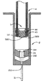
ゆえに、医療器材業者は医療人員が注射完成後に、ニードルに突き刺される危険をおかさずに、安全に尖ったニードルを妥当に収拾できる安全注射器の設計に尽力している。図2と図3は特許文献1に記載の安全注射器8であり、その外筒82の前端にはクランプ824が設けられ、ニードルホルダ830を挟持し、シールメンバ85は面取り部を具えたリブリング859によりプランジャー84前端に係止され、並びにバネ86の後ろ向きの引っ張り力を受け、操作員が注射完了後に、つづてプランジャー84を押して前進させて、外筒82前端のクランプ824を押し開いて、ニードルホルダ830とニードル831を釈放し、リブリング850も破壊して、これによりシールメンバ85がバネ86の引っ張り力を受けて後縮し、ニードルアセンブリ83を伴い一体にプランジャー84内に回収されるものとされる。
Therefore, medical equipment suppliers are dedicated to designing safe syringes that can reasonably pick up sharply pointed needles without risking the needle being pierced by the medical personnel after completing the injection. 2 and 3 show the safety syringe 8 described in Patent Document 1. A
しかし、もし1cc或いは2cc容量の注射器の場合、直径が数ミリしかない外筒82内に、外筒本体に沿ってクランプ824を後側より偏りなく前端まで挿入し、並びに正確な角度で精密に正確な位置に設置し、直径が更に小さいプランジャー84中に、更に後ろから前にバネ86を取り付け、後端をプランジャー84の後端底部に固定し、並びにバネ86を引き伸ばして前端をシールメンバ85に固定しなければならない。このように複雑で且つ精密な組立過程は、注射器価格を高騰させるため、実際の市場の要求する価格に符合しなくなる。
However, in the case of a syringe of 1 cc or 2 cc capacity, a
本発明の主要な目的は、プランジャー内部の減圧吸引作用により、ニードルアセンブリを自動的にプランジャー中に迅速に内臓できる安全注射器を提供することにある。 A primary object of the present invention is to provide a safety syringe that can automatically incorporate a needle assembly quickly into the plunger by a vacuum suction action inside the plunger.
本発明のもう一つの目的は、構造が簡単で且つ操作に便利であり、操作人員がニードルの突き刺しにより感染するのを防止できる安全注射器を提供することにある。 Another object of the present invention is to provide a safety syringe that is simple in structure and convenient for operation, and can prevent an operator from being infected by a needle stick.
請求項1の発明は、外筒であって、中空筒体を具え、前端開口と後端開口が形成され、前端開口の面積は後端開口の面積より小さく、結合シートが中空筒体の前端内に形成され、前端開口が結合シートを貫通する、上記外筒と、
フレキシブルなホルダ支持シートであって、外筒内に係止され且つ結合シート上に設けられ、該ホルダ支持シートに前後方向の貫通孔が形成された、上記フレキシブルなホルダ支持シートと、
ニードルアセンブリであって、後端に開孔を具えたニードルホルダ本体と、ニードルホルダ本体を貫通するニードルを具え、ニードルアセンブリは離脱可能に外筒前端内に組付けられ、ニードルホルダ本体はホルダ支持シートの貫通孔内に設置されて結合シートに当接し、ニードルは結合シートを貫通し、外筒前端開口より伸出する、上記ニードルアセンブリと、
プランジャーであって、前端と後端及びこの前端と後端の間に形成された中空筒体を具え、プランジャー前端に面積がニードルホルダ本体外径より大きい穿孔が形成され、プランジャー内壁面の前端近くに径方向収斂部が形成され、プランジャーが外筒内に設けられてプランジャー前端のホルダ支持シートに近い位置とプランジャー前端のホルダ支持シートより離れた位置の間で移動可能とされた、上記プランジャーと、
フレキシブルなシールメンバであって、プランジャーの径方向収斂部に圧接し、プランジャー前端の穿孔をシールし、プランジャーの筒体内に外部より低い気圧を保持させ、プランジャー前端がホルダ支持シートから所定の距離の位置に接近する時、シールメンバがニードルホルダ本体に結合し、プランジャーがホルダ支持シートを押圧し、該ホルダ支持シートを該結合シートに係止し、ニードルホルダ本体とホルダ支持シート間の結合を開放し、且つシールメンバがニードルホルダ本体の反作用力を受けて駆動されてシールメンバとプランジャーの結合が開放され、シールメンバとニードルアセンブリがプランジャーの筒体内の低圧吸引を受けてプランジャー内に縮入する、上記フレキシブルなシールメンバと、
を有することを特徴とする、安全注射器としている。
請求項2の発明は、請求項1記載の安全注射器において、シールメンバの弁部の接合部が延伸された側面に更にニードルホルダ本体の後端の開孔を塞ぐ突起が形成されたことを特徴とする、安全注射器としている。
請求項3の発明は、請求項1記載の安全注射器において、プランジャーの筒体の前端近くに外径が外筒内径より大きいフレキシブルな弁が設けられたことを特徴とする、安全注射器としている。
請求項4の発明は、請求項1記載の安全注射器において、シールメンバの弁部が中空弁体を呈することを特徴とする、安全注射器としている。
請求項5の発明は、請求項1記載の安全注射器において、径方向収斂部が外向きに拡張された前端を具えたことを特徴とする、安全注射器としている。
The invention according to claim 1, comprising an outer tube, comprising a medium superficial body, the front end opening and the rear opening is formed, the area of the front end opening smaller than the area of the rear end opening, bond sheet of the hollow cylinder The outer cylinder formed in the front end, and the front end opening penetrates the coupling sheet; and
A flexible holder support sheet, which is locked in an outer cylinder and provided on a coupling sheet, and wherein the holder support sheet has a through-hole in the front-rear direction ; and
A needle assembly, a needle holder body provided with a hole in the rear end, comprising a needle that penetrates a needle holder body, the needle assembly is releasably assembled to the outer cylinder front end, the needle holder body holder support The needle assembly installed in the through hole of the sheet and abutting on the coupling sheet, the needle penetrating the coupling sheet and extending from the front end opening of the outer cylinder; and
A plunger, comprising a front end and a rear end and a hollow cylindrical body formed between the front and rear ends, the area in the plunger front end is formed needle holder body outer diameter greater than the perforations, the plunger in A radial converging part is formed near the front end of the wall, and the plunger is provided in the outer cylinder, and can be moved between a position close to the holder support sheet at the front end of the plunger and a position away from the holder support sheet at the front end of the plunger And said plunger ,
A flexible seal member, pressed against the radially converging part of the flop flanger seals the perforation of the plunger front end, the tubular body of the plunger is held lower than the outside air pressure, the plunger front end from the holder support sheet When approaching a position of a predetermined distance, the seal member is coupled to the needle holder body, the plunger presses the holder support sheet, the holder support sheet is locked to the coupling sheet, and the needle holder body and the holder support sheet And the seal member is driven by the reaction force of the needle holder body to release the connection between the seal member and the plunger, and the seal member and the needle assembly receive low pressure suction in the plunger cylinder. you reduced entry into the plunger Te, and the flexible seal member,
The safety syringe is characterized by having the following .
According to a second aspect of the present invention, in the safety syringe according to the first aspect of the present invention, a protrusion for closing the opening at the rear end of the needle holder body is further formed on the side surface where the joint portion of the valve portion of the seal member is extended. And a safe syringe.
The invention according to
The invention according to
According to a fifth aspect of the present invention, in the safety syringe according to the first aspect of the present invention, the radial converging portion includes a front end that is expanded outward.
本発明は、プランジャー内部の減圧吸引作用により、ニードルアセンブリを自動的にプランジャー中に迅速に内臓できる安全注射器を提供している。 The present invention provides a safety syringe that can automatically incorporate a needle assembly into the plunger automatically by a vacuum suction action inside the plunger.
本発明はまた、構造が簡単で且つ操作に便利であり、操作人員がニードルの突き刺しにより感染するのを防止できる安全注射器を提供している。 The present invention also provides a safety syringe that is simple in structure and convenient for operation, and can prevent an operator from being infected by a needle stick.
本発明は一種の安全注射器を提供し、それは、外筒、フレキシブルなホルダ支持シート、ニードルアセンブリ、プランジャー、及びフレキシブルなシールメンバを具えている。外筒は中空筒体を具え、前端開口と後端開口が形成され、前端開口の面積は後端開口の面積より小さく、結合シートが中空筒体の前端内に形成され、前端開口は結合シートを貫通する。フレキシブルなホルダ支持シートは外筒内に係止され且つニードルホルダの上に設けられ、ホルダ支持シートに前後方向の貫通孔が設けられている。ニードルアセンブリは後端に開孔を具えたニードルホルダ本体と、ニードルホルダ本体を貫通するニードルを具え、ニードルアセンブリは離脱可能に外筒前端内に組付けられ、ニードルホルダ本体はホルダ支持シートの貫通孔内に設置されて結合シートに当接し、ニードルは結合シートを貫通し、外筒前端開口より伸出している。プランジャーは前端と後端及びこの前端と後端の間に形成された中空筒体を具え、プランジャー前端に面積がニードルホルダ本体外径より大きい穿孔が形成され、プランジャー内壁面の前端近くに径方向収斂部が形成され、プランジャーが外筒内に設けられ、プランジャー前端がホルダ支持シートに近い位置とプランジャー前端のホルダ支持シートより離れた位置の間で移動可能である。フレキシブルなシールメンバはプランジャーの径方向収斂部に圧接し、プランジャー前端の穿孔をシールし、プランジャーの筒体内に外部より低い気圧を保持させる。プランジャー前端のホルダ支持シートから所定の距離の位置に接近する時、シールメンバがニードルホルダ本体に結合し、プランジャーがホルダ支持シートを押圧し、ニードルホルダ本体とホルダ支持シート間の結合を開放し、且つシールメンバがニードルホルダ本体の反作用力を受けて、駆動されてシールメンバとプランジャーの結合を開放し、シールメンバとニードルアセンブリがプランジャーの筒体内の低圧吸引を受けてプランジャー内に縮入する。 The present invention provides a kind of safety syringe, which comprises an outer cylinder, a flexible holder support sheet, a needle assembly, a plunger, and a flexible seal member. The outer cylinder has a hollow cylinder, a front end opening and a rear end opening are formed, the area of the front end opening is smaller than the area of the rear end opening, the coupling sheet is formed in the front end of the hollow cylinder, and the front end opening is a coupling sheet To penetrate. The flexible holder support sheet is locked in the outer cylinder and provided on the needle holder, and the holder support sheet is provided with through holes in the front-rear direction. The needle assembly includes a needle holder main body having an opening at the rear end and a needle penetrating the needle holder main body. The needle assembly is removably assembled in the front end of the outer cylinder, and the needle holder main body penetrates the holder support sheet. It is installed in the hole and abuts on the coupling sheet, and the needle penetrates the coupling sheet and extends from the front end opening of the outer cylinder. The plunger has a front end and a rear end and a hollow cylinder formed between the front end and the rear end, and a hole having an area larger than the outer diameter of the needle holder body is formed at the front end of the plunger, near the front end of the inner wall surface of the plunger. And a plunger is provided in the outer cylinder, and the front end of the plunger is movable between a position close to the holder support sheet and a position away from the holder support sheet at the front end of the plunger. The flexible seal member is pressed against the radially convergent portion of the plunger, seals the perforation at the front end of the plunger, and maintains a lower air pressure inside the plunger cylinder than the outside. When approaching a position at a predetermined distance from the holder support sheet at the front end of the plunger, the seal member is coupled to the needle holder body, the plunger presses the holder support sheet, and the coupling between the needle holder body and the holder support sheet is released. The seal member receives the reaction force of the needle holder body and is driven to release the coupling between the seal member and the plunger, and the seal member and the needle assembly receive low-pressure suction in the plunger cylinder to receive the inside of the plunger. To fit.
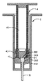
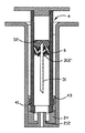
図4から図7に示されるように、本発明の第1実施例の安全注射器は、外筒2、外筒2前端に取り付けられたニードルアセンブリ3、離脱可能に外筒2内に組付けられたプランジャー4、及びプランジャー4前端をシールするためのフレキシブルなシールメンバ5を具えている。
As shown in FIGS. 4 to 7, the safety syringe according to the first embodiment of the present invention includes an
外筒2は中空筒体20を具え、筒体前端21と後端22に筒体20と連通する開口210、220が形成され、後端開口220の断面積はプランジャー4より僅かに大きく、プランジャー4が後端開口220より外筒2内に挿入される。結合シート212は筒体前端21内に設けられ、開口210が結合シート212を貫通する。結合シート212は筒体20と一体成形されるか或いは筒体前端21内の独立した部品とされる。前端開口210の断面積は後端開口220、筒体内径、プランジャー4の断面積のいずれよりも小さい。外筒2内壁面の内径と後端開口220はほぼ等しく、これにより外径がこの内径より僅かに大きいフレキシブルなホルダ支持シート24が外筒2の後端開口220より押し込まれ、外筒の筒体20内に係止され、外筒前端21と所定距離離れた位置とされ、フレキシブルなホルダ支持シート24中に、前後方向の貫通孔240が形成されている。
The
ニードルアセンブリ3は中空ニードルホルダ30と該ニードルホルダ30を貫通するニードル31を具え、ニードルアセンブリ3は離脱可能に外筒2のフレキシブルなホルダ支持シート24部分に組付けられ、ニードル31前端は結合シート212を通り外筒前端21の開口210より突出する。
The
プランジャー4は外筒2と同方向に延伸された中空筒体40を具え、該筒体40前端41に断面積がニードルホルダ30より大きい穿孔410が形成され、並びにシールメンバ5がプランジャー4前端に形成された穿孔410の内壁部分に設置され、プランジャーの筒体40がこれによりシール空間を形成する。注射薬剤を吸入したい時は、プランジャー4を外筒2の筒体20内で、プランジャー4の前端41をホルダ支持シート24に接近する位置より、エンドキャップ45により後ろ向きに引っ張る。注射時にはプランジャー4のエンドキャップ45を押圧し、プランジャー4を前向きにスライドさせて外筒2のホルダ支持シート24に接近する位置とし、プランジャー4前端41と外筒2のホルダ支持シート24間の距離を縮減し、薬剤を押し出す。当然、プランジャー4を外筒2内で押し引きする時の気密状態を保持するため、プランジャー4の筒体40に環状にフレキシブルなピストンメンバ43が組み合わされる。
The
本発明の第1実施例のニードルホルダ30を外筒2のホルダ支持シート24に結合させる構造は図5に示される。ニードルホルダ30は本体302と外径が本体302より大きい係止縁303を具え、ニードルホルダ30の後端に開口300が形成されている。ニードルホルダ本体302の断面積は外筒2前端の結合シート212の断面積に等しいかそれより僅かに大きい。ホルダ支持シート24中には内径がニードルホルダ本体302より僅かに小さい貫通孔240が形成され、ホルダ支持シート24の後側は斜面241を呈する。ニードルホルダ30がホルダ支持シート24の貫通孔240に挿入される時、ニードルホルダ本体302の外表面はホルダ支持シート24に形成された貫通孔240の壁面に径方向に挟持圧迫され、これによりニードルホルダ30がホルダ支持シート24部分に固定され、ニードルホルダ30の係止縁303はホルダ支持シート24の貫通孔240内にほぼ収容されて、ニードルホルダ本体302の後端とホルダ支持シート24の後側がこれにより斜面を呈する。ニードルホルダ30とホルダ支持シート24の結合後、外筒2の後端開口220に挿入され、更に外筒2の前端へと押し込まれる。この時、ニードルホルダ本体302の前端が外筒2前端21の結合シート212に当接する。ニードルホルダ本体302は外筒2前端の結合シート212に当接して両者が比較的大きな接触面積を形成することにより、ニードルアセンブリ3の外筒2の前端に固定される安定度が提供され、特に、注射器の容量が1cc或いは2ccである時、この結合シート212の設計は有効にニードルアセンブリ3と外筒2前端の結合の安定度を提供する。
A structure for coupling the
第1実施例中、シールメンバ5とプランジャー4の結合は、図6に示されるようであり、プランジャー4の内壁面に前端より後ろ向きに所定距離を延伸された径方向収斂部44が形成され、且つ本実施例では、プランジャーの後端42に穿孔420が形成され、プランジャー4が後端穿孔420をシールするエンドキャップ45を具えている。エンドキャップ45は基板452と基板452より延伸されてプランジャー4の筒体40に進入する頸部451を具え、頸部451の外径はプランジャー4の後端穿孔420の内径よりやや大きい。シールメンバ5は弁部52を具え、弁部52はプランジャー4の径方向収斂部44に挟持圧迫され、シールメンバ5がこれによりプランジャー4前端41近い位置に固定され、プランジャー4前端の穿孔410をシールする。その後、プランジャー4の筒体40に対する減圧により、その内部に外界気圧より低い低圧状態が形成され、気密用のエンドキャップ45がプランジャー後端開口420をシールする。プランジャー4前端の外壁にフレキシブルなピストンメンバ43が設けられ、その外径は外筒の筒体20内径よりやや大きい。
In the first embodiment, the coupling between the
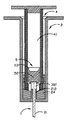
フレキシブルなシールメンバ5の接合部51は中空テーパ状を呈して弁部52より前向きに延伸され、外径が漸次後ろから前に縮減され、接合部51前端に至り、内径がニードルホルダの係止縁303よりやや小さい盲孔510が形成され、盲孔510中に、更に前向き突起520が形成されている。図7に示されるように、それはプランジャー4と外筒2を結合させ、図示される構造を形成する。図8に示されるように、プランジャーの前端41がホルダ支持シート24より所定の距離の位置に接近する時、接合部51に形成された盲孔510の端部がニードルホルダの係止縁303に嵌合し、突起520が更にニードルホルダ30の後端開口300をシールし、外筒2内の注射液が続けて押し出されるのを防止する。プランジャー4が続けてホルダ支持シート24を押圧して前進させる。ニードルホルダ30の本体302は外筒前端21の結合シート212の係止を受けて前進せず、これによりホルダ支持シート24がニードルホルダ30に対して前進でき、ホルダ支持シート24に形成された貫通孔240の内壁がニードルホルダ本体302を係止する位置より離脱し、前進して結合シート212をホルダ支持シート24の貫通孔240に進入させ、ニードルホルダ30とホルダ支持シート24間の結合がこれにより解除される。
The joint 51 of the
図9に示されるように、ニードルホルダ本体302はもともと外筒筒体前端21に形成された結合シート212の制圧を受け、ゆえにプランジャー4が後方の推力を受ける時、ニードルホルダ30はシールメンバ5を阻止して強制的にシールメンバ5が順調にプランジャー4と共に前進できないようにし、これによりシールメンバ5とプランジャー4の結合が解除され、プランジャーの筒体40内の低圧状態がこれにより釈放され、碗状気密部53の助けにより、空気が簡単には弁部52とプランジャー4の間の隙間よりプランジャー4の筒体40に流入せず、ゆえにプランジャー4の筒体40内の負圧吸引作用により、図10に示されるように、既に結合され一体となったニードルアセンブリ3とシールメンバ5が迅速に内縮し、並びにプランジャーの筒体40中に収容され、操作人員がニードル31に突き刺されて感染する危険が減らされる。
As shown in FIG. 9, the
図11から図15に示されるように、本発明の第2実施例の第1実施例と異なるところは、シールメンバ5の接合部51が比較的長く、且つプランジャーが外筒のホルダ支持シート24に接近する時、その接合部51が内縮して適宜ニードルアセンブリ3を挟持することにある。図11に示されるように、シールメンバ5は弁部52と接合部51を具え、弁部52の外径は径方向収斂部44の内径よりやや大きいため、径方向収斂部44が弁部52を挟持圧迫できる。径方向収斂部44の前端は図示されるようにやや外張し、ゆえに接合部51に未接触である。ゆえに、図12に示されるように、プランジャー4がホルダ支持シート24に接近する時、接合部51はニードルホルダ30とホルダ支持シート24に接触し、押圧されて湾曲する。プランジャー4が続けてホルダ支持シート24を押圧して前進させる時、図13に示されるように、続けて押圧を受ける接合部51が、径方向収斂部44の外拡の構造により発生する空間により、プランジャー4とホルダ支持シート24が緊密に接触する時に、押圧され径方向収斂部44の間に収容される。このとき、接合部51の前端の突起520はニードルホルダ本体302の後端開口300に圧入されて開口300を封じ、並びに接合部51がニードルホルダの係止縁303の押圧を受けて外向きに拡張し、ニードルホルダの係止縁303を係止し、これによりシールメンバ5とニードルアセンブリ3が一体に結合される。図14に示されるように、プランジャー4が続けて後方推力を受ける時、ニードルホルダ30がシールメンバ5を阻止し、強制的にシールメンバ5がプランジャー4に伴い前進できないようにし、シールメンバ5とプランジャー4の結合を解除し、これによりプランジャー4の筒体40内の負圧吸引作用下で、既に結合され一体とされたニードルアセンブリ3とシールメンバ5が迅速に内縮し、並びにプランジャーの筒体40中に収容される。
As shown in FIGS. 11 to 15, the second embodiment of the present invention is different from the first embodiment in that the joint 51 of the
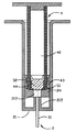
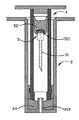
当然、本発明の技術に習熟する者であれば容易に理解できることであるが、ホルダ支持シートの構造、シールメンバ、ニードルホルダの対応する構造、シールメンバのプランジャー内への組付け方式は上述の実施例に限定されるものではなく、例えば図16から図19に示される本発明の第3実施例(同じ部品は同じ符号で表示されており、説明は省略する)では、穿孔60を具えた逆U形ゴムメンバ6がホルダ支持シート24の貫通孔240内に放置され、並びにホルダ支持シート24とニードルホルダ本体302’の間に挟持され、これにより逆U形のゴムメンバ6の底面がホルダ支持シート24の後側と結合され、ニードル31出口が逆U形ゴムメンバ6より突出し、並びに逆U形のゴムメンバ6の外径がプランジャー4内径よりやや大きくされている。ニードル31後端はニードルホルダ本体302’より突出し、並びに逆U形のゴムメンバ6の穿孔60を通過し、穿孔60より突出する。逆U形のゴムメンバ6の穿孔60内径はニードル31外径よりやや小さく、これによりニードル31が逆U形のゴムメンバ6に挟持される。シールメンバ5の対応構造もまたこれに合わせて変化し、そのうち、弁部52の前端520’は円弧面を呈するが、円弧面に限定されるわけではなく、緊密に逆U形のゴムメンバ6の底面に当接する。図17に示されるように、プランジャー4が外筒2前端から所定の距離に接近する時、シールメンバ5の前端520’が逆U形のゴムメンバ6の底面に接合し、並びにニードル31がシールメンバの弁部52に突き刺さり針孔を塞ぎ、並びにニードルアセンブリ3、逆U形のゴムメンバ6及びシールメンバ5が一体に結合される。図18に示されるように、続けてプランジャー4が押されると、ホルダ支持シート24が押圧を受けて下向きにスライドし、同時にニードルホルダ本体302が結合シート212の阻止を受け、反作用力を発生してシールメンバ5をプランジャー4前端開口より押し離してプランジャー4内に進入し、この時、シールメンバ5と結合された逆U形のゴムメンバ6もまたプランジャー4前端開口内に進入し、更にプランジャー4が押されると、逆U形のゴムメンバ6がプランジャー4内部に進入し、これによりピストン機能が形成される。プランジャー4内部の低圧作用を受け、一体に結合されたシールメンバ5、逆U形のゴムメンバ6及びニードルアセンブリ3がプランジャー4内に吸入される。図19に示されるように、プランジャー4内の低圧により、結合され一体とされたニードルアセンブリ3、逆U形のゴムメンバ6及びシールメンバ5がプランジャーの筒体40中に吸入される。
Of course, those skilled in the art of the present invention can easily understand, but the structure of the holder support sheet, the seal member, the corresponding structure of the needle holder, and the assembly method of the seal member in the plunger are described above. In the third embodiment of the present invention shown in FIGS. 16 to 19 (the same parts are denoted by the same reference numerals and the description thereof is omitted), for example, the
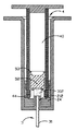
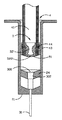
図20に示されるように、本発明の第4実施例の第3実施例と異なるところは、外筒2の前端21の構造の変化にあり、外筒の前端21に開口210’が形成され、それはニードル31に対応し、ニードル31が外筒前端21より伸出させられている。プランジャー4がホルダ支持シート24から所定の距離の位置に接近する時、ニードル31後端がシールメンバ5の前端に突き刺さり、シールメンバ5、逆U形のゴムメンバ6及びニードルアセンブリ3が一体に結合される。プランジャー4が続けてホルダ支持シート24を押して前進する時、ニードルホルダ本体302の前段が外筒2の前端開口210’の阻止を受けて前進不能となり、これによりホルダ支持シート24がニードルホルダ30に対して前進し、ホルダ支持シートの貫通孔240内壁が逆U形のゴムメンバ6及びニードルホルダ本体302の係止位置より離脱し、前進してニードルホルダ本体302の前段部分に至り、逆U形のゴムメンバ6及びニードルホルダ30及びホルダ支持シート24の結合がこれにより解除される。ニードルホルダ本体302の前段は外筒の前端開口210の制圧を受けるため、プランジャー4が後方推力を受ける時、ニードルホルダ30がシールメンバ5を阻止し、強制的にシールメンバ5がプランジャー4に伴い前進しないようにし、シールメンバ5とプランジャー4の結合を解除し、プランジャー4の筒体40内の負圧作用により、既に一体に結合されたシールメンバ5、逆U形のゴムメンバ6、及びニードルアセンブリ3を迅速に内縮させ、プランジャーの筒体40中に収容する。
As shown in FIG. 20, the fourth embodiment of the present invention differs from the third embodiment in the change in the structure of the
図21から図24は本発明の第5実施例であり、その第1実施例と異なるところは、シールメンバ5の構造変化にあり、図21に示されるように、シールメンバ5の接合部51の前端に形成された盲孔510’内に、楕円形の弁体521が設けられている。図22に示されるように、プランジャー4の前端41がホルダ支持シート24に所定の距離接近する時、接合部51に形成された盲孔510’の端部がニードルホルダの係止縁303に嵌合し、楕円形の弁体521が更にニードルホルダ30の後端開口300を封じ、外筒2内の注射液の持続押出を防止し、接合部51はニードルホルダ30の係止縁303に係止され、これによりシールメンバ5とニードルアセンブリ3が一体に結合され、プランジャー4が続けてホルダ支持シート24を押して前進する。図23に示されるように、ニードルホルダ本体302が外筒2前端の結合シート212の阻止を受けて前進不能となることで、ホルダ支持シート24がニードルホルダ30に対して前進し、ホルダ支持シート24に形成された貫通孔240の内壁がニードルホルダ本体302を係止する位置より離脱し、前進して外筒の前端21に至り、ニードルホルダ30とホルダ支持シート24間の結合がこれにより解除される。図24に示されるように、ニードルホルダ本体302はもともと外筒前端の結合シート212の制圧を受けるため、プランジャー4が後方の推力を受ける時、ニードルホルダ30がシールメンバ5を阻止し、強制的にシールメンバ5をプランジャー4に伴い前進しないようにし、こうしてシールメンバ5とプランジャー4の結合が解除され、ゆえに、プランジャー4の筒体40内の負圧吸引作用により、既に結合されて一体とされたニードルアセンブリ3、楕円形の弁体521及びシールメンバ5が迅速に内縮し、並びにプランジャーの筒体40内に収容される。
FIGS. 21 to 24 show a fifth embodiment of the present invention. The difference from the first embodiment is in the structural change of the
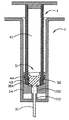
図25は本発明の第6実施例を示し、その第5実施例との違いは、外筒2の前端21の構造の変化にあり、外筒の前端21に開口210が形成され、それはニードル31に対応し、ニードル31が外筒前端21より突出する。プランジャー4の前端41がホルダ支持シート24から所定の距離に到る時、接合部51に形成された盲孔510’の端部がニードルホルダ30の係止縁303に嵌合し、楕円形の弁体521が更にニードルホルダ30の後端開口300を封じ、外筒2内の注射液が続いて押し出されるのを防止し、プランジャー4が続けてホルダ支持シート24を押して前進する。プランジャー4がホルダ支持シート24を押して前進する時、ニードルホルダ本体302の前段が外筒2の前端開口210’の阻止を受けて前進不能であるため、ホルダ支持シート24がニードルホルダ30に対して前進し、ホルダ支持シート24の貫通孔240内壁がニードルホルダ本体302を係止する位置より離脱し、前進してニードルホルダ本体302前段部分に至り、ニードルホルダ30とホルダ支持シート24の結合がこれにより解除される。ニードルホルダ本体302の前段はもともと外筒の前端開口210の制圧を受けるため、プランジャー4が後方推力を受ける時、ニードルホルダ30が楕円形の弁体521及びシールメンバ5を阻止し、強制的に両者をプランジャー4に伴い前進不能とし、シールメンバ5とプランジャー4の結合を強制的に解除させ、プランジャー4の筒体40内の負圧作用下で、既に結合され一体とされた弁体521とニードルアセンブリ3を迅速に内縮させ、並びに筒体40中に収容する。
FIG. 25 shows a sixth embodiment of the present invention, which is different from the fifth embodiment in the change in the structure of the
図26、27は本発明の第7実施例を示し、その第5実施例との違いはシールメンバ5の構造変化にあり、図26に示されるように、シールメンバ5は中空弁部52’を具え、接合部51は中空テーパ状を呈して中空弁部52’より前向きに延伸され、外径が後ろから前に漸減され、接合部51前端に、内径がニードルホルダの係止縁303より小さい盲孔510’が形成され、中空弁部52’に更に前向きに突起520’が盲孔510’中において形成されている。図27に示されるように、プランジャー4の前端41がホルダ支持シート24から所定の距離に到る時、接合部51に形成された盲孔510’の端部がニードルホルダ30の係止縁303に嵌合し、突起520’が更にニードルホルダ30の後端開口300を封じ、外筒2内の注射液が続いて押し出されるのを防止し、プランジャー4が続けてホルダ支持シート24を押して前進する。プランジャー4がホルダ支持シート24を押して前進する時、ニードルホルダ本体302の前段が外筒2の前端結合シート212の阻止を受けて受けて前進不能であるため、ホルダ支持シート24がニードルホルダ30に対して前進し、ホルダ支持シート24の貫通孔240内壁がニードルホルダ本体302を係止する位置より離脱し、前進して外筒の前端21に至り、ニードルホルダ30とホルダ支持シート24の結合がこれにより解除される。ニードルホルダ本体302の前段はもともと外筒の前端の結合シート212の制圧を受けるため、プランジャー4が後方推力を受ける時、ニードルホルダ30がシールメンバ5を阻止し、強制的に両者をプランジャー4に伴い前進不能とし、シールメンバ5とプランジャー4の結合を強制的に解除させ、プランジャー4の筒体40内の負圧作用下で、既に結合され一体とされたニードルアセンブリ3とシールメンバ5を迅速に内縮させ、並びに筒体40中に収容する。
26 and 27 show a seventh embodiment of the present invention. The difference from the fifth embodiment is the structural change of the
図28は本発明の第8実施例を示し、その第7実施例との違いは外筒2の前端21の構造変化にあり、外筒2の前端21に開口210’が形成されてニードル31に対応し、ニードル31が外筒の前端21より伸出している。プランジャー4がホルダ支持シート24より所定の距離に接近する時、接合部51に形成された盲孔510’の端部がニードルホルダ30の係止縁303に嵌合し、突起521’が更にニードルホルダ30の後端開口300を封じ、外筒2内の注射液が続いて押し出されるのを防止し、プランジャー4が続けてホルダ支持シート24を押して前進する。プランジャー4がホルダ支持シート24を押して前進する時、ニードルホルダ本体302の前段が外筒2の前端開口210’の阻止を受けて前進不能となり、これにより、ホルダ支持シート24がニードルホルダ30に対して前進し、ホルダ支持シート24の貫通孔240内壁がニードルホルダ本体302を係止する位置より離脱し、前進してニードルホルダ本体302の前段部分に至り、ニードルホルダ30とホルダ支持シート24の結合がこれにより解除される。ニードルホルダ本体302の前段はもともと外筒の前端の開口210の制圧を受けるため、プランジャー4が後方推力を受ける時、ニードルホルダ30がシールメンバ5を阻止し、強制的にそれをプランジャー4に伴い前進不能とし、シールメンバ5とプランジャー4の結合を強制的に解除させ、プランジャー4の筒体40内の負圧作用下で、既に結合され一体とされたニードルアセンブリ3とシールメンバ5を迅速に内縮させ、並びに筒体40中に収容する。
FIG. 28 shows an eighth embodiment of the present invention. The difference from the seventh embodiment lies in the structural change of the
図29、30、31は本発明の第9実施例を示し、その第1実施例との違いはニードルアセンブリ3とシールメンバ5の構造変化にあり、そのうち、ニードルアセンブリ3は、中空のニードルホルダ30と該ニードルホルダ30に通されたニードル31を具え、ニードルホルダ30は本体302と一対のフック304を具え、該フック304は径方向にあって対向するように本体302周囲に上向きに形成されている。図30に示されるように、シールメンバ5の弁部52の前端522は曲面を具え、並びにニードルホルダ30の一対のフック304との嵌合に供される環状開口523が弁部の前端522に形成されている。図31に示されるように、プランジャー4がホルダ支持シート24より所定の距離に接近する時、ニードルホルダ30の一対のフック304がシールメンバ5の弁部52の環状開口523に嵌入し、これによりニードルホルダ30とシールメンバ5が一体に結合され、弁部前端522が更にニードルホルダ30の後端開口300を塞ぎ、外筒2内の注射液が続いて押し出されるのを防止し、プランジャー4が続けてホルダ支持シート24を押して前進する。ニードルホルダ本体302の前段が外筒2の前端の結合シート212の阻止を受けて前進不能となり、これにより、ホルダ支持シート24がニードルホルダ30に対して前進し、ホルダ支持シート24の貫通孔240内壁がニードルホルダ本体302を係止する位置より離脱し、前進して外筒の前端21に到ると、ニードルホルダ30とホルダ支持シート24の結合がこれにより解除される。ニードルホルダ本体302は外筒の前端の結合シート212の制圧を受けるため、プランジャー4が後方推力を受ける時、ニードルホルダ30がシールメンバ5を阻止し、強制的にそれをプランジャー4に伴い前進不能とし、シールメンバ5とプランジャー4の結合を強制的に解除させ、プランジャー4の筒体40内の負圧作用下で、既に結合され一体とされたニードルアセンブリ3とシールメンバ5が迅速に内縮し、並びに筒体40中に収容される。
29, 30, and 31 show a ninth embodiment of the present invention, which is different from the first embodiment in the structural changes of the
図32は本発明の第10実施例を示し、その第9実施例との違いは外筒2の前端21の構造の変化にあり、外筒の前端21に開口210’が形成され、それはニードル31に対応し、ニードル31が外筒前端21より伸出させられている。プランジャー4がホルダ支持シート24より所定の距離に接近する時、ニードルホルダ30の一対のフック304がシールメンバ5の弁部52の前端522の環状開口523に嵌入し、これによりニードルホルダ30とシールメンバ5が一体に結合され、弁部前端522が更にニードルホルダ30の後端開口300を塞ぎ、外筒2内の注射液が続いて押し出されるのを防止し、プランジャー4が続けてホルダ支持シート24を押して前進する。プランジャー4が続けてホルダ支持シート24を押して前進する時、ニードルホルダ本体302の前段が外筒2の前端の開口210’の阻止を受けて前進不能となり、これにより、ホルダ支持シート24がニードルホルダ30に対して前進し、ホルダ支持シート24の貫通孔240内壁がニードルホルダ本体302を係止する位置より離脱し、前進してニードルホルダ本体302の前段部分に到ると、ニードルホルダ30とホルダ支持シート24の結合がこれにより解除される。ニードルホルダ本体302は外筒の前端の開口210の制圧を受けるため、プランジャー4が後方推力を受ける時、ニードルホルダ30がシールメンバ5を阻止し、強制的にそれをプランジャー4に伴い前進不能とし、シールメンバ5とプランジャー4の結合を強制的に解除させ、プランジャー4の筒体40内の負圧作用下で、既に結合され一体とされたニードルアセンブリ3とシールメンバ5が迅速に内縮し、並びに筒体40中に収容される。
FIG. 32 shows a tenth embodiment of the present invention, which is different from the ninth embodiment in the change in the structure of the
以上から本発明の安全注射器は、簡単な構造の組合せにより、有効に安全注射器の製造コストを減らし、並びに使用者の安全性を保障する。 As described above, the safety syringe of the present invention effectively reduces the manufacturing cost of the safety syringe and guarantees the safety of the user by a combination of simple structures.
以上は本発明の具体的実施例の説明であって本発明の請求範囲を制限するものではなく、本発明に記載の精神下で完成されて等しい効果を有する改変或いは修飾は、いずれも本発明の請求範囲に属するものとする。 The foregoing is a description of specific embodiments of the present invention, and is not intended to limit the scope of the present invention. Any modification or modification completed in the spirit described in the present invention and having the same effect will be described in the present invention. Shall belong to the claims.
2 外筒 3 ニードルアセンブリ
4 プランジャー 5 シールメンバ
6 逆U形のゴムメンバ 7 注射器
8 安全注射器 20 筒体
21 前端 22 後端
24 ホルダ支持シート 30 ニードルホルダ
31 ニードル 40 筒体
41 前端 42 後端
43 ピストンメンバ 44 径方向収斂部
45 エンドキャップ 51 接合部
52 弁部 52’ 弁部
53 気密部 60 穿孔
72 外筒 73 ニードルアセンブリ
74 プランジャー 82 外筒
83 ニードルアセンブリ 84 プランジャー
85 シールメンバ 86 バネ
210、210’ 開口
212 結合シート 220 開口
240 貫通孔 241 斜面
300 開口 301 前段
302、302’ ニードルホルダ本体
303 係止縁 304 フック
410、420 穿孔 451 頸部
452 基板 510、510’ 盲孔
520 突起 520’ 前端
521 弁体 522 前端
523 環状開口 724 開口
730 ニードルホルダ 731 ニードル
743 ゴム弁 824 クランプ
830 ニードルホルダ 831 ニードル
2
Claims (5)
フレキシブルなホルダ支持シートであって、外筒内に係止され且つ結合シート上に設けられ、該ホルダ支持シートに前後方向の貫通孔が形成された、上記フレキシブルなホルダ支持シートと、
ニードルアセンブリであって、後端に開孔を具えたニードルホルダ本体と、ニードルホルダ本体を貫通するニードルを具え、ニードルアセンブリは離脱可能に外筒前端内に組付けられ、ニードルホルダ本体はホルダ支持シートの貫通孔内に設置されて結合シートに当接し、ニードルは結合シートを貫通し、外筒前端開口より伸出する、上記ニードルアセンブリと、
プランジャーであって、前端と後端及びこの前端と後端の間に形成された中空筒体を具え、プランジャー前端に面積がニードルホルダ本体外径より大きい穿孔が形成され、プランジャー内壁面の前端近くに径方向収斂部が形成され、プランジャーが外筒内に設けられてプランジャー前端のホルダ支持シートに近い位置とプランジャー前端のホルダ支持シートより離れた位置の間で移動可能とされた、上記プランジャーと、
フレキシブルなシールメンバであって、プランジャーの径方向収斂部に圧接し、プランジャー前端の穿孔をシールし、プランジャーの筒体内に外部より低い気圧を保持させ、プランジャー前端がホルダ支持シートから所定の距離の位置に接近する時、シールメンバがニードルホルダ本体に結合し、プランジャーがホルダ支持シートを押圧し、該ホルダ支持シートを該結合シートに係止し、ニードルホルダ本体とホルダ支持シート間の結合を開放し、且つシールメンバがニードルホルダ本体の反作用力を受けて駆動されてシールメンバとプランジャーの結合が開放され、シールメンバとニードルアセンブリがプランジャーの筒体内の低圧吸引を受けてプランジャー内に縮入する、上記フレキシブルなシールメンバと、
を有することを特徴とする、安全注射器。 A outer cylinder, comprising a medium superficial body, is the front end opening and a rear opening is formed, the area of the front end opening is smaller than the area of the rear end opening, coupling sheet is formed in the front end of the hollow cylinder, the front end The outer cylinder through which the opening penetrates the coupling sheet; and
A flexible holder support sheet, which is locked in an outer cylinder and provided on a coupling sheet, and wherein the holder support sheet has a through-hole in the front-rear direction ; and
A needle assembly, a needle holder body provided with a hole in the rear end, comprising a needle that penetrates a needle holder body, the needle assembly is releasably assembled to the outer cylinder front end, the needle holder body holder support The needle assembly installed in the through hole of the sheet and abutting on the coupling sheet, the needle penetrating the coupling sheet and extending from the front end opening of the outer cylinder; and
A plunger, comprising a front end and a rear end and a hollow cylindrical body formed between the front and rear ends, the area in the plunger front end is formed needle holder body outer diameter greater than the perforations, the plunger in A radial converging part is formed near the front end of the wall, and the plunger is provided in the outer cylinder, and can be moved between a position close to the holder support sheet at the front end of the plunger and a position away from the holder support sheet at the front end of the plunger And said plunger ,
A flexible seal member, pressed against the radially converging part of the flop flanger seals the perforation of the plunger front end, the tubular body of the plunger is held lower than the outside air pressure, the plunger front end from the holder support sheet When approaching a position of a predetermined distance, the seal member is coupled to the needle holder body, the plunger presses the holder support sheet, the holder support sheet is locked to the coupling sheet, and the needle holder body and the holder support sheet And the seal member is driven by the reaction force of the needle holder body to release the connection between the seal member and the plunger, and the seal member and the needle assembly receive low pressure suction in the plunger cylinder. you reduced entry into the plunger Te, and the flexible seal member,
A safety syringe characterized by comprising:
2. The safety syringe according to claim 1, further comprising a front end having a radially convergent portion extended outward.
Applications Claiming Priority (1)
| Application Number | Priority Date | Filing Date | Title |
|---|---|---|---|
| CNB2003101232972A CN100382856C (en) | 2003-12-22 | 2003-12-22 | Safe syringe |
Publications (2)
| Publication Number | Publication Date |
|---|---|
| JP2005177467A JP2005177467A (en) | 2005-07-07 |
| JP4253295B2 true JP4253295B2 (en) | 2009-04-08 |
Family
ID=34529400
Family Applications (1)
| Application Number | Title | Priority Date | Filing Date |
|---|---|---|---|
| JP2004341642A Expired - Fee Related JP4253295B2 (en) | 2003-12-22 | 2004-11-26 | Safety syringe |
Country Status (4)
| Country | Link |
|---|---|
| EP (1) | EP1547634B1 (en) |
| JP (1) | JP4253295B2 (en) |
| CN (1) | CN100382856C (en) |
| DE (1) | DE602004022010D1 (en) |
Families Citing this family (10)
| Publication number | Priority date | Publication date | Assignee | Title |
|---|---|---|---|---|
| CN102085405B (en) * | 2006-03-13 | 2012-10-31 | 医疗卫士有限公司 | A needle containing medical device with variable locking to needle holder |
| CN2877738Y (en) * | 2006-03-28 | 2007-03-14 | 李健全 | Disposable completely self-destroyable safety syringe |
| AU2007231844B2 (en) * | 2006-11-06 | 2013-05-30 | Clayson, Simon Paul Mr | Retractable Syringe |
| US8814827B2 (en) | 2006-11-06 | 2014-08-26 | Simon Paul Clayson | Retractable syringe |
| WO2010100243A1 (en) * | 2009-03-05 | 2010-09-10 | Sanofi-Aventis Deutschland Gmbh | Needle unit |
| AU2010220255B2 (en) * | 2009-03-05 | 2014-09-04 | Sanofi-Aventis Deutschland Gmbh | Drug delivery device with retractable needle |
| WO2010100240A1 (en) * | 2009-03-05 | 2010-09-10 | Sanofi-Aventis Deutschland Gmbh | Needle assembly |
| EP2498843A4 (en) * | 2009-11-11 | 2013-10-09 | Unitract Syringe Pty Ltd | Clinical syringe |
| TWI527602B (en) * | 2011-11-07 | 2016-04-01 | Fan Xiao Yi | Ordinary safety syringes |
| US11298467B2 (en) | 2019-02-27 | 2022-04-12 | Retractable Technologies, Inc. | Syringe with multifunctional needle holder and retainer ring assembly |
Family Cites Families (5)
| Publication number | Priority date | Publication date | Assignee | Title |
|---|---|---|---|---|
| US6221055B1 (en) * | 1998-03-04 | 2001-04-24 | Retractable Technologies, Inc. | Retractable dental syringe |
| CN100358594C (en) * | 2000-01-04 | 2008-01-02 | 贝克顿迪肯森公司 | Retractable needle syringe |
| US7074207B2 (en) * | 2001-08-17 | 2006-07-11 | Chung-Yu Yang | Safety syringe |
| US20030212371A1 (en) * | 2002-05-10 | 2003-11-13 | Martin E. Smith | Disposable safety syringe |
| WO2004105842A1 (en) * | 2003-05-27 | 2004-12-09 | Nmt Group Plc | Syringes with restrictor |
-
2003
- 2003-12-22 CN CNB2003101232972A patent/CN100382856C/en not_active Expired - Fee Related
-
2004
- 2004-11-18 DE DE200460022010 patent/DE602004022010D1/en active Active
- 2004-11-18 EP EP20040105886 patent/EP1547634B1/en not_active Not-in-force
- 2004-11-26 JP JP2004341642A patent/JP4253295B2/en not_active Expired - Fee Related
Also Published As
| Publication number | Publication date |
|---|---|
| CN1631460A (en) | 2005-06-29 |
| EP1547634A1 (en) | 2005-06-29 |
| JP2005177467A (en) | 2005-07-07 |
| CN100382856C (en) | 2008-04-23 |
| DE602004022010D1 (en) | 2009-08-27 |
| EP1547634B1 (en) | 2009-07-15 |
Similar Documents
| Publication | Publication Date | Title |
|---|---|---|
| US7410478B2 (en) | Safety syringe with needle retracting mechanism | |
| EP2764885B1 (en) | Indwelling catheter | |
| JP4698838B2 (en) | Retractable needle syringe | |
| JP2644568B2 (en) | Disposable hypodermic syringe | |
| EP2000164A1 (en) | Self-destroying disposable syringe and self-destroying method thereof | |
| EP1842570B1 (en) | A self destruction disposable syringe | |
| JP4253295B2 (en) | Safety syringe | |
| MXPA06004718A (en) | Self-locking safety disposable syringe with needle protection after use. | |
| US6193687B1 (en) | Safety hypodermic syringe | |
| US7993307B2 (en) | Safe medical syringe with an automatic slowly retractable needle | |
| US8034024B2 (en) | Needle containing medical device with variable locking to needle holder | |
| JP2005329220A (en) | Disposable syringe | |
| JP2006526443A (en) | Disposable syringe | |
| US6432082B1 (en) | Safety syringe | |
| US20030199834A1 (en) | Self-locking disposable safety syringe | |
| WO2009097743A1 (en) | Core rod locking device for safety syringe | |
| US7074207B2 (en) | Safety syringe | |
| JPH05503649A (en) | syringe with retractable needle | |
| WO2007028296A1 (en) | A safety syringe | |
| JP2004188199A (en) | Safe syringe | |
| EP1442763A1 (en) | Safety syringe with needle retracted by vacuum | |
| EP1726321A2 (en) | Safety hypodermic syringe | |
| JP3106380U (en) | Automatic needle retractable safety syringe | |
| JP2759909B2 (en) | Syringe | |
| CN101219252B (en) | Safety tube center needle for insertion of intravenous injection catheter |
Legal Events
| Date | Code | Title | Description |
|---|---|---|---|
| A131 | Notification of reasons for refusal |
Free format text: JAPANESE INTERMEDIATE CODE: A131 Effective date: 20080205 |
|
| A711 | Notification of change in applicant |
Free format text: JAPANESE INTERMEDIATE CODE: A711 Effective date: 20080225 |
|
| A521 | Written amendment |
Free format text: JAPANESE INTERMEDIATE CODE: A821 Effective date: 20080225 |
|
| A601 | Written request for extension of time |
Free format text: JAPANESE INTERMEDIATE CODE: A601 Effective date: 20080507 |
|
| A602 | Written permission of extension of time |
Free format text: JAPANESE INTERMEDIATE CODE: A602 Effective date: 20080512 |
|
| A521 | Written amendment |
Free format text: JAPANESE INTERMEDIATE CODE: A523 Effective date: 20080604 |
|
| TRDD | Decision of grant or rejection written | ||
| A01 | Written decision to grant a patent or to grant a registration (utility model) |
Free format text: JAPANESE INTERMEDIATE CODE: A01 Effective date: 20090113 |
|
| A01 | Written decision to grant a patent or to grant a registration (utility model) |
Free format text: JAPANESE INTERMEDIATE CODE: A01 |
|
| A61 | First payment of annual fees (during grant procedure) |
Free format text: JAPANESE INTERMEDIATE CODE: A61 Effective date: 20090123 |
|
| R150 | Certificate of patent or registration of utility model |
Free format text: JAPANESE INTERMEDIATE CODE: R150 |
|
| FPAY | Renewal fee payment (event date is renewal date of database) |
Free format text: PAYMENT UNTIL: 20120130 Year of fee payment: 3 |
|
| FPAY | Renewal fee payment (event date is renewal date of database) |
Free format text: PAYMENT UNTIL: 20120130 Year of fee payment: 3 |
|
| FPAY | Renewal fee payment (event date is renewal date of database) |
Free format text: PAYMENT UNTIL: 20150130 Year of fee payment: 6 |
|
| R250 | Receipt of annual fees |
Free format text: JAPANESE INTERMEDIATE CODE: R250 |
|
| LAPS | Cancellation because of no payment of annual fees |