EP1442762A2 - Prefilled syringe and production method for a barrel thereof - Google Patents
Prefilled syringe and production method for a barrel thereof Download PDFInfo
- Publication number
- EP1442762A2 EP1442762A2 EP04001191A EP04001191A EP1442762A2 EP 1442762 A2 EP1442762 A2 EP 1442762A2 EP 04001191 A EP04001191 A EP 04001191A EP 04001191 A EP04001191 A EP 04001191A EP 1442762 A2 EP1442762 A2 EP 1442762A2
- Authority
- EP
- European Patent Office
- Prior art keywords
- barrel
- barrier property
- resin
- luer tip
- prefilled syringe
- Prior art date
- Legal status (The legal status is an assumption and is not a legal conclusion. Google has not performed a legal analysis and makes no representation as to the accuracy of the status listed.)
- Granted
Links
Images



Classifications
-
- B—PERFORMING OPERATIONS; TRANSPORTING
- B29—WORKING OF PLASTICS; WORKING OF SUBSTANCES IN A PLASTIC STATE IN GENERAL
- B29C—SHAPING OR JOINING OF PLASTICS; SHAPING OF MATERIAL IN A PLASTIC STATE, NOT OTHERWISE PROVIDED FOR; AFTER-TREATMENT OF THE SHAPED PRODUCTS, e.g. REPAIRING
- B29C45/00—Injection moulding, i.e. forcing the required volume of moulding material through a nozzle into a closed mould; Apparatus therefor
- B29C45/16—Making multilayered or multicoloured articles
- B29C45/1603—Multi-way nozzles specially adapted therefor
-
- A—HUMAN NECESSITIES
- A61—MEDICAL OR VETERINARY SCIENCE; HYGIENE
- A61M—DEVICES FOR INTRODUCING MEDIA INTO, OR ONTO, THE BODY; DEVICES FOR TRANSDUCING BODY MEDIA OR FOR TAKING MEDIA FROM THE BODY; DEVICES FOR PRODUCING OR ENDING SLEEP OR STUPOR
- A61M5/00—Devices for bringing media into the body in a subcutaneous, intra-vascular or intramuscular way; Accessories therefor, e.g. filling or cleaning devices, arm-rests
- A61M5/178—Syringes
- A61M5/31—Details
- A61M5/3129—Syringe barrels
-
- B—PERFORMING OPERATIONS; TRANSPORTING
- B29—WORKING OF PLASTICS; WORKING OF SUBSTANCES IN A PLASTIC STATE IN GENERAL
- B29C—SHAPING OR JOINING OF PLASTICS; SHAPING OF MATERIAL IN A PLASTIC STATE, NOT OTHERWISE PROVIDED FOR; AFTER-TREATMENT OF THE SHAPED PRODUCTS, e.g. REPAIRING
- B29C45/00—Injection moulding, i.e. forcing the required volume of moulding material through a nozzle into a closed mould; Apparatus therefor
- B29C45/16—Making multilayered or multicoloured articles
- B29C45/1642—Making multilayered or multicoloured articles having a "sandwich" structure
-
- B—PERFORMING OPERATIONS; TRANSPORTING
- B29—WORKING OF PLASTICS; WORKING OF SUBSTANCES IN A PLASTIC STATE IN GENERAL
- B29K—INDEXING SCHEME ASSOCIATED WITH SUBCLASSES B29B, B29C OR B29D, RELATING TO MOULDING MATERIALS OR TO MATERIALS FOR MOULDS, REINFORCEMENTS, FILLERS OR PREFORMED PARTS, e.g. INSERTS
- B29K2023/00—Use of polyalkenes or derivatives thereof as moulding material
-
- B—PERFORMING OPERATIONS; TRANSPORTING
- B29—WORKING OF PLASTICS; WORKING OF SUBSTANCES IN A PLASTIC STATE IN GENERAL
- B29K—INDEXING SCHEME ASSOCIATED WITH SUBCLASSES B29B, B29C OR B29D, RELATING TO MOULDING MATERIALS OR TO MATERIALS FOR MOULDS, REINFORCEMENTS, FILLERS OR PREFORMED PARTS, e.g. INSERTS
- B29K2023/00—Use of polyalkenes or derivatives thereof as moulding material
- B29K2023/04—Polymers of ethylene
- B29K2023/08—Copolymers of ethylene
- B29K2023/086—EVOH, i.e. ethylene vinyl alcohol copolymer
-
- B—PERFORMING OPERATIONS; TRANSPORTING
- B29—WORKING OF PLASTICS; WORKING OF SUBSTANCES IN A PLASTIC STATE IN GENERAL
- B29K—INDEXING SCHEME ASSOCIATED WITH SUBCLASSES B29B, B29C OR B29D, RELATING TO MOULDING MATERIALS OR TO MATERIALS FOR MOULDS, REINFORCEMENTS, FILLERS OR PREFORMED PARTS, e.g. INSERTS
- B29K2995/00—Properties of moulding materials, reinforcements, fillers, preformed parts or moulds
- B29K2995/0037—Other properties
- B29K2995/0065—Permeability to gases
- B29K2995/0067—Permeability to gases non-permeable
-
- B—PERFORMING OPERATIONS; TRANSPORTING
- B29—WORKING OF PLASTICS; WORKING OF SUBSTANCES IN A PLASTIC STATE IN GENERAL
- B29L—INDEXING SCHEME ASSOCIATED WITH SUBCLASS B29C, RELATING TO PARTICULAR ARTICLES
- B29L2031/00—Other particular articles
- B29L2031/753—Medical equipment; Accessories therefor
- B29L2031/7544—Injection needles, syringes
Definitions
- the present invention relates to a prefilled syringe and to a production method for a barrel thereof and, more specifically, to a prefilled syringe excelling in gas barrier property and water vapor barrier property and to a production method for a barrel thereof.
- a prefilled syringe containing, in advance, a medication inside a barrel is prevailing recently for reasons such as savings of time of transferring the medication from a container to the syringe and a low risk of contamination by bacteria.
- a prefilled syringe with a non-breakable plastic barrel is generally used.
- a prefilled syringe with a plastic barrel has problems such as deterioration of the medication caused by oxygen and evaporation of water from the medication. If the barrel is molded by a resin with barrier properties to avoid these problems, a problem such as elution occurs, involving another problem concerning safety. Therefore, a prefilled syringe with a plastic barrel is generally packaged along with a deoxidant or the like using an external packaging material made of a film which excels in gas barrier property or water vapor barrier property. The packaging step complicates production, and the packaging material makes storage cumbersome, taking significant space as a whole. Further, the packaging material and the deoxidant must be disposed of as waste after use, and it is hardly ecologically friendly. Further, in the case where only a heat-labile resin such as polyethylene can be used in order to prevent an interaction with the medication, the barrel itself may be deformed by high pressure steam sterilization.
- the film is made of materials, such as polyvinylidene chloride (PVDC), having a water vapor permeability of 20 g/m 2 $24h (at 40EC, 90% RH) and may be deposited with aluminum. This prevents penetration of water vapor, oxygen, or the like through a wall surface into the barrel.
- PVDC polyvinylidene chloride
- the need for packaging the whole prefilled syringe along with a deoxidant or the like can be eliminated, thereby achieving a reduction in production steps as well as in storage space (see Japanese laid-open publication No. JP 11-332984 A).
- an invention imparting a gas barrier property to a barrel itself other than the invention of the above JP 11-332984 A, there is an invention in which 90% or more of an amorphous silicon oxide (SiO m ) layer, which is obtained by baking a polysilazane film in an oxidizing atmosphere, is formed on a wall surface of the barrel at a thickness of 0.05 to 20 ⁇ m (see Japanese laid-open publication No. JP 10-57446 A).
- SiO m amorphous silicon oxide
- the multilayer parison which is a preform for a hollow container, is sanitary and excels in gas permeability resistance and water permeability resistance.
- the multilayer parison can be obtained using a polyethylene terephthalate (PET) resin or a polyamide resin containing a meta-xylylene group as an intermediate layer and using the PET resin for inner and outer surface layers.
- PET polyethylene terephthalate
- a hollow container also usable for medical applications may be obtained by blow molding the multilayer parison (see U.S. Patent No. 4, 535, 901).
- JP 11-332984 A does not mention a method of coating an outer wall of a syringe barrel with a film having a gas barrier property
- an adhesive or a bonding layer is required for bonding the film on the barrel.
- shrink packaging the gas barrier property may not be ensured because the film and the syringe do not completely bond.
- ethylene vinyl alcohol copolymer (EVOH) which is a typical gas barrier material, significantly degrades in barrier property by high pressure steam sterilization, so even if the outer wall of the barrel could be supposedly coated, it is pondered whether a desirable effect will be obtained.
- the method when producing a barrel for a prefilled syringe using the method described in JP 10-57446 A, the method must go through 5 stages of the steps of (a) molding the barrel with a predetermined resin, (b) applying a polysilazane solution to the barrel, (c) removing an organic solvent in the polysilazane solution by drying in an oxygen atmosphere at 60EC or less, (d) forming an amorphous silicon oxide layer by baking the barrel at a temperature of 60EC to 200EC, and (e) forming a protective film with an epoxy resin or the like on the outermost layer.
- the production method is thus complicated, and it cannot be said that production efficiency is satisfactory.
- polysilazane hydrolyzes when coming in contact with water and an alcohol solvent; therefore, an aromatic hydrocarbon such as xylene or petroleum ether must be inevitably used for a solvent. It takes time to completely remove those organic solvents, and in a case of incomplete removal thereof, a problem arises in terms of safety of the medication. Further, polysilazane produces pyrophoric silane gas, so control and handling thereof are difficult.
- U.S. Patent No. 4,535,901 relates to a production method for a parison, which is a preform for a hollow container to be obtained by blow molding, and is not related to a barrel of a medical syringe with both ends opened and a production method thereof.
- the present invention relates to:
- Abarrier property@ refers to a Agas barrier property@, Awater vapor barrier property@, or Agas barrier property and water vapor barrier property@.
- AExcelling in gas barrier property@ means that an oxygen permeability at 25EC, 50% RH, is 2 ml/m 2 $24 hr$atm/25 ⁇ m or less.
- AExcelling in water vapor barrier property@ means that a water vapor permeability at 40EC, 90% RH, is 10 g/m 2 $24 hr$atm/25 ⁇ m or less.
- Ahaving barrier property@ refers to having a feature excelling in a barrier property described above.
- thermal resistance@ refers to enduring high pressure steam sterilization under harsh conditions such as at 105EC for 30 minutes or more.
- AElution@ refers to an elution of a resin component into a medication or an elution of a plasticizer contained in the resin component.
- Fig. 1 is a diagram showing an embodiment of the present invention. Part (a) is a longitudinal sectional view, and part (b) is a cross sectional view taken along line A-A (the gasket is not shown).
- Fig. 2 is a partial view showing another embodiment of the present invention, in which a syringe is a so-called eccentric luer tip type syringe and has a luer tip provided in a position eccentric from the center.
- Fig. 3 is a partial longitudinal sectional view showing a state during use of a syringe of an embodiment of the present invention and shows a state of an injection needle connected to a luer tip.
- Fig. 4 is a diagram showing another embodiment of the present invention in which an intermediate layer is formed up to a thickly formed shoulder portion rim.
- Fig. 5 is a diagram showing steps of a production method of a barrel according to the present invention.
- the production method includes injecting resins from a gate provided at a luer tip surface.
- Fig. 6 is a diagram showing steps of a production method of a barrel according to the present invention.
- the production method separating a product and an injection unit by pushing off of an inner nozzle.
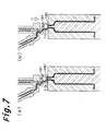
- Fig. 7 is a diagram showing steps of another production method of a barrel according to the present invention.
- the production method includes separating a product and an injection unit by pushing off of a valve pin inside a valve gate.
- Fig. 8 is a diagram showing another production method of a barrel according to the present invention.
- a barrel for a prefilled syringe of the present invention is described.
- a preferably adopted shape of the barrel 10 of a prefilled syringe of the present invention is a cylindrical shape having a male "Luer-taper" luer tip 11 at the tip, where an injection needle can be connected in a fluid-tight manner, a shoulder portion 13 formed from a proximal end 11a of the luer tip 11 to a cylindrical wall 12, and a finger-hooking flange 14 at an opened proximal end 10a.
- the luer tip 11 is sealed in a fluid-tight manner by a cap 20.
- a gasket 30 is inserted in the barrel 10 in a fluid-tight manner while being freely slidable.
- the gasket 30 can be connected with a plunger 40 at a proximal end 30a.
- the space from the gasket 30, inserted inside the barrel 10, to the luer tip 11 can contain a medication 50.
- a position for providing the luer tip 11 does not have to be at the center of the shoulder portion 13.
- a luer tip 61 may be provided in a position eccentric from the center of a shoulder portion 63.
- the barrel 10 has at least a three-layer structure of an innermost layer 15, an outermost layer 16, and an intermediate layer 17 between the innermost layer 15 and the outermost layer 16.
- the innermost layer 15 and the outermost layer 16 are preferably formed from the same material, and examples of preferable materials include polyethylene, polypropylene, a mixture of polyethylene and polypropylene, and a polyolefin resin such as cyclic polyolefin.
- any resin known for use as a medical material such as polycarbonate, a methacrylate resin, and poly (4-methyl-1-pentene), which does not interact with the medication 50 contained inside the barrel 10, and having no risk of elution or the like can be preferably adopted.
- the material for the intermediate layer 17 is selected from a resin excelling in a gas barrier property, a resin excelling in a water vapor barrier property, and a resin excelling in thermal resistance.
- resins excelling in a gas barrier property and a water vapor barrier property include an ethylene vinyl alcohol copolymer, polyacrylonitrile, vinylidene chloride, polyvinyl alcohol, nylon, polyester, or the like.
- a resin excelling in thermal resistance include polypropylene, poly-4-methylpentene-1, polyester, polycarbonate, polyether imide, polyacrylate, or the like.
- the intermediate layer 17 is not required to be a single layer and may be a multilayer structure with two or more layers.
- a barrel for a prefilled syringe which has a low risk of interacting with a medication or eluting thereinto, excels in barrier property, and is highly safe, can be provided.
- securing of the barrier property of the barrel 10 is further ensured by forming the intermediate layer 17 up to the vicinity of the luer tip surface 11b.
- the intermediate layer 17 must not be exposed at the luer tip surface 11b. The reason is that if a gap exists between the luer tip surface 11b and a cap 20, the medication 50 and the luer tip surface 11b are at a high risk of coming into contact with each other.
- the medication 50 and the luer tip surface 11b have a high chance of coming into contact with each other, so there is a risk of elution from the intermediate layer 17 into the medication 50.
- a tip 97a of an intermediate layer 97 of a cylindrical wall portion 82 of a barrel 80 can be formed up to a rim portion 83a of a shoulder portion 83.
- the shoulder portion 83 must be provided with a barrier property by molding a thick portion of the polyolefin resin.
- the cylindrical wall portion 82 of the barrel 80 for visually observing a time course of medication contained therein and insoluble contaminants, must be provided with high transparency and, thus, cannot be thickly molded. Therefore, providing a barrier property by the intermediate layer 97 is indispensable.
- the intermediate layer 17 does not have to be formed in the direction of the proximal end 10a from the proximal end 30a of an expected (initial) insertion position of the gasket 30 to be inserted inside the barrel 10.
- a medication does not exist in the space from the proximal end 30a of the gasket 30 to the proximal end 10a of the barrel 10. Therefore, there is no need to provide a barrier property.
- the gasket 30 is formed of a butyl rubber, a thermoplastic elastomer, or the like.
- the proximal end thereof is provided with a securing means such as a female screw 31 with which the plunger 40 provided with a male screw 41 at the tip thereof can be secured.
- the cap 20 is formed of a butyl rubber, a thermoplastic elastomer, or the like. As shown in Fig. 4, when the intermediate layer is not formed up to the vicinity of a luer tip surface 81b, the cap must have a thickness which ensures a sufficient gas barrier property and water vapor barrier property.
- the medication 50 may be any of a solid preparation and a liquid solution.
- a solution that causes problems of an increase in concentration and a decrease in volume by water vapor evaporation is preferable.
- a solution, the quality of which degrades from the effect of oxygen, is most preferable.
- a production method for a barrel used for a prefilled syringe according to the present invention is described.
- a polyolefin resin 120 is injected from a gate 100, provided at a position corresponding to the luer tip surface of the barrel portion of a cavity 90, into the cavity 90 using a first injection unit 110.
- a resin excelling in a barrier property 140 is injected into the cavity 90 using a second injection unit 130.
- the polyolefin resin 120 which is injected first is cooled on wall surfaces of cavity mold 150 and core mold 160 to form a skin layer.
- the resin excelling in barrier property 140 becomes a core layer having fluidity, moving through a gap of the skin layer toward an end portion 90a of the cavity 90.
- the amount of the polyolefin resin 120 injected first is preferably adjusted so that the proximal end 10a of the barrel 10 to the proximal end 30a of the gasket 30 is eventually filled, as shown in Fig. 1(a). The reason is that the intermediate layer 17 does not necessarily have to be formed in the direction of the proximal end 10a of the barrel 10 from the proximal end 30a of the gasket 30.
- the polyolefin resin 120 is injected again as shown in Fig. 5(c).
- the injection unit 170 and the luer tip surface 11b are separated as shown in Fig. 6(b), thereby producing a barrel for a prefilled syringe used in the present invention.
- the polyolefin resin injection of a specific amount in advance may be stopped after injecting the specific amount, or the injection of the resin excelling in barrier property may be started without stopping the injection as described, for example, in U.S. Patent No. 4,535,901 which is incorporated herein by reference.
- a tip 131a of the inner nozzle 131 is preferably pushed off to come closely into contact with the luer tip surface 11b. The reason is that by doing so, an unnecessary runner does not remain in the luer tip surface 11b, so that adjustment of dimensional accuracy of the luer tip surface 11b is not required after injection molding. Further, as shown in Fig. 7, a valve pin 181 provided inside a valve gate 180 may be pushed off toward the direction of the luer tip surface 11b instead of pushing off the inner nozzle 131.
- the pushing off step of the inner nozzle 131 or the valve pin 181 is preferably conducted after the luer tip surface 11b is coated with the polyolefin resin 120 as shown in Fig. 5(c). The reason is that, as described before, the intermediate layer 17 composed of a resin excelling in barrier property 140 must not be exposed at the luer tip surface 11b.
- a runner is formed at the luer tip surface 11b. The runner may be cut off after taking the barrel out from the mold.
- the polyolefin resin 120 is first injected from a gate 190, provided at a position corresponding to the center of the luer tip surface of the barrel, into a cavity 210 using a first injection unit 200.
- the resin excelling in barrier property 140 is injected into the cavity 210 using a second injection unit 220.
- the polyolefin resin 120 which is injected first is cooled at the wall surfaces of cavity mold 230 and core mold 240 to form a skin layer.
- the resin excelling in barrier property 140 becomes a core layer having fluidity and moves through the space toward the direction of an end 210a of the cavity 210 to eventually reach the state shown in Fig. 8(c).
- the resin excelling in barrier property 140 does not have to fill the portion inside the luer tip 61.
- the reason is that the luer tip 61 is sealed with the cap 20 or the like, so the cap 20 or the like provides a barrier property to the luer tip portion 61.
- the amount of the polyolefin injected first is preferably adjusted so that the proximal end 10a of the barrel to the distal end 30a which is the expected insertion position of the gasket 30 is filled as described with reference to Fig. 1.
- the injection of the resin 140 is stopped. After taking out the molded product from the mold, an unnecessary runner is removed, thereby producing the prefilled syringe barrel of the present invention.
- the injection of the polyolefin resin in a specific amount in advance may be stopped after injecting the specific amount, or the injection of the resin excelling in barrier property may be started without stopping the injection. Further, if it is not desired to leave an unnecessary runner at the gate, a method using the inner nozzle or the valve gate and the valve pin, as shown in Fig. 6 or Fig. 7, can be used.
- the gate can be provided at an arbitrary position of the barrel tip surface.
- a weld line appears on the cylindrical wall of the barrel located symmetric to the central axis of the gate and the barrel. This creates a risk that the intermediate layer is not formed because the second resin does not pervade through the weld line. Therefore, it is preferable to provide the gate at the center of the tip surface of the barrel by decentering the position of the luer tip when not providing a gate at the luer tip surface.
- the number of injection units may be increased to inject the successive resin after stopping the injection of the prior resin as the first resin, second resin, third resin, and so on.
- timing of the start of the injection inside the cavity may be sequentially adjusted.
- a gas barrier property and a water vapor barrier property can be imparted to a barrel for a prefilled syringe solely through a step of injecting a resin into a single mold.
- a gas barrier property, a water vapor barrier property, and a thermal resistance property can be easily imparted with about the same effort and time as a general production method for a syringe.
- an adhesive or a bonding layer does not have to be provided, and a portion in contact with a medication is totally coated with the polyolefin resin. Therefore, a risk of interaction of the medication with the barrel or elution of resin used for the barrel during sterilization or storage is low, and safety is extremely high.
- a container itself has a barrier property, so external packaging material becomes unnecessary, contributing to a savings in resources as well as a savings in storage space, and thereby being convenient for carrying.
Landscapes
- Engineering & Computer Science (AREA)
- Health & Medical Sciences (AREA)
- Manufacturing & Machinery (AREA)
- Mechanical Engineering (AREA)
- Hematology (AREA)
- General Health & Medical Sciences (AREA)
- Biomedical Technology (AREA)
- Heart & Thoracic Surgery (AREA)
- Vascular Medicine (AREA)
- Life Sciences & Earth Sciences (AREA)
- Animal Behavior & Ethology (AREA)
- Anesthesiology (AREA)
- Public Health (AREA)
- Veterinary Medicine (AREA)
- Infusion, Injection, And Reservoir Apparatuses (AREA)
- Injection Moulding Of Plastics Or The Like (AREA)
- Packages (AREA)
- Wrappers (AREA)
Abstract
Description
Claims (6)
- A prefilled syringe comprising: a shoulder portion (13; 83) provided with a luer tip (11; 61) arranged to be connected to an injection needle (70) at a tip thereof; a barrel (10; 80) closed by the shoulder portion (13; 83) and having an open proximal end (10a); and a gasket (30) inserted adjacent to the open proximal end (10a) of the barrel (10; 80) in a fluid-tight manner while being freely slidable, a medication (50) being contained inside the barrel (10; 80), wherein
the barrel (10; 80) has a multilayer structure in which an innermost layer (15) and an outermost layer (16) are both made of a polyolefin resin, and an intermediate layer (17; 97) is sandwiched by the innermost layer (15) and the outermost layer (16; 61) and is composed of at least one layer made of a resin excelling in a barrier property. - A prefilled syringe according to claim 1, wherein the intermediate layer (17) is formed up to a vicinity of a surface of the tip of the luer tip (11).
- A prefilled syringe according to claim 1, wherein:an end (97a) of the intermediate layer (97) in a cylindrical wall portion (82) of the barrel (80) is formed up to a rim (83a) of the shoulder portion (83);the shoulder portion (83) formed with the polyolefin resin has a thickness sufficient to exert a barrier property; andthe luer tip (11; 61) is sealed by a cap (20) having a barrier property.
- A prefilled syringe according to any one of claims 1-3, wherein the intermediate layer (17; 97) is not formed in a direction of the proximal end (10a) of the barrel (10; 80) from a proximal end (30a) of an initial insertion position of the gasket (30) inserted in the barrel (10; 80).
- A production method for a barrel (10; 80) of a prefilled syringe according to any one of claims 1-4 comprising the sequential steps of:(a) injecting a specific amount of a polyolefin resin (120) from an injection unit (110, 130, 170) into a cavity (90) from a gate (100) provided at a position corresponding to a luer tip surface (11b; 81b) of the barrel (10; 80);(b) injecting a specific amount of a resin (140) excelling in barrier property;(c) injecting a specific amount of the polyolefin resin (120) again; and(d) separating the luer tip surface (11b; 81b) and the injection unit by pushing off at least one of a valve pin (181) provided inside a valve gate (180) and an inner nozzle (131) of the injection unit (110, 130, 170) toward a direction of the luer tip surface (11b; 81b).
- A production method for a barrel (10; 80) of a prefilled syringe according to any one of claims 1-4 comprising the steps of:(a) injecting a specific amount of a polyolefin resin (120) into a cavity (210) from a gate (190) provided at an arbitrary position (13; 83) of the shoulder portion (13; 83) of the barrel (10; 80); and(b) thereafter injecting a specific amount of a resin (140) excelling in barrier property.
Applications Claiming Priority (2)
| Application Number | Priority Date | Filing Date | Title |
|---|---|---|---|
| JP2003019401 | 2003-01-28 | ||
| JP2003019401A JP2004229750A (en) | 2003-01-28 | 2003-01-28 | Method for manufacturing prefilled syringe and barrel thereof |
Publications (3)
| Publication Number | Publication Date |
|---|---|
| EP1442762A2 true EP1442762A2 (en) | 2004-08-04 |
| EP1442762A3 EP1442762A3 (en) | 2005-09-28 |
| EP1442762B1 EP1442762B1 (en) | 2007-04-18 |
Family
ID=32652854
Family Applications (1)
| Application Number | Title | Priority Date | Filing Date |
|---|---|---|---|
| EP04001191A Expired - Lifetime EP1442762B1 (en) | 2003-01-28 | 2004-01-21 | Prefilled syringe and production method for a barrel thereof |
Country Status (5)
| Country | Link |
|---|---|
| US (1) | US7998120B2 (en) |
| EP (1) | EP1442762B1 (en) |
| JP (1) | JP2004229750A (en) |
| AT (1) | ATE359841T1 (en) |
| DE (1) | DE602004005902T2 (en) |
Cited By (6)
| Publication number | Priority date | Publication date | Assignee | Title |
|---|---|---|---|---|
| WO2011035449A3 (en) * | 2009-09-22 | 2011-05-26 | Medmix System Ag | Sealed container comprising a displaceable piston |
| EP2946802A1 (en) * | 2011-10-07 | 2015-11-25 | Mitsubishi Gas Chemical Company, Inc. | Medical packaging container |
| US9301587B2 (en) | 2013-01-14 | 2016-04-05 | Stephen D'Amico | Hair color (or dye) storage, dispensing and measurement (or measuring) system |
| CN106584771A (en) * | 2016-10-19 | 2017-04-26 | 广州华研精密机械有限公司 | Injection molding process of syringe |
| CN108289786A (en) * | 2015-10-09 | 2018-07-17 | 三菱瓦斯化学株式会社 | The manufacturing method of medical laminated vessel and medical laminated vessel |
| EP3659594B1 (en) | 2018-11-30 | 2020-11-18 | Klaus Stegemann | A sterile solution with an application injector comprising a medical agent and method for producing same |
Families Citing this family (70)
| Publication number | Priority date | Publication date | Assignee | Title |
|---|---|---|---|---|
| US7824697B2 (en) | 2004-07-12 | 2010-11-02 | Board Of Regents, The University Of Texas System | High concentration baclofen preparations |
| CN101247843B (en) * | 2005-08-22 | 2010-09-29 | 尼普洛株式会社 | prefilled syringe |
| US20150258279A1 (en) | 2008-03-18 | 2015-09-17 | Mallinckrodt Llc | Intrathecal baclofen pharmaceutical dosage forms and related delivery system |
| US8969414B2 (en) | 2009-02-06 | 2015-03-03 | Mallinckrodt Llc | Intrathecal baclofen pharmaceutical dosage forms with fewer degradation products |
| JP5933975B2 (en) | 2008-11-12 | 2016-06-15 | メディミューン,エルエルシー | Antibody preparation |
| EP2251455B1 (en) | 2009-05-13 | 2017-09-06 | SiO2 Medical Products, Inc. | PECVD coating using an organosilicon precursor |
| US7985188B2 (en) | 2009-05-13 | 2011-07-26 | Cv Holdings Llc | Vessel, coating, inspection and processing apparatus |
| GB2471304B (en) | 2009-06-24 | 2013-12-11 | Oval Medical Technologies Ltd | A pre-filled syringe or autoinjector |
| US9458536B2 (en) | 2009-07-02 | 2016-10-04 | Sio2 Medical Products, Inc. | PECVD coating methods for capped syringes, cartridges and other articles |
| WO2011107954A2 (en) * | 2010-03-03 | 2011-09-09 | Atul Sardana | Single use safety syringe with spring actuated needle stick injury prevention and auto disable mechanism |
| US11624115B2 (en) | 2010-05-12 | 2023-04-11 | Sio2 Medical Products, Inc. | Syringe with PECVD lubrication |
| WO2011143509A1 (en) | 2010-05-12 | 2011-11-17 | Cv Holdings, Llc | Vessel outgassing inspection methods |
| WO2012022734A2 (en) | 2010-08-16 | 2012-02-23 | Medimmune Limited | Anti-icam-1 antibodies and methods of use |
| US9878101B2 (en) | 2010-11-12 | 2018-01-30 | Sio2 Medical Products, Inc. | Cyclic olefin polymer vessels and vessel coating methods |
| US9272095B2 (en) | 2011-04-01 | 2016-03-01 | Sio2 Medical Products, Inc. | Vessels, contact surfaces, and coating and inspection apparatus and methods |
| WO2013009897A1 (en) | 2011-07-11 | 2013-01-17 | Medpro Safety Products, Inc. | Fluid delivery device and methods |
| CN103930595A (en) | 2011-11-11 | 2014-07-16 | Sio2医药产品公司 | Passivation, ph protective or lubricity coating for pharmaceutical package, coating process and apparatus |
| US11116695B2 (en) | 2011-11-11 | 2021-09-14 | Sio2 Medical Products, Inc. | Blood sample collection tube |
| DE102012008297A1 (en) * | 2011-11-16 | 2013-05-16 | Lts Lohmann Therapie-Systeme Ag | Cylinder-piston-unit has cylinder receiving injection solution and piston, where cylinder has cylinder inner wall, outer wall and storage cavity between cylinder inner wall and outer wall |
| CN103958604B (en) | 2011-11-25 | 2016-05-04 | 三菱瓦斯化学株式会社 | Oxygen-absorbing resin composition, oxygen-absorbing molded article using the same, multilayer body, container, injection molded article, and medical container using the same |
| EP2792713B1 (en) | 2011-12-16 | 2020-01-15 | Mitsubishi Gas Chemical Company, Inc. | Oxygen-absorbing resin molded article obtained from an oxygen-absorbing resin composition, and multilayer body, container, injection-molded article and medical container using the composition |
| US9732167B2 (en) | 2012-02-08 | 2017-08-15 | Mitsubishi Gas Chemical Company, Inc. | Oxygen-absorbing resin composition and oxygen-absorbing multilayer body using same, and molded article and medical container using these |
| WO2013158273A1 (en) | 2012-04-20 | 2013-10-24 | Abbvie Inc. | Methods to modulate c-terminal lysine variant distribution |
| US9265889B2 (en) | 2012-04-25 | 2016-02-23 | Adar Medtech, Inc. | Prefilled medical injection device |
| US10780228B2 (en) | 2012-05-07 | 2020-09-22 | Medline Industries, Inc. | Prefilled container systems |
| EP2846856A1 (en) | 2012-05-09 | 2015-03-18 | SiO2 Medical Products, Inc. | Inspection methods for pecvd coatings |
| CA2887352A1 (en) | 2012-05-09 | 2013-11-14 | Sio2 Medical Products, Inc. | Saccharide protective coating for pharmaceutical package |
| US9249182B2 (en) | 2012-05-24 | 2016-02-02 | Abbvie, Inc. | Purification of antibodies using hydrophobic interaction chromatography |
| US8870028B2 (en) | 2012-05-25 | 2014-10-28 | Restek Corporation | Dispensing device |
| CN106170582A (en) | 2012-07-03 | 2016-11-30 | Sio2医药产品公司 | SiOx barriers and coating methods for pharmaceutical packaging |
| US20150297800A1 (en) | 2012-07-03 | 2015-10-22 | Sio2 Medical Products, Inc. | SiOx BARRIER FOR PHARMACEUTICAL PACKAGE AND COATING PROCESS |
| FR2994851B1 (en) * | 2012-09-04 | 2015-08-21 | Rexam Healthcare La Verpillier | APPARATUS FOR INJECTING PHARMACEUTICAL LIQUID CONFIGURED TO BE PRE-FILLED |
| JP2014068767A (en) * | 2012-09-28 | 2014-04-21 | Mitsubishi Gas Chemical Co Inc | Medical multilayer container |
| JP6509734B2 (en) | 2012-11-01 | 2019-05-08 | エスアイオーツー・メディカル・プロダクツ・インコーポレイテッド | Film inspection method |
| US9903782B2 (en) | 2012-11-16 | 2018-02-27 | Sio2 Medical Products, Inc. | Method and apparatus for detecting rapid barrier coating integrity characteristics |
| WO2014085348A2 (en) | 2012-11-30 | 2014-06-05 | Sio2 Medical Products, Inc. | Controlling the uniformity of pecvd deposition on medical syringes, cartridges, and the like |
| US9764093B2 (en) | 2012-11-30 | 2017-09-19 | Sio2 Medical Products, Inc. | Controlling the uniformity of PECVD deposition |
| ES2882063T3 (en) | 2012-12-03 | 2021-12-01 | Novobiotic Pharmaceuticals Llc | New depsipeptide and its uses |
| WO2014112113A1 (en) * | 2013-01-21 | 2014-07-24 | テルモ株式会社 | Container for housing syringe barrels |
| EP2961858B1 (en) | 2013-03-01 | 2022-09-07 | Si02 Medical Products, Inc. | Coated syringe. |
| KR20150126393A (en) | 2013-03-06 | 2015-11-11 | 미츠비시 가스 가가쿠 가부시키가이샤 | Oxygen-absorbing multilayer body, oxygen-absorbing container, oxygen-absorbing airtight container, oxygen-absorbing push-through pack, and storage method using same |
| WO2014136918A1 (en) | 2013-03-06 | 2014-09-12 | 三菱瓦斯化学株式会社 | Oxygen-absorbing medical multiwall container and biopharmaceutical storage method |
| US9937099B2 (en) | 2013-03-11 | 2018-04-10 | Sio2 Medical Products, Inc. | Trilayer coated pharmaceutical packaging with low oxygen transmission rate |
| CN105392916B (en) | 2013-03-11 | 2019-03-08 | Sio2医药产品公司 | Coated Packaging Materials |
| WO2014140095A1 (en) | 2013-03-14 | 2014-09-18 | Becton Dickinson France S.A.S. | Injectable morphine formulations |
| KR20150129033A (en) | 2013-03-14 | 2015-11-18 | 애브비 인코포레이티드 | Low acidic species compositions and methods for producing and using the same |
| CA2899449A1 (en) | 2013-03-14 | 2014-10-02 | Abbvie Inc. | Low acidic species compositions and methods for producing the same using displacement chromatography |
| ES2695158T3 (en) | 2013-03-14 | 2019-01-02 | Fresenius Kabi Deutschland Gmbh | Packaging system for oxygen-sensitive drugs |
| EP2971227B1 (en) | 2013-03-15 | 2017-11-15 | Si02 Medical Products, Inc. | Coating method. |
| EP4137139A1 (en) | 2013-07-10 | 2023-02-22 | Matrix Biology Institute | Compositions of hyaluronan with high elasticity and uses thereof |
| WO2015050959A1 (en) | 2013-10-01 | 2015-04-09 | Yale University | Anti-kit antibodies and methods of use thereof |
| JP2015073635A (en) * | 2013-10-07 | 2015-04-20 | 三菱瓦斯化学株式会社 | Multilayer syringe barrel and prefilled syringe |
| CA2927835A1 (en) | 2013-12-06 | 2015-06-11 | Genentech, Inc. | Apparatus and methods for low-volume medicament delivery |
| KR102348201B1 (en) * | 2014-02-10 | 2022-01-10 | 미츠비시 가스 가가쿠 가부시키가이샤 | Syringe barrel production method |
| US11066745B2 (en) | 2014-03-28 | 2021-07-20 | Sio2 Medical Products, Inc. | Antistatic coatings for plastic vessels |
| WO2015147305A1 (en) * | 2014-03-28 | 2015-10-01 | テルモ株式会社 | Packaged drug-filled container |
| US20170226552A1 (en) | 2014-07-03 | 2017-08-10 | Abbvie Inc. | Methods for modulating protein glycosylation profiles of recombinant protein therapeutics using cobalt |
| WO2016007764A1 (en) | 2014-07-09 | 2016-01-14 | Abbvie Inc. | Methods for modulating the glycosylation profile of recombinant proteins using non-commonly used sugars |
| KR102455905B1 (en) * | 2014-10-30 | 2022-10-17 | 추가이 세이야쿠 가부시키가이샤 | Pre-filled syringe preparation with needle, which is equipped with syringe cap |
| BR112017008658A2 (en) | 2014-10-30 | 2017-12-19 | Hoffmann La Roche | syringe and method of preparation |
| WO2016144773A1 (en) | 2015-03-06 | 2016-09-15 | Abbvie Inc. | Arabinosylated glycoproteins |
| US11077233B2 (en) | 2015-08-18 | 2021-08-03 | Sio2 Medical Products, Inc. | Pharmaceutical and other packaging with low oxygen transmission rate |
| ES2871199T3 (en) | 2015-09-24 | 2021-10-28 | Matrix Biology Inst | High Elastic Hyaluronan Compositions and Methods of Using Them |
| EP3862384A3 (en) | 2015-11-16 | 2022-04-13 | Si02 Medical Products, Inc. | Polymeric substrate with a surface having reduced biomolecule adhesion, and thermoplastic articles of such substrate |
| EP3418208B1 (en) | 2016-02-16 | 2021-11-03 | Mitsubishi Gas Chemical Company, Inc. | Laminate container and application for same |
| WO2017147003A1 (en) | 2016-02-26 | 2017-08-31 | Novobiotic Pharmaceuticals, Llc | Novel macrocyclic antibiotics and uses thereof |
| WO2017188267A1 (en) | 2016-04-25 | 2017-11-02 | テルモ株式会社 | Syringe barrel for pre-filled syringe, syringe system, and pre-filled syringe |
| US11628257B2 (en) * | 2016-07-11 | 2023-04-18 | Becton Dickinson France | Method for reducing an amount of subvisible particles in a pharmaceutical composition |
| US11203616B2 (en) | 2017-04-04 | 2021-12-21 | Novobiotic Pharmaceuticals, Llc | Depsipeptides and uses thereof |
| CN112549420B (en) * | 2020-11-05 | 2022-10-25 | 山东永聚医药科技有限公司 | Preparation process of polymer prefilled syringe |
Family Cites Families (15)
| Publication number | Priority date | Publication date | Assignee | Title |
|---|---|---|---|---|
| US3375825A (en) * | 1965-09-02 | 1968-04-02 | Becton Dickinson Co | Prefilled syringe |
| AU549286B2 (en) | 1981-01-22 | 1986-01-23 | Toyo Boseki K.K. | Blow moulded multiply vessel |
| US5554125A (en) * | 1987-07-08 | 1996-09-10 | Reynolds; David L. | Prefilled vial syringe |
| US5131830A (en) * | 1987-10-30 | 1992-07-21 | Nissei Asb Machine Co., Ltd. | Multi-layer molding nozzle |
| US5125898A (en) * | 1990-03-22 | 1992-06-30 | Harry Kaufhold, Jr. | Disposable syringe with automatic needle retraction |
| DE4438360C2 (en) * | 1994-10-27 | 1999-05-20 | Schott Glas | Pre-fillable, low-particle, sterile disposable syringe for the injection of preparations and methods for their manufacture |
| JP3623294B2 (en) * | 1995-11-28 | 2005-02-23 | 株式会社新素材総合研究所 | Medical container containing electrolyte and method for producing the same |
| JPH09173450A (en) * | 1995-12-26 | 1997-07-08 | Nissho Corp | Prefilled syringe |
| JPH1057446A (en) | 1996-08-23 | 1998-03-03 | Material Eng Tech Lab Inc | Chemical container having gas barrier property and its production |
| US6053895A (en) * | 1996-11-05 | 2000-04-25 | Schering Aktiengesellschaft | Syringe with a new and improved plug |
| JPH11332984A (en) | 1998-05-26 | 1999-12-07 | Terumo Corp | Medicinal liquid-containing syringe |
| JP2001112867A (en) * | 1999-10-18 | 2001-04-24 | Terumo Corp | Syringe containing drug |
| US20030032928A1 (en) * | 2000-03-02 | 2003-02-13 | Morihiro Sudo | Prefilled syringe assembly |
| CN101816561A (en) * | 2001-06-18 | 2010-09-01 | 贝克顿迪肯森公司 | Laminated vessel and about forming the course of processing of laminated vessel |
| JP2003199827A (en) * | 2001-12-28 | 2003-07-15 | Terumo Corp | Syringe |
-
2003
- 2003-01-28 JP JP2003019401A patent/JP2004229750A/en active Pending
-
2004
- 2004-01-21 DE DE602004005902T patent/DE602004005902T2/en not_active Expired - Lifetime
- 2004-01-21 AT AT04001191T patent/ATE359841T1/en not_active IP Right Cessation
- 2004-01-21 EP EP04001191A patent/EP1442762B1/en not_active Expired - Lifetime
- 2004-01-23 US US10/762,530 patent/US7998120B2/en not_active Expired - Fee Related
Cited By (6)
| Publication number | Priority date | Publication date | Assignee | Title |
|---|---|---|---|---|
| WO2011035449A3 (en) * | 2009-09-22 | 2011-05-26 | Medmix System Ag | Sealed container comprising a displaceable piston |
| EP2946802A1 (en) * | 2011-10-07 | 2015-11-25 | Mitsubishi Gas Chemical Company, Inc. | Medical packaging container |
| US9301587B2 (en) | 2013-01-14 | 2016-04-05 | Stephen D'Amico | Hair color (or dye) storage, dispensing and measurement (or measuring) system |
| CN108289786A (en) * | 2015-10-09 | 2018-07-17 | 三菱瓦斯化学株式会社 | The manufacturing method of medical laminated vessel and medical laminated vessel |
| CN106584771A (en) * | 2016-10-19 | 2017-04-26 | 广州华研精密机械有限公司 | Injection molding process of syringe |
| EP3659594B1 (en) | 2018-11-30 | 2020-11-18 | Klaus Stegemann | A sterile solution with an application injector comprising a medical agent and method for producing same |
Also Published As
| Publication number | Publication date |
|---|---|
| JP2004229750A (en) | 2004-08-19 |
| US20040267194A1 (en) | 2004-12-30 |
| DE602004005902T2 (en) | 2008-01-17 |
| DE602004005902D1 (en) | 2007-05-31 |
| EP1442762A3 (en) | 2005-09-28 |
| EP1442762B1 (en) | 2007-04-18 |
| US7998120B2 (en) | 2011-08-16 |
| ATE359841T1 (en) | 2007-05-15 |
Similar Documents
| Publication | Publication Date | Title |
|---|---|---|
| US7998120B2 (en) | Prefilled syringe and production method for a barrel thereof | |
| US7799400B2 (en) | Multi-layered plastic body for medical applications | |
| CN1516642B (en) | Multilayer container and process for forming multilayer container | |
| US6607685B2 (en) | Method of producing pierceable stopper | |
| KR101737357B1 (en) | Integral two layer preform, process and apparatus for the production thereof, process for producing a blow-moulded bag-in-container, and bag-in-container thus produced | |
| EP0092979B1 (en) | Bottle-shaped container | |
| US20150224263A1 (en) | Device For Injecting A Pharmaceutical Liquid, Configured To Be Pre-filled | |
| JP2016532469A (en) | Switchable plunger, film-coated plunger and associated syringe assembly | |
| US20060163515A1 (en) | Fluid handling device and method of making same | |
| AU2002315163A1 (en) | Multilayer containers and process for forming multilayer containers | |
| CA2960135A1 (en) | Three-position plungers, film coated plungers and related syringe assemblies | |
| US11850778B2 (en) | Method for producing a syringe with an integrated closure element | |
| EP1899128B1 (en) | Device and process for manufacturing a preform, preform for blow moulding a container and such a container | |
| EP3057632B1 (en) | Methods and apparatuses for injection molding walled structures | |
| KR20060029454A (en) | Two-way sealing integral tip for tubeless infusion pack and its manufacturing method | |
| KR102444788B1 (en) | Manufacturing mold assembly for hydrogen storage tank and the manufacturing method for same using this | |
| EP4464289B1 (en) | Drop-type drug tube and its manufacturing method | |
| CN1018899B (en) | Injection molding apparatus for multi-layer bottom-sealed parison | |
| WO2025248432A1 (en) | Medical product comprising an ampoule made from a plastic material comprising a neuraxial drug | |
| CN211485692U (en) | A infusion mouth that can break for sealing infusion bag liquid outlet and manufacture equipment thereof | |
| JPS6149980B2 (en) | ||
| CN1442346A (en) | Pesticide packaging bottle and its panufacturing method and special manufacturing equipment | |
| CN114787043A (en) | Discharge member, storage container, method for manufacturing discharge member, mold for injection molding, and discharge member with closing member | |
| HK1017624A (en) | Needless injector drug capsule and filling method | |
| NZ759333B2 (en) | Three-position plungers, film coated plungers and related syringe assemblies |
Legal Events
| Date | Code | Title | Description |
|---|---|---|---|
| PUAI | Public reference made under article 153(3) epc to a published international application that has entered the european phase |
Free format text: ORIGINAL CODE: 0009012 |
|
| AK | Designated contracting states |
Kind code of ref document: A2 Designated state(s): AT BE BG CH CY CZ DE DK EE ES FI FR GB GR HU IE IT LI LU MC NL PT RO SE SI SK TR |
|
| AX | Request for extension of the european patent |
Extension state: AL LT LV MK |
|
| PUAL | Search report despatched |
Free format text: ORIGINAL CODE: 0009013 |
|
| AK | Designated contracting states |
Kind code of ref document: A3 Designated state(s): AT BE BG CH CY CZ DE DK EE ES FI FR GB GR HU IE IT LI LU MC NL PT RO SE SI SK TR |
|
| AX | Request for extension of the european patent |
Extension state: AL LT LV MK |
|
| RIC1 | Information provided on ipc code assigned before grant |
Ipc: 7A 61M 5/28 A Ipc: 7A 61M 5/31 B Ipc: 7B 29C 45/16 B Ipc: 7B 32B 27/32 B |
|
| 17P | Request for examination filed |
Effective date: 20051013 |
|
| AKX | Designation fees paid |
Designated state(s): AT BE BG CH CY CZ DE DK EE ES FI FR GB GR HU IE IT LI LU MC NL PT RO SE SI SK TR |
|
| GRAP | Despatch of communication of intention to grant a patent |
Free format text: ORIGINAL CODE: EPIDOSNIGR1 |
|
| GRAS | Grant fee paid |
Free format text: ORIGINAL CODE: EPIDOSNIGR3 |
|
| GRAA | (expected) grant |
Free format text: ORIGINAL CODE: 0009210 |
|
| AK | Designated contracting states |
Kind code of ref document: B1 Designated state(s): AT BE BG CH CY CZ DE DK EE ES FI FR GB GR HU IE IT LI LU MC NL PT RO SE SI SK TR |
|
| PG25 | Lapsed in a contracting state [announced via postgrant information from national office to epo] |
Ref country code: SI Free format text: LAPSE BECAUSE OF FAILURE TO SUBMIT A TRANSLATION OF THE DESCRIPTION OR TO PAY THE FEE WITHIN THE PRESCRIBED TIME-LIMIT Effective date: 20070418 Ref country code: LI Free format text: LAPSE BECAUSE OF FAILURE TO SUBMIT A TRANSLATION OF THE DESCRIPTION OR TO PAY THE FEE WITHIN THE PRESCRIBED TIME-LIMIT Effective date: 20070418 Ref country code: CH Free format text: LAPSE BECAUSE OF FAILURE TO SUBMIT A TRANSLATION OF THE DESCRIPTION OR TO PAY THE FEE WITHIN THE PRESCRIBED TIME-LIMIT Effective date: 20070418 Ref country code: FI Free format text: LAPSE BECAUSE OF FAILURE TO SUBMIT A TRANSLATION OF THE DESCRIPTION OR TO PAY THE FEE WITHIN THE PRESCRIBED TIME-LIMIT Effective date: 20070418 |
|
| REG | Reference to a national code |
Ref country code: CH Ref legal event code: EP |
|
| REG | Reference to a national code |
Ref country code: IE Ref legal event code: FG4D |
|
| REF | Corresponds to: |
Ref document number: 602004005902 Country of ref document: DE Date of ref document: 20070531 Kind code of ref document: P |
|
| PG25 | Lapsed in a contracting state [announced via postgrant information from national office to epo] |
Ref country code: SE Free format text: LAPSE BECAUSE OF FAILURE TO SUBMIT A TRANSLATION OF THE DESCRIPTION OR TO PAY THE FEE WITHIN THE PRESCRIBED TIME-LIMIT Effective date: 20070718 |
|
| PG25 | Lapsed in a contracting state [announced via postgrant information from national office to epo] |
Ref country code: ES Free format text: LAPSE BECAUSE OF FAILURE TO SUBMIT A TRANSLATION OF THE DESCRIPTION OR TO PAY THE FEE WITHIN THE PRESCRIBED TIME-LIMIT Effective date: 20070729 |
|
| ET | Fr: translation filed | ||
| PG25 | Lapsed in a contracting state [announced via postgrant information from national office to epo] |
Ref country code: PT Free format text: LAPSE BECAUSE OF FAILURE TO SUBMIT A TRANSLATION OF THE DESCRIPTION OR TO PAY THE FEE WITHIN THE PRESCRIBED TIME-LIMIT Effective date: 20070918 |
|
| REG | Reference to a national code |
Ref country code: CH Ref legal event code: PL |
|
| NLV1 | Nl: lapsed or annulled due to failure to fulfill the requirements of art. 29p and 29m of the patents act | ||
| PG25 | Lapsed in a contracting state [announced via postgrant information from national office to epo] |
Ref country code: AT Free format text: LAPSE BECAUSE OF FAILURE TO SUBMIT A TRANSLATION OF THE DESCRIPTION OR TO PAY THE FEE WITHIN THE PRESCRIBED TIME-LIMIT Effective date: 20070418 |
|
| PG25 | Lapsed in a contracting state [announced via postgrant information from national office to epo] |
Ref country code: BE Free format text: LAPSE BECAUSE OF FAILURE TO SUBMIT A TRANSLATION OF THE DESCRIPTION OR TO PAY THE FEE WITHIN THE PRESCRIBED TIME-LIMIT Effective date: 20070418 |
|
| PG25 | Lapsed in a contracting state [announced via postgrant information from national office to epo] |
Ref country code: BG Free format text: LAPSE BECAUSE OF FAILURE TO SUBMIT A TRANSLATION OF THE DESCRIPTION OR TO PAY THE FEE WITHIN THE PRESCRIBED TIME-LIMIT Effective date: 20070718 Ref country code: DK Free format text: LAPSE BECAUSE OF FAILURE TO SUBMIT A TRANSLATION OF THE DESCRIPTION OR TO PAY THE FEE WITHIN THE PRESCRIBED TIME-LIMIT Effective date: 20070418 Ref country code: NL Free format text: LAPSE BECAUSE OF FAILURE TO SUBMIT A TRANSLATION OF THE DESCRIPTION OR TO PAY THE FEE WITHIN THE PRESCRIBED TIME-LIMIT Effective date: 20070418 Ref country code: CZ Free format text: LAPSE BECAUSE OF FAILURE TO SUBMIT A TRANSLATION OF THE DESCRIPTION OR TO PAY THE FEE WITHIN THE PRESCRIBED TIME-LIMIT Effective date: 20070418 |
|
| PLBE | No opposition filed within time limit |
Free format text: ORIGINAL CODE: 0009261 |
|
| STAA | Information on the status of an ep patent application or granted ep patent |
Free format text: STATUS: NO OPPOSITION FILED WITHIN TIME LIMIT |
|
| PG25 | Lapsed in a contracting state [announced via postgrant information from national office to epo] |
Ref country code: SK Free format text: LAPSE BECAUSE OF FAILURE TO SUBMIT A TRANSLATION OF THE DESCRIPTION OR TO PAY THE FEE WITHIN THE PRESCRIBED TIME-LIMIT Effective date: 20070418 |
|
| 26N | No opposition filed |
Effective date: 20080121 |
|
| PG25 | Lapsed in a contracting state [announced via postgrant information from national office to epo] |
Ref country code: GR Free format text: LAPSE BECAUSE OF FAILURE TO SUBMIT A TRANSLATION OF THE DESCRIPTION OR TO PAY THE FEE WITHIN THE PRESCRIBED TIME-LIMIT Effective date: 20070719 |
|
| PG25 | Lapsed in a contracting state [announced via postgrant information from national office to epo] |
Ref country code: RO Free format text: LAPSE BECAUSE OF FAILURE TO SUBMIT A TRANSLATION OF THE DESCRIPTION OR TO PAY THE FEE WITHIN THE PRESCRIBED TIME-LIMIT Effective date: 20070418 |
|
| PG25 | Lapsed in a contracting state [announced via postgrant information from national office to epo] |
Ref country code: MC Free format text: LAPSE BECAUSE OF NON-PAYMENT OF DUE FEES Effective date: 20080131 |
|
| PG25 | Lapsed in a contracting state [announced via postgrant information from national office to epo] |
Ref country code: IE Free format text: LAPSE BECAUSE OF NON-PAYMENT OF DUE FEES Effective date: 20080121 Ref country code: EE Free format text: LAPSE BECAUSE OF FAILURE TO SUBMIT A TRANSLATION OF THE DESCRIPTION OR TO PAY THE FEE WITHIN THE PRESCRIBED TIME-LIMIT Effective date: 20070418 |
|
| PG25 | Lapsed in a contracting state [announced via postgrant information from national office to epo] |
Ref country code: CY Free format text: LAPSE BECAUSE OF FAILURE TO SUBMIT A TRANSLATION OF THE DESCRIPTION OR TO PAY THE FEE WITHIN THE PRESCRIBED TIME-LIMIT Effective date: 20070418 |
|
| PG25 | Lapsed in a contracting state [announced via postgrant information from national office to epo] |
Ref country code: HU Free format text: LAPSE BECAUSE OF FAILURE TO SUBMIT A TRANSLATION OF THE DESCRIPTION OR TO PAY THE FEE WITHIN THE PRESCRIBED TIME-LIMIT Effective date: 20071019 Ref country code: LU Free format text: LAPSE BECAUSE OF NON-PAYMENT OF DUE FEES Effective date: 20080121 |
|
| PG25 | Lapsed in a contracting state [announced via postgrant information from national office to epo] |
Ref country code: TR Free format text: LAPSE BECAUSE OF FAILURE TO SUBMIT A TRANSLATION OF THE DESCRIPTION OR TO PAY THE FEE WITHIN THE PRESCRIBED TIME-LIMIT Effective date: 20070418 |
|
| REG | Reference to a national code |
Ref country code: FR Ref legal event code: PLFP Year of fee payment: 13 |
|
| REG | Reference to a national code |
Ref country code: FR Ref legal event code: PLFP Year of fee payment: 14 |
|
| REG | Reference to a national code |
Ref country code: FR Ref legal event code: PLFP Year of fee payment: 15 |
|
| PGFP | Annual fee paid to national office [announced via postgrant information from national office to epo] |
Ref country code: GB Payment date: 20220119 Year of fee payment: 19 Ref country code: DE Payment date: 20220119 Year of fee payment: 19 |
|
| PGFP | Annual fee paid to national office [announced via postgrant information from national office to epo] |
Ref country code: IT Payment date: 20220120 Year of fee payment: 19 Ref country code: FR Payment date: 20220119 Year of fee payment: 19 |
|
| REG | Reference to a national code |
Ref country code: DE Ref legal event code: R119 Ref document number: 602004005902 Country of ref document: DE |
|
| GBPC | Gb: european patent ceased through non-payment of renewal fee |
Effective date: 20230121 |
|
| PG25 | Lapsed in a contracting state [announced via postgrant information from national office to epo] |
Ref country code: GB Free format text: LAPSE BECAUSE OF NON-PAYMENT OF DUE FEES Effective date: 20230121 Ref country code: DE Free format text: LAPSE BECAUSE OF NON-PAYMENT OF DUE FEES Effective date: 20230801 |
|
| PG25 | Lapsed in a contracting state [announced via postgrant information from national office to epo] |
Ref country code: FR Free format text: LAPSE BECAUSE OF NON-PAYMENT OF DUE FEES Effective date: 20230131 |
|
| PG25 | Lapsed in a contracting state [announced via postgrant information from national office to epo] |
Ref country code: IT Free format text: LAPSE BECAUSE OF NON-PAYMENT OF DUE FEES Effective date: 20230121 |