EP1442311B1 - Rounded-conductor nmr rf resonator - Google Patents
Rounded-conductor nmr rf resonator Download PDFInfo
- Publication number
- EP1442311B1 EP1442311B1 EP02773718A EP02773718A EP1442311B1 EP 1442311 B1 EP1442311 B1 EP 1442311B1 EP 02773718 A EP02773718 A EP 02773718A EP 02773718 A EP02773718 A EP 02773718A EP 1442311 B1 EP1442311 B1 EP 1442311B1
- Authority
- EP
- European Patent Office
- Prior art keywords
- coil
- longitudinal
- ring
- conductors
- conductor
- Prior art date
- Legal status (The legal status is an assumption and is not a legal conclusion. Google has not performed a legal analysis and makes no representation as to the accuracy of the status listed.)
- Expired - Lifetime
Links
- 239000004020 conductor Substances 0.000 title claims description 71
- 230000005291 magnetic effect Effects 0.000 claims description 49
- 239000000523 sample Substances 0.000 claims description 47
- 238000005481 NMR spectroscopy Methods 0.000 claims description 39
- 230000003068 static effect Effects 0.000 claims description 6
- 238000005259 measurement Methods 0.000 description 23
- 230000035945 sensitivity Effects 0.000 description 13
- 230000001965 increasing effect Effects 0.000 description 11
- 239000000463 material Substances 0.000 description 7
- 230000004044 response Effects 0.000 description 4
- RYGMFSIKBFXOCR-UHFFFAOYSA-N Copper Chemical compound [Cu] RYGMFSIKBFXOCR-UHFFFAOYSA-N 0.000 description 3
- 229910052802 copper Inorganic materials 0.000 description 3
- 239000010949 copper Substances 0.000 description 3
- 238000004519 manufacturing process Methods 0.000 description 3
- 239000010453 quartz Substances 0.000 description 3
- VYPSYNLAJGMNEJ-UHFFFAOYSA-N silicon dioxide Inorganic materials O=[Si]=O VYPSYNLAJGMNEJ-UHFFFAOYSA-N 0.000 description 3
- 238000001644 13C nuclear magnetic resonance spectroscopy Methods 0.000 description 2
- 238000005160 1H NMR spectroscopy Methods 0.000 description 2
- 230000003247 decreasing effect Effects 0.000 description 2
- 238000010586 diagram Methods 0.000 description 2
- 238000009826 distribution Methods 0.000 description 2
- 239000011521 glass Substances 0.000 description 2
- 238000000034 method Methods 0.000 description 2
- 230000003071 parasitic effect Effects 0.000 description 2
- BASFCYQUMIYNBI-UHFFFAOYSA-N platinum Chemical compound [Pt] BASFCYQUMIYNBI-UHFFFAOYSA-N 0.000 description 2
- 229910052594 sapphire Inorganic materials 0.000 description 2
- 239000010980 sapphire Substances 0.000 description 2
- 229910018182 Al—Cu Inorganic materials 0.000 description 1
- 239000000853 adhesive Substances 0.000 description 1
- 230000001070 adhesive effect Effects 0.000 description 1
- 230000002411 adverse Effects 0.000 description 1
- XAGFODPZIPBFFR-UHFFFAOYSA-N aluminium Chemical compound [Al] XAGFODPZIPBFFR-UHFFFAOYSA-N 0.000 description 1
- 229910052782 aluminium Inorganic materials 0.000 description 1
- 239000012141 concentrate Substances 0.000 description 1
- 230000008878 coupling Effects 0.000 description 1
- 238000010168 coupling process Methods 0.000 description 1
- 238000005859 coupling reaction Methods 0.000 description 1
- 230000001419 dependent effect Effects 0.000 description 1
- 230000005292 diamagnetic effect Effects 0.000 description 1
- 239000003989 dielectric material Substances 0.000 description 1
- 230000000694 effects Effects 0.000 description 1
- 230000005684 electric field Effects 0.000 description 1
- 230000005284 excitation Effects 0.000 description 1
- 230000006872 improvement Effects 0.000 description 1
- 230000001939 inductive effect Effects 0.000 description 1
- 238000002595 magnetic resonance imaging Methods 0.000 description 1
- 230000005298 paramagnetic effect Effects 0.000 description 1
- 230000035515 penetration Effects 0.000 description 1
- 229910052697 platinum Inorganic materials 0.000 description 1
- 230000008569 process Effects 0.000 description 1
- 238000005096 rolling process Methods 0.000 description 1
- 229910000679 solder Inorganic materials 0.000 description 1
Images




Classifications
-
- G—PHYSICS
- G01—MEASURING; TESTING
- G01R—MEASURING ELECTRIC VARIABLES; MEASURING MAGNETIC VARIABLES
- G01R33/00—Arrangements or instruments for measuring magnetic variables
- G01R33/20—Arrangements or instruments for measuring magnetic variables involving magnetic resonance
- G01R33/28—Details of apparatus provided for in groups G01R33/44 - G01R33/64
- G01R33/32—Excitation or detection systems, e.g. using radio frequency signals
- G01R33/34—Constructional details, e.g. resonators, specially adapted to MR
- G01R33/34046—Volume type coils, e.g. bird-cage coils; Quadrature bird-cage coils; Circularly polarised coils
-
- G—PHYSICS
- G01—MEASURING; TESTING
- G01R—MEASURING ELECTRIC VARIABLES; MEASURING MAGNETIC VARIABLES
- G01R33/00—Arrangements or instruments for measuring magnetic variables
- G01R33/20—Arrangements or instruments for measuring magnetic variables involving magnetic resonance
- G01R33/28—Details of apparatus provided for in groups G01R33/44 - G01R33/64
- G01R33/32—Excitation or detection systems, e.g. using radio frequency signals
- G01R33/34—Constructional details, e.g. resonators, specially adapted to MR
- G01R33/34092—RF coils specially adapted for NMR spectrometers
Definitions
- the invention in general relates to nuclear magnetic resonance (NMR), and in particular to radio-frequency (RF) coils for an NMR spectrometer.
- NMR nuclear magnetic resonance
- RF radio-frequency
- Nuclear magnetic resonance (NMR) spectrometers typically include a superconducting magnet for generating a static magnetic field B 0 , and one or more special-purpose radio-frequency (RF) coils for generating a time-varying magnetic field B 1 perpendicular to the field B 0 , and for detecting the response of a sample to the applied magnetic fields.
- Each RF coil can resonate at the Larmor frequency of a nucleus of interest present in the sample.
- the RF coils are typically provided as part of an NMR probe, and are used to analyze samples situated in test tubes or flow cells.
- the direction of the static magnetic field B 0 is commonly denoted as the z-axis, while the plane perpendicular to the z-axis is commonly termed the x-y or ⁇ -plane.
- the term “longitudinal” will be normally used to refer to the z-direction while the term “transverse” will be used to refer to the ⁇ -direction.
- Conventional RF coils used for NMR include helical coils, saddle coils, resonant cavities, and birdcage resonators.
- birdcage resonators see for example U.S. Patent Nos. 4,692,705 , 6,236,206 , and 6,285,189 .
- saddle-shaped and other coils see for example U.S. Patent Nos. 4,398,149 , 4,388,601 , 4,517,516 , 4,641,098 , 4,840,700 , 5,192,911 , 5,818,232 , and 6,201,392 .
- the measurement sensitivity that can be achieved with an NMR coil increases with the coil quality factor Q and its filling factor n.
- the quality factor Q can be maximized by reducing coil losses.
- the filling factor n can be increased by reducing the coil size relative to the sample.
- reducing the coil size relative to the sample can increase magnetic field inhomogeneities. Inhomogeneities in the RF magnetic field adversely affect the measurement sensitivity.
- the coil design and dimensions are constrained by the requirement that the coil resonate in a desired frequency range.
- the resonant frequency of interest is determined by the nucleus of interest and the strength of the applied static magnetic field B 0 .
- the conducting parts of conventional coils are typically formed by wires having a round cross-section, or by conductive patterns formed from a thin sheet. Coils formed from sheets can have relatively high distributed capacitances, and thus relatively low inductances, for given coil sizes and resonant frequencies. The measurement sensitivities achievable with typical sheet-conductor coils can be limited by coil losses.
- An NMR probe can include multiple NMR coils, each tuned for performing NMR measurements on a different nucleus of interest.
- an NMR probe can include one coil for performing NMR measurements on protons, and another coil for performing NMR measurements on other nuclei of interest, such as 13 C or 15 N.
- the design of one coil can affect the performance of the other coil(s).
- the coils can be disposed in a quadrature configuration, so that the magnetic fields generated by the coils are mutually orthogonal. This configuration minimizes the mutual inductance between the coils.
- a susceptibility-compensated coil has an effective magnetic susceptibility roughly equal to that of the coil environment, which is commonly air or vacuum.
- a susceptibility-compensated sheet coil can be formed from a sandwich of two or more layers, wherein the materials and thicknesses of the layers are chosen to generate a desired effective susceptibility for the coil. For example, a paramagnetic layer and a diamagnetic layer can be stacked together to yield an effective susceptibility much lower in absolute value than the susceptibility of either layer alone.
- Effectively achieving susceptibility compensation can constrain RF coil thicknesses. For example, a relatively thin sheet may be required for achieving an effective coil susceptibility approaching zero.
- susceptibility-compensated NMR coils see for example U.S. Patent Nos. 3,091,732 and 6,054,855 .
- US 4,680,548 discloses a bird cage coil having two conductive loops at the upper and lower end of the coil wherein the conductive loops are formed of serially-connected capacitive elements.
- the upper and lower conductive loops of the coil are connected by longitudinal legs that represent inductive elements.
- the legs or axial conductive segments may be formed by wires, conducting tubes or flat conductive tapes having an inherent inductance in operation. Using thin conductive copper tubing for the legs is preferred to reduce losses and to get a better current distribution as compared to copper-clad printed circuit board or wires.
- US 4,878,022 proposes for the field of magnetic resonance imaging to use a curved edge coil conductor arranged in a housing of a table where a patient to be examined is lying.
- the use of curved edges of the conductive element avoids "hot spots" near the conductor surfaces.
- US 4641098 discloses an RF-coil as defined in the preamble of claim 1.
- EP 0856744 discloses a single-turn saddle coil including a floating inner ring for shielding the sample from parasitic RF fields.
- the present invention provides radio-frequency coils for an NMR spectrometer allowing reduced RF losses, improved NMR measurement sensitivities, and improved magnetic field homogeneities.
- the longitudinal conductors and the ring-shaped conductors are formed from a single, preferably a susceptibility-compensated, sheet.
- the RF coil is a saddle-shaped coil. It can be provided as part of a coil assembly including an additional radio-frequency coil disposed orthogonally and concentrically with respect to the saddle-shaped coil.
- the ring-shaped conductors provide for relatively large distributed capacitances, while the rounded, i.e. almost closed hollow cylindrical, longitudinal conductors allow reducing coil losses and provide for increased transparency to orthogonal magnetic fields. Rounding the coil edges around the coil windows allows reducing the concentration of RF current at the coil edges, and thus reducing the RF losses within the coil. The reduced RF losses allow improved measurement sensitivities.
- the rounded shapes of the longitudinal conductors also allows increasing the transparency of the longitudinal conductors to the magnetic field generated by the additional, orthogonal coil.
- a sheet-curling tool comprising a rotatable, slotted longitudinal curling member allows the manufacture of the rounded-conductor coil from a single sheet.
- the curling member has a longitudinal slot extending along the member, for retaining a sheet conductor to be curled.
- the slot terminates in a distal open end at a longitudinal end of the curling member.
- the distal open end allows inserting and removing the sheet conductor longitudinally into/from the curling member.
- the curling member is mounted on a support comprising two longitudinally-spaced, generally transverse parallel plates.
- a pair of longitudinal guides is mounted on one of the plates. The longitudinal guides pass through corresponding apertures in the other plate, and allow the two plates to slide longitudinally to grip a patterned sheet in place between the plates.
- a coil is mechanically coupled to a sample holder is understood to mean that the coil is held in fixed relation to the sample holder. Such a coil may be indirectly coupled to the target holder through intermediate support structures.
- the statement that a first coil is positioned orthogonally with respect to a second coil is understood to mean that the magnetic fields generated by the first and second coils are substantially orthogonal.
- the statement that a first coil is positioned concentrically with respect to the second coil is understood to mean that the two coils have substantially coincident longitudinal axes.
- the term "ring” is understood to encompass slotted (discontinuous) rings.
- the term "tube” is understood to encompass hollow tubes formed by curled sheets.
- Fig. 1 is a schematic diagram illustrating a nuclear magnetic resonance (NMR) spectrometer 12 according to the present invention.
- Spectrometer 12 comprises a magnet 16, an NMR probe 20 inserted in a bore of magnet 16, and a control/acquisition system 18 electrically connected to magnet 16 and probe 20.
- Probe 20 includes a conventional sample holder or sample holding components for holding one NMR sample of interest 22 at a time while measurements are performed on sample 22.
- Probe 20 can be a flow-through probe or a stationary-sample. In a flow-through probe, sample 22 is typically held in a flow cell. In a stationary-sample probe, sample 22 is typically held in a test tube.
- Magnet 16 applies a static longitudinal magnetic field B 0 to the samples.
- Control/acquisition system 18 comprises electronic components for applying desired radio-frequency pulses to probe 20, and acquiring data indicative of the nuclear magnetic resonance properties of the samples within probe 20.
- Probe 20 includes a coil assembly having one or more radio-frequency (RF) coils (resonators) 30a-b for applying transverse radio-frequency magnetic fields B 1 to sample 22, and/or for measuring the response of sample 22 to the applied magnetic fields.
- RF radio-frequency
- resonators radio-frequency coils
- the same coil can be used for both applying an RF magnetic field and for measuring the sample response to the applied magnetic field.
- one coil may be used for applying an RF magnetic field, and another coil for measuring the response of the sample to the applied magnetic field.
- Each RF coil 30a-b is electromagnetically coupled to sample 22, and is electrically connected to control/acquisition system 18.
- RF coils 30a-b are preferably disposed concentrically relative to the longitudinal axis of probe 20.
- RF coils 30a-b are disposed mutually orthogonally, and generate mutually orthogonal transverse magnetic fields.
- Each RF coil 30a-b can be mounted on a support made of a material such as quartz or sapphire, chosen so as not to affect the NMR measurements of interest.
- Each RF coil 30a-b can have a different resonant frequency.
- one of coils 30a-b can be tuned to perform 1 H NMR measurements, while the other can be tuned to perform 13 C NMR measurements.
- Coils 30a-b can be used in general to perform NMR measurement on other nuclei of interest, such as 19 F and 31 P.
- an inner rounded-sheet coil 30a as described below is used to perform 1 H NMR measurements, while an outer orthogonal wire coil 30b is used to perform 13 C NMR measurements.
- outer wire coil 30b is a conventional saddle-shaped coil made of a susceptibility-compensated wire.
- Fig. 2-A shows an isometric view of the conductive part of a rounded-sheet radio-frequency (RF) coil 30a according to the present invention.
- the conductive part of coil 30a is mounted on a cylindrical dielectric support 60, illustrated in Fig. 2 - B.
- coil 30a includes an electrically-conductive central structure 32 , and a pair of cylindrical conductive floating shields 34a-b disposed on opposite longitudinal sides of central structure 32.
- the central axis of each shield 34a-b is aligned with the longitudinal central axis of central structure 32.
- a measurement volume 36 is defined in the center of central structure 32, between shields 34a-b.
- the measurement volume 36 sequentially accommodates NMR samples of interest held in cylindrical sample tubes or flow cells.
- Shields 34a-b are capacitively coupled to central structure 32 along at least part of the surfaces of shields 34a-b adjacent to measurement volume 36. Shields 34a-b serve to reduce the parasitic excitation of the NMR samples due to RF pickup from coil leads or other conductive structures, and to shield the NMR samples from undesired external electric fields. Shields 34a-b also provide additional distributed capacitance to coil 30a.
- Central structure 32 includes a pair of external longitudinal leads 38a-b extending longitudinally away from measurement volume 36, toward the distal end of shield 34a. Leads 38a-b provide an electrical connection to control/measurement electronics 18 (shown in Fig. 1 ). Central structure 32 further includes a pair of ring-shaped transverse conductors (rings) 40a-b, and a set of four rounded-edge longitudinal conductors 52a-d interconnecting rings 40a-b.
- rings ring-shaped transverse conductors
- Rings 40a-b are disposed on opposite sides of measurement volume 36, and are disposed around the proximal ends of shields 34a-b.
- Ring 40a has a pair of longitudinal gaps 44a-b defined therethrough.
- Gaps 44a-b are situated on opposite sides of ring 40a.
- Gaps 44a-b extend along the entire longitudinal extent of ring 40a, so as to divide ring 40a into separate arcuate ring sections 46a-b.
- Gaps 44a-b prevent the flow of current through ring 40a around a complete circle.
- Ring 40b has a pair of longitudinal gaps 48a-b defined therethrough.
- Gaps 48a-b are situated on axially-opposite sides of ring 40b, substantially at 90° relative to gaps 44a-b.
- Gaps 48a-b extend along the entire longitudinal extent of ring 40b, so as to divide ring 40b into separate ring sections 50a-b.
- Gaps 48a-b prevent the flow of current through
- Longitudinal segments 52a-d extend along measurement volume 36 between rings 40a-b.
- Each longitudinal segment 52a-d is a tubular, almost closed hollow cylindrical, longitudinal conductor.
- Longitudinal segments 52a-b connect section 46a to sections 50a-b, respectively.
- Longitudinal segments 52c-d connect section 46b to sections 50a-b, respectively.
- longitudinal segments 52a-d are situated transversely outward relative to rings 40a-b, on the outside of rings 40a-b.
- Each segment 52a-d curls outward, and the sign of the curvature of each segment 52a-d is preferably opposite that of its corresponding ring section 46, 50.
- the curvature of the sheet forming segments 52a-d and rings 40a-b changes sign at the interfaces between segments 52a-d and rings 40a-b.
- coil 30a has two regions of different curvatures: a transverse conductor region defined by rings 40a-b having a relatively large radius of curvature, and a longitudinal conductor region defined by segments 52a-d having a smaller radius of curvature and an opposite curvature sign.
- Positioning segments 52a-d externally provides for relatively easy manufacture of the coil.
- longitudinal segments 52a-d may curl inward, and may be positioned on the internal side of rings 40a-b.
- Rings 40a-b and segments 52a-d form two loops facing each other along a transverse (x- or y-) direction, for generating an RF magnetic field 54 along that direction.
- Current flows through the two loops in the same direction (clockwise or counterclockwise), such that the RF magnetic fields generated by the two loops reinforce each other.
- As an external voltage is applied over leads 38a-b current flows from lead 38a through ring section 46a, longitudinal segments 52a-b, through ring sections 50a-b, longitudinal segments 52c-d, and ring section 46b to lead 38b.
- the current flow through coil 30a generates a transverse RF magnetic field illustrated in Fig. 2-A by the arrow 54.
- Central structure 32 which includes rings 40a-b and longitudinal conductors 52a-d, is formed from a single susceptibility-compensated thin sheet.
- central structure 32 and shields 34a-b are made of susceptibility-compensated palladium-plated copper about 0.002 inches thick.
- other materials such as aluminum, platinum, copper and stacks of such materials are suitable for central structure 32 and shields 34a-b.
- an Al-Cu susceptibility-compensated sandwich may be used.
- Other materials having susceptibilities of opposite signs may be used to yield a magnetic susceptibility for coil 30a equal to the magnetic susceptibility of air or vacuum.
- the overall transverse size of rings 40a-b and shields 34a-b is on the order of I cm, and the transverse size of each longitudinal conductor 52a-b is about I mm.
- transverse coil sizes for coil 30a can range from a few millimeters to a few centimeters, and the transverse sizes of longitudinal conductors 52a-b can range from tenths of mm to a few mm.
- the longitudinal extents of longitudinal conductors 52a-b and rings 40a-b can be on order of a few cm.
- each longitudinal conductor 52a-d The transverse size and radius of curvature of the tubular portion of each longitudinal conductor 52a-d is preferably much smaller (e.g. less than 1/5, or less than 1/10) than the transverse size and radius of curvature of rings 40a-b.
- the radius of curvature of each longitudinal conductor 52a-d is larger than the thickness of the sheet forming the longitudinal conductor. Reducing the transverse size of longitudinal conductors 52a-d allows an improvement in the sensitivity of the external, orthogonal RF coil 30b, by reducing the extent to which longitudinal conductors 52a-d obstruct the magnetic field generated by the external coil.
- Fig. 2-B shows an isometric view of a dielectric coil support 60 suitable for supporting the conductive part of coil 30a.
- Support 60 is shaped as a hollow cylindrical shell, and has a longitudinal inner bore 66 for receiving the sample tubes or flow cells of interest. Inner bore 66 extends from the top end to the bottom end of support 60.
- Support 60 has a longitudinal outer surface 62, and a longitudinal inner surface 64.
- Shields 34a-b (shown in Fig. 2-A ) are attached to and abut inner surface 64.
- Rings 40a-b and leads 38a-b (shown in Fig. 2-A ) are attached to and abut outer surface 62 .
- Support 60 is preferably made of a dielectric material that does not interfere with NMR measurements, such as quartz or sapphire. Support 60 is secured at its longitudinal ends to the structure of the probe containing coil 30a.
- An alternative dielectric support for the conductive part of coil 30a may include a plurality of thin longitudinal rods, each extending through and abutting the interior of one of longitudinal conductors 52a-d.
- the rods may be supported by transverse end structures attached to an inner cylindrical dielectric support such as the one shown in Fig. 2-B .
- Such rods may be useful for rolling longitudinal conductors 52a-d around the rods during the manufacture of coil 30a.
- Fig. 3-A shows a schematic isometric view of the conductive part of a conventional multi-turn saddle-shaped RF coil 30b suitable for use in a coil assembly in conjunction with coil 30a.
- the conductor of Fig. 3-A can be a conventional susceptibility-compensated saddle-shaped wire.
- the direction of the transverse RF magnetic field generated by coil 30b is illustrated by the arrow 78.
- the magnetic field generated by coil 30b is orthogonal to the magnetic field generated by coil 30a.
- Fig. 3-B shows an isometric view of a conventional coil support 82 suitable for supporting the conductor of coil 30b.
- Coil support 82 includes two parallel transverse mounting plates 86a-b, and a plurality of longitudinal rods 88 connecting mounting plates 86a-b.
- Mounting plates 86a-b have corresponding aligned central apertures defining an internal coil space 90 for receiving coil 30a and the sample of interest.
- Longitudinal rods 88 are arranged around the central apertures of mounting plates 86a-b.
- Each longitudinal conductor of the wire shown in Fig. 3-A is attached to one of the longitudinal rods 88 at one or more points.
- Mounting plates 86a-b are secured to the structure of the probe containing coil 30b.
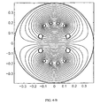
- Figs. 4-A and 4-B show transverse sectional views of a coil assembly comprising an inner curled-sheet coil and an outer wire coil, and exemplary, synthetically-generated magnetic field lines illustrating the magnetic fields generated by the two coils.
- Fig. 4-A illustrates the magnetic field generated by the inner, curled-sheet coil
- Fig. 4-B illustrates the magnetic field generated by the outer, wire coil.
- the magnetic field lines correspond to a substantially central transverse plane passing through the measurement volume defined by the coil assembly.
- the magnetic field computation was performed for infinitely long longitudinal conductors arranged in the configuration shown in Figs. 4-A and 4-B, with the assumption that the transverse coil size is much smaller than the wavelength of the RF field.
- a frequency of 800 MHz corresponds to a wavelength of tens of centimeters, which is much larger than a typical transverse coil size on the order of 1 cm.
- Figs. 4-C and 4-D show transverse sectional views of a coil assembly comprising a prior art inner flat-sheet coil and a prior art outer wire coil.
- the inner coil is relatively flat, i.e. non-curled.
- the radius of curvature of the longitudinal conductors of the inner coil is equal to the overall transverse radius of the coil.
- Fig. 4-C illustrates the magnetic field generated by the inner flat-sheet coil
- Fig. 4-D illustrates the magnetic field generated by the outer wire coil.
- the illustrated magnetic field lines were computed using the infinite-conductor and small-coil-size assumptions described above for Figs. 4-A and 4-B.
- the notation "Prior Art" in Figs. 4-C and 4-D refers to the general coil configuration shown, rather than the particular magnetic field line computations illustrated in the figures.
- the relatively large surface area presented by the inner flat-sheet coil limits the penetration of the magnetic field generated by the outer wire coil into the measurement volume.
- the inner flat-sheet coil can significantly limit the sensitivity that can be achieved with the outer wire coil.
- the relatively sharp edges of the inner flat-sheet coil lead to the concentration of current at those edges. The current concentration leads to higher RF losses, and thus reduced sensitivity, for the inner flat-sheet coil.
- each longitudinal conductor 52a-d shown in Fig. 2-A is formed by a curled (rounded) sheet.
- the external boundary of each segment 52a-d has a quasi-circular shape, and does not include sharp edges.
- a quasi-circular shape includes circle that is not completely closed, such as a circle having a gap.
- a rounded edges around the windows and slots of coil 30a around measurement volume 36 allows reducing the RF power dissipated by coil 30a , as well as improving the RF field homogeneity within measurement volume 36.
- the RF current tends to concentrate at the sheet edges. This current concentration leads to increased RF power losses for applied RF pulses, and to decreased measurement sensitivities.
- the RF current is relatively evenly distributed. The relatively even current distribution leads to decreased power losses and increased measurement sensitivities.
- the increased coil efficiency achieved by rounding the coil edges can be traded-off for increased field homogeneity if desired. For example, increasing the overall transverse size of coil 30a can lead to reduced sensitivity for coil 30a, but also to increased homogeneity in the magnetic fields corresponding to both coils 30a-b.
- a suitable pattern is first cut by well-known methods into a flat sheet of a desired material or materials.
- the flat pattern is rolled around a glass or quartz tube to form the end rings 40a-b of coil 30a.
- the rolled coil now has a set of flat longitudinal sections or wings which are to be curled into longitudinal conductors 52a-d.
- the coil is inserted into a sheet-curling tool as described below, and the sheet-curling tool is used to curl each flat longitudinal section into a tubular conductor.
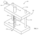
- Fig. 5 shows an isometric view of a sheet-curling tool 120 .
- Curling tool 120 comprises a support 124, and a longitudinal elongated curling member 130 mounted on support 124.
- Support 124 comprises two parallel, generally transverse plates 132a-b, two parallel longitudinal guides or rails 134a-b mounted on a lower plate 132b, and a height adjustment control 136 connected to an upper plate 132a.
- Two longitudinal apertures are defined through upper plate 132a. The apertures are sized to allow guides 134a-b to slide through upper plate 132a.
- Height adjustment control 136 is a screw capable of protruding through upper plate 132a and contacting guide 134a, thus locking upper plate 132a into place relative to lower plate 132b.
- Guides 134a-b are longer than the height of the coil to be manufactured.
- Curling member 130 can be removably mounted through upper plate 132a.
- Curling member 130 is shaped as an elongated cylinder, and has a thin longitudinal slot 150 extending from the proximal (top) of end of curling member 130 to the open distal (bottom) end of curling member 130.
- the width of slot 150 is chosen such that the sheet to be curled fits tightly through slot 150.
- the corresponding slot used for curling the sheet has a width of 0.004-0.005 inch.
- the diameter of curling member 130 is chosen to be equal to the desired diameter of the curled longitudinal coil conductors.
- a rotatable curling control or knob 170 is attached to curling member 130. Knob 170 is used to control the rotation of curling member 130 about its longitudinal axis.
- Coil 30a includes a sheet conductor rolled around a cylindrical glass support 60.
- the sheet conductor includes four flat longitudinal sections or wings extending from the rolled body. For clarity of presentation, the flat longitudinal sections are not shown in Fig. 5 .
- Curling member 130 is then inserted through upper plate 132a, and one of the flat longitudinal sections of coil 30a is inserted into slot 150 as curling member 130 is lowered into place. Curling member 130 is then rotated about its longitudinal axis, and the flat section of coil 30a is curled around the curling member. The transverse rings of coil 30a may be allowed to rotate during the curling step. After the flat section has been curled into a tube, the two longitudinal sides of the tube can be secured together using a drop of solder of adhesive. Curling member 130 is then removed vertically from the tube, coil 30a is rotated to place another flat section in position for curling, and the above process is repeated.
- a rounded-conductor coil of the present invention can be used in conjunction with a conventional orthogonal wire or sheet coil, or with another orthogonal rounded-conductor sheet coil.
- the orthogonal coil can be placed on the outside or on the inside of the rounded-conductor coil.
Landscapes
- Physics & Mathematics (AREA)
- Condensed Matter Physics & Semiconductors (AREA)
- General Physics & Mathematics (AREA)
- Magnetic Resonance Imaging Apparatus (AREA)
Description
- The invention in general relates to nuclear magnetic resonance (NMR), and in particular to radio-frequency (RF) coils for an NMR spectrometer.
- Nuclear magnetic resonance (NMR) spectrometers typically include a superconducting magnet for generating a static magnetic field B0, and one or more special-purpose radio-frequency (RF) coils for generating a time-varying magnetic field B1 perpendicular to the field B0, and for detecting the response of a sample to the applied magnetic fields. Each RF coil can resonate at the Larmor frequency of a nucleus of interest present in the sample. The RF coils are typically provided as part of an NMR probe, and are used to analyze samples situated in test tubes or flow cells. The direction of the static magnetic field B0 is commonly denoted as the z-axis, while the plane perpendicular to the z-axis is commonly termed the x-y or θ-plane. In the following discussion, the term "longitudinal" will be normally used to refer to the z-direction while the term "transverse" will be used to refer to the θ-direction.
- Conventional RF coils used for NMR include helical coils, saddle coils, resonant cavities, and birdcage resonators. For information on birdcage resonators see for example
U.S. Patent Nos. 4,692,705 ,6,236,206 , and6,285,189 . For information on saddle-shaped and other coils see for exampleU.S. Patent Nos. 4,398,149 ,4,388,601 ,4,517,516 ,4,641,098 ,4,840,700 ,5,192,911 ,5,818,232 , and6,201,392 . - The measurement sensitivity that can be achieved with an NMR coil increases with the coil quality factor Q and its filling factor n. The quality factor Q can be maximized by reducing coil losses. The filling factor n can be increased by reducing the coil size relative to the sample. At the same time, reducing the coil size relative to the sample can increase magnetic field inhomogeneities. Inhomogeneities in the RF magnetic field adversely affect the measurement sensitivity. Moreover, the coil design and dimensions are constrained by the requirement that the coil resonate in a desired frequency range. The resonant frequency of interest is determined by the nucleus of interest and the strength of the applied static magnetic field B0.
- The conducting parts of conventional coils are typically formed by wires having a round cross-section, or by conductive patterns formed from a thin sheet. Coils formed from sheets can have relatively high distributed capacitances, and thus relatively low inductances, for given coil sizes and resonant frequencies. The measurement sensitivities achievable with typical sheet-conductor coils can be limited by coil losses.
- An NMR probe can include multiple NMR coils, each tuned for performing NMR measurements on a different nucleus of interest. For example, an NMR probe can include one coil for performing NMR measurements on protons, and another coil for performing NMR measurements on other nuclei of interest, such as 13C or 15N. In such an NMR probe, the design of one coil can affect the performance of the other coil(s). In order to reduce the coupling between two coils, the coils can be disposed in a quadrature configuration, so that the magnetic fields generated by the coils are mutually orthogonal. This configuration minimizes the mutual inductance between the coils.
- The uniformity of the static and RF magnetic fields can be improved by employing susceptibility-compensated wires or sheets for the coil conductors. Abrupt changes in magnetic susceptibility near the sample can significantly degrade the field uniformity in the sample region. A susceptibility-compensated coil has an effective magnetic susceptibility roughly equal to that of the coil environment, which is commonly air or vacuum. A susceptibility-compensated sheet coil can be formed from a sandwich of two or more layers, wherein the materials and thicknesses of the layers are chosen to generate a desired effective susceptibility for the coil. For example, a paramagnetic layer and a diamagnetic layer can be stacked together to yield an effective susceptibility much lower in absolute value than the susceptibility of either layer alone. Effectively achieving susceptibility compensation can constrain RF coil thicknesses. For example, a relatively thin sheet may be required for achieving an effective coil susceptibility approaching zero. For further information on susceptibility-compensated NMR coils see for example
U.S. Patent Nos. 3,091,732 and6,054,855 . - As is apparent from the above discussion, the design of RF coils for NMR applications is highly constrained by multiple parameters. Maximizing the measurement sensitivity of an RF coil or coil assembly typically involves a balancing of effects of various design parameters. Coil designs providing increased design flexibility to the system designer would allow building NMR systems with increased sensitivities.
-
US 4,680,548 discloses a bird cage coil having two conductive loops at the upper and lower end of the coil wherein the conductive loops are formed of serially-connected capacitive elements. The upper and lower conductive loops of the coil are connected by longitudinal legs that represent inductive elements. The legs or axial conductive segments may be formed by wires, conducting tubes or flat conductive tapes having an inherent inductance in operation. Using thin conductive copper tubing for the legs is preferred to reduce losses and to get a better current distribution as compared to copper-clad printed circuit board or wires. -
US 4,878,022 proposes for the field of magnetic resonance imaging to use a curved edge coil conductor arranged in a housing of a table where a patient to be examined is lying. The use of curved edges of the conductive element avoids "hot spots" near the conductor surfaces. -
US 4641098 discloses an RF-coil as defined in the preamble of claim 1.EP 0856744 discloses a single-turn saddle coil including a floating inner ring for shielding the sample from parasitic RF fields. - The invention is defined in claim 1, respectively. Particular embodiments are set out in the dependent claims.
- The present invention provides radio-frequency coils for an NMR spectrometer allowing reduced RF losses, improved NMR measurement sensitivities, and improved magnetic field homogeneities. The longitudinal conductors and the ring-shaped conductors are formed from a single, preferably a susceptibility-compensated, sheet. The RF coil is a saddle-shaped coil. It can be provided as part of a coil assembly including an additional radio-frequency coil disposed orthogonally and concentrically with respect to the saddle-shaped coil.
- The ring-shaped conductors provide for relatively large distributed capacitances, while the rounded, i.e. almost closed hollow cylindrical, longitudinal conductors allow reducing coil losses and provide for increased transparency to orthogonal magnetic fields. Rounding the coil edges around the coil windows allows reducing the concentration of RF current at the coil edges, and thus reducing the RF losses within the coil. The reduced RF losses allow improved measurement sensitivities. The rounded shapes of the longitudinal conductors also allows increasing the transparency of the longitudinal conductors to the magnetic field generated by the additional, orthogonal coil.
- A sheet-curling tool comprising a rotatable, slotted longitudinal curling member allows the manufacture of the rounded-conductor coil from a single sheet. The curling member has a longitudinal slot extending along the member, for retaining a sheet conductor to be curled. The slot terminates in a distal open end at a longitudinal end of the curling member. The distal open end allows inserting and removing the sheet conductor longitudinally into/from the curling member. The curling member is mounted on a support comprising two longitudinally-spaced, generally transverse parallel plates. A pair of longitudinal guides is mounted on one of the plates. The longitudinal guides pass through corresponding apertures in the other plate, and allow the two plates to slide longitudinally to grip a patterned sheet in place between the plates. Once the sheet is secured, a wing of the patterned sheet is inserted into the longitudinal slot of the curling member, and the curling member is rotated about its longitudinal axis to curl the wing into a cylinder.
- The foregoing aspects and advantages of the present invention will become better understood upon reading the following detailed description and upon reference to the drawings where:
-
Fig. 1 is a schematic diagram of an NMR spectrometer according to the present invention. -
Fig. 2-A shows an isometric view of a conductive part of a rounded-conductor RF coil according to the present invention. -
Fig. 2-B shows an isometric view of a dielectric support for supporting the conductive part ofFig. 2-A . -
Fig. 3-A shows an isometric view of a saddle-shaped conductive part of a coil, suitable for use in conjunction with the coil illustrated inFig. 2-A . -
Fig. 3-B shows an isometric view of a support for supporting the conductive part ofFig. 3-A . -
Figs. 4-A and 4-B show central transverse views of a coil assembly including an inner coil such as the one shown inFig. 2-A , and computed magnetic fields generated by the inner and outer coil, respectively. -
Figs. 4-C and 4-D show central transverse views of a coil assembly including a prior art flat (non-curly) sheet inner coil and a prior art outer wire coil, and computed magnetic fields generated by the inner and outer coil, respectively. -
Fig. 5 shows an isometric view of a sheet-curling tool. - In the following description, the statement that a coil is mechanically coupled to a sample holder is understood to mean that the coil is held in fixed relation to the sample holder. Such a coil may be indirectly coupled to the target holder through intermediate support structures. The statement that a first coil is positioned orthogonally with respect to a second coil is understood to mean that the magnetic fields generated by the first and second coils are substantially orthogonal. The statement that a first coil is positioned concentrically with respect to the second coil is understood to mean that the two coils have substantially coincident longitudinal axes. The term "ring" is understood to encompass slotted (discontinuous) rings. The term "tube" is understood to encompass hollow tubes formed by curled sheets.
- The following description illustrates embodiments of the invention by way of example and not necessarily by way of limitation.
-
Fig. 1 is a schematic diagram illustrating a nuclear magnetic resonance (NMR)spectrometer 12 according to the present invention.Spectrometer 12 comprises amagnet 16, anNMR probe 20 inserted in a bore ofmagnet 16, and a control/acquisition system 18 electrically connected tomagnet 16 andprobe 20.Probe 20 includes a conventional sample holder or sample holding components for holding one NMR sample ofinterest 22 at a time while measurements are performed onsample 22.Probe 20 can be a flow-through probe or a stationary-sample. In a flow-through probe,sample 22 is typically held in a flow cell. In a stationary-sample probe,sample 22 is typically held in a test tube. -
Magnet 16 applies a static longitudinal magnetic field B0 to the samples. Control/acquisition system 18 comprises electronic components for applying desired radio-frequency pulses to probe 20, and acquiring data indicative of the nuclear magnetic resonance properties of the samples withinprobe 20.Probe 20 includes a coil assembly having one or more radio-frequency (RF) coils (resonators) 30a-b for applying transverse radio-frequency magnetic fields B1 to sample 22, and/or for measuring the response ofsample 22 to the applied magnetic fields. The same coil can be used for both applying an RF magnetic field and for measuring the sample response to the applied magnetic field. Alternatively, one coil may be used for applying an RF magnetic field, and another coil for measuring the response of the sample to the applied magnetic field. - Each
RF coil 30a-b is electromagnetically coupled to sample 22, and is electrically connected to control/acquisition system 18. RF coils 30a-b are preferably disposed concentrically relative to the longitudinal axis ofprobe 20. RF coils 30a-b are disposed mutually orthogonally, and generate mutually orthogonal transverse magnetic fields. EachRF coil 30a-b can be mounted on a support made of a material such as quartz or sapphire, chosen so as not to affect the NMR measurements of interest. - Each
RF coil 30a-b can have a different resonant frequency. For example, one ofcoils 30a-b can be tuned to perform 1H NMR measurements, while the other can be tuned to perform 13C NMR measurements.Coils 30a-b can be used in general to perform NMR measurement on other nuclei of interest, such as 19F and 31P. In a present implementation, an inner rounded-sheet coil 30a as described below is used to perform 1H NMR measurements, while an outerorthogonal wire coil 30b is used to perform 13C NMR measurements. In this implementation,outer wire coil 30b is a conventional saddle-shaped coil made of a susceptibility-compensated wire. -
Fig. 2-A shows an isometric view of the conductive part of a rounded-sheet radio-frequency (RF)coil 30a according to the present invention. The conductive part ofcoil 30a is mounted on acylindrical dielectric support 60, illustrated inFig. 2 -B. Referring back toFig. 2-A ,coil 30a includes an electrically-conductivecentral structure 32, and a pair of cylindrical conductive floatingshields 34a-b disposed on opposite longitudinal sides ofcentral structure 32. The central axis of eachshield 34a-b is aligned with the longitudinal central axis ofcentral structure 32. Ameasurement volume 36 is defined in the center ofcentral structure 32, betweenshields 34a-b. Themeasurement volume 36 sequentially accommodates NMR samples of interest held in cylindrical sample tubes or flow cells.Shields 34a-b are capacitively coupled tocentral structure 32 along at least part of the surfaces ofshields 34a-b adjacent tomeasurement volume 36.Shields 34a-b serve to reduce the parasitic excitation of the NMR samples due to RF pickup from coil leads or other conductive structures, and to shield the NMR samples from undesired external electric fields.Shields 34a-b also provide additional distributed capacitance tocoil 30a. -
Central structure 32 includes a pair of externallongitudinal leads 38a-b extending longitudinally away frommeasurement volume 36, toward the distal end ofshield 34a.Leads 38a-b provide an electrical connection to control/measurement electronics 18 (shown inFig. 1 ).Central structure 32 further includes a pair of ring-shaped transverse conductors (rings) 40a-b, and a set of four rounded-edgelongitudinal conductors 52a-d interconnecting rings 40a-b. -
Rings 40a-b are disposed on opposite sides ofmeasurement volume 36, and are disposed around the proximal ends ofshields 34a-b.Ring 40a has a pair oflongitudinal gaps 44a-b defined therethrough.Gaps 44a-b are situated on opposite sides ofring 40a.Gaps 44a-b extend along the entire longitudinal extent ofring 40a, so as to dividering 40a into separatearcuate ring sections 46a-b.Gaps 44a-b prevent the flow of current throughring 40a around a complete circle.Ring 40b has a pair oflongitudinal gaps 48a-b defined therethrough.Gaps 48a-b are situated on axially-opposite sides ofring 40b, substantially at 90° relative togaps 44a-b.Gaps 48a-b extend along the entire longitudinal extent ofring 40b, so as to dividering 40b intoseparate ring sections 50a-b.Gaps 48a-b prevent the flow of current throughring 40b around a complete circle. - A plurality of elongated, curled-sheet conductive longitudinal segments (rungs, conductors) 52a-d interconnect rings 40a-b.
Longitudinal segments 52a-d extend alongmeasurement volume 36 betweenrings 40a-b. Eachlongitudinal segment 52a-d is a tubular, almost closed hollow cylindrical, longitudinal conductor.Longitudinal segments 52a-b connect section 46a tosections 50a-b, respectively.Longitudinal segments 52c-d connect section 46b tosections 50a-b, respectively. - Preferably,
longitudinal segments 52a-d are situated transversely outward relative torings 40a-b, on the outside ofrings 40a-b. Eachsegment 52a-d curls outward, and the sign of the curvature of eachsegment 52a-d is preferably opposite that of its corresponding ring section 46, 50. The curvature of thesheet forming segments 52a-d and rings 40a-b changes sign at the interfaces betweensegments 52a-d and rings 40a-b. Thus,coil 30a has two regions of different curvatures: a transverse conductor region defined byrings 40a-b having a relatively large radius of curvature, and a longitudinal conductor region defined bysegments 52a-d having a smaller radius of curvature and an opposite curvature sign.Positioning segments 52a-d externally provides for relatively easy manufacture of the coil. Alternatively,longitudinal segments 52a-d may curl inward, and may be positioned on the internal side ofrings 40a-b. -
Rings 40a-b andsegments 52a-d form two loops facing each other along a transverse (x- or y-) direction, for generating an RFmagnetic field 54 along that direction. Current flows through the two loops in the same direction (clockwise or counterclockwise), such that the RF magnetic fields generated by the two loops reinforce each other. As an external voltage is applied overleads 38a-b, current flows fromlead 38a throughring section 46a,longitudinal segments 52a-b, throughring sections 50a-b,longitudinal segments 52c-d, andring section 46b to lead 38b. The current flow throughcoil 30a generates a transverse RF magnetic field illustrated inFig. 2-A by thearrow 54. -
Central structure 32, which includesrings 40a-b andlongitudinal conductors 52a-d, is formed from a single susceptibility-compensated thin sheet. In a present implementation,central structure 32 andshields 34a-b are made of susceptibility-compensated palladium-plated copper about 0.002 inches thick. In general, other materials such as aluminum, platinum, copper and stacks of such materials are suitable forcentral structure 32 andshields 34a-b. For example, an Al-Cu susceptibility-compensated sandwich may be used. Other materials having susceptibilities of opposite signs may be used to yield a magnetic susceptibility forcoil 30a equal to the magnetic susceptibility of air or vacuum. - In a present implementation, the overall transverse size of
rings 40a-b and shields 34a-b is on the order of I cm, and the transverse size of eachlongitudinal conductor 52a-b is about I mm. For typical NMR applications, transverse coil sizes forcoil 30a can range from a few millimeters to a few centimeters, and the transverse sizes oflongitudinal conductors 52a-b can range from tenths of mm to a few mm. The longitudinal extents oflongitudinal conductors 52a-b and rings 40a-b can be on order of a few cm. - The transverse size and radius of curvature of the tubular portion of each
longitudinal conductor 52a-d is preferably much smaller (e.g. less than 1/5, or less than 1/10) than the transverse size and radius of curvature ofrings 40a-b. At the same time, the radius of curvature of eachlongitudinal conductor 52a-d is larger than the thickness of the sheet forming the longitudinal conductor. Reducing the transverse size oflongitudinal conductors 52a-d allows an improvement in the sensitivity of the external,orthogonal RF coil 30b, by reducing the extent to whichlongitudinal conductors 52a-d obstruct the magnetic field generated by the external coil. At the same time, excessively reducing the transverse size of the boundary features oflongitudinal conductors 52a-d can lead to higher RF losses inlongitudinal conductors 52a-d, due to the concentration of RF current at any sharp edges oflongitudinal conductors 52a-d. -
Fig. 2-B shows an isometric view of adielectric coil support 60 suitable for supporting the conductive part ofcoil 30a.Support 60 is shaped as a hollow cylindrical shell, and has a longitudinal inner bore 66 for receiving the sample tubes or flow cells of interest. Inner bore 66 extends from the top end to the bottom end ofsupport 60.Support 60 has a longitudinalouter surface 62, and a longitudinalinner surface 64.Shields 34a-b (shown inFig. 2-A ) are attached to and abutinner surface 64.Rings 40a-b and leads 38a-b (shown inFig. 2-A ) are attached to and abutouter surface 62.Support 60 is preferably made of a dielectric material that does not interfere with NMR measurements, such as quartz or sapphire.Support 60 is secured at its longitudinal ends to the structure of theprobe containing coil 30a. - An alternative dielectric support for the conductive part of
coil 30a may include a plurality of thin longitudinal rods, each extending through and abutting the interior of one oflongitudinal conductors 52a-d. The rods may be supported by transverse end structures attached to an inner cylindrical dielectric support such as the one shown inFig. 2-B . Such rods may be useful for rollinglongitudinal conductors 52a-d around the rods during the manufacture ofcoil 30a. -
Fig. 3-A shows a schematic isometric view of the conductive part of a conventional multi-turn saddle-shapedRF coil 30b suitable for use in a coil assembly in conjunction withcoil 30a. The conductor ofFig. 3-A can be a conventional susceptibility-compensated saddle-shaped wire. The direction of the transverse RF magnetic field generated bycoil 30b is illustrated by thearrow 78. The magnetic field generated bycoil 30b is orthogonal to the magnetic field generated bycoil 30a. -
Fig. 3-B shows an isometric view of aconventional coil support 82 suitable for supporting the conductor ofcoil 30b.Coil support 82 includes two parallel transverse mountingplates 86a-b, and a plurality oflongitudinal rods 88 connecting mountingplates 86a-b. Mountingplates 86a-b have corresponding aligned central apertures defining aninternal coil space 90 for receivingcoil 30a and the sample of interest.Longitudinal rods 88 are arranged around the central apertures of mountingplates 86a-b. Each longitudinal conductor of the wire shown inFig. 3-A is attached to one of thelongitudinal rods 88 at one or more points. Mountingplates 86a-b are secured to the structure of theprobe containing coil 30b. -
Figs. 4-A and 4-B show transverse sectional views of a coil assembly comprising an inner curled-sheet coil and an outer wire coil, and exemplary, synthetically-generated magnetic field lines illustrating the magnetic fields generated by the two coils.Fig. 4-A illustrates the magnetic field generated by the inner, curled-sheet coil, whileFig. 4-B illustrates the magnetic field generated by the outer, wire coil. The magnetic field lines correspond to a substantially central transverse plane passing through the measurement volume defined by the coil assembly. The magnetic field computation was performed for infinitely long longitudinal conductors arranged in the configuration shown inFigs. 4-A and 4-B, with the assumption that the transverse coil size is much smaller than the wavelength of the RF field. For illustrative purposes, a frequency of 800 MHz corresponds to a wavelength of tens of centimeters, which is much larger than a typical transverse coil size on the order of 1 cm. -
Figs. 4-C and 4-D show transverse sectional views of a coil assembly comprising a prior art inner flat-sheet coil and a prior art outer wire coil. The inner coil is relatively flat, i.e. non-curled. The radius of curvature of the longitudinal conductors of the inner coil is equal to the overall transverse radius of the coil.Fig. 4-C illustrates the magnetic field generated by the inner flat-sheet coil, whileFig. 4-D illustrates the magnetic field generated by the outer wire coil. The illustrated magnetic field lines were computed using the infinite-conductor and small-coil-size assumptions described above forFigs. 4-A and 4-B. The notation "Prior Art" inFigs. 4-C and 4-D refers to the general coil configuration shown, rather than the particular magnetic field line computations illustrated in the figures. - As illustrated by
Fig. 4-D , the relatively large surface area presented by the inner flat-sheet coil limits the penetration of the magnetic field generated by the outer wire coil into the measurement volume. Thus, the inner flat-sheet coil can significantly limit the sensitivity that can be achieved with the outer wire coil. Moreover, the relatively sharp edges of the inner flat-sheet coil lead to the concentration of current at those edges. The current concentration leads to higher RF losses, and thus reduced sensitivity, for the inner flat-sheet coil. - According to the present invention, each
longitudinal conductor 52a-d shown inFig. 2-A is formed by a curled (rounded) sheet. As illustrated inFigs. 4-A and 4-B, the external boundary of eachsegment 52a-d has a quasi-circular shape, and does not include sharp edges. A quasi-circular shape includes circle that is not completely closed, such as a circle having a gap. - Referring back to
Fig. 2-A , providing rounded edges around the windows and slots ofcoil 30a aroundmeasurement volume 36 allows reducing the RF power dissipated bycoil 30a, as well as improving the RF field homogeneity withinmeasurement volume 36. In relatively flat sheets having sharp edges, the RF current tends to concentrate at the sheet edges. This current concentration leads to increased RF power losses for applied RF pulses, and to decreased measurement sensitivities. In rounded-edge coils, the RF current is relatively evenly distributed. The relatively even current distribution leads to decreased power losses and increased measurement sensitivities. The increased coil efficiency achieved by rounding the coil edges can be traded-off for increased field homogeneity if desired. For example, increasing the overall transverse size ofcoil 30a can lead to reduced sensitivity forcoil 30a, but also to increased homogeneity in the magnetic fields corresponding to bothcoils 30a-b. - To make
coil 30a, a suitable pattern is first cut by well-known methods into a flat sheet of a desired material or materials. The flat pattern is rolled around a glass or quartz tube to form the end rings 40a-b ofcoil 30a. The rolled coil now has a set of flat longitudinal sections or wings which are to be curled intolongitudinal conductors 52a-d. The coil is inserted into a sheet-curling tool as described below, and the sheet-curling tool is used to curl each flat longitudinal section into a tubular conductor. -
Fig. 5 shows an isometric view of a sheet-curlingtool 120.Curling tool 120 comprises asupport 124, and a longitudinal elongated curlingmember 130 mounted onsupport 124.Support 124 comprises two parallel, generallytransverse plates 132a-b, two parallel longitudinal guides orrails 134a-b mounted on alower plate 132b, and aheight adjustment control 136 connected to anupper plate 132a. Two longitudinal apertures are defined throughupper plate 132a. The apertures are sized to allowguides 134a-b to slide throughupper plate 132a.Height adjustment control 136 is a screw capable of protruding throughupper plate 132a and contactingguide 134a, thus lockingupper plate 132a into place relative to lowerplate 132b.Guides 134a-b are longer than the height of the coil to be manufactured. -
Curling member 130 can be removably mounted throughupper plate 132a.Curling member 130 is shaped as an elongated cylinder, and has a thinlongitudinal slot 150 extending from the proximal (top) of end of curlingmember 130 to the open distal (bottom) end of curlingmember 130. The width ofslot 150 is chosen such that the sheet to be curled fits tightly throughslot 150. For example, in a present implementation in which the sheet to be curled has a thickness of 0.002 inch, the corresponding slot used for curling the sheet has a width of 0.004-0.005 inch. The diameter of curlingmember 130 is chosen to be equal to the desired diameter of the curled longitudinal coil conductors. A rotatable curling control orknob 170 is attached to curlingmember 130.Knob 170 is used to control the rotation of curlingmember 130 about its longitudinal axis. - To start the operation of
sheet curling tool 120,control 136 is loosened andupper plate 132a is removed fromguides 134a-b.Coil 30a is then positioned ontolower plate 132b, andupper plate 132a is lowered ontoguides 134a-b.Coil 30a includes a sheet conductor rolled around acylindrical glass support 60. The sheet conductor includes four flat longitudinal sections or wings extending from the rolled body. For clarity of presentation, the flat longitudinal sections are not shown inFig. 5 . Whencoil 30a is secured betweenplates 132a-b,control 136 is screwed intoupper plate 132a to prevent the longitudinal motion ofupper plate 132a relative tolower plate 132b. -
Curling member 130 is then inserted throughupper plate 132a, and one of the flat longitudinal sections ofcoil 30a is inserted intoslot 150 as curlingmember 130 is lowered into place.Curling member 130 is then rotated about its longitudinal axis, and the flat section ofcoil 30a is curled around the curling member. The transverse rings ofcoil 30a may be allowed to rotate during the curling step. After the flat section has been curled into a tube, the two longitudinal sides of the tube can be secured together using a drop of solder of adhesive.Curling member 130 is then removed vertically from the tube,coil 30a is rotated to place another flat section in position for curling, and the above process is repeated. - A rounded-conductor coil of the present invention can be used in conjunction with a conventional orthogonal wire or sheet coil, or with another orthogonal rounded-conductor sheet coil. The orthogonal coil can be placed on the outside or on the inside of the rounded-conductor coil.
Claims (7)
- A radio-frequency coil for an NMR probe to be inserted into a bore of an NMR spectrometer magnet, the coil comprising:a) an electrically-conductive central structure (32) which is formed from a single conductive sheet, has a central longitudinal axis and comprises(i) a pair of ring-shaped conductors (40a,b) disposed at opposite longitudinal ends of the central structure, each ring-shaped conductor having a cylindrical shape about said axis and being divided by a pair of longitudinally extending gaps (44a,b; 48a,b) into two separate arcuate ring sections (46a,b; 50a,b), the two gaps of each ring-shaped conductor being spaced 180° apart from each other about said axis, the gaps (44a,b) of one ring being offset about said axis by substantially 90° relative to the gaps (48a,b) of the other ring; and(ii) two pairs of mutually parallel, elongated longitudinal conductors (52a-d) extending along said longitudinal axis and electrically interconnecting said arcuate ring sections of one ring-shaped conductor with those of the other, whereby each of the arcuate ring sections (46a,b) of one of the ring-shaped conductors (40a) electrically interconnects one of the pairs of longitudinal conductors (52a-d) and each of the arcuate ring sections (50a,b) of the other ring-shaped conductor (40b) electrically interconnects one longitudinal conductor from one of the pairs of longitudinal conductors with a longitudinal conductor from the other pair of longitudinal conductors;b) and a pair of cylindrical conductive floating shields (34a,b) disposed on opposite longitudinal ends of the electrically-conductive central structure, the central axis of each shield being aligned with said longitudinal axis, each shield being capacitively coupled to one of the ring-shaped conductors along a portion of the shield positioned inside the ring-shaped conductor;characterized in that
each of the longitudinal conductors has an almost closed hollow cylindrical shape, the radius of curvature of each of the longitudinal conductors being smaller than the radius of curvature of the ring-shaped conductors. - The coil of claim 1, wherein the single conductive sheet is susceptibility-compensated.
- The coil of claim 1, wherein each of the longitudinal conductors (52a-d) is situated radially outward relative to the ring-shaped conductors (40a,b).
- The coil of claim 1, wherein the radius of curvature of each of the longitudinal conductors (52a-d) is at least a factor of five smaller than the radius of curvature of the ring-shaped conductors (40a,b).
- The coil of claim 1, wherein the arcuate ring sections (46a,b; 48a,b) are attached to the radially outer surface of a longitudinally extending, hollow cylindrical dielectric support (60).
- A radio-frequency coil assembly for an NMR probe to be inserted into a bore of an NMR spectrometer magnet, the coil assembly comprising a first radio-frequency coil as defined in any one of claims 1-5 and a second radio-frequency coil (30b) for applying an RF magnetic field to a sample contained in a measuring volume surrounded by said electrically-conductive central structure of said first radio-frequency coil which is orthogonal to the RF magnetic field generated by said central structure itself.
- An NMR spectrometer for performing NMR measurements on a sample (22), comprising:- a magnet (16) for applying a static magnetic field, to the sample along a longitudinal direction; and- a radio-frequency coil as defined in any one of claims 1-5, or a radio-frequency coil assembly as defined in claim 6, wherein the central longitudinal axis of the electrically-conductive central structure (32) is parallel to said longitudinal direction.
Applications Claiming Priority (3)
| Application Number | Priority Date | Filing Date | Title |
|---|---|---|---|
| US35299 | 2001-10-26 | ||
| US10/035,299 US6593743B2 (en) | 2001-10-26 | 2001-10-26 | Rounded-conductor NMR RF resonators |
| PCT/US2002/031852 WO2003038460A1 (en) | 2001-10-26 | 2002-10-04 | Rounded-conductor nmr rf resonators |
Publications (2)
| Publication Number | Publication Date |
|---|---|
| EP1442311A1 EP1442311A1 (en) | 2004-08-04 |
| EP1442311B1 true EP1442311B1 (en) | 2010-02-10 |
Family
ID=21881795
Family Applications (1)
| Application Number | Title | Priority Date | Filing Date |
|---|---|---|---|
| EP02773718A Expired - Lifetime EP1442311B1 (en) | 2001-10-26 | 2002-10-04 | Rounded-conductor nmr rf resonator |
Country Status (5)
| Country | Link |
|---|---|
| US (1) | US6593743B2 (en) |
| EP (1) | EP1442311B1 (en) |
| JP (1) | JP2005508004A (en) |
| DE (1) | DE60235316D1 (en) |
| WO (1) | WO2003038460A1 (en) |
Families Citing this family (15)
| Publication number | Priority date | Publication date | Assignee | Title |
|---|---|---|---|---|
| AU2002951096A0 (en) | 2002-08-30 | 2002-09-12 | The University Of Queensland | A rotary phased array coil for magnetic resonance imaging |
| DE10249239A1 (en) * | 2002-10-23 | 2004-05-06 | Philips Intellectual Property & Standards Gmbh | Magnetic resonance imaging device with additional electrical equipment |
| US6917201B2 (en) * | 2002-12-09 | 2005-07-12 | Varian, Inc. | Squashed liquid NMR sample tubes and RF coils |
| US7092085B1 (en) * | 2004-01-20 | 2006-08-15 | Desa Richard J | Sample holder with intense magnetic field |
| US7064549B1 (en) * | 2005-01-18 | 2006-06-20 | Varian, Inc. | NMR RF coils with split movable capacitance bands |
| JP2007263621A (en) * | 2006-03-27 | 2007-10-11 | Kobe Steel Ltd | Coil for magnetic resonance detection and manufacturing method thereof |
| US7714581B2 (en) * | 2006-04-19 | 2010-05-11 | Wisconsin Alumni Research Foundation | RF coil assembly for magnetic resonance imaging and spectroscopy systems |
| US7508212B2 (en) | 2007-03-22 | 2009-03-24 | Wisconsin Alumni Research Foundation | RF coil assembly and method for practicing magnetization transfer on magnetic resonance imaging and spectroscopy systems |
| US7446532B1 (en) * | 2007-07-18 | 2008-11-04 | Varian, Inc. | Arched saddle-shaped NMR RF coils |
| US8164336B1 (en) * | 2007-11-10 | 2012-04-24 | Murphree Jr Dennis Haaga | Transmission line probe for NMR |
| US7557578B1 (en) * | 2008-08-29 | 2009-07-07 | Varian, Inc. | Low loss NMR sample holder |
| US9110132B2 (en) * | 2011-08-05 | 2015-08-18 | Chris Chiodo | Electrical and fluid connection system for magnetic imaging |
| KR102324731B1 (en) * | 2014-09-19 | 2021-11-10 | 삼성전자주식회사 | Receiving coil for magnetic resonance imaging device |
| CN113075600B (en) * | 2021-03-10 | 2022-12-30 | 华东师范大学 | Nuclear magnetic resonance radio frequency probe circuit and nuclear magnetic resonance radio frequency probe energy discharge method |
| CA3217440A1 (en) * | 2021-05-20 | 2022-11-24 | Klemens Kessler | Birdcage resonator for high resolution nmr applications |
Family Cites Families (19)
| Publication number | Priority date | Publication date | Assignee | Title |
|---|---|---|---|---|
| NL127050C (en) | 1958-06-05 | 1968-05-15 | ||
| US4398149A (en) | 1981-02-02 | 1983-08-09 | Varian Associates, Inc. | NMR Probe coil system |
| US4388601A (en) | 1981-09-30 | 1983-06-14 | Varian Associates, Inc. | Symmetrizing means for RF coils in a microwave cavity |
| US4517516A (en) | 1983-04-08 | 1985-05-14 | Varian Associates, Inc. | NMR Probe coil form structure |
| US4840700A (en) | 1983-11-02 | 1989-06-20 | General Electric Company | Current streamline method for coil construction |
| US4692705A (en) | 1983-12-23 | 1987-09-08 | General Electric Company | Radio frequency field coil for NMR |
| US4680548A (en) | 1984-10-09 | 1987-07-14 | General Electric Company | Radio frequency field coil for NMR |
| US4641098A (en) | 1985-03-15 | 1987-02-03 | Doty Scientific, Inc. | Parallel single turn saddle resonator for nuclear magnetic resonance signal reception |
| US4878022A (en) | 1988-10-14 | 1989-10-31 | The Regents Of The University Of California | Widened and shaped MRI surface coil having increased signal-to-noise ratio |
| US5192911A (en) | 1991-08-07 | 1993-03-09 | Varian Associates, Inc. | NMR probe incorporating RF shielding of sample |
| DE69227096T2 (en) | 1991-08-07 | 1999-02-25 | Varian Associates, Inc., Palo Alto, Calif. | Magnetic nuclear magnetic resonance probe with high-frequency shielding of the probe. |
| US5818232A (en) | 1997-04-17 | 1998-10-06 | Varian Associates, Inc. | Saddle-shaped multiturn RF coils for NMR probe |
| US6054855A (en) | 1997-11-07 | 2000-04-25 | Varian, Inc. | Magnetic susceptibility control of superconducting materials in nuclear magnetic resonance (NMR) probes |
| US6201392B1 (en) | 1997-11-07 | 2001-03-13 | Varian, Inc. | Coplanar RF probe coil arrangement for multifrequency excitation |
| US6252403B1 (en) * | 1998-04-21 | 2001-06-26 | The Trustees Of The University Of Pennsylvania | Spiral volume coil for improved radio frequency field homogeneity at high static magnetic field strength |
| US6236206B1 (en) | 1999-04-23 | 2001-05-22 | Varian, Inc. | Globally tunable birdcage coil and method for using same |
| US6285189B1 (en) | 1999-09-04 | 2001-09-04 | Varian, Inc. | Millipede coils |
| US6369570B1 (en) * | 2000-12-21 | 2002-04-09 | Varian, Inc. | B1 gradient coils |
| US6420871B1 (en) * | 2001-03-02 | 2002-07-16 | Varian, Inc. | Multiple tuned birdcage coils |
-
2001
- 2001-10-26 US US10/035,299 patent/US6593743B2/en not_active Expired - Lifetime
-
2002
- 2002-10-04 WO PCT/US2002/031852 patent/WO2003038460A1/en not_active Ceased
- 2002-10-04 JP JP2003540676A patent/JP2005508004A/en active Pending
- 2002-10-04 EP EP02773718A patent/EP1442311B1/en not_active Expired - Lifetime
- 2002-10-04 DE DE60235316T patent/DE60235316D1/en not_active Expired - Lifetime
Also Published As
| Publication number | Publication date |
|---|---|
| US6593743B2 (en) | 2003-07-15 |
| EP1442311A1 (en) | 2004-08-04 |
| JP2005508004A (en) | 2005-03-24 |
| WO2003038460A1 (en) | 2003-05-08 |
| US20030080740A1 (en) | 2003-05-01 |
| DE60235316D1 (en) | 2010-03-25 |
Similar Documents
| Publication | Publication Date | Title |
|---|---|---|
| US7068034B2 (en) | Squashed liquid NMR sample tubes and RF coils | |
| EP0141383B1 (en) | Radio frequency field coil for nmr | |
| EP0142760B1 (en) | Inductively coupled multi-section radio frequency field coil for nmr | |
| US6593743B2 (en) | Rounded-conductor NMR RF resonators | |
| US9274199B2 (en) | NMR RF probe coil exhibiting double resonance | |
| EP0151745A2 (en) | Radio frequency field coil for NMR | |
| EP1839066B1 (en) | Nmr rf coils with improved low-frequency efficiency | |
| US4680548A (en) | Radio frequency field coil for NMR | |
| EP0201084A2 (en) | A local probe for use in NMR imaging | |
| EP2618170A1 (en) | Sinusoidally resonant radio frequency volume coils for high field magnetic resonance applications | |
| EP0803737A2 (en) | Radio frequency coils | |
| EP0177855B1 (en) | Radio frequency field coil for nmr | |
| US7446532B1 (en) | Arched saddle-shaped NMR RF coils | |
| US8766636B2 (en) | MRI short coils | |
| WO2006078409A2 (en) | Nmr rf coils with split movable capacitance bands | |
| GB2151791A (en) | RF Field coils for NMR apparatus | |
| US7420371B2 (en) | Slab-selective RF coil for MR system | |
| US6452393B1 (en) | Nuclear magnetic resonance birdcage coil with Cassinian oval former | |
| US20130328564A1 (en) | Nmr rf probe coil exhibiting double resonance | |
| US6366093B1 (en) | Re-entrant RF cavity resonator for magnetic resonance | |
| Crozier et al. | Currents and fields in shielded RF resonators for NMR/MRI | |
| Hudson et al. | Open access birdcage coils for microscopic imaging of plants at 11.7 T | |
| Gimi et al. | Investigation of NMR signal-to-noise ratio for RF scroll microcoils |
Legal Events
| Date | Code | Title | Description |
|---|---|---|---|
| PUAI | Public reference made under article 153(3) epc to a published international application that has entered the european phase |
Free format text: ORIGINAL CODE: 0009012 |
|
| 17P | Request for examination filed |
Effective date: 20040519 |
|
| AK | Designated contracting states |
Kind code of ref document: A1 Designated state(s): AT BE BG CH CY CZ DE DK EE ES FI FR GB GR IE IT LI LU MC NL PT SE SK TR |
|
| RIN1 | Information on inventor provided before grant (corrected) |
Inventor name: DE SWIET, THOMAS |
|
| 17Q | First examination report despatched |
Effective date: 20090306 |
|
| GRAP | Despatch of communication of intention to grant a patent |
Free format text: ORIGINAL CODE: EPIDOSNIGR1 |
|
| RTI1 | Title (correction) |
Free format text: ROUNDED-CONDUCTOR NMR RF RESONATOR |
|
| GRAS | Grant fee paid |
Free format text: ORIGINAL CODE: EPIDOSNIGR3 |
|
| GRAA | (expected) grant |
Free format text: ORIGINAL CODE: 0009210 |
|
| AK | Designated contracting states |
Kind code of ref document: B1 Designated state(s): DE FR GB |
|
| REG | Reference to a national code |
Ref country code: GB Ref legal event code: FG4D |
|
| REF | Corresponds to: |
Ref document number: 60235316 Country of ref document: DE Date of ref document: 20100325 Kind code of ref document: P |
|
| PLBE | No opposition filed within time limit |
Free format text: ORIGINAL CODE: 0009261 |
|
| STAA | Information on the status of an ep patent application or granted ep patent |
Free format text: STATUS: NO OPPOSITION FILED WITHIN TIME LIMIT |
|
| 26N | No opposition filed |
Effective date: 20101111 |
|
| PGFP | Annual fee paid to national office [announced via postgrant information from national office to epo] |
Ref country code: FR Payment date: 20101105 Year of fee payment: 9 |
|
| PGFP | Annual fee paid to national office [announced via postgrant information from national office to epo] |
Ref country code: GB Payment date: 20101025 Year of fee payment: 9 |
|
| REG | Reference to a national code |
Ref country code: GB Ref legal event code: 732E Free format text: REGISTERED BETWEEN 20110324 AND 20110330 |
|
| REG | Reference to a national code |
Ref country code: FR Ref legal event code: TP |
|
| REG | Reference to a national code |
Ref country code: DE Ref legal event code: R081 Ref document number: 60235316 Country of ref document: DE Owner name: AGILENT TECHNOLOGIES, INC., SANTA CLARA, US Free format text: FORMER OWNER: VARIAN, INC., PALO ALTO, CALIF., US Effective date: 20110418 |
|
| GBPC | Gb: european patent ceased through non-payment of renewal fee |
Effective date: 20111004 |
|
| REG | Reference to a national code |
Ref country code: FR Ref legal event code: ST Effective date: 20120629 |
|
| PG25 | Lapsed in a contracting state [announced via postgrant information from national office to epo] |
Ref country code: FR Free format text: LAPSE BECAUSE OF NON-PAYMENT OF DUE FEES Effective date: 20111102 Ref country code: GB Free format text: LAPSE BECAUSE OF NON-PAYMENT OF DUE FEES Effective date: 20111004 |
|
| REG | Reference to a national code |
Ref country code: DE Ref legal event code: R082 Ref document number: 60235316 Country of ref document: DE Representative=s name: BARTH, DANIEL, DIPL.-ING., DE |
|
| PGFP | Annual fee paid to national office [announced via postgrant information from national office to epo] |
Ref country code: DE Payment date: 20150929 Year of fee payment: 14 |
|
| REG | Reference to a national code |
Ref country code: DE Ref legal event code: R119 Ref document number: 60235316 Country of ref document: DE |
|
| PG25 | Lapsed in a contracting state [announced via postgrant information from national office to epo] |
Ref country code: DE Free format text: LAPSE BECAUSE OF NON-PAYMENT OF DUE FEES Effective date: 20170503 |