EP0856744A1 - MMR probe incorporating RF shielding of sample - Google Patents
MMR probe incorporating RF shielding of sample Download PDFInfo
- Publication number
- EP0856744A1 EP0856744A1 EP98105087A EP98105087A EP0856744A1 EP 0856744 A1 EP0856744 A1 EP 0856744A1 EP 98105087 A EP98105087 A EP 98105087A EP 98105087 A EP98105087 A EP 98105087A EP 0856744 A1 EP0856744 A1 EP 0856744A1
- Authority
- EP
- European Patent Office
- Prior art keywords
- coil
- sample
- inner coil
- shielding
- lead means
- Prior art date
- Legal status (The legal status is an assumption and is not a legal conclusion. Google has not performed a legal analysis and makes no representation as to the accuracy of the status listed.)
- Granted
Links
- 239000000523 sample Substances 0.000 title description 33
- 230000005284 excitation Effects 0.000 claims description 7
- 239000002904 solvent Substances 0.000 description 8
- 230000000694 effects Effects 0.000 description 6
- 230000005855 radiation Effects 0.000 description 6
- 230000003071 parasitic effect Effects 0.000 description 5
- 238000001228 spectrum Methods 0.000 description 5
- 238000005481 NMR spectroscopy Methods 0.000 description 4
- 230000003595 spectral effect Effects 0.000 description 4
- 230000006872 improvement Effects 0.000 description 3
- 230000004044 response Effects 0.000 description 3
- 230000008901 benefit Effects 0.000 description 2
- 239000002131 composite material Substances 0.000 description 2
- 238000005259 measurement Methods 0.000 description 2
- 238000012545 processing Methods 0.000 description 2
- 230000001629 suppression Effects 0.000 description 2
- 230000009466 transformation Effects 0.000 description 2
- 230000001052 transient effect Effects 0.000 description 2
- 238000012935 Averaging Methods 0.000 description 1
- COLNVLDHVKWLRT-QMMMGPOBSA-N L-phenylalanine Chemical compound OC(=O)[C@@H](N)CC1=CC=CC=C1 COLNVLDHVKWLRT-QMMMGPOBSA-N 0.000 description 1
- 238000004458 analytical method Methods 0.000 description 1
- 238000009529 body temperature measurement Methods 0.000 description 1
- 230000015556 catabolic process Effects 0.000 description 1
- 239000004020 conductor Substances 0.000 description 1
- 230000008878 coupling Effects 0.000 description 1
- 238000010168 coupling process Methods 0.000 description 1
- 238000005859 coupling reaction Methods 0.000 description 1
- 238000006731 degradation reaction Methods 0.000 description 1
- 238000013461 design Methods 0.000 description 1
- 238000005315 distribution function Methods 0.000 description 1
- 230000009977 dual effect Effects 0.000 description 1
- 230000006698 induction Effects 0.000 description 1
- 238000011835 investigation Methods 0.000 description 1
- 230000000873 masking effect Effects 0.000 description 1
- 239000000463 material Substances 0.000 description 1
- 238000000034 method Methods 0.000 description 1
- COLNVLDHVKWLRT-UHFFFAOYSA-N phenylalanine Natural products OC(=O)C(N)CC1=CC=CC=C1 COLNVLDHVKWLRT-UHFFFAOYSA-N 0.000 description 1
- 230000000717 retained effect Effects 0.000 description 1
Images


Classifications
-
- G—PHYSICS
- G01—MEASURING; TESTING
- G01R—MEASURING ELECTRIC VARIABLES; MEASURING MAGNETIC VARIABLES
- G01R33/00—Arrangements or instruments for measuring magnetic variables
- G01R33/20—Arrangements or instruments for measuring magnetic variables involving magnetic resonance
- G01R33/28—Details of apparatus provided for in groups G01R33/44 - G01R33/64
- G01R33/32—Excitation or detection systems, e.g. using radio frequency signals
- G01R33/34—Constructional details, e.g. resonators, specially adapted to MR
- G01R33/343—Constructional details, e.g. resonators, specially adapted to MR of slotted-tube or loop-gap type
-
- G—PHYSICS
- G01—MEASURING; TESTING
- G01R—MEASURING ELECTRIC VARIABLES; MEASURING MAGNETIC VARIABLES
- G01R33/00—Arrangements or instruments for measuring magnetic variables
- G01R33/20—Arrangements or instruments for measuring magnetic variables involving magnetic resonance
- G01R33/28—Details of apparatus provided for in groups G01R33/44 - G01R33/64
- G01R33/42—Screening
- G01R33/422—Screening of the radio frequency field
Definitions
- the invention is in the field of nuclear magnetic resonance apparatus and particularly relates to improvements in RF probe structure.
- the signal-to-noise ratio In studies of high resolution NMR phenomena one limiting characteristic is the signal-to-noise ratio.
- the noise has a diverse origin and includes sources other than simple stochastic contributions. It is known that leads of the RF coil may serve as sources of parasitic radiation which may affect a sample under investigation.
- the present work is predicated upon improvements to RF probe performance incident to incorporating structure having the effect of eliminating, in the sensitive volume of the apparatus, RF signal pick-up originating from coil leads and otherwise shielding the sample from discontinuities of the termination of the coil itself (end effects).
- the polarizing field of the NMR apparatus is carefully shimmed to provide for the highest achievable uniformity in the central region of the RF coil where the coil design provides for application of the desired irradiation.
- the sample is ordinarily of extended dimension along one axis to avoid discontinuity in this sensitive volume, but sample regions removed from the center region of the sensitive volume may experience a significantly different polarizing field and therefore resonate at a different frequency. Steps taken to suppress solvent excitation in the center region of the sensitive volume may be ineffective against spurious excitation from coil leads near the ends of the sample. A broad resonance, shifted from the solvent peak can result, masking relatively weak intensity spectral features in this region.
- Tile effect of parasitic RF irradiation from coil leads is especially important in such situations where solvent suppression is required to observe spectral lines close to solvent resonances.
- solvent line(s) With low sample concentration, e.g., 10 -3 the solvent line(s) are inherently about 10 6 times as intense as the lines under study. Measures taken for suppression of a solvent resonance assume that such measures (saturation, for example) are ideally achieved. Where the sample has physical extension in regions beyond the sensitive volume and close to coil leads, even very weak radiation of the solvent (in the end portion) of the sensitive volume is sufficient to produce an undesired signal contribution.
- shielding of the sample of coil leads is accomplished with shielding comprising a floating conductive guard cylinder and/or an end cover or disk.
- the invention provides an RF coil structure as claimed in claim 1.
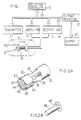
- FIG. 1 Portions of a typical NMR data acquisition instrument are schematically illustrated in FIG. 1.
- An acquisition/control processor 10 communicates with an RF transmitter 12, modulator 14 and receiver 16, including analog-to-digital convertor 18 and a further digital processor 20.
- Tile modulated RF power irradiates an object 23 in a magnetic field 21 through a probe assembly 22 and response of the object is intercepted by probe 22 communicating with receiver 16.
- the response typically takes the form of a transient time domain waveform or free induction decay. This transient waveform is sampled at regular intervals and samples are digitized in adc 18.
- the digitized time domain wave form is then subject to further processing in processor 20.
- processing may include averaging the time domain waveform over a number of similar of such waveforms and transformation of the average time domain wave form to the frequency domain yields a spectral distribution function directed to output device 24.
- this procedure may thus be repeated with variation of some other parameter and the transformation(s) from the data set may take on any of a number of identities for display or further analysis.
- the magnetic field 21 which polarizes the sample and defines the Larmor frequency thereof, is established by an appropriate means, not shown.
- Saddle coil(s) 19 are employed for imposing a desired spacial and time dependence of magnetic field.
- FIG. 2 there is shown a single turn saddle coil incorporating the invention.
- a particular coil structure comprises a ring 30 and ring 32, the latter segmented by gaps 38 and 38'. Rings 30 and 32 are connected by paraxial conductors 34 and 36. Leads 40 and 40' provide the feed from an RF source, e.g. transmitter 12 modulator 14. To this structure there is added a floating inner ring 42, closed off by closure disk 44 proximate to the leads 40 and 40'. A sample tube disposed on the axis of the coil is therefore shielded from parasitic radiation from leads 40 and 40' and from the edge effects of the end 46 of ring 32 of the coil.
- Mechanical support (not shown) for the saddle coil of FIG. 2 may be provided by an insulating cylindrical tube or a plurality of small diameter rods as described in U.S. 4,517,516.
- the floating ring is preferably supported directly from the interior of ring 32, or independently supported.
- temperature control of the sample is accomplished by flow of a controlled temperature gas stream about the sample.
- Complete closure of the floating ring 42 with disk 44 would prevent or reduce passage of the gas stream in the portion of the sample adjacent the floating ring 42.
- the disk 44 may be provided with perforations or the closure may employ a mesh material.
- a chimney 45 may be adapted to provide gas flow through closure disk 44' as in FIG. 2(b). The chimney 45 serves to provide the required shielding of the sample from RF leads.
- the axial extension of ring 42 may extend beyond the termination of ring 32 by an amount sufficient to assure acceptable shielding.
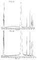
- FIG 3a The effect of the closure of the floating ring 42 with disk 44 is illustrated in FIG 3a (without closure disk 44) and FIG. 3b (with closure disk 44) for a sample of phenylalanine in 90% H 2 O-10% D 2 O.
- Closure disk 44 contained perforations for temperature control as discussed above.
- the spectral response of the instrument in the region close to the solvent peak and particularly from 1700 to 2700 MHz is particularly illustrative of the effect of the shielding
- Shielding of the sample from parasitic radiation may occur in other contexts as well Consider typical composite coil structures comprising quadrature coils or coaxial coils.
- an inner coil 50 is employed for 13 C excitation and the outer coil 52 for 1 H excitation.
- the probe may be of a type in which, for example, the inner coil 50 may be completely idle while the outer coil 52 is active. Nevertheless, it has been found that the presence of the inner coil 50 (specifically, its leads) 51-51' provides a medium for re-radiation (of the proton radiation) on portions of the axially disposed sample (not shown) proximate the inner coil leads 51-51'.
- FIG. 5(a) and FIG. 5(b) compare spectra of the identical sample in a dual (coaxial) coil structure without (FIG. 5(a), and equipped with (FIG. 5(b)) the floating ring.
Landscapes
- Physics & Mathematics (AREA)
- Condensed Matter Physics & Semiconductors (AREA)
- General Physics & Mathematics (AREA)
- Health & Medical Sciences (AREA)
- Epidemiology (AREA)
- Magnetic Resonance Imaging Apparatus (AREA)
Abstract
Description
Claims (2)
- An RF coil structure for applying an RF magnetic field to a sample disposed within the RF coil structure, comprising an inner coil (50) having lead means (51,51') for connecting the inner coil with an RF source, and an outer coil (52) mounted coaxially with the inner coil (5a), characterised by an electrically floating shield (54) mounted around the exterior of the inner coil (50), the shield (54) being arranged such that, when said inner coil (50) is idle and the outer coil (52) is active, re-radiation from the lead means (51,51') of the inner coil (50) on portions of the axially disposed sample proximate the lead means (51,51') is reduced.
- An RF coil according to claim 1, wherein the inner coil (50) is for 13C excitation, and the outer coil is for 1H excitation.
Applications Claiming Priority (3)
| Application Number | Priority Date | Filing Date | Title |
|---|---|---|---|
| US74172191A | 1991-08-07 | 1991-08-07 | |
| US741721 | 1991-08-07 | ||
| EP92916864A EP0551488B1 (en) | 1991-08-07 | 1992-07-29 | Nmr probe incorporation rf shielding of sample |
Related Parent Applications (1)
| Application Number | Title | Priority Date | Filing Date |
|---|---|---|---|
| EP92916864A Division EP0551488B1 (en) | 1991-08-07 | 1992-07-29 | Nmr probe incorporation rf shielding of sample |
Publications (2)
| Publication Number | Publication Date |
|---|---|
| EP0856744A1 true EP0856744A1 (en) | 1998-08-05 |
| EP0856744B1 EP0856744B1 (en) | 2003-09-24 |
Family
ID=24981892
Family Applications (2)
| Application Number | Title | Priority Date | Filing Date |
|---|---|---|---|
| EP98105087A Expired - Lifetime EP0856744B1 (en) | 1991-08-07 | 1992-07-29 | NMR probe incorporating RF shielding of sample |
| EP92916864A Expired - Lifetime EP0551488B1 (en) | 1991-08-07 | 1992-07-29 | Nmr probe incorporation rf shielding of sample |
Family Applications After (1)
| Application Number | Title | Priority Date | Filing Date |
|---|---|---|---|
| EP92916864A Expired - Lifetime EP0551488B1 (en) | 1991-08-07 | 1992-07-29 | Nmr probe incorporation rf shielding of sample |
Country Status (4)
| Country | Link |
|---|---|
| EP (2) | EP0856744B1 (en) |
| JP (1) | JP3430473B2 (en) |
| DE (2) | DE69227096T2 (en) |
| WO (1) | WO1993003390A1 (en) |
Cited By (1)
| Publication number | Priority date | Publication date | Assignee | Title |
|---|---|---|---|---|
| WO2003038460A1 (en) * | 2001-10-26 | 2003-05-08 | Varian, Inc. | Rounded-conductor nmr rf resonators |
Families Citing this family (2)
| Publication number | Priority date | Publication date | Assignee | Title |
|---|---|---|---|---|
| JP2002085373A (en) * | 2000-09-14 | 2002-03-26 | Ge Medical Systems Global Technology Co Llc | Method for inhibiting electromagnetic coupling between coils, orthogonal coil, mri device and method of making orthogonal coil |
| US7102350B2 (en) | 2004-06-30 | 2006-09-05 | General Electric Company | Shielding apparatus for magnetic resonance imaging |
Citations (2)
| Publication number | Priority date | Publication date | Assignee | Title |
|---|---|---|---|---|
| DE3621107A1 (en) * | 1985-06-26 | 1987-01-08 | Toshiba Kawasaki Kk | MAGNETIC RESONANCE IMAGING DEVICE |
| US4871969A (en) * | 1988-12-22 | 1989-10-03 | General Electric Company | RF shield for RF coil contained within gradient coils of NMR imaging device |
Family Cites Families (10)
| Publication number | Priority date | Publication date | Assignee | Title |
|---|---|---|---|---|
| FR2140744A5 (en) * | 1971-06-07 | 1973-01-19 | Thomson Csf | |
| EP0047065B1 (en) * | 1980-08-29 | 1986-10-01 | Technicare Corporation | Distributed phase rf coil |
| US4613820A (en) * | 1984-04-06 | 1986-09-23 | General Electric Company | RF shielded room for NMR imaging system |
| JPS61126456A (en) * | 1984-11-26 | 1986-06-13 | Mitsubishi Electric Corp | Detector for high-frequency magnetic field generation |
| NL8600730A (en) * | 1986-03-21 | 1987-10-16 | Philips Nv | MAGNETIC RESONANCE DEVICE WITH INTERFERENCE-FREE RF COIL. |
| DE3725718A1 (en) | 1987-08-04 | 1989-02-16 | Bruker Analytische Messtechnik | SAMPLE HEAD FOR NMR SPECTROMETER |
| US4879515A (en) * | 1988-12-22 | 1989-11-07 | General Electric Company | Double-sided RF shield for RF coil contained within gradient coils of NMR imaging device |
| JPH03147305A (en) * | 1989-11-01 | 1991-06-24 | Mitsubishi Electric Corp | Electromagnet provided with magnetic shield |
| US5017872A (en) * | 1990-01-19 | 1991-05-21 | General Electric Company | NMR radio frequency coil with dielectric loading for improved field homogeneity |
| JP3104880U (en) | 2003-09-12 | 2004-10-21 | 昭弘 神 | A curved mirror and the mounting position of the curved mirror for observing the vehicle diagonally behind |
-
1992
- 1992-07-29 DE DE69227096T patent/DE69227096T2/en not_active Expired - Lifetime
- 1992-07-29 JP JP50369893A patent/JP3430473B2/en not_active Expired - Lifetime
- 1992-07-29 EP EP98105087A patent/EP0856744B1/en not_active Expired - Lifetime
- 1992-07-29 EP EP92916864A patent/EP0551488B1/en not_active Expired - Lifetime
- 1992-07-29 DE DE1992633219 patent/DE69233219T2/en not_active Expired - Lifetime
- 1992-07-29 WO PCT/US1992/006275 patent/WO1993003390A1/en not_active Ceased
Patent Citations (2)
| Publication number | Priority date | Publication date | Assignee | Title |
|---|---|---|---|---|
| DE3621107A1 (en) * | 1985-06-26 | 1987-01-08 | Toshiba Kawasaki Kk | MAGNETIC RESONANCE IMAGING DEVICE |
| US4871969A (en) * | 1988-12-22 | 1989-10-03 | General Electric Company | RF shield for RF coil contained within gradient coils of NMR imaging device |
Non-Patent Citations (1)
| Title |
|---|
| D.A. ALDERMAN, D.M. GRANT: "An Efficient Decoupler Coil Design ...", JOURNAL OF MAGNETIC RESONANCE, vol. 36, 1979, pages 447 - 451, XP002064306 * |
Cited By (2)
| Publication number | Priority date | Publication date | Assignee | Title |
|---|---|---|---|---|
| WO2003038460A1 (en) * | 2001-10-26 | 2003-05-08 | Varian, Inc. | Rounded-conductor nmr rf resonators |
| US6593743B2 (en) | 2001-10-26 | 2003-07-15 | Varian, Inc. | Rounded-conductor NMR RF resonators |
Also Published As
| Publication number | Publication date |
|---|---|
| WO1993003390A1 (en) | 1993-02-18 |
| EP0551488A4 (en) | 1994-06-15 |
| JPH06504128A (en) | 1994-05-12 |
| DE69227096D1 (en) | 1998-10-29 |
| EP0551488B1 (en) | 1998-09-23 |
| DE69233219T2 (en) | 2004-07-08 |
| DE69227096T2 (en) | 1999-02-25 |
| JP3430473B2 (en) | 2003-07-28 |
| EP0551488A1 (en) | 1993-07-21 |
| DE69233219D1 (en) | 2003-10-30 |
| EP0856744B1 (en) | 2003-09-24 |
Similar Documents
| Publication | Publication Date | Title |
|---|---|---|
| US5192911A (en) | NMR probe incorporating RF shielding of sample | |
| US6696838B2 (en) | Nuclear magnetic resonance analysis of multiple samples | |
| US6593744B2 (en) | Multi-channel RF cable trap for magnetic resonance apparatus | |
| AU759922B2 (en) | Magnetic resonance detection coil that is immune to environmental noise | |
| US5262727A (en) | NMR probe | |
| US5581186A (en) | Bird cage resonator for high resolution nuclear magnetic resonance | |
| US6498487B1 (en) | Distributed capacitance inserts for NMR probes | |
| EP0047065A2 (en) | Distributed phase RF coil | |
| EP0551488B1 (en) | Nmr probe incorporation rf shielding of sample | |
| Rinard et al. | A wire‐crossed‐loop resonator for rapid scan EPR | |
| GB1150248A (en) | Coaxial Receiver Coil and Capacitor Structure for Probes of UHF Gyromagnetic Spectrometers. | |
| EP0312586B1 (en) | Spurious resonance control for nmr observe coils | |
| US6812703B2 (en) | Radio frequency NMR resonator with split axial shields | |
| US6011395A (en) | Shielded drive for balanced quadrature bird cage coil | |
| US20220206091A1 (en) | A coil assembly for mr imaging applications | |
| US6489768B1 (en) | Superconductive networks to optimize multiply tuned NMR coils | |
| WO1992017799A1 (en) | Rf saddle coil for use with pulsed magnetic fields | |
| AU2002301342B9 (en) | Magnetic Resonance |
Legal Events
| Date | Code | Title | Description |
|---|---|---|---|
| PUAI | Public reference made under article 153(3) epc to a published international application that has entered the european phase |
Free format text: ORIGINAL CODE: 0009012 |
|
| 17P | Request for examination filed |
Effective date: 19980407 |
|
| AC | Divisional application: reference to earlier application |
Ref document number: 551488 Country of ref document: EP |
|
| AK | Designated contracting states |
Kind code of ref document: A1 Designated state(s): DE FR NL |
|
| RIN1 | Information on inventor provided before grant (corrected) |
Inventor name: CUMMINGS, MICHAEL D. Inventor name: HILL, HOWARD D.W. |
|
| RAP1 | Party data changed (applicant data changed or rights of an application transferred) |
Owner name: VARIAN, INC. |
|
| 17Q | First examination report despatched |
Effective date: 20011012 |
|
| GRAH | Despatch of communication of intention to grant a patent |
Free format text: ORIGINAL CODE: EPIDOS IGRA |
|
| RTI1 | Title (correction) |
Free format text: NMR PROBE INCORPORATING RF SHIELDING OF SAMPLE |
|
| GRAH | Despatch of communication of intention to grant a patent |
Free format text: ORIGINAL CODE: EPIDOS IGRA |
|
| GRAA | (expected) grant |
Free format text: ORIGINAL CODE: 0009210 |
|
| AC | Divisional application: reference to earlier application |
Ref document number: 0551488 Country of ref document: EP Kind code of ref document: P |
|
| AK | Designated contracting states |
Kind code of ref document: B1 Designated state(s): DE FR NL |
|
| REF | Corresponds to: |
Ref document number: 69233219 Country of ref document: DE Date of ref document: 20031030 Kind code of ref document: P |
|
| ET | Fr: translation filed | ||
| PLBE | No opposition filed within time limit |
Free format text: ORIGINAL CODE: 0009261 |
|
| STAA | Information on the status of an ep patent application or granted ep patent |
Free format text: STATUS: NO OPPOSITION FILED WITHIN TIME LIMIT |
|
| 26N | No opposition filed |
Effective date: 20040625 |
|
| PGFP | Annual fee paid to national office [announced via postgrant information from national office to epo] |
Ref country code: NL Payment date: 20100724 Year of fee payment: 19 |
|
| PGFP | Annual fee paid to national office [announced via postgrant information from national office to epo] |
Ref country code: FR Payment date: 20100805 Year of fee payment: 19 Ref country code: DE Payment date: 20100728 Year of fee payment: 19 |
|
| REG | Reference to a national code |
Ref country code: FR Ref legal event code: TP |
|
| REG | Reference to a national code |
Ref country code: NL Ref legal event code: SD Effective date: 20110714 |
|
| REG | Reference to a national code |
Ref country code: DE Ref legal event code: R082 Ref document number: 69233219 Country of ref document: DE Representative=s name: KAHLER, KAECK & MOLLEKOPF, DE |
|
| REG | Reference to a national code |
Ref country code: DE Ref legal event code: R082 Ref document number: 69233219 Country of ref document: DE Representative=s name: KAHLER KAECK MOLLEKOPF PARTNERSCHAFT VON PATEN, DE Effective date: 20111130 Ref country code: DE Ref legal event code: R082 Ref document number: 69233219 Country of ref document: DE Representative=s name: KAHLER, KAECK & MOLLEKOPF, DE Effective date: 20111130 Ref country code: DE Ref legal event code: R081 Ref document number: 69233219 Country of ref document: DE Owner name: AGILENT TECHNOLOGIES INC., SANTA CLARA, US Free format text: FORMER OWNER: VARIAN, INC., PALO ALTO, CALIF., US Effective date: 20111130 Ref country code: DE Ref legal event code: R081 Ref document number: 69233219 Country of ref document: DE Owner name: AGILENT TECHNOLOGIES INC., US Free format text: FORMER OWNER: VARIAN, INC., PALO ALTO, US Effective date: 20111130 |
|
| REG | Reference to a national code |
Ref country code: NL Ref legal event code: V1 Effective date: 20120201 |
|
| REG | Reference to a national code |
Ref country code: FR Ref legal event code: ST Effective date: 20120330 |
|
| PG25 | Lapsed in a contracting state [announced via postgrant information from national office to epo] |
Ref country code: DE Free format text: LAPSE BECAUSE OF NON-PAYMENT OF DUE FEES Effective date: 20120201 Ref country code: FR Free format text: LAPSE BECAUSE OF NON-PAYMENT OF DUE FEES Effective date: 20110801 |
|
| REG | Reference to a national code |
Ref country code: DE Ref legal event code: R119 Ref document number: 69233219 Country of ref document: DE Effective date: 20120201 |
|
| PG25 | Lapsed in a contracting state [announced via postgrant information from national office to epo] |
Ref country code: NL Free format text: LAPSE BECAUSE OF NON-PAYMENT OF DUE FEES Effective date: 20120201 |