EP1442154B1 - Procede de realisation d'un revetement continu a la surface d'une piece - Google Patents
Procede de realisation d'un revetement continu a la surface d'une piece Download PDFInfo
- Publication number
- EP1442154B1 EP1442154B1 EP02796837A EP02796837A EP1442154B1 EP 1442154 B1 EP1442154 B1 EP 1442154B1 EP 02796837 A EP02796837 A EP 02796837A EP 02796837 A EP02796837 A EP 02796837A EP 1442154 B1 EP1442154 B1 EP 1442154B1
- Authority
- EP
- European Patent Office
- Prior art keywords
- coating
- layer
- support
- continuity
- chemical vapor
- Prior art date
- Legal status (The legal status is an assumption and is not a legal conclusion. Google has not performed a legal analysis and makes no representation as to the accuracy of the status listed.)
- Expired - Lifetime
Links
Images


Classifications
-
- C—CHEMISTRY; METALLURGY
- C23—COATING METALLIC MATERIAL; COATING MATERIAL WITH METALLIC MATERIAL; CHEMICAL SURFACE TREATMENT; DIFFUSION TREATMENT OF METALLIC MATERIAL; COATING BY VACUUM EVAPORATION, BY SPUTTERING, BY ION IMPLANTATION OR BY CHEMICAL VAPOUR DEPOSITION, IN GENERAL; INHIBITING CORROSION OF METALLIC MATERIAL OR INCRUSTATION IN GENERAL
- C23C—COATING METALLIC MATERIAL; COATING MATERIAL WITH METALLIC MATERIAL; SURFACE TREATMENT OF METALLIC MATERIAL BY DIFFUSION INTO THE SURFACE, BY CHEMICAL CONVERSION OR SUBSTITUTION; COATING BY VACUUM EVAPORATION, BY SPUTTERING, BY ION IMPLANTATION OR BY CHEMICAL VAPOUR DEPOSITION, IN GENERAL
- C23C16/00—Chemical coating by decomposition of gaseous compounds, without leaving reaction products of surface material in the coating, i.e. chemical vapour deposition [CVD] processes
- C23C16/44—Chemical coating by decomposition of gaseous compounds, without leaving reaction products of surface material in the coating, i.e. chemical vapour deposition [CVD] processes characterised by the method of coating
- C23C16/458—Chemical coating by decomposition of gaseous compounds, without leaving reaction products of surface material in the coating, i.e. chemical vapour deposition [CVD] processes characterised by the method of coating characterised by the method used for supporting substrates in the reaction chamber
- C23C16/4581—Chemical coating by decomposition of gaseous compounds, without leaving reaction products of surface material in the coating, i.e. chemical vapour deposition [CVD] processes characterised by the method of coating characterised by the method used for supporting substrates in the reaction chamber characterised by material of construction or surface finish of the means for supporting the substrate
-
- C—CHEMISTRY; METALLURGY
- C23—COATING METALLIC MATERIAL; COATING MATERIAL WITH METALLIC MATERIAL; CHEMICAL SURFACE TREATMENT; DIFFUSION TREATMENT OF METALLIC MATERIAL; COATING BY VACUUM EVAPORATION, BY SPUTTERING, BY ION IMPLANTATION OR BY CHEMICAL VAPOUR DEPOSITION, IN GENERAL; INHIBITING CORROSION OF METALLIC MATERIAL OR INCRUSTATION IN GENERAL
- C23C—COATING METALLIC MATERIAL; COATING MATERIAL WITH METALLIC MATERIAL; SURFACE TREATMENT OF METALLIC MATERIAL BY DIFFUSION INTO THE SURFACE, BY CHEMICAL CONVERSION OR SUBSTITUTION; COATING BY VACUUM EVAPORATION, BY SPUTTERING, BY ION IMPLANTATION OR BY CHEMICAL VAPOUR DEPOSITION, IN GENERAL
- C23C14/00—Coating by vacuum evaporation, by sputtering or by ion implantation of the coating forming material
- C23C14/04—Coating on selected surface areas, e.g. using masks
- C23C14/046—Coating cavities or hollow spaces, e.g. interior of tubes; Infiltration of porous substrates
-
- Y—GENERAL TAGGING OF NEW TECHNOLOGICAL DEVELOPMENTS; GENERAL TAGGING OF CROSS-SECTIONAL TECHNOLOGIES SPANNING OVER SEVERAL SECTIONS OF THE IPC; TECHNICAL SUBJECTS COVERED BY FORMER USPC CROSS-REFERENCE ART COLLECTIONS [XRACs] AND DIGESTS
- Y10—TECHNICAL SUBJECTS COVERED BY FORMER USPC
- Y10S—TECHNICAL SUBJECTS COVERED BY FORMER USPC CROSS-REFERENCE ART COLLECTIONS [XRACs] AND DIGESTS
- Y10S427/00—Coating processes
- Y10S427/10—Chemical vapor infiltration, i.e. CVI
Definitions
- the invention relates to the realization of a continuous coating on the surface of a workpiece.
- the field of application of the invention is more particularly the formation of a protective coating on parts made of a material that is sensitive to oxidation corrosion and / or the formation of a coating for sealing parts made of a porous material. refractory.
- the materials concerned are typically carbon, graphite and thermostructural composite materials such as carbon / carbon (C / C) composites and ceramic matrix composites with carbon fiber reinforcement (for example composites (C / SiC) or with fiber reinforcement ceramic (eg SiC / SiC), carbon can then be present at an interphase between ceramic fibers and ceramic matrix.
- C / C carbon / carbon
- ceramic matrix composites with carbon fiber reinforcement for example composites (C / SiC) or with fiber reinforcement ceramic (eg SiC / SiC)
- carbon fiber reinforcement ceramic eg SiC / SiC
- the formation of a continuous coating on the outer surface of parts made of such materials is necessary to ensure them good resistance in an oxidizing medium at high temperature, and / or to seal their surface, materials such as carbon, graphite and especially thermostructural composites with a greater or lesser internal porosity.
- a coating layer may be formed by a gaseous route optionally combined with a liquid route (mixed route).
- the gaseous route consists of chemical vapor deposition or infiltration.
- a gas containing at least one precursor of the material of the coating to be produced is brought into contact with the workpiece under conditions of temperature and pressure which favor the formation of this material by decomposition of the precursor or reaction between several constituents thereof.
- the deposition of the coating material also occurs within the porosity of the material of the workpiece and a surface coating is formed after filling the porosity at least in the vicinity of the surface.
- the liquid route consists of coating the surface of the workpiece with a precursor liquid of the coating material, typically a resin optionally containing a solvent and a filler. After crosslinking, the conversion of the precursor is obtained by heat treatment. The formation of the coating is completed by gas.
- a precursor liquid of the coating material typically a resin optionally containing a solvent and a filler.
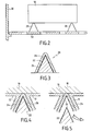
- the part is usually placed on one or more supports with limited contact between the part and the or each support.
- the material of the formed coating 1 is deposited on the part 2 and on the supports 3, as shown very schematically in FIG. Figure 1A and, in more detail, the Figure 1B .
- the rupture that occurs leaves on the part an unprotected zone 4 ( figure 1C ), especially when the material of the part, such as graphite, has a lower mechanical strength than that of the coating material, such as silicon carbide (SiC).
- the solution generally adopted consists in producing a second coating layer 5 ( figure 1D ) by replacing the workpiece on the supports after returning it.
- the object of the invention is to provide a method for producing a continuous coating on the entire surface of a placed part on one or more supports, without having to resort to two successive deposits of the coating material and without risk of creating a defect in the coating during the separation between the part and the support or supports.
- the separation layer is made of a material with a laminated structure, the separation between the support and the part being made by cleavage within this material.
- the material of the separation layer may be chosen from laminar pyrolytic carbon, hexagonal boron nitride, laminated graphite or silicoaluminous materials with a lamellar structure, such as talc or clays.
- the continuity layer may be formed on the or each support, above the separation layer.
- the continuity layer comes into contact with the workpiece when it is placed on the or each support and remains on the surface of the workpiece when the support or supports are removed with rupture within the separation layer.
- the continuity layer may alternatively be formed locally on the part, at least at the level of the support zones.
- the continuity layer is made of a material similar to that of the coating to be produced.
- a prior surface treatment of the continuity layer is advantageously carried out to promote adhesion with the coating material. This surface treatment may be a heat treatment or acid attack treatment.
- the continuity layer is made of a porous material.
- the coating is then produced by chemical vapor infiltration, with at least partial densification of the porous material of the continuity layer.
- a first embodiment of a method according to the invention will be described below in the context of the formation, by chemical vapor infiltration, of a continuous coating of silicon carbide (SiC) over the entire surface of a graphite part, to protect it from oxidation.
- SiC silicon carbide
- the graphite part to be coated is placed on supports 20 inside a chemical vapor infiltration oven. Several pieces can be loaded simultaneously in the oven, on different trays 32.
- the SiC coating is obtained using a gas phase which may contain methyltrichlorosilane (MTS) as precursor of SiC. Methods and facilities for the formation of SiC deposits by chemical vapor infiltration are well known. We can refer to the document EP 0 256 073 .
- the supports 20 have a conical or pyramidal shape providing at their summit a zone of limited surface contact with the part 10.
- Other forms of supports are conceivable, for example prismatic bars having a limited contact surface along a surface. fish bone.
- each support 20 comprises a substrate 22 made of refractory material, for example graphite or thermostructural composite material such as a composite material C / C, and an outer layer 24 of silicon carbide intended to form a continuity layer of the SiC coating to achieve.
- a separating layer 26 of refractory material having a lower mechanical strength than the SiC of the layer 24 is interposed between the substrate 22 and the layer 24.
- the separation layer 26 defines a weakening zone. It is advantageously a material with a lamellar structure, or cleavable material, such as pyrolytic carbon (PyC) of the laminar type, hexagonal boron nitride (BN), laminated graphite or other refractory material such as lamellar silicoaluminous materials, such as talc or clays.
- a material with a lamellar structure, or cleavable material such as pyrolytic carbon (PyC) of the laminar type, hexagonal boron nitride (BN), laminated graphite or other refractory material such as lamellar silicoaluminous materials, such as talc or clays.
- a layer of PyC or BN can be obtained by deposition or chemical vapor infiltration.
- a layer of BN or laminated graphite may also be obtained by spraying (then spraying) and optionally smoothing according to a known technique used in particular to form a release agent layer on the wall of a mold, for example with the product based on BN of the French company "ACHESON FRANCE" marketed under the name “Puisé Aéro A”, or the product to graphite base of the same company marketed under the name “Graphoil D31A”.
- a layer of talc or clay may also be obtained by spraying in finely divided form and then by smoothing.
- the thickness of the layer 26 must be sufficient to subsequently allow separation by rupture within this layer, without damage to the layer 24 of SiC.
- This thickness must however remain relatively limited to ensure sufficient adhesion of the outer layer 24 until final separation.
- the thickness of the layer 26 is preferably chosen between 0.1 micron and 20 microns, typically between 0.5 micron and 5 microns.
- the SiC layer 24 is formed by chemical vapor deposition or infiltration. Its thickness is chosen at least equal to that of the coating to be formed on the part 10.
- an SiC coating 12 is formed on the part 10 and on the exposed lateral faces of the supports 20, as shown in detail in FIG. figure 4 .
- the part 10 is removed from the oven with the supports 20, then the supports 20 are physically separated from the part 10. Due to the presence of the weakening layer 26, the separation between the support and the part is done within it, as shown by the figure 5 .
- the continuity of the SiC coating on the part is ensured, at the level of the area of contact with a support, by the layer 24 of the support which remains attached to the part 10.
- the excess layer portion 24 can then optionally be removed by machining ( see the broken line 16 on the figure 5 ), so that a continuous SiC coating having a substantially constant thickness is formed over the entire surface of the workpiece 10.
- the layer 24 is preferably made by a chemical vapor infiltration process similar to that used for the coating 12, so as to obtain SiC deposits of same structure.
- a surface treatment can be carried out on the surface of the outer layer 24, so that to remove any impurity and / or a silica film (SiO 2 ) that would have formed, to facilitate a bond with strong adhesion with the coating 12.
- Such a surface treatment may consist of a heat treatment, for example at a temperature of 1200 ° C. to 1900 ° C. under secondary vacuum.
- a silica film is removed by reaction with SiC, i.e. SiC + 2SiO 2 ⁇ 3SiO + CO.
- the surface treatment is acid etching, for example hydrofluoric acid (HF) also to remove the surface SiO 2 film.
- acid etching for example hydrofluoric acid (HF) also to remove the surface SiO 2 film.
- a continuous protective coating against oxidation of a part made at least in part of carbon or graphite may be made of a refractory ceramic material chosen in particular from carbides, other than SiC, and nitrides.
- the reactive gas used is chosen according to the nature of the coating to be formed. We can refer to the document FR 2 401 888 for example, which describes the production of coatings of different types by infiltration or chemical vapor deposition.
- an outer layer and a separating layer on the part supports may be limited to the areas of the supports intended to be in contact with the parts.
- the figure 6 illustrates an alternative embodiment of a support 30 for a part to be coated.
- the support 30 comprises a substrate 32 of refractory material provided with a separation layer 36.
- the substrate 32 and the layer 36 are for example similar to the substrate 22 and to the layer 26 described above with reference to FIG. figure 3 .
- the support 30 differs from that 20 of the figure 3 in that it comprises an outer layer 34 of porous material, formed on the separation layer 36.
- the layer 34 is a layer intended for ensure the continuity of the subsequently formed coating on a part resting on the support 30.
- the porous layer 34 is for example made by depositing on the separation layer 36, at least in the upper part of the support 30, a liquid composition comprising a precursor of a material similar to that of the coating to be formed.
- the precursor is for example a polycarbosilane resin (PCS).
- PCS polycarbosilane resin
- Other precursors may be used, for example polycarbosiloxanes or silicones.
- the resin optionally added with a solvent to adjust the viscosity can be loaded with SiC powder. After coating, the resin is crosslinked and a ceramization is carried out by heat treatment.
- the part 10 to be coated is placed on one or more supports 30 and an SiC coating is formed by chemical vapor infiltration.
- the layer 34 is densified and a coating 12 is formed on the part 10.
- the infiltration is continued until filling the porosity, at least in the superficial part, of the layer 34 and development of a coating external 12 'on it, of less thickness than the coating 12.
- the removal of the support is by rupture within the separation layer 36.
- a continuous SiC coating is obtained over the entire surface of the part 10, the continuity at a support zone being provided by the continuity layer.
- 34 in SiC densified with SiC ( figure 8 ).
- FIG. 9 to 11 illustrate a variant of the process of Figures 6 to 8 .
- a porous continuity layer 14 is formed not on a separation layer 46 of one or more supports 40, but on the surface of the part 10.
- the layer 14 is formed on a part of the surface of the part 10, possibly in several separate parts, so as to be present at least at the or each zone of the supports.
- the support 40 is therefore supported by the separation layer 46 on the layer 14 ( figure 9 ).
- the material of the layer 14 may be identical to that of the layer 34 described above.
- the support 40 comprises a substrate 42 coated by the separation layer 46, the latter being similar to the substrate 22 and the separation layer 26 of the support 20 described above.
- An SiC coating is formed by chemical vapor infiltration.
- the porous layer 14 is densified while coatings 12 and 12 "are formed on the surface portions of the part not coated by the porous layer 14 and on the separation layer 46.
- the infiltration is carried out so as to fill the porosity of the layer 14, at least in its superficial part, and to develop an external coating 14 'on it, of a thickness less than that of the coating 12 ( figure 10 ).
- the removal of the support is by rupture within the separation layer.
- a continuous SiC coating is obtained over the entire surface of the part, the continuity at the or each support zone being obtained by the continuity layer 14 densified by SiC and provided with the coating 14 '(FIG. figure 11 ).
- the excess portion of coating 12 "can be optionally removed with flattening for example at the surface of the coating 14 '.
Landscapes
- Chemical & Material Sciences (AREA)
- Chemical Kinetics & Catalysis (AREA)
- Engineering & Computer Science (AREA)
- Materials Engineering (AREA)
- Mechanical Engineering (AREA)
- Metallurgy (AREA)
- Organic Chemistry (AREA)
- General Chemical & Material Sciences (AREA)
- Chemical Vapour Deposition (AREA)
- Physical Or Chemical Processes And Apparatus (AREA)
Applications Claiming Priority (3)
| Application Number | Priority Date | Filing Date | Title |
|---|---|---|---|
| FR0114313 | 2001-11-06 | ||
| FR0114313A FR2831892B1 (fr) | 2001-11-06 | 2001-11-06 | Procede de realisation d'un revetement continu a la surface d'une piece |
| PCT/FR2002/003775 WO2003040429A1 (fr) | 2001-11-06 | 2002-11-05 | Procede de realisation d'un revetement continu a la surface d'une piece |
Publications (2)
| Publication Number | Publication Date |
|---|---|
| EP1442154A1 EP1442154A1 (fr) | 2004-08-04 |
| EP1442154B1 true EP1442154B1 (fr) | 2011-01-19 |
Family
ID=8869094
Family Applications (1)
| Application Number | Title | Priority Date | Filing Date |
|---|---|---|---|
| EP02796837A Expired - Lifetime EP1442154B1 (fr) | 2001-11-06 | 2002-11-05 | Procede de realisation d'un revetement continu a la surface d'une piece |
Country Status (8)
Families Citing this family (13)
| Publication number | Priority date | Publication date | Assignee | Title |
|---|---|---|---|---|
| FR2850649B1 (fr) * | 2003-01-30 | 2005-04-29 | Snecma Propulsion Solide | Procede pour le traitement de surface d'une piece en materiau composite thermostructural et application au brasage de pieces en materiau composite thermostructural |
| CN101146935A (zh) * | 2005-01-24 | 2008-03-19 | 丹福斯有限公司 | 涂敷物体的方法 |
| WO2006113447A2 (en) * | 2005-04-14 | 2006-10-26 | Ted Johnson | Superabrasive coatings |
| US8039050B2 (en) * | 2005-12-21 | 2011-10-18 | Geo2 Technologies, Inc. | Method and apparatus for strengthening a porous substrate |
| US20170050890A1 (en) * | 2012-03-02 | 2017-02-23 | Dynamic Material Systems, LLC | Advanced Mirrors Utilizing Polymer-Derived-Ceramic Mirror Substrates |
| US9764987B2 (en) | 2012-03-02 | 2017-09-19 | Dynamic Material Systems, LLC | Composite ceramics and ceramic particles and method for producing ceramic particles and bulk ceramic particles |
| US10399907B2 (en) | 2012-03-02 | 2019-09-03 | Dynamic Material Systems, LLC | Ceramic composite structures and processing technologies |
| US11326255B2 (en) * | 2013-02-07 | 2022-05-10 | Uchicago Argonne, Llc | ALD reactor for coating porous substrates |
| FR3042993A1 (fr) | 2015-11-04 | 2017-05-05 | Commissariat Energie Atomique | Matrice et piston d'appareil de sps, appareil de sps les comprenant, et procede de frittage, densification ou assemblage sous une atmosphere oxydante utilisant cet appareil |
| JP7178209B2 (ja) * | 2018-08-22 | 2022-11-25 | 株式会社Uacj | 熱交換器の製造方法 |
| US11111578B1 (en) | 2020-02-13 | 2021-09-07 | Uchicago Argonne, Llc | Atomic layer deposition of fluoride thin films |
| US12065738B2 (en) | 2021-10-22 | 2024-08-20 | Uchicago Argonne, Llc | Method of making thin films of sodium fluorides and their derivatives by ALD |
| US11901169B2 (en) | 2022-02-14 | 2024-02-13 | Uchicago Argonne, Llc | Barrier coatings |
Citations (2)
| Publication number | Priority date | Publication date | Assignee | Title |
|---|---|---|---|---|
| EP0172082A1 (fr) * | 1984-07-20 | 1986-02-19 | SOCIETE EUROPEENNE DE PROPULSION (S.E.P.) Société Anonyme dite: | Procédé de fabrication d'un matériau composite à renfort fibreux réfractaire et matrice céramique, et structure telle qu'obtenue par ce procédé |
| WO1987004733A1 (fr) * | 1986-02-10 | 1987-08-13 | Societe Europeenne De Propulsion | Installation pour l'infiltration chimique en phase vapeur d'un materiau refractaire autre que le carbone |
Family Cites Families (6)
| Publication number | Priority date | Publication date | Assignee | Title |
|---|---|---|---|---|
| US4472476A (en) * | 1982-06-24 | 1984-09-18 | United Technologies Corporation | Composite silicon carbide/silicon nitride coatings for carbon-carbon materials |
| CA2065724A1 (en) * | 1991-05-01 | 1992-11-02 | Thomas R. Anthony | Method of producing articles by chemical vapor deposition and the support mandrels used therein |
| US5175929A (en) * | 1992-03-04 | 1993-01-05 | General Electric Company | Method for producing articles by chemical vapor deposition |
| US6231923B1 (en) * | 1998-08-17 | 2001-05-15 | Tevtech Llc | Chemical vapor deposition of near net shape monolithic ceramic parts |
| US6258227B1 (en) * | 1999-03-13 | 2001-07-10 | Applied Materials, Inc. | Method and apparatus for fabricating a wafer spacing mask on a substrate support chuck |
| US6659161B1 (en) * | 2000-10-13 | 2003-12-09 | Chien-Min Sung | Molding process for making diamond tools |
-
2001
- 2001-11-06 FR FR0114313A patent/FR2831892B1/fr not_active Expired - Fee Related
-
2002
- 2002-11-05 CA CA2433907A patent/CA2433907C/en not_active Expired - Fee Related
- 2002-11-05 US US10/250,419 patent/US6926925B2/en not_active Expired - Lifetime
- 2002-11-05 JP JP2003542671A patent/JP4286142B2/ja not_active Expired - Fee Related
- 2002-11-05 WO PCT/FR2002/003775 patent/WO2003040429A1/fr active Application Filing
- 2002-11-05 EP EP02796837A patent/EP1442154B1/fr not_active Expired - Lifetime
- 2002-11-05 DE DE60239007T patent/DE60239007D1/de not_active Expired - Lifetime
-
2003
- 2003-07-02 NO NO20033032A patent/NO20033032D0/no not_active Application Discontinuation
Patent Citations (2)
| Publication number | Priority date | Publication date | Assignee | Title |
|---|---|---|---|---|
| EP0172082A1 (fr) * | 1984-07-20 | 1986-02-19 | SOCIETE EUROPEENNE DE PROPULSION (S.E.P.) Société Anonyme dite: | Procédé de fabrication d'un matériau composite à renfort fibreux réfractaire et matrice céramique, et structure telle qu'obtenue par ce procédé |
| WO1987004733A1 (fr) * | 1986-02-10 | 1987-08-13 | Societe Europeenne De Propulsion | Installation pour l'infiltration chimique en phase vapeur d'un materiau refractaire autre que le carbone |
Also Published As
| Publication number | Publication date |
|---|---|
| US20040028813A1 (en) | 2004-02-12 |
| NO20033032L (no) | 2003-07-02 |
| FR2831892B1 (fr) | 2004-02-06 |
| CA2433907A1 (en) | 2003-05-15 |
| WO2003040429A1 (fr) | 2003-05-15 |
| DE60239007D1 (de) | 2011-03-03 |
| CA2433907C (en) | 2010-10-19 |
| EP1442154A1 (fr) | 2004-08-04 |
| FR2831892A1 (fr) | 2003-05-09 |
| JP4286142B2 (ja) | 2009-06-24 |
| NO20033032D0 (no) | 2003-07-02 |
| US6926925B2 (en) | 2005-08-09 |
| JP2005508448A (ja) | 2005-03-31 |
Similar Documents
| Publication | Publication Date | Title |
|---|---|---|
| EP1587773B1 (fr) | Procede pour le traitement de surface d une piece en materiau composite thermostructural et application au brasage de pieces en materiau composite thermostructural | |
| EP1442154B1 (fr) | Procede de realisation d'un revetement continu a la surface d'une piece | |
| EP0948469B1 (fr) | MATERIAU COMPOSITE A MATRICE CERAMIQUE ET RENFORT EN FIBRES SiC ET PROCEDE POUR SA FABRICATION | |
| EP0861218B1 (fr) | Procede pour l'introduction dans des substrats poreux d'une composition en fusion a base de silicium | |
| EP2785665B1 (fr) | Procede de fabrication de piece en materiau cmc | |
| EP0482994B1 (fr) | Pièce en matériau composite carboné, protégée contre l'oxydation et son procédé de fabrication | |
| EP2483073B1 (fr) | Piece en materiau composite a matrice ceramique et procede pour sa fabrication | |
| FR2732338A1 (fr) | Materiau composite protege contre l'oxydation par matrice auto-cicatrisante et son procede de fabrication | |
| EP2401245B1 (fr) | Dispositif comportant un tube céramique revetu et une frette | |
| FR3062336A1 (fr) | Procede de fabrication d'une piece en materiau composite | |
| EP0614808B1 (fr) | Procédé de fabrication d'éléments de protection thermique, en particulier pour avions spatiaux | |
| FR2747674A1 (fr) | Revetement de protection pour pieces d'oeuvre et son procede de realisation, pieces d'oeuvre presentant ce revetement de protection | |
| EP1888813B1 (fr) | Procede de densification rapide d'un substrat fibreux poreux par formation d'un depot solide au sein de la porosite du substrat | |
| WO2019058069A1 (fr) | Procede de fabrication d'une piece en cmc | |
| EP3227475B1 (fr) | Creuset réutilisable pour la fabrication de matériau cristallin | |
| FR2701256A1 (fr) | Procédé d'obtention d'un matériau céramique à base de Sialon par réduction d'un précurseur aluminosilicaté et application à la formation de revêtement céramique sur un substrat réfractaire. | |
| WO2015036975A1 (fr) | Substrat pour la solidification de lingot de silicium | |
| EP1391444A1 (fr) | Procédé de fabrication d'un materiau réfractaire, revêtement protecteur susceptible d'être obtenu par ce procédé et leurs utilisations | |
| FR3145934A1 (fr) | Procédés de jonction de composants composites pour former un composant composite unitaire | |
| FR3063500A1 (fr) | Procede de fabrication d'une piece revetue |
Legal Events
| Date | Code | Title | Description |
|---|---|---|---|
| PUAI | Public reference made under article 153(3) epc to a published international application that has entered the european phase |
Free format text: ORIGINAL CODE: 0009012 |
|
| 17P | Request for examination filed |
Effective date: 20030804 |
|
| AK | Designated contracting states |
Kind code of ref document: A1 Designated state(s): AT BE BG CH CY CZ DE DK EE ES FI FR GB GR IE IT LI LU MC NL PT SE SK TR |
|
| AX | Request for extension of the european patent |
Extension state: AL LT LV MK RO SI |
|
| GRAP | Despatch of communication of intention to grant a patent |
Free format text: ORIGINAL CODE: EPIDOSNIGR1 |
|
| GRAS | Grant fee paid |
Free format text: ORIGINAL CODE: EPIDOSNIGR3 |
|
| GRAA | (expected) grant |
Free format text: ORIGINAL CODE: 0009210 |
|
| AK | Designated contracting states |
Kind code of ref document: B1 Designated state(s): DE FR GB IE SE |
|
| REG | Reference to a national code |
Ref country code: GB Ref legal event code: FG4D Free format text: NOT ENGLISH |
|
| REG | Reference to a national code |
Ref country code: IE Ref legal event code: FG4D Free format text: LANGUAGE OF EP DOCUMENT: FRENCH |
|
| REF | Corresponds to: |
Ref document number: 60239007 Country of ref document: DE Date of ref document: 20110303 Kind code of ref document: P |
|
| REG | Reference to a national code |
Ref country code: DE Ref legal event code: R096 Ref document number: 60239007 Country of ref document: DE Effective date: 20110303 |
|
| REG | Reference to a national code |
Ref country code: SE Ref legal event code: TRGR |
|
| PLBE | No opposition filed within time limit |
Free format text: ORIGINAL CODE: 0009261 |
|
| STAA | Information on the status of an ep patent application or granted ep patent |
Free format text: STATUS: NO OPPOSITION FILED WITHIN TIME LIMIT |
|
| 26N | No opposition filed |
Effective date: 20111020 |
|
| PGFP | Annual fee paid to national office [announced via postgrant information from national office to epo] |
Ref country code: IE Payment date: 20111021 Year of fee payment: 10 |
|
| REG | Reference to a national code |
Ref country code: DE Ref legal event code: R097 Ref document number: 60239007 Country of ref document: DE Effective date: 20111020 |
|
| REG | Reference to a national code |
Ref country code: IE Ref legal event code: MM4A |
|
| PG25 | Lapsed in a contracting state [announced via postgrant information from national office to epo] |
Ref country code: IE Free format text: LAPSE BECAUSE OF NON-PAYMENT OF DUE FEES Effective date: 20121105 |
|
| REG | Reference to a national code |
Ref country code: FR Ref legal event code: PLFP Year of fee payment: 14 |
|
| REG | Reference to a national code |
Ref country code: FR Ref legal event code: PLFP Year of fee payment: 15 |
|
| REG | Reference to a national code |
Ref country code: DE Ref legal event code: R082 Ref document number: 60239007 Country of ref document: DE Representative=s name: CBDL PATENTANWAELTE, DE Ref country code: DE Ref legal event code: R081 Ref document number: 60239007 Country of ref document: DE Owner name: AIRBUS SAFRAN LAUNCHERS SAS, FR Free format text: FORMER OWNER: SNECMA PROPULSION SOLIDE, LE HAILLAN, FR |
|
| REG | Reference to a national code |
Ref country code: DE Ref legal event code: R082 Ref document number: 60239007 Country of ref document: DE Representative=s name: CBDL PATENTANWAELTE, DE Ref country code: DE Ref legal event code: R081 Ref document number: 60239007 Country of ref document: DE Owner name: AIRBUS SAFRAN LAUNCHERS SAS, FR Free format text: FORMER OWNER: HERAKLES, LE HAILLAN, FR |
|
| REG | Reference to a national code |
Ref country code: DE Ref legal event code: R082 Ref document number: 60239007 Country of ref document: DE Representative=s name: CBDL PATENTANWAELTE, DE Ref country code: DE Ref legal event code: R081 Ref document number: 60239007 Country of ref document: DE Owner name: AIRBUS SAFRAN LAUNCHERS SAS, FR Free format text: FORMER OWNER: SAFRAN CERAMICS, LE HAILLAN, FR |
|
| REG | Reference to a national code |
Ref country code: GB Ref legal event code: 732E Free format text: REGISTERED BETWEEN 20170914 AND 20170920 |
|
| REG | Reference to a national code |
Ref country code: FR Ref legal event code: PLFP Year of fee payment: 16 |
|
| REG | Reference to a national code |
Ref country code: FR Ref legal event code: CD Owner name: AIRBUS SAFRAN LAUNCHERS SAS, FR Effective date: 20171212 Ref country code: FR Ref legal event code: TP Owner name: AIRBUS SAFRAN LAUNCHERS SAS, FR Effective date: 20171212 |
|
| PGFP | Annual fee paid to national office [announced via postgrant information from national office to epo] |
Ref country code: FR Payment date: 20171123 Year of fee payment: 16 Ref country code: DE Payment date: 20171116 Year of fee payment: 16 |
|
| PGFP | Annual fee paid to national office [announced via postgrant information from national office to epo] |
Ref country code: GB Payment date: 20171121 Year of fee payment: 16 Ref country code: SE Payment date: 20171117 Year of fee payment: 16 |
|
| REG | Reference to a national code |
Ref country code: DE Ref legal event code: R119 Ref document number: 60239007 Country of ref document: DE |
|
| REG | Reference to a national code |
Ref country code: SE Ref legal event code: EUG |
|
| GBPC | Gb: european patent ceased through non-payment of renewal fee |
Effective date: 20181105 |
|
| PG25 | Lapsed in a contracting state [announced via postgrant information from national office to epo] |
Ref country code: SE Free format text: LAPSE BECAUSE OF NON-PAYMENT OF DUE FEES Effective date: 20181106 |
|
| PG25 | Lapsed in a contracting state [announced via postgrant information from national office to epo] |
Ref country code: FR Free format text: LAPSE BECAUSE OF NON-PAYMENT OF DUE FEES Effective date: 20181130 Ref country code: DE Free format text: LAPSE BECAUSE OF NON-PAYMENT OF DUE FEES Effective date: 20190601 |
|
| PG25 | Lapsed in a contracting state [announced via postgrant information from national office to epo] |
Ref country code: GB Free format text: LAPSE BECAUSE OF NON-PAYMENT OF DUE FEES Effective date: 20181105 |