EP1441863B1 - Fire suppression using water mist with ultrafine size droplets - Google Patents
Fire suppression using water mist with ultrafine size droplets Download PDFInfo
- Publication number
- EP1441863B1 EP1441863B1 EP02778285A EP02778285A EP1441863B1 EP 1441863 B1 EP1441863 B1 EP 1441863B1 EP 02778285 A EP02778285 A EP 02778285A EP 02778285 A EP02778285 A EP 02778285A EP 1441863 B1 EP1441863 B1 EP 1441863B1
- Authority
- EP
- European Patent Office
- Prior art keywords
- mist
- fire
- water
- fire suppression
- carrier medium
- Prior art date
- Legal status (The legal status is an assumption and is not a legal conclusion. Google has not performed a legal analysis and makes no representation as to the accuracy of the status listed.)
- Expired - Lifetime
Links
Images
Classifications
-
- A—HUMAN NECESSITIES
- A62—LIFE-SAVING; FIRE-FIGHTING
- A62C—FIRE-FIGHTING
- A62C5/00—Making of fire-extinguishing materials immediately before use
- A62C5/008—Making of fire-extinguishing materials immediately before use for producing other mixtures of different gases or vapours, water and chemicals, e.g. water and wetting agents, water and gases
-
- A—HUMAN NECESSITIES
- A62—LIFE-SAVING; FIRE-FIGHTING
- A62C—FIRE-FIGHTING
- A62C31/00—Delivery of fire-extinguishing material
-
- A—HUMAN NECESSITIES
- A62—LIFE-SAVING; FIRE-FIGHTING
- A62C—FIRE-FIGHTING
- A62C5/00—Making of fire-extinguishing materials immediately before use
-
- A—HUMAN NECESSITIES
- A62—LIFE-SAVING; FIRE-FIGHTING
- A62C—FIRE-FIGHTING
- A62C99/00—Subject matter not provided for in other groups of this subclass
- A62C99/0009—Methods of extinguishing or preventing the spread of fire by cooling down or suffocating the flames
- A62C99/0072—Methods of extinguishing or preventing the spread of fire by cooling down or suffocating the flames using sprayed or atomised water
-
- B—PERFORMING OPERATIONS; TRANSPORTING
- B05—SPRAYING OR ATOMISING IN GENERAL; APPLYING FLUENT MATERIALS TO SURFACES, IN GENERAL
- B05B—SPRAYING APPARATUS; ATOMISING APPARATUS; NOZZLES
- B05B17/00—Apparatus for spraying or atomising liquids or other fluent materials, not covered by the preceding groups
- B05B17/04—Apparatus for spraying or atomising liquids or other fluent materials, not covered by the preceding groups operating with special methods
- B05B17/06—Apparatus for spraying or atomising liquids or other fluent materials, not covered by the preceding groups operating with special methods using ultrasonic or other kinds of vibrations
- B05B17/0607—Apparatus for spraying or atomising liquids or other fluent materials, not covered by the preceding groups operating with special methods using ultrasonic or other kinds of vibrations generated by electrical means, e.g. piezoelectric transducers
- B05B17/0615—Apparatus for spraying or atomising liquids or other fluent materials, not covered by the preceding groups operating with special methods using ultrasonic or other kinds of vibrations generated by electrical means, e.g. piezoelectric transducers spray being produced at the free surface of the liquid or other fluent material in a container and subjected to the vibrations
-
- B—PERFORMING OPERATIONS; TRANSPORTING
- B05—SPRAYING OR ATOMISING IN GENERAL; APPLYING FLUENT MATERIALS TO SURFACES, IN GENERAL
- B05B—SPRAYING APPARATUS; ATOMISING APPARATUS; NOZZLES
- B05B7/00—Spraying apparatus for discharge of liquids or other fluent materials from two or more sources, e.g. of liquid and air, of powder and gas
- B05B7/0012—Apparatus for achieving spraying before discharge from the apparatus
-
- B—PERFORMING OPERATIONS; TRANSPORTING
- B05—SPRAYING OR ATOMISING IN GENERAL; APPLYING FLUENT MATERIALS TO SURFACES, IN GENERAL
- B05B—SPRAYING APPARATUS; ATOMISING APPARATUS; NOZZLES
- B05B7/00—Spraying apparatus for discharge of liquids or other fluent materials from two or more sources, e.g. of liquid and air, of powder and gas
- B05B7/02—Spray pistols; Apparatus for discharge
- B05B7/10—Spray pistols; Apparatus for discharge producing a swirling discharge
Definitions
- the present invention relates to suppression of fire by extremely fine droplet water mist and more particularly, but not by way of limitation, to an improved method and apparatus for producing an extremely fine sub-micron size water mist using an electronic ultrasonic device that produces the mist at ambient-pressure and delivering the mist for application in suppressing fire.
- Water mist has been reconsidered as a potential agent to replace halon gas.
- Water is environmentally friendly with no known toxic properties.
- Water has a specific heat of 4.18 J/g, and a high latent heat of vaporization of 2260 J/g that assist in cooling a flame.
- water is readily available and cost efficient.
- Water mist suppresses fire through different mechanisms. Each mechanism exhibits a different degree of influence on the overall suppression efficiency of a water mist.
- the four important operating mechanisms are heat extraction, oxygen displacement, radiant heat attenuation, and dilution of the vapor/air mixture. Heat extraction and cooling of the flame has the maximum effect on the efficiency of fire suppression and the other mechanisms usually supplement the heat extraction mechanism.
- the inventors have found through computer simulation and experimentation that the success of water mist in its application to fire suppression depends on the ability to produce nearly nanometer-scale and sub-micron size droplets of water mist and deliver the mist to various fire scenarios. Extremely small droplets vaporize instantaneously and absorb energy to extract heat from the flame. Water mist droplets of larger diameters vaporize more slowly and are not as efficient in suppressing fires. Also, larger droplets are not as easily entrained into the fire and need additional momentum if the mist has to be introduced away from the firebase.
- An extremely fine mist of sub-micron size water droplets avoids several of the disadvantages normally associated with the conventional water mist fire suppression technology. For instance, typical water mist applications having larger droplet size may cause a kinetic effect on flames causing flare-up from the water droplets striking the fuel surface. Further, because of slower vaporization and greater momentum needed, larger droplets wet surfaces within the area of application, conduct electricity and often damage items. Thus, a key to the success of water mist technology is the use of very fine nanometer-scale sub-micron water mist produced using a cost-effective and ambient-pressure method.
- pressurized systems are subject to leaks and hazards of bursting posed by retaining fluids under pressure.
- These systems require nozzles that are subject to clogging because of the small nozzle diameters and are also expensive and difficult to construct because of their precise specifications.
- the droplet size obtainable in these prior art systems is on the order of 50-200 microns.
- these droplets are effective in cooling the flame.
- the water mist droplets may still wet surfaces and cause electrical conductance. This limits the ability to use water mist fire suppression in computer and data center applications or in precious item preservation rooms in libraries and museums.
- the mechanical atomization technology required by conventional fine water mist fire suppression systems is still very expensive.
- the prior art mist generation methods for fire suppression involve well-documented methods such as pressurized water or twin-fluid atomizers.
- Single fluid pressure based atomizers use water stored or pumped at high pressure (40 to 200 bar) and spray nozzles with relatively small orifice sizes.
- Twin-fluid systems use air, nitrogen, or other gases to atomize water at a nozzle as described e.g. in later published U.S. Pat. No 6,390,203.
- an objective of this invention is to provide a water mist fire suppression method using an electronic ultrasonic device to produce a water mist having sub-micron diameter water droplets.
- Another objective of the invention is to provide a fire suppression device using an electronic ultrasonic device to produce a water mist and optionally powered by line fed electric power or a portable power source such as a battery.
- Another objective of the invention is to provide a fire suppression method using a mist generation method that does not need pressurized water or gas.
- Another objective of the invention is to use a method of generating mist for fire suppression that does not use an atomizing nozzle and is free from nozzle clogging and flow blockage.
- Another objective is to provide a device and method to deliver a sub-micron diameter mist to a fire such that the mist that is entrained by the fire.
- Another objective is to provide a mist for fire suppression without mechanically imparting excessive momentum to the mist.
- Another objective is to provide a mist for fire suppression in which the mist is introduced from the base of the fire.
- Another objective is to minimize water usage and the quantity of mist needed to suppress a fire by delivering the mist to the most reactive zone in the fire base using very low injection velocity.
- Another objective is to reduce the quantity of water needed for suppressing a fire by several orders of magnitude compared to conventional mists by using water mist having sub-micron diameter droplets.
- Another objective is to deliver a sub-micron mist to a fire such that the mist will vaporize before impact with surface areas and not wet surface areas or equipment.
- Another objective is to provide a tangential flow of air or gas for carrying the mist out of the mist generator without affecting the centerline mist producing water fountain.
- This invention relates to a fire suppression method based on water mist generated by an electronic high frequency ultrasonic device and differs from prior methods of producing water mist using high-pressure elements or high velocity gas streams. More specifically, the present invention discloses the application of a mist generation method that does not use nozzles to create an ultra fine mist, and, thus, is free of nozzle clogging and does not require water at elevated pressure or compressed gas.
- the advantageous features of the invention positively enhance the safety and economics of fire protection and suppression, while improving effectiveness.
- a water-bed at ambient pressure is subjected to ultrasonic waves driven by a piezoelectric transducer.
- the oscillating frequency of the transducer provides the ultrasonic waves that atomize the water to produce droplets less than 1 micron in diameter, for instance 500 nanometers.
- Typical transducers available commercially are used in medical applications, cleaning, and humidifying and operate with oscillating frequencies up to 2.4 MHz. These transducers produce extremely small droplets, which could measure less than 1 micron with some modification of the design. For generating largely sub-micron size mist, as required in the present invention, these transducers may be modified and adapted to provide still higher oscillating frequencies.
- the sub-micron diameter water mist droplets created by the invention are created at ambient pressure. Therefore, the mist is created cost effectively because no expensive technology is required, and the mist also is created very safely and quietly. Instead of using noisy and dangerous high-pressure equipment, the water mist is produced by ultrasonic oscillations provided by electronic means without need for pressurized fluids or sophisticated nozzles.
- the very fine mist generated by the ultrasonic waves is transported and delivered to a fire by gravity, a carrier gas comprised of inert gas, or air. Using air, the mist could also be pulled out of the generator using a fan at the outlet without using any additional carrier fluids.
- a carrier gas comprised of inert gas, or air.
- the mist could also be pulled out of the generator using a fan at the outlet without using any additional carrier fluids.
- Proposed application areas include computer data storage areas, machinery space, ground vehicles, aircrafts, ships and submarines, a variety of indoor fires, and a variety of outdoor fires.
- Special cases may involve application for wildfires, such as in forests, where mist curtains may be installed at calculated distances to absorb the heat energy and diffuse the thermal wave propagation.
- These various application areas may be treated using fixed systems, hand-held portable devices, or indoor-outdoor portable units. Regardless, each specific system should be designed utilizing the present method of generating a water mist and having a suitable delivery setup for the specific fire scenario.
- the method and apparatus for generation of a sub-micron droplet mist for application in fire suppression has the potential to replace halon and other chemicals presently used in place of halons for fire suppression.
- Ultrasonic atomizers consisting of an oscillator and atomization needle, or probe, combination are alternatives to demonstrate the concept of producing mist and are commercially available. However, these atomizers are not cost-effective and would be prohibitively expensive for use in fire suppression.
- the oscillator and needle combination uses similar principles as described herein, but these available atomizers have low throughput and are specifically designed for low momentum coating or spraying applications. In these, the liquid travels through a probe through a narrow bore and spreads out as a thin film on the atomizing surface. The oscillations at the tip of the probe discharge the liquid into micro-droplets, and then eject them to form a gentle, low viscosity mist.
- the liquid viscosity may be a limiting factor, and the commercial ultrasonic atomizers of this type are expensive and cannot be widely used for large-scale applications such as fire suppression or protection.
- a fire suppression method is suggested comprising the steps of:
- the high frequency pressure wave is generated by converting electronic oscillations to mechanical vibrations.
- the high frequency pressure wave is generated by a piezoelectric transducer.
- the power to said piezoelectric transducer may be provided by connecting the piezoelectric transducer to a portable power source.
- the high frequency pressure wave is variable.
- the high frequency pressure wave is generated by a laser device.
- the step of directing the mist toward the base of the fire advantageously may include introducing the mist near the base.
- the high frequency pressure wave has a frequency of at least 2.5 MHz.
- the inventive method may include the step of heating the water in the reservoir prior to generating the mist.
- the surface tension of the water can be reduced by adding a surface-active agent to the water.
- the surface tension of the water may be also reduced by adding a surfactant to the water.
- the water is mixed with a water immiscible liquid fire suppression agent to obtain mechanically stabilized macro-emulsions that enhance the ability of the mist to cool and suppress the fire.
- the water is mixed with a water immiscible liquid fire suppression agent to obtain mechanically stabilized micro-emulsions that enhance the ability of the mist to cool and suppress the fire.
- the step of directing the mist toward the base of the fire is accomplished by the force of gravity on the mist.
- the step of directing the mist toward the base of the fire is provided in an electronic date storage areas and the momentum and the throughput of the mist is regulated to prevent moisture damage and loss of data.
- the mist is directed toward the base of the fire in a machinery space.
- the mist is directed toward the base of the fire in a transport craft or vehicle. It is preferred to direct the mist toward the base of the fire by transporting a portable unit containing the mist being generated to a location having the fire.
- the step of providing a sufficient momentum to the mist for the fire to self-entrain the mist into the fire includes introducing a low velocity jet of a carrier medium to the mist creating a mass of the mist and the carrier medium having a sufficient proportion of the mist to cool and suppress the fire.
- the mist concentration in the mass may be at least 75 percent mist.
- the step of providing sufficient momentum to the mist for the fire to self-entrain the mist into the fire preferably includes introducing a carrier medium to the mist and manipulating the proportion of the mist to the carrier medium to provide a mass having sufficient percent of the mist to cool and suppress the fire.
- the mist composes at least 75 percent of the mass.
- the mist composes between 80 and 90 percent of the mass.
- the present invention is shown in alternative embodiments.
- the figures illustrate two embodiments of a device having a mist generator 8 for producing an ultra fine mist having sub-micron droplets.
- the embodiments disclose various ways of delivering the mist to a fire consistent with application of the present invention to various fire scenarios.
- a piezoelectric transducer 10 connected to a suitable power source via connections 12 is submerged in a bath of water or arranged in physical communication with water 14.
- the piezoelectric transducer 10 receives an electrical signal and converts electrical oscillations into high frequency mechanical vibrations, which facilitate atomization of fluids by producing ultrasonic pressure or sound waves with rarefaction and compression cycles.
- the required high frequency pressure waves may be provided by a high frequency wave generating laser device also.
- rarefaction produces cavitations resulting in bubbles that expand during the negative pressure excursion and implode violently during the positive excursion.
- the cavitations cause the imploding bubbles to surface out as small droplets during compression and form a fog-like mist. Therefore, the ultrasonic waves produced by the high frequency vibration cause atomization of the water into a cloud of droplets.
- a water fountain plume 16 is formed with heights varying from a few inches to a foot depending on the oscillator size and frequency. Extremely small droplets of water 18 or mist originate and come out of this fountain 16. Attempts to suppress this fountain 16 or block the flow results in either the termination or reduction of mist 18 throughput. As a result, if a fan is used to push the mist out of the generator container 8, the air-flow will have the tendency to disturb the fountain flow. Flow behaviors at the entrance into the flow ingress 20 of the mist generator 8 and leaving at the mist egress 22 should be well organized as shown in figure 3. To optimize the function of the invention, well-organized flow behavior will typically be a feature of the invention discussed further herein.
- the water droplet 18 size produced by the atomization process depends on the surface tension of the water 14, the density of the water, and the frequency of oscillation of the transducer 10.
- the droplet 18 diameter decreases with decreasing surface tension of the liquid 14.
- the droplet 18 size also decreases with increasing liquid 14 temperature.
- droplet 18 diameter decreases with increasing density of liquid 14 and frequency of oscillation of transducer 10.
- the frequency produced by the piezoelectric transducer 10 herein may be greater than usual.
- the approximately 1 to 2 MHz frequencies used in prior functions is adequate for producing mists having 1-10 micron particles useful in humidifiers, foggers, cleaning, and other functions.
- frequencies greater than 2.5 MHz may be necessary in certain cases to produce the sub-micron particle mists 18 useful in the fire suppression method taught by the invention, and some modification to present commercial transducers may be required unless other methods are used as suggested above to decrease the mist droplet 18 diameter produced.
- a variable frequency oscillator may be utilized to obtain a broader spectrum of droplet 18 size.
- smaller diameter droplets 18 can be produced by decreasing the surface tension of the water 14, which may be accomplished by adding surfactants or surface-active agents or by some other means.
- the temperature of the water14 may be elevated to decrease the droplet 18 diameter produced. During the process of oscillations and sound wave propagation some heating takes place, which promotes the further reduction of droplet 18 size.
- the cloud-like collection of extremely small droplets 18 forming the mist created by the atomizing process hang in the air like a dense gas and slowly succumb to the forces of gravity without any other impetus provided.
- the impetus provided and, therefore, the mist delivery method used in the invention is an important factor in the effectiveness of the mist 18 in fire suppression because the mist 18 should be supplied to the firebase. Therefore, the delivery method used by the invention is customized according to the particular fire suppression application, such as open fires, room fires, machinery space, or other scenarios.
- the delivery of the mist 18 may vary with respect to direction, throughput, momentum imparted to the mist 18, the composition of carrier gas that may be used, and the mist concentration in the mass flow.
- the mist generating devices 8 in the figures show representative delivery outlets 22 and 24.
- the delivery direction of the mist 18 may be manipulated by the location of outlets 22 and 24 and the application of a fan or other device to direct the exiting mist 18.
- the mist 18 will exit the generator 8 and be gravity fed to a fire and self-entrained.
- the mist 18 will need to be transported to a fire by a propellant carrier inert gas, such as nitrogen or carbon dioxide.
- the mist 18 may be transported by air using a fan to push the mist 18 toward the firebase and create a suitable flow using the optimum velocity of the diverging air jet.
- the proportion of mist 18 to carrier gas or air has to be properly manipulated for sufficient mist ratio to successfully suppress the fire, and the throughput of the mist 18 must be sufficient to suppress a fire.
- the mist momentum should be low enough that a fire can self-entrain the mist 18 as the mist 18 is delivered to an area surrounding the application.
- the injection momentum of the mist 18 should be just enough to reach the firebase. If the mist momentum is too high, the cold mist 18 will not be entrained by the fire's buoyancy force and will riot be effective in suppression. If the mist momentum is insufficient, the mist 18 may not reach the vicinity of fire and be entrained into the firebase.
- a schematic of an embodiment of the mist generation unit 8 illustrating the invention is shown in figure 2 customized to provide a suitable flow of mist 18 for some fire suppression applications.
- a first bottom section of the unit 8 provides a power supply section 26.
- This section contains a power-utility box 28 including 48 V step-down transformer.
- the power box 28 and transformer is operably connected to a transducer 10 contained within an second section, referred to herein as the mist generation section 30.
- the transducer 10 is submerged in a water bath 14.
- the mist generation section 30 may include an ingress inlet 32 and egress outlet 34 to provide water to create a water reservoir 14.
- a sensor 36 may be provided as shown in this second section 30 to monitor the level of the water reservoir 14, and a system may be provided for controlling the inlet 32 and outlet 34 of the water reservoir 14 to adjust the water level accordingly.
- a mist egress or mist outlet section 40 is situated above or near the mist generation section 30, and an air or carrier gas flow ingress section 38 is situated above or near the mist egress section 40.
- the relative positions of mist egress section 40 and gas flow ingress section 38 can be interchanged, namely, the mist egress section 40 can be above the gas flow ingress section 38.
- the mist 18 either flows out of the unit as a result of gravity or may be pushed by a secondary force.
- a fan may be provided to communicate with the mist outlet section 40 via the flow ingress section 38 and direct the mist 18 through the egress spout 22 at the desire momentum and proper air to mist mix.
- a compressed inert gas or compressed air may be arranged to communicate with the mist egress section 40 via a conduit of the flow ingress section 38 such as the inlet spout, represented by the ingress inlet 20.
- the flow 42 of carrier medium through the mist generator 8 has to be well organized to avoid disturbing the water fountain 16 extending upward from the water bath or reservoir 14 as discussed above.
- One way to avoid flow 42 disturbing the fountain 16 is to keep the ingress inlet 20 and egress outlet 22 for gas and fluid flow 42 tangential to the container 8 as shown in figure 3.
- the flow 42 of gas and fluid circulates peripherally of the water fountain 16, while the center of the mist generator 8 where the water fountain 16 exists is relatively quiet. Assuming the fountain 16 is at the center of the water bath 14, the flow 42 of gas and fluid will not affect the flow of the water fountain 16 producing the mist 18.
- Figure 3 shows the flow vectors 42 along the side of the cylindrical container 8 and finally pushing the mist 18 out of the container 8 at the selected outlet 22 location.
- the generator unit 8 should preferably have a cylindrical geometry as shown in figure 3 rather than rectangular.
- a water flow is provided in through an inlet 48 and outlet 50 that communicates with the transducer 10 to produce the mist 18.
- the mist 18 flows up from the water fountain 16 and is provide impetus for direction to the firebase by the flow 52 of carrier medium through the flow inlet 54, which is situated above the water fountain plume 16 so as not to disturb it.
- Some existing high-throughput humidifier designs use a fan to directly push the mist upwards out of the container.
- the mist coming out of the humidifier contains large proportions of coarse water droplets. This mist containing coarse droplets is not efficient for fire suppression application.
- the fan speed of these commercial humidifiers is not calibrated to transport at least 0.8 to 0.9 mass fraction of mist, and the momentum of mist coming out of commercial humidifier units is not controlled to match a specific fire application.
- the commercially available high-throughput humidifiers do not possess the mist throughput and delivery strategies discussed herein and would not be well suited or contemplated for use in fire suppression.
- mist outlet section 40 and carrier gas inlet section 38 may be switched.
- the carrier gas inlet 38 may be below the mist outlet section 40.
- the power supply section 26, mist generation section 30, and mist outlet section 40 of the mist generation unit 8 are arranged vertically in figure 2 and provided a top 44 having a handle 46.
- the unit 8 could be arranged having predominately horizontal or vertical construction.
- An independent portable power source may be added to the mist generation unit 8 configuration in desirable applications.
- a rechargeable battery may be provided for a portable mist generation unit 8, such as a hand-held unit, to be used as indoor or outdoor portable fire extinguishers or like those sometimes used in open room fires.
- Adding water-soluble chemical additives to the water bath 14 may enhance the effectiveness of water mist 18 generated by the fire suppression unit.
- water immiscible liquid additives may be added to the water bath 14 to enhance fire suppression because the cavitations and atomization process will cause the additives to uniformly mix with the water mist 18 generated.
- Some examples include the formation of macro-emulsions or micro-emulsions containing water and other water immiscible fire extinguishing chemical liquids mixed during ultrasonic oscillations. These mechanical micro-emulsions do not need surfactant chemicals to hold the droplets inside the microstructure, which offers the unique advantage of a hybrid micro-emulsion of a chemical suppression liquid and water to be used as a fluid.
- the resultant hybrid fluid system provides opportunities such as to reduce the effective weight of water to be carried in aircrafts for in-flight fire situations.
- the invention may be used in portable hand-held fire extinguishers.
- the desired water mist 18 may be produced at ambient pressure without storing fluids under pressure.
- Refilling portable unit could be accomplished using a closable opening to receive tap water from a faucet.
- the portable unit may be battery operated.
- the invention may be used in computer/electronic data storage rooms and electronically sensitive areas.
- the ultra fine sub-micron water mist 18 generated by the invention is especially advantageous to this application because the water mist 18 will not deposit or accumulate on sensitive electronic equipment.
- the water mist 18 may be produced in a container, such as the mist generation unit 8, and the mist 18 flowing out of the container could be dispersed using a fan or an induced inert gas flow.
- the raised bottom floor structure therein provides a good opportunity to implement the present mist delivery system.
- a water mist 18 using the present system can be easily dispersed from the bottom floor.
- a system based upon the invention designed for this environment may be situated in the ceiling work of a room for selective distribution by gravity to be self-entrained by the fire.
- the invention may be used in machinery space such as large machinery areas, hangers, turbines, machine shops, or switch rooms.
- the water mist may be produced by the mist generation unit 8 and delivered to the fire location by fan or induced inert gas flow.
- mist generators could be installed on a floor below the machine area to be self-entrained by a fire easily from below.
- the invention may be used in ground vehicles, aircraft, ships and submarines.
- the mist 18 generated may be re-distributed by fans or induced inert gas flow depending upon space designed for. If the area may be totally flooded with the mist 18 and ventilation is secured, then the mist 18 may be gravity fed and entrained by the fire flow field.
- the invention may be used to suppress open fires.
- the mist 18 is delivered to the firebase by a directed very low velocity jet having a mist concentration of at least 75-80% of the total mass flow.
- the present invention may be used to block the propagation of forest fires.
- a mist curtain of desired thickness or several meters could be created in the direct path of propagation of the fire.
- the mist curtain would absorb energy from the leading edge of the fire and slows down the fire.
Landscapes
- Health & Medical Sciences (AREA)
- Public Health (AREA)
- Business, Economics & Management (AREA)
- Emergency Management (AREA)
- Fire-Extinguishing By Fire Departments, And Fire-Extinguishing Equipment And Control Thereof (AREA)
- Special Spraying Apparatus (AREA)
- Fire-Extinguishing Compositions (AREA)
- Separation Of Particles Using Liquids (AREA)
Abstract
Description
- The present invention relates to suppression of fire by extremely fine droplet water mist and more particularly, but not by way of limitation, to an improved method and apparatus for producing an extremely fine sub-micron size water mist using an electronic ultrasonic device that produces the mist at ambient-pressure and delivering the mist for application in suppressing fire.
- Water based fire suppression systems have been in existence for many years. However, such systems were mostly replaced and the technology forgotten because of the advent of halon gas systems in the 1960's. In recent years, it has been discovered that halon gas is not environmentally safe, and its continued use has been banned due to its alleged potential to deplete ozone in the atmosphere. Thus, there is an urgent need for an alternative fire suppression system, which is effective and environmentally friendly and safe to use.
- Because of several favorable properties, water mist has been reconsidered as a potential agent to replace halon gas. Water is environmentally friendly with no known toxic properties. Water has a specific heat of 4.18 J/g, and a high latent heat of vaporization of 2260 J/g that assist in cooling a flame. Finally, water is readily available and cost efficient.
- Water mist suppresses fire through different mechanisms. Each mechanism exhibits a different degree of influence on the overall suppression efficiency of a water mist. The four important operating mechanisms are heat extraction, oxygen displacement, radiant heat attenuation, and dilution of the vapor/air mixture. Heat extraction and cooling of the flame has the maximum effect on the efficiency of fire suppression and the other mechanisms usually supplement the heat extraction mechanism. The inventors have found through computer simulation and experimentation that the success of water mist in its application to fire suppression depends on the ability to produce nearly nanometer-scale and sub-micron size droplets of water mist and deliver the mist to various fire scenarios. Extremely small droplets vaporize instantaneously and absorb energy to extract heat from the flame. Water mist droplets of larger diameters vaporize more slowly and are not as efficient in suppressing fires. Also, larger droplets are not as easily entrained into the fire and need additional momentum if the mist has to be introduced away from the firebase.
- An extremely small amount of water is needed for suppressing a fire using extremely small sub-micron droplet mist because of considerable volume expansion accompanied by the transition from liquid state to mist (about 1700 times). This water expansion is based on the ratio of the density of liquid water and the gas-like nanoscale mist.
- An extremely fine mist of sub-micron size water droplets avoids several of the disadvantages normally associated with the conventional water mist fire suppression technology. For instance, typical water mist applications having larger droplet size may cause a kinetic effect on flames causing flare-up from the water droplets striking the fuel surface. Further, because of slower vaporization and greater momentum needed, larger droplets wet surfaces within the area of application, conduct electricity and often damage items. Thus, a key to the success of water mist technology is the use of very fine nanometer-scale sub-micron water mist produced using a cost-effective and ambient-pressure method.
- Previously, fine water mist production for fire suppression has been an expensive technology in terms of installation and maintenance. These prior art systems have included one or more expensive components such as high pressure storage of fluids, conduit pipes often under high pressure, and pumps providing pressurized fluid to specialized atomizer nozzles. Besides the expense of the components these components and conduit piping require valuable space for installation. Space may be limited for certain applications such as marine vessels, machine space, and computer data centers.
- In addition to the expense of installing known water mist fire suppression systems, these systems present safety and mechanical concerns. In particular, pressurized systems are subject to leaks and hazards of bursting posed by retaining fluids under pressure. These systems require nozzles that are subject to clogging because of the small nozzle diameters and are also expensive and difficult to construct because of their precise specifications.
- Even with state-of-the-art mechanical atomizers, the droplet size obtainable in these prior art systems is on the order of 50-200 microns. For many applications, these droplets are effective in cooling the flame. However, the water mist droplets may still wet surfaces and cause electrical conductance. This limits the ability to use water mist fire suppression in computer and data center applications or in precious item preservation rooms in libraries and museums. Moreover, the mechanical atomization technology required by conventional fine water mist fire suppression systems is still very expensive.
- The prior art mist generation methods for fire suppression involve well-documented methods such as pressurized water or twin-fluid atomizers. Single fluid pressure based atomizers use water stored or pumped at high pressure (40 to 200 bar) and spray nozzles with relatively small orifice sizes. Twin-fluid systems use air, nitrogen, or other gases to atomize water at a nozzle as described e.g. in later published U.S. Pat. No 6,390,203. Although rare, there are some references to utilization of extremely high (hypersonic velocity) gas streams to generate ultrasonic waves to generate mist for suppressing fires and explosions. For instance, U. S. Pat. No. 4,378,851 to Egbert deVries describes ultrasonic nozzles of a general type in which a gas orifice penetrates a liquid filming surface. The method uses a high velocity gas stream to shear the thin layer of liquid and atomizing it. Others, U. S. Pat. Nos. 5,211,336 and 5,323,861, teach a method of producing a mist using a compressed air stream, and U. S. Pat. No. 5,597,044 teaches using a carrier gas having supersonic velocity. All the prior methods use either pressurized water or compressed gas as means of atomizing water to produce a water mist. As a result, these prior technologies produce atomized water mist using mechanical means that are not user friendly and are not very economical for generating water mist for fire suppression.
- Thus, an objective of this invention is to provide a water mist fire suppression method using an electronic ultrasonic device to produce a water mist having sub-micron diameter water droplets.
- Another objective of the invention is to provide a fire suppression device using an electronic ultrasonic device to produce a water mist and optionally powered by line fed electric power or a portable power source such as a battery.
- Another objective of the invention is to provide a fire suppression method using a mist generation method that does not need pressurized water or gas.
- Another objective of the invention is to use a method of generating mist for fire suppression that does not use an atomizing nozzle and is free from nozzle clogging and flow blockage.
- Another objective is to provide a device and method to deliver a sub-micron diameter mist to a fire such that the mist that is entrained by the fire.
- Another objective is to provide a mist for fire suppression without mechanically imparting excessive momentum to the mist.
- Another objective is to provide a mist for fire suppression in which the mist is introduced from the base of the fire.
- Another objective is to minimize water usage and the quantity of mist needed to suppress a fire by delivering the mist to the most reactive zone in the fire base using very low injection velocity.
- Another objective is to reduce the quantity of water needed for suppressing a fire by several orders of magnitude compared to conventional mists by using water mist having sub-micron diameter droplets.
- Another objective is to deliver a sub-micron mist to a fire such that the mist will vaporize before impact with surface areas and not wet surface areas or equipment.
- Another objective is to provide a tangential flow of air or gas for carrying the mist out of the mist generator without affecting the centerline mist producing water fountain.
- This invention relates to a fire suppression method based on water mist generated by an electronic high frequency ultrasonic device and differs from prior methods of producing water mist using high-pressure elements or high velocity gas streams. More specifically, the present invention discloses the application of a mist generation method that does not use nozzles to create an ultra fine mist, and, thus, is free of nozzle clogging and does not require water at elevated pressure or compressed gas. The advantageous features of the invention positively enhance the safety and economics of fire protection and suppression, while improving effectiveness.
- In the present method, a water-bed at ambient pressure is subjected to ultrasonic waves driven by a piezoelectric transducer. The oscillating frequency of the transducer provides the ultrasonic waves that atomize the water to produce droplets less than 1 micron in diameter, for instance 500 nanometers. Typical transducers available commercially are used in medical applications, cleaning, and humidifying and operate with oscillating frequencies up to 2.4 MHz. These transducers produce extremely small droplets, which could measure less than 1 micron with some modification of the design. For generating largely sub-micron size mist, as required in the present invention, these transducers may be modified and adapted to provide still higher oscillating frequencies.
- In addition to increasing the frequency of the transducer, there are other factors that can be varied to decrease the droplet size of the resulting water mist, such as by reducing the surface tension of the water and increasing the water-bath temperature or both. The sensible enthalpy increase due to elevated water-bath temperature is not significant compared to the large magnitude of latent heat of vaporization of water. Based on this, increasing the bath temperature is an efficient way of reducing the mist droplet size. In fact, the natural heating taking place during the oscillator functioning helps to achieve this beneficial property.
- The sub-micron diameter water mist droplets created by the invention are created at ambient pressure. Therefore, the mist is created cost effectively because no expensive technology is required, and the mist also is created very safely and quietly. Instead of using noisy and dangerous high-pressure equipment, the water mist is produced by ultrasonic oscillations provided by electronic means without need for pressurized fluids or sophisticated nozzles.
- The very fine mist generated by the ultrasonic waves is transported and delivered to a fire by gravity, a carrier gas comprised of inert gas, or air. Using air, the mist could also be pulled out of the generator using a fan at the outlet without using any additional carrier fluids. Each of the preferred delivery methods avoid the problems associated with excess momentum that exist in prior art mist delivery systems using high velocity nozzles and the like.
- The specific embodiments of the apparatus and delivery method utilized in the invention may vary in accordance with the particular fire suppression application chosen. Proposed application areas include computer data storage areas, machinery space, ground vehicles, aircrafts, ships and submarines, a variety of indoor fires, and a variety of outdoor fires. Special cases may involve application for wildfires, such as in forests, where mist curtains may be installed at calculated distances to absorb the heat energy and diffuse the thermal wave propagation. These various application areas may be treated using fixed systems, hand-held portable devices, or indoor-outdoor portable units. Regardless, each specific system should be designed utilizing the present method of generating a water mist and having a suitable delivery setup for the specific fire scenario.
- Because the sub-micron diameter droplets are so fine, the droplets do not wet surface areas when applied to a fire. Instead, the droplets rapidly vaporize to cool and suppress the fire. Likewise, the droplets will not come to rest on items and cause electrical conduction or damage precious items. With these advantages of the invention in mind, the method and apparatus for generation of a sub-micron droplet mist for application in fire suppression has the potential to replace halon and other chemicals presently used in place of halons for fire suppression.
- Ultrasonic atomizers consisting of an oscillator and atomization needle, or probe, combination are alternatives to demonstrate the concept of producing mist and are commercially available. However, these atomizers are not cost-effective and would be prohibitively expensive for use in fire suppression. The oscillator and needle combination uses similar principles as described herein, but these available atomizers have low throughput and are specifically designed for low momentum coating or spraying applications. In these, the liquid travels through a probe through a narrow bore and spreads out as a thin film on the atomizing surface. The oscillations at the tip of the probe discharge the liquid into micro-droplets, and then eject them to form a gentle, low viscosity mist. The liquid viscosity may be a limiting factor, and the commercial ultrasonic atomizers of this type are expensive and cannot be widely used for large-scale applications such as fire suppression or protection. According to the invention a fire suppression method is suggested comprising the steps of:
- a. providing a high frequency pressure wave to a reservoir containing water having a certain surface tension such that the high frequency pressure wave has interaction with the water;
- b. generating a mist having a proportion of sub-micron diameter droplets from the interaction of the high frequency pressure wave with the water;
- c. directing the mist toward a base of a fire;
- d. providing a sufficient momentum to the mist for the fire to self-entrain the mist into the fire;
- e. providing a sufficient throughput of mist to cool and suppress the fire.
- It is advantageous that the high frequency pressure wave is generated by converting electronic oscillations to mechanical vibrations. Preferably, the high frequency pressure wave is generated by a piezoelectric transducer. Advantageously, the power to said piezoelectric transducer may be provided by connecting the piezoelectric transducer to a portable power source. Preferably, the high frequency pressure wave is variable. According to another preferred embodiment, the high frequency pressure wave is generated by a laser device. The step of directing the mist toward the base of the fire advantageously may include introducing the mist near the base. Preferably, the high frequency pressure wave has a frequency of at least 2.5 MHz. The inventive method may include the step of heating the water in the reservoir prior to generating the mist. It is advantageous to include the step of reducing the surface tension of the water in the reservoir. For this, the surface tension of the water can be reduced by adding a surface-active agent to the water. The surface tension of the water may be also reduced by adding a surfactant to the water. It may be advantageous to mix the water with water immiscible additives to enhance the ability of the mist to cool and suppress the fire. Preferably, the water is mixed with a water immiscible liquid fire suppression agent to obtain mechanically stabilized macro-emulsions that enhance the ability of the mist to cool and suppress the fire. With advantage, the water is mixed with a water immiscible liquid fire suppression agent to obtain mechanically stabilized micro-emulsions that enhance the ability of the mist to cool and suppress the fire. According to one advantageous embodiment, the step of directing the mist toward the base of the fire is accomplished by the force of gravity on the mist. Advantageously, the step of directing the mist toward the base of the fire is provided in an electronic date storage areas and the momentum and the throughput of the mist is regulated to prevent moisture damage and loss of data. Advantageously, the mist is directed toward the base of the fire in a machinery space. Advantageously, the mist is directed toward the base of the fire in a transport craft or vehicle. It is preferred to direct the mist toward the base of the fire by transporting a portable unit containing the mist being generated to a location having the fire. Hereby, it may be preferred that the step of providing a sufficient momentum to the mist for the fire to self-entrain the mist into the fire includes introducing a low velocity jet of a carrier medium to the mist creating a mass of the mist and the carrier medium having a sufficient proportion of the mist to cool and suppress the fire. Herein, the mist concentration in the mass may be at least 75 percent mist. The step of providing sufficient momentum to the mist for the fire to self-entrain the mist into the fire preferably includes introducing a carrier medium to the mist and manipulating the proportion of the mist to the carrier medium to provide a mass having sufficient percent of the mist to cool and suppress the fire. Advantageously, the mist composes at least 75 percent of the mass. Advantageously, the mist composes between 80 and 90 percent of the mass.
- For a fuller understanding of the nature and objects of the invention, reference should be had to the following detailed description taken in conjunction with the accompanying drawings in which:
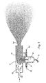
- FIG. 1 is a schematic elevation view of an exemplary water mist generator for fire suppression showing the ultrasonic device generated nanometer-size water mist system of the present invention.
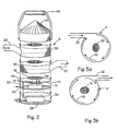
- FIG. 2 is a schematic elevation view of a fire suppression device using an electronic ultrasonic device to generate a nanometer-size water mist.
- FIG.3 is a schematic of top view of flow velocity vectors at the fan or gas ingress and mist egress planes.
- Referring to the figures, the present invention is shown in alternative embodiments. In particular the figures illustrate two embodiments of a device having a
mist generator 8 for producing an ultra fine mist having sub-micron droplets. The embodiments disclose various ways of delivering the mist to a fire consistent with application of the present invention to various fire scenarios. - As shown in figure 1, a
piezoelectric transducer 10 connected to a suitable power source viaconnections 12 is submerged in a bath of water or arranged in physical communication withwater 14. Thepiezoelectric transducer 10 receives an electrical signal and converts electrical oscillations into high frequency mechanical vibrations, which facilitate atomization of fluids by producing ultrasonic pressure or sound waves with rarefaction and compression cycles. The required high frequency pressure waves may be provided by a high frequency wave generating laser device also. Above a certain limit, rarefaction produces cavitations resulting in bubbles that expand during the negative pressure excursion and implode violently during the positive excursion. The cavitations cause the imploding bubbles to surface out as small droplets during compression and form a fog-like mist. Therefore, the ultrasonic waves produced by the high frequency vibration cause atomization of the water into a cloud of droplets. - Above the oscillating disc of the
transducer 10, awater fountain plume 16 is formed with heights varying from a few inches to a foot depending on the oscillator size and frequency. Extremely small droplets ofwater 18 or mist originate and come out of thisfountain 16. Attempts to suppress thisfountain 16 or block the flow results in either the termination or reduction ofmist 18 throughput. As a result, if a fan is used to push the mist out of thegenerator container 8, the air-flow will have the tendency to disturb the fountain flow. Flow behaviors at the entrance into theflow ingress 20 of themist generator 8 and leaving at themist egress 22 should be well organized as shown in figure 3. To optimize the function of the invention, well-organized flow behavior will typically be a feature of the invention discussed further herein. - The
water droplet 18 size produced by the atomization process depends on the surface tension of thewater 14, the density of the water, and the frequency of oscillation of thetransducer 10. Thedroplet 18 diameter decreases with decreasing surface tension of the liquid 14. Thedroplet 18 size also decreases with increasingliquid 14 temperature. Also,droplet 18 diameter decreases with increasing density ofliquid 14 and frequency of oscillation oftransducer 10. In order to produce amist 18 having a significant proportion of droplets having droplet diameters less than one micron as recommended by the invention, the frequency produced by thepiezoelectric transducer 10 herein may be greater than usual. The approximately 1 to 2 MHz frequencies used in prior functions is adequate for producing mists having 1-10 micron particles useful in humidifiers, foggers, cleaning, and other functions. However, frequencies greater than 2.5 MHz may be necessary in certain cases to produce the sub-micron particle mists 18 useful in the fire suppression method taught by the invention, and some modification to present commercial transducers may be required unless other methods are used as suggested above to decrease themist droplet 18 diameter produced. A variable frequency oscillator may be utilized to obtain a broader spectrum ofdroplet 18 size. - As indicated before,
smaller diameter droplets 18 can be produced by decreasing the surface tension of thewater 14, which may be accomplished by adding surfactants or surface-active agents or by some other means. In addition, the temperature of the water14 may be elevated to decrease thedroplet 18 diameter produced. During the process of oscillations and sound wave propagation some heating takes place, which promotes the further reduction ofdroplet 18 size. - The cloud-like collection of extremely
small droplets 18 forming the mist created by the atomizing process hang in the air like a dense gas and slowly succumb to the forces of gravity without any other impetus provided. The impetus provided and, therefore, the mist delivery method used in the invention is an important factor in the effectiveness of themist 18 in fire suppression because themist 18 should be supplied to the firebase. Therefore, the delivery method used by the invention is customized according to the particular fire suppression application, such as open fires, room fires, machinery space, or other scenarios. The delivery of themist 18 may vary with respect to direction, throughput, momentum imparted to themist 18, the composition of carrier gas that may be used, and the mist concentration in the mass flow. Themist generating devices 8 in the figures showrepresentative delivery outlets - The delivery direction of the
mist 18 may be manipulated by the location ofoutlets mist 18. In some fire suppression applications, themist 18 will exit thegenerator 8 and be gravity fed to a fire and self-entrained. While in other applications, themist 18 will need to be transported to a fire by a propellant carrier inert gas, such as nitrogen or carbon dioxide. Or, themist 18 may be transported by air using a fan to push themist 18 toward the firebase and create a suitable flow using the optimum velocity of the diverging air jet. The proportion ofmist 18 to carrier gas or air has to be properly manipulated for sufficient mist ratio to successfully suppress the fire, and the throughput of themist 18 must be sufficient to suppress a fire. - Balancing the momentum of the mist delivery is an important feature of the present method. The mist momentum should be low enough that a fire can self-entrain the
mist 18 as themist 18 is delivered to an area surrounding the application. The injection momentum of themist 18 should be just enough to reach the firebase. If the mist momentum is too high, thecold mist 18 will not be entrained by the fire's buoyancy force and will riot be effective in suppression. If the mist momentum is insufficient, themist 18 may not reach the vicinity of fire and be entrained into the firebase. - A schematic of an embodiment of the
mist generation unit 8 illustrating the invention is shown in figure 2 customized to provide a suitable flow ofmist 18 for some fire suppression applications. A first bottom section of theunit 8 provides apower supply section 26. This section contains a power-utility box 28 including 48 V step-down transformer. Thepower box 28 and transformer is operably connected to atransducer 10 contained within an second section, referred to herein as themist generation section 30. - In the embodiment shown in figure 2, the
transducer 10 is submerged in awater bath 14. Themist generation section 30 may include aningress inlet 32 andegress outlet 34 to provide water to create awater reservoir 14. In some applications, asensor 36 may be provided as shown in thissecond section 30 to monitor the level of thewater reservoir 14, and a system may be provided for controlling theinlet 32 andoutlet 34 of thewater reservoir 14 to adjust the water level accordingly. - A mist egress or
mist outlet section 40 is situated above or near themist generation section 30, and an air or carrier gasflow ingress section 38 is situated above or near themist egress section 40. Alternatively, the relative positions ofmist egress section 40 and gasflow ingress section 38 can be interchanged, namely, themist egress section 40 can be above the gasflow ingress section 38. Themist 18 either flows out of the unit as a result of gravity or may be pushed by a secondary force. A fan may be provided to communicate with themist outlet section 40 via theflow ingress section 38 and direct themist 18 through theegress spout 22 at the desire momentum and proper air to mist mix. Alternatively, a compressed inert gas or compressed air may be arranged to communicate with themist egress section 40 via a conduit of theflow ingress section 38 such as the inlet spout, represented by theingress inlet 20. - Whether a fan or compressed air or any gas is used to direct the
mist 18 to the firebase in the present invention, theflow 42 of carrier medium through themist generator 8 has to be well organized to avoid disturbing thewater fountain 16 extending upward from the water bath orreservoir 14 as discussed above. One way to avoidflow 42 disturbing thefountain 16 is to keep theingress inlet 20 andegress outlet 22 for gas andfluid flow 42 tangential to thecontainer 8 as shown in figure 3. In the embodiment shown, theflow 42 of gas and fluid circulates peripherally of thewater fountain 16, while the center of themist generator 8 where thewater fountain 16 exists is relatively quiet. Assuming thefountain 16 is at the center of thewater bath 14, theflow 42 of gas and fluid will not affect the flow of thewater fountain 16 producing themist 18. Figure 3 shows theflow vectors 42 along the side of thecylindrical container 8 and finally pushing themist 18 out of thecontainer 8 at the selectedoutlet 22 location. - A rectangular geometry does not accommodate well the type of tangential wall-
side flow 42 shown in figure 3. Therefore, thegenerator unit 8 should preferably have a cylindrical geometry as shown in figure 3 rather than rectangular. However, other variations may be beneficial under certain applications with proper care to ensure thewater fountain flow 16 is not disturbed by the flow of mist carrier medium. For instance in figure 1, a water flow is provided in through an inlet 48 andoutlet 50 that communicates with thetransducer 10 to produce themist 18. Themist 18 flows up from thewater fountain 16 and is provide impetus for direction to the firebase by theflow 52 of carrier medium through theflow inlet 54, which is situated above thewater fountain plume 16 so as not to disturb it. - Some existing high-throughput humidifier designs use a fan to directly push the mist upwards out of the container. As a result of direct air current impinging on the water fountain in these high-throughput humidifiers, the mist coming out of the humidifier contains large proportions of coarse water droplets. This mist containing coarse droplets is not efficient for fire suppression application. Moreover, the fan speed of these commercial humidifiers is not calibrated to transport at least 0.8 to 0.9 mass fraction of mist, and the momentum of mist coming out of commercial humidifier units is not controlled to match a specific fire application. Thus, the commercially available high-throughput humidifiers do not possess the mist throughput and delivery strategies discussed herein and would not be well suited or contemplated for use in fire suppression.
- While a preferred embodiment of the invention is disclosed, various alternatives for configuring the device will be found through development within the scope of the present invention. In particular, the locations of the
mist outlet section 40 and carriergas inlet section 38 may be switched. For example, thecarrier gas inlet 38 may be below themist outlet section 40. - The
power supply section 26,mist generation section 30, andmist outlet section 40 of themist generation unit 8 are arranged vertically in figure 2 and provided a top 44 having ahandle 46. Theunit 8 could be arranged having predominately horizontal or vertical construction. An independent portable power source may be added to themist generation unit 8 configuration in desirable applications. For example, a rechargeable battery may be provided for a portablemist generation unit 8, such as a hand-held unit, to be used as indoor or outdoor portable fire extinguishers or like those sometimes used in open room fires. - Adding water-soluble chemical additives to the
water bath 14 may enhance the effectiveness ofwater mist 18 generated by the fire suppression unit. Also, water immiscible liquid additives may be added to thewater bath 14 to enhance fire suppression because the cavitations and atomization process will cause the additives to uniformly mix with thewater mist 18 generated. Some examples include the formation of macro-emulsions or micro-emulsions containing water and other water immiscible fire extinguishing chemical liquids mixed during ultrasonic oscillations. These mechanical micro-emulsions do not need surfactant chemicals to hold the droplets inside the microstructure, which offers the unique advantage of a hybrid micro-emulsion of a chemical suppression liquid and water to be used as a fluid. The resultant hybrid fluid system provides opportunities such as to reduce the effective weight of water to be carried in aircrafts for in-flight fire situations. - There are many fire suppression scenarios in which the present method and apparatus may be used effectively. In lieu of an exhaustive list of applications, several exemplary embodiments and scenarios are presented for consideration without intending to exclude other fire suppression applications in which the invention would be useful. First, the invention may be used in portable hand-held fire extinguishers. In these portable hand-held units, the desired
water mist 18 may be produced at ambient pressure without storing fluids under pressure. Refilling portable unit could be accomplished using a closable opening to receive tap water from a faucet. Further, the portable unit may be battery operated. - In a second embodiment, the invention may be used in computer/electronic data storage rooms and electronically sensitive areas. The ultra fine
sub-micron water mist 18 generated by the invention is especially advantageous to this application because thewater mist 18 will not deposit or accumulate on sensitive electronic equipment. In this embodiment, thewater mist 18 may be produced in a container, such as themist generation unit 8, and themist 18 flowing out of the container could be dispersed using a fan or an induced inert gas flow. In fact, for many computer data center rooms, the raised bottom floor structure therein provides a good opportunity to implement the present mist delivery system. Because the air-ducts in these type data centers are in the floor and the flow of air is always upwards, awater mist 18 using the present system can be easily dispersed from the bottom floor. Optionally, a system based upon the invention designed for this environment may be situated in the ceiling work of a room for selective distribution by gravity to be self-entrained by the fire. - In a third embodiment, the invention may be used in machinery space such as large machinery areas, hangers, turbines, machine shops, or switch rooms. The water mist may be produced by the
mist generation unit 8 and delivered to the fire location by fan or induced inert gas flow. Optionally, mist generators could be installed on a floor below the machine area to be self-entrained by a fire easily from below. - In a fourth embodiment, the invention may be used in ground vehicles, aircraft, ships and submarines. In all of these applications the
mist 18 generated may be re-distributed by fans or induced inert gas flow depending upon space designed for. If the area may be totally flooded with themist 18 and ventilation is secured, then themist 18 may be gravity fed and entrained by the fire flow field. - In a fifth embodiment, the invention may be used to suppress open fires. In this scenario, the
mist 18 is delivered to the firebase by a directed very low velocity jet having a mist concentration of at least 75-80% of the total mass flow. - In a sixth embodiment, the present invention may be used to block the propagation of forest fires. A mist curtain of desired thickness or several meters could be created in the direct path of propagation of the fire. The mist curtain would absorb energy from the leading edge of the fire and slows down the fire. By installing several layers of water mist curtains, the fire propagation rate could be considerably decelerated and finally brought to the complete stop.
- White the invention has been described with respect to certain specific embodiments, it will be appreciated that many modifications and changes may be made by those skilled in the art without departing from the scope of the invention as defined by the claims.
Claims (10)
- A fire suppression method comprising the steps of:a. providing a high frequency pressure wave to a reservoir (14) containing water having a certain surface tension such that the high frequency pressure wave has interaction with the water;b. generating a mist (18) having a proportion of sub-micron diameter droplets from the interaction of the high frequency pressure wave with the water;c. directing the mist (18) toward a base of a fire;d. providing a sufficient momentum to the mist (18) for the fire to self-entrain the mist (18) into the fire;e. providing a sufficient throughput of mist (18) to cool and suppress the fire.
- A fire suppression method according to claim 1, characterized in that the mist (18) flows from a water fountain plume (16) created by the providing of the high frequency pressure wave to the water reservoir (14).
- A fire suppression method according to claim 1, characterized in that the mist (18) is generated at ambient pressure.
- A fire suppression method according to claim 1, characterized in that the mist (18) is introduced to a flow of carrier medium to create a mass of the mist (18) and carrier medium having a sufficient proportion of mist to cool and suppress the fire.
- A fire suppression method according to claim 4, characterized in that the carrier medium is air.
- A fire suppression method according to claim 4, characterized in that the carrier medium includes an inert gas, e.g. nitrogen or carbon dioxide.
- A fire suppression method according to claim 4, characterized in that the flow of the carrier medium is created by propelling the carrier medium by a fan.
- A fire suppression method according to claim 4, characterized in that the flow of the carrier medium is created by propelling the carrier medium by pressure.
- A fire suppression method according to claim 2, characterized in that the mist is introduced to a flow of carrier medium to create a mass of the mist (18) and carrier medium having a sufficient proportion of the mist (18) to cool and suppress the fire and the flow of the carrier medium is tangential to the water fountain plume (16) so as not to significantly disturb the water fountain plume (16).
- A fire suppression method according to claim 1, characterized in that the high frequency pressure wave is generated by converting electronic oscillations to mechanical vibrations, e.g. by a piezoelectric transducer (10).
Applications Claiming Priority (3)
| Application Number | Priority Date | Filing Date | Title |
|---|---|---|---|
| US32339901P | 2001-09-19 | 2001-09-19 | |
| US323399P | 2001-09-19 | ||
| PCT/US2002/029789 WO2003024618A1 (en) | 2001-09-19 | 2002-09-19 | Fire suppression using water mist with ultrafine size droplets |
Publications (3)
| Publication Number | Publication Date |
|---|---|
| EP1441863A1 EP1441863A1 (en) | 2004-08-04 |
| EP1441863A4 EP1441863A4 (en) | 2004-10-13 |
| EP1441863B1 true EP1441863B1 (en) | 2006-12-27 |
Family
ID=23259050
Family Applications (1)
| Application Number | Title | Priority Date | Filing Date |
|---|---|---|---|
| EP02778285A Expired - Lifetime EP1441863B1 (en) | 2001-09-19 | 2002-09-19 | Fire suppression using water mist with ultrafine size droplets |
Country Status (7)
| Country | Link |
|---|---|
| US (2) | US7090028B2 (en) |
| EP (1) | EP1441863B1 (en) |
| JP (1) | JP2005502434A (en) |
| AT (1) | ATE349285T1 (en) |
| DE (1) | DE60217154T2 (en) |
| ES (1) | ES2279891T3 (en) |
| WO (1) | WO2003024618A1 (en) |
Families Citing this family (54)
| Publication number | Priority date | Publication date | Assignee | Title |
|---|---|---|---|---|
| US20070193753A1 (en) * | 2006-02-21 | 2007-08-23 | Adiga Kayyani C | A method and device for suppression of fire by local flooding with ultra-fine water mist |
| US7195179B2 (en) * | 2003-06-01 | 2007-03-27 | Piezo Technologies | Piezoelectric mist generation device |
| DE102004024615B4 (en) * | 2004-05-18 | 2008-08-28 | Airbus Deutschland Gmbh | Device for humidifying the air in a cabin of a passenger or cargo aircraft |
| ATE460196T1 (en) | 2005-09-26 | 2010-03-15 | Univ Leeds | MEDICINAL DISTRIBUTION |
| EP2205327B1 (en) * | 2007-10-29 | 2012-09-05 | Kidde IP Holdings Limited | Fire suppression system with freeze protection |
| WO2009114782A2 (en) * | 2008-03-13 | 2009-09-17 | Vornado Air Llc | Ultrasonic humidifier |
| EP2153872A1 (en) | 2008-07-23 | 2010-02-17 | Total Petrochemicals Research Feluy | Method to mitigate the consequences of an unconfined or partially confined vapor cloud explosion |
| US20100032175A1 (en) * | 2008-08-07 | 2010-02-11 | Boyd Joseph J | Bubble Fire Extinguisher |
| WO2010051107A1 (en) * | 2008-09-11 | 2010-05-06 | Integrated Systems Excellence Corporation | Fire suppression systems and methods |
| US8915307B2 (en) | 2008-12-18 | 2014-12-23 | Utc Fire & Security Corporation | Atomizing nozzle for a fire suppression system |
| US20100252284A1 (en) * | 2009-04-03 | 2010-10-07 | Kodiac Investment, Llc | Apparatus And Method For Combating Fires |
| US8077317B2 (en) * | 2009-04-09 | 2011-12-13 | Kidde Technologies, Inc. | Sensor head for a dry powder agent |
| US8161790B2 (en) * | 2009-04-09 | 2012-04-24 | Kidde Technologies, Inc. | Measurement system for powder based agents |
| US8004684B2 (en) * | 2009-04-09 | 2011-08-23 | Kidde Technologies, Inc. | Sensor head for a dry powder agent |
| CN102458627B (en) * | 2009-06-22 | 2016-04-06 | 松下知识产权经营株式会社 | Use the mist of elastic surface wave and the production method of micro-bubble or micro-bubble and mist and micro-bubble or micro-bubble generation device |
| US20110256823A1 (en) * | 2009-12-02 | 2011-10-20 | International Business Machines Corporation | Data center ceiling |
| US8118973B2 (en) * | 2010-02-17 | 2012-02-21 | Johns Manville | Method of applying de-dusting agents to fibrous products and products |
| US8632244B2 (en) * | 2010-03-09 | 2014-01-21 | California Institute Of Technology | In-service monitoring of steam pipe systems at high temperatures |
| WO2012100784A1 (en) | 2011-01-27 | 2012-08-02 | Engineering For Industry | Low pressure water mist nozzle (hs 10) |
| US9207172B2 (en) | 2011-05-26 | 2015-12-08 | Kidde Technologies, Inc. | Velocity survey with powderizer and agent flow indicator |
| CN102961841B (en) * | 2012-12-05 | 2016-03-09 | 中山大学 | A kind of superfine spray total flooding extinguishing device and method |
| TWM475144U (en) * | 2013-11-08 | 2014-04-01 | Chunghwa Picture Tubes Ltd | Multifunctional growing system |
| US20150300926A1 (en) * | 2014-04-16 | 2015-10-22 | Institute Of Labor, Occupational Safety And Health | Wet-film particle impactor |
| US9668434B2 (en) * | 2014-07-23 | 2017-06-06 | Aessense Technology Hong Kong Ltd. | Root misting system |
| US10569115B2 (en) | 2014-11-24 | 2020-02-25 | Force Sv, Llc | Methods and systems for disrupting phenomena with waves |
| US9821180B2 (en) | 2016-04-08 | 2017-11-21 | Kenneth Wendlin Heck | Fire suppressant systems |
| CN106761887B (en) * | 2016-11-18 | 2018-11-16 | 济宁学院 | A kind of coal mine gob extinguishing device |
| FR3070908B1 (en) * | 2017-09-11 | 2020-07-24 | Valeo Systemes Thermiques | MOTOR VEHICLE NEBULIZATION SYSTEM |
| US11306929B2 (en) | 2018-09-09 | 2022-04-19 | Vornado Air, Llc | Portable steam humidifier |
| US11549699B2 (en) | 2017-10-03 | 2023-01-10 | Vornado Air, Llc | Portable humidifier |
| CN107782480B (en) * | 2017-11-17 | 2023-08-29 | 北京石油化工学院 | Method and device for testing minimum ignition energy of combustible dust/combustible gas mixture |
| US10311444B1 (en) | 2017-12-02 | 2019-06-04 | M-Fire Suppression, Inc. | Method of providing class-A fire-protection to wood-framed buildings using on-site spraying of clean fire inhibiting chemical liquid on exposed interior wood surfaces of the wood-framed buildings, and mobile computing systems for uploading fire-protection certifications and status information to a central database and remote access thereof by firefighters on job site locations during fire outbreaks on construction sites |
| US10695597B2 (en) | 2017-12-02 | 2020-06-30 | M-Fire Holdings Llc | Method of and apparatus for applying fire and smoke inhibiting compositions on ground surfaces before the incidence of wild-fires, and also thereafter, upon smoldering ambers and ashes to reduce smoke and suppress fire re-ignition |
| US10290004B1 (en) | 2017-12-02 | 2019-05-14 | M-Fire Suppression, Inc. | Supply chain management system for supplying clean fire inhibiting chemical (CFIC) totes to a network of wood-treating lumber and prefabrication panel factories and wood-framed building construction job sites |
| US10814150B2 (en) | 2017-12-02 | 2020-10-27 | M-Fire Holdings Llc | Methods of and system networks for wireless management of GPS-tracked spraying systems deployed to spray property and ground surfaces with environmentally-clean wildfire inhibitor to protect and defend against wildfires |
| US10653904B2 (en) | 2017-12-02 | 2020-05-19 | M-Fire Holdings, Llc | Methods of suppressing wild fires raging across regions of land in the direction of prevailing winds by forming anti-fire (AF) chemical fire-breaking systems using environmentally clean anti-fire (AF) liquid spray applied using GPS-tracking techniques |
| US10430757B2 (en) | 2017-12-02 | 2019-10-01 | N-Fire Suppression, Inc. | Mass timber building factory system for producing prefabricated class-A fire-protected mass timber building components for use in constructing prefabricated class-A fire-protected mass timber buildings |
| US11395931B2 (en) | 2017-12-02 | 2022-07-26 | Mighty Fire Breaker Llc | Method of and system network for managing the application of fire and smoke inhibiting compositions on ground surfaces before the incidence of wild-fires, and also thereafter, upon smoldering ambers and ashes to reduce smoke and suppress fire re-ignition |
| US10260232B1 (en) | 2017-12-02 | 2019-04-16 | M-Fire Supression, Inc. | Methods of designing and constructing Class-A fire-protected multi-story wood-framed buildings |
| US10332222B1 (en) | 2017-12-02 | 2019-06-25 | M-Fire Supression, Inc. | Just-in-time factory methods, system and network for prefabricating class-A fire-protected wood-framed buildings and components used to construct the same |
| US11836807B2 (en) | 2017-12-02 | 2023-12-05 | Mighty Fire Breaker Llc | System, network and methods for estimating and recording quantities of carbon securely stored in class-A fire-protected wood-framed and mass-timber buildings on construction job-sites, and class-A fire-protected wood-framed and mass timber components in factory environments |
| US11865390B2 (en) | 2017-12-03 | 2024-01-09 | Mighty Fire Breaker Llc | Environmentally-clean water-based fire inhibiting biochemical compositions, and methods of and apparatus for applying the same to protect property against wildfire |
| US11865394B2 (en) | 2017-12-03 | 2024-01-09 | Mighty Fire Breaker Llc | Environmentally-clean biodegradable water-based concentrates for producing fire inhibiting and fire extinguishing liquids for fighting class A and class B fires |
| US20190232094A1 (en) * | 2018-01-04 | 2019-08-01 | Nanomist Fire Safety, Llc | Method and Device for Fire Protection by a Hybrid Composition of Mist and Inert Gas |
| US11826592B2 (en) | 2018-01-09 | 2023-11-28 | Mighty Fire Breaker Llc | Process of forming strategic chemical-type wildfire breaks on ground surfaces to proactively prevent fire ignition and flame spread, and reduce the production of smoke in the presence of a wild fire |
| KR102465883B1 (en) * | 2020-02-07 | 2022-11-10 | 공주대학교 산학협력단 | fluid spray apparatus for fire fighting |
| DE102020201732A1 (en) * | 2020-02-12 | 2021-08-12 | Thyssenkrupp Ag | Method for minimizing detonation damage on a watercraft |
| CN111250332B (en) * | 2020-03-20 | 2022-12-27 | 乐比(广州)健康产业有限公司 | Ultrasonic atomizer |
| US20210308506A1 (en) | 2020-04-06 | 2021-10-07 | Jeff Johnson | Wide-Area Fire-Retardant System Using Distributed Dense Water Fogger |
| US11268891B2 (en) | 2020-06-17 | 2022-03-08 | Kidde Technologies, Inc. | Fire extinguishing agent concentration measuring system and method |
| US11280731B2 (en) | 2020-06-24 | 2022-03-22 | Kidde Technologies, Inc. | Fire extinguishing agent concentration measuring system and method of measuring a fire extinguishing agent within an environment |
| US11911643B2 (en) | 2021-02-04 | 2024-02-27 | Mighty Fire Breaker Llc | Environmentally-clean fire inhibiting and extinguishing compositions and products for sorbing flammable liquids while inhibiting ignition and extinguishing fire |
| CN115645799A (en) * | 2022-09-07 | 2023-01-31 | 北京航空航天大学 | Fine liquid mist fire extinguishing apparatus and method of operating the same |
| CN116306364B (en) * | 2023-03-13 | 2024-03-22 | 武汉理工大学 | Wave-absorbing simulation method for explosion water mist in cabin |
Family Cites Families (13)
| Publication number | Priority date | Publication date | Assignee | Title |
|---|---|---|---|---|
| US3584412A (en) * | 1967-11-30 | 1971-06-15 | Boeing Co | Stable mist generation method and apparatus, the products and uses thereof |
| GB1554577A (en) * | 1976-11-22 | 1979-10-24 | Heath R C | Fire extinguishers |
| US4378851A (en) | 1980-09-08 | 1983-04-05 | Quad Environmental Technologies Corporation | Method for inhibiting explosions |
| US5088560A (en) * | 1990-11-01 | 1992-02-18 | Systron Donner Corporation | Zero force fire extinguisher |
| JPH0771653B2 (en) | 1990-12-28 | 1995-08-02 | ティーディーケイ株式会社 | Ultrasonic liquid atomizer |
| EP0514610B1 (en) | 1991-05-23 | 1996-04-24 | Zeus | Method and apparatus for area fire protection |
| DE69206824C5 (en) * | 1991-12-04 | 2009-07-09 | The Technology Partnership PLC, Melbourn, Royston | DEVICE AND METHOD FOR PRODUCING FLUID FLUIDS |
| US5541627A (en) * | 1991-12-17 | 1996-07-30 | Xerox Corporation | Method and apparatus for ejecting a droplet using an electric field |
| US5495893A (en) | 1994-05-10 | 1996-03-05 | Ada Technologies, Inc. | Apparatus and method to control deflagration of gases |
| DE19500477C1 (en) * | 1994-08-08 | 1995-11-23 | Amrona Ag | Fire extinguisher with container esp. for forest fires |
| DE19643929C2 (en) * | 1996-10-30 | 1998-08-06 | Wagner Alarm Sicherung | Device and method for extinguishing fires |
| US6390203B1 (en) * | 1999-01-11 | 2002-05-21 | Yulian Y. Borisov | Fire suppression apparatus and method |
| JP4130630B2 (en) * | 2001-09-19 | 2008-08-06 | シー.アディガ カイヤーニ | Method and apparatus for producing, extracting and delivering mist with ultrafine droplets |
-
2002
- 2002-09-19 WO PCT/US2002/029789 patent/WO2003024618A1/en active IP Right Grant
- 2002-09-19 AT AT02778285T patent/ATE349285T1/en not_active IP Right Cessation
- 2002-09-19 ES ES02778285T patent/ES2279891T3/en not_active Expired - Lifetime
- 2002-09-19 EP EP02778285A patent/EP1441863B1/en not_active Expired - Lifetime
- 2002-09-19 DE DE60217154T patent/DE60217154T2/en not_active Expired - Lifetime
- 2002-09-19 US US10/247,147 patent/US7090028B2/en not_active Expired - Lifetime
- 2002-09-19 JP JP2003528307A patent/JP2005502434A/en active Pending
-
2005
- 2005-12-20 US US11/306,244 patent/US20060196681A1/en not_active Abandoned
Also Published As
| Publication number | Publication date |
|---|---|
| EP1441863A4 (en) | 2004-10-13 |
| EP1441863A1 (en) | 2004-08-04 |
| DE60217154T2 (en) | 2007-10-18 |
| DE60217154D1 (en) | 2007-02-08 |
| US7090028B2 (en) | 2006-08-15 |
| JP2005502434A (en) | 2005-01-27 |
| ATE349285T1 (en) | 2007-01-15 |
| ES2279891T3 (en) | 2007-09-01 |
| WO2003024618A1 (en) | 2003-03-27 |
| US20030051886A1 (en) | 2003-03-20 |
| US20060196681A1 (en) | 2006-09-07 |
Similar Documents
| Publication | Publication Date | Title |
|---|---|---|
| EP1441863B1 (en) | Fire suppression using water mist with ultrafine size droplets | |
| JP2005502434A5 (en) | ||
| US9010663B2 (en) | Method and apparatus for generating a mist | |
| US9004375B2 (en) | Method and apparatus for generating a mist | |
| CA2611961C (en) | High velocity low pressure emitter | |
| US10507480B2 (en) | Method and apparatus for generating a mist | |
| JP5323122B2 (en) | Double fire extinguishing fire suppression system using high-speed and low-pressure emitters | |
| Jian-yong et al. | Progress in research and application of electronic ultrasonic water mist fire suppression technology | |
| EP4062979A1 (en) | Fire extinguishing apparatus | |
| CN202942576U (en) | Ultrafine water mist total-flooding fire extinguisher |
Legal Events
| Date | Code | Title | Description |
|---|---|---|---|
| PUAI | Public reference made under article 153(3) epc to a published international application that has entered the european phase |
Free format text: ORIGINAL CODE: 0009012 |
|
| 17P | Request for examination filed |
Effective date: 20040419 |
|
| AK | Designated contracting states |
Kind code of ref document: A1 Designated state(s): AT BE BG CH CY CZ DE DK EE ES FI FR GB GR IE IT LI LU MC NL PT SE SK TR |
|
| AX | Request for extension of the european patent |
Extension state: AL LT LV MK RO SI |
|
| A4 | Supplementary search report drawn up and despatched |
Effective date: 20040830 |
|
| RIC1 | Information provided on ipc code assigned before grant |
Ipc: 7A 61M 11/02 B Ipc: 7A 61M 11/06 B Ipc: 7B 05D 1/08 A Ipc: 7A 62C 5/00 B Ipc: 7A 62C 39/00 B Ipc: 7A 62C 13/62 B Ipc: 7A 62C 31/00 B Ipc: 7B 05D 3/04 B |
|
| GRAP | Despatch of communication of intention to grant a patent |
Free format text: ORIGINAL CODE: EPIDOSNIGR1 |
|
| GRAS | Grant fee paid |
Free format text: ORIGINAL CODE: EPIDOSNIGR3 |
|
| GRAA | (expected) grant |
Free format text: ORIGINAL CODE: 0009210 |
|
| AK | Designated contracting states |
Kind code of ref document: B1 Designated state(s): AT BE BG CH CY CZ DE DK EE ES FI FR GB GR IE IT LI LU MC NL PT SE SK TR |
|
| PG25 | Lapsed in a contracting state [announced via postgrant information from national office to epo] |
Ref country code: BE Free format text: LAPSE BECAUSE OF FAILURE TO SUBMIT A TRANSLATION OF THE DESCRIPTION OR TO PAY THE FEE WITHIN THE PRESCRIBED TIME-LIMIT Effective date: 20061227 Ref country code: IT Free format text: LAPSE BECAUSE OF FAILURE TO SUBMIT A TRANSLATION OF THE DESCRIPTION OR TO PAY THE FEE WITHIN THE PRESCRIBED TIME-LIMIT;WARNING: LAPSES OF ITALIAN PATENTS WITH EFFECTIVE DATE BEFORE 2007 MAY HAVE OCCURRED AT ANY TIME BEFORE 2007. THE CORRECT EFFECTIVE DATE MAY BE DIFFERENT FROM THE ONE RECORDED. Effective date: 20061227 Ref country code: NL Free format text: LAPSE BECAUSE OF FAILURE TO SUBMIT A TRANSLATION OF THE DESCRIPTION OR TO PAY THE FEE WITHIN THE PRESCRIBED TIME-LIMIT Effective date: 20061227 Ref country code: SK Free format text: LAPSE BECAUSE OF FAILURE TO SUBMIT A TRANSLATION OF THE DESCRIPTION OR TO PAY THE FEE WITHIN THE PRESCRIBED TIME-LIMIT Effective date: 20061227 Ref country code: FI Free format text: LAPSE BECAUSE OF FAILURE TO SUBMIT A TRANSLATION OF THE DESCRIPTION OR TO PAY THE FEE WITHIN THE PRESCRIBED TIME-LIMIT Effective date: 20061227 Ref country code: LI Free format text: LAPSE BECAUSE OF FAILURE TO SUBMIT A TRANSLATION OF THE DESCRIPTION OR TO PAY THE FEE WITHIN THE PRESCRIBED TIME-LIMIT Effective date: 20061227 Ref country code: CH Free format text: LAPSE BECAUSE OF FAILURE TO SUBMIT A TRANSLATION OF THE DESCRIPTION OR TO PAY THE FEE WITHIN THE PRESCRIBED TIME-LIMIT Effective date: 20061227 Ref country code: DK Free format text: LAPSE BECAUSE OF FAILURE TO SUBMIT A TRANSLATION OF THE DESCRIPTION OR TO PAY THE FEE WITHIN THE PRESCRIBED TIME-LIMIT Effective date: 20061227 Ref country code: AT Free format text: LAPSE BECAUSE OF FAILURE TO SUBMIT A TRANSLATION OF THE DESCRIPTION OR TO PAY THE FEE WITHIN THE PRESCRIBED TIME-LIMIT Effective date: 20061227 Ref country code: CZ Free format text: LAPSE BECAUSE OF FAILURE TO SUBMIT A TRANSLATION OF THE DESCRIPTION OR TO PAY THE FEE WITHIN THE PRESCRIBED TIME-LIMIT Effective date: 20061227 |
|
| REG | Reference to a national code |
Ref country code: GB Ref legal event code: FG4D |
|
| REG | Reference to a national code |
Ref country code: IE Ref legal event code: FG4D |
|
| REF | Corresponds to: |
Ref document number: 60217154 Country of ref document: DE Date of ref document: 20070208 Kind code of ref document: P |
|
| PG25 | Lapsed in a contracting state [announced via postgrant information from national office to epo] |
Ref country code: BG Free format text: LAPSE BECAUSE OF FAILURE TO SUBMIT A TRANSLATION OF THE DESCRIPTION OR TO PAY THE FEE WITHIN THE PRESCRIBED TIME-LIMIT Effective date: 20070327 Ref country code: SE Free format text: LAPSE BECAUSE OF FAILURE TO SUBMIT A TRANSLATION OF THE DESCRIPTION OR TO PAY THE FEE WITHIN THE PRESCRIBED TIME-LIMIT Effective date: 20070327 |
|
| PG25 | Lapsed in a contracting state [announced via postgrant information from national office to epo] |
Ref country code: PT Free format text: LAPSE BECAUSE OF FAILURE TO SUBMIT A TRANSLATION OF THE DESCRIPTION OR TO PAY THE FEE WITHIN THE PRESCRIBED TIME-LIMIT Effective date: 20070528 |
|
| NLV1 | Nl: lapsed or annulled due to failure to fulfill the requirements of art. 29p and 29m of the patents act | ||
| REG | Reference to a national code |
Ref country code: CH Ref legal event code: PL |
|
| ET | Fr: translation filed | ||
| REG | Reference to a national code |
Ref country code: ES Ref legal event code: FG2A Ref document number: 2279891 Country of ref document: ES Kind code of ref document: T3 |
|
| PLBE | No opposition filed within time limit |
Free format text: ORIGINAL CODE: 0009261 |
|
| STAA | Information on the status of an ep patent application or granted ep patent |
Free format text: STATUS: NO OPPOSITION FILED WITHIN TIME LIMIT |
|
| 26N | No opposition filed |
Effective date: 20070928 |
|
| PG25 | Lapsed in a contracting state [announced via postgrant information from national office to epo] |
Ref country code: GR Free format text: LAPSE BECAUSE OF FAILURE TO SUBMIT A TRANSLATION OF THE DESCRIPTION OR TO PAY THE FEE WITHIN THE PRESCRIBED TIME-LIMIT Effective date: 20070328 Ref country code: MC Free format text: LAPSE BECAUSE OF NON-PAYMENT OF DUE FEES Effective date: 20070930 |
|
| PG25 | Lapsed in a contracting state [announced via postgrant information from national office to epo] |
Ref country code: IE Free format text: LAPSE BECAUSE OF NON-PAYMENT OF DUE FEES Effective date: 20070919 |
|
| PG25 | Lapsed in a contracting state [announced via postgrant information from national office to epo] |
Ref country code: EE Free format text: LAPSE BECAUSE OF FAILURE TO SUBMIT A TRANSLATION OF THE DESCRIPTION OR TO PAY THE FEE WITHIN THE PRESCRIBED TIME-LIMIT Effective date: 20061227 |
|
| PG25 | Lapsed in a contracting state [announced via postgrant information from national office to epo] |
Ref country code: CY Free format text: LAPSE BECAUSE OF FAILURE TO SUBMIT A TRANSLATION OF THE DESCRIPTION OR TO PAY THE FEE WITHIN THE PRESCRIBED TIME-LIMIT Effective date: 20061227 Ref country code: LU Free format text: LAPSE BECAUSE OF NON-PAYMENT OF DUE FEES Effective date: 20070919 |
|
| PG25 | Lapsed in a contracting state [announced via postgrant information from national office to epo] |
Ref country code: TR Free format text: LAPSE BECAUSE OF FAILURE TO SUBMIT A TRANSLATION OF THE DESCRIPTION OR TO PAY THE FEE WITHIN THE PRESCRIBED TIME-LIMIT Effective date: 20061227 |
|
| REG | Reference to a national code |
Ref country code: FR Ref legal event code: PLFP Year of fee payment: 15 |
|
| REG | Reference to a national code |
Ref country code: FR Ref legal event code: PLFP Year of fee payment: 16 |
|
| REG | Reference to a national code |
Ref country code: FR Ref legal event code: PLFP Year of fee payment: 17 |
|
| PGFP | Annual fee paid to national office [announced via postgrant information from national office to epo] |
Ref country code: FR Payment date: 20210831 Year of fee payment: 20 |
|
| PGFP | Annual fee paid to national office [announced via postgrant information from national office to epo] |
Ref country code: GB Payment date: 20210831 Year of fee payment: 20 Ref country code: DE Payment date: 20210812 Year of fee payment: 20 |
|
| PGFP | Annual fee paid to national office [announced via postgrant information from national office to epo] |
Ref country code: ES Payment date: 20211007 Year of fee payment: 20 |
|
| REG | Reference to a national code |
Ref country code: DE Ref legal event code: R071 Ref document number: 60217154 Country of ref document: DE |
|
| REG | Reference to a national code |
Ref country code: ES Ref legal event code: FD2A Effective date: 20220926 |
|
| REG | Reference to a national code |
Ref country code: GB Ref legal event code: PE20 Expiry date: 20220918 |
|
| PG25 | Lapsed in a contracting state [announced via postgrant information from national office to epo] |
Ref country code: GB Free format text: LAPSE BECAUSE OF EXPIRATION OF PROTECTION Effective date: 20220918 Ref country code: ES Free format text: LAPSE BECAUSE OF EXPIRATION OF PROTECTION Effective date: 20220920 |