EP1441567A2 - Electric oven - Google Patents
Electric oven Download PDFInfo
- Publication number
- EP1441567A2 EP1441567A2 EP03010352A EP03010352A EP1441567A2 EP 1441567 A2 EP1441567 A2 EP 1441567A2 EP 03010352 A EP03010352 A EP 03010352A EP 03010352 A EP03010352 A EP 03010352A EP 1441567 A2 EP1441567 A2 EP 1441567A2
- Authority
- EP
- European Patent Office
- Prior art keywords
- cavity
- electric oven
- heat
- heating
- heating unit
- Prior art date
- Legal status (The legal status is an assumption and is not a legal conclusion. Google has not performed a legal analysis and makes no representation as to the accuracy of the status listed.)
- Granted
Links
Images


Classifications
-
- F—MECHANICAL ENGINEERING; LIGHTING; HEATING; WEAPONS; BLASTING
- F24—HEATING; RANGES; VENTILATING
- F24C—DOMESTIC STOVES OR RANGES ; DETAILS OF DOMESTIC STOVES OR RANGES, OF GENERAL APPLICATION
- F24C7/00—Stoves or ranges heated by electric energy
-
- H—ELECTRICITY
- H05—ELECTRIC TECHNIQUES NOT OTHERWISE PROVIDED FOR
- H05B—ELECTRIC HEATING; ELECTRIC LIGHT SOURCES NOT OTHERWISE PROVIDED FOR; CIRCUIT ARRANGEMENTS FOR ELECTRIC LIGHT SOURCES, IN GENERAL
- H05B6/00—Heating by electric, magnetic or electromagnetic fields
- H05B6/64—Heating using microwaves
- H05B6/647—Aspects related to microwave heating combined with other heating techniques
- H05B6/6488—Aspects related to microwave heating combined with other heating techniques combined with induction heating
-
- H—ELECTRICITY
- H05—ELECTRIC TECHNIQUES NOT OTHERWISE PROVIDED FOR
- H05B—ELECTRIC HEATING; ELECTRIC LIGHT SOURCES NOT OTHERWISE PROVIDED FOR; CIRCUIT ARRANGEMENTS FOR ELECTRIC LIGHT SOURCES, IN GENERAL
- H05B6/00—Heating by electric, magnetic or electromagnetic fields
- H05B6/02—Induction heating
- H05B6/10—Induction heating apparatus, other than furnaces, for specific applications
- H05B6/12—Cooking devices
- H05B6/129—Cooking devices induction ovens
-
- H—ELECTRICITY
- H05—ELECTRIC TECHNIQUES NOT OTHERWISE PROVIDED FOR
- H05B—ELECTRIC HEATING; ELECTRIC LIGHT SOURCES NOT OTHERWISE PROVIDED FOR; CIRCUIT ARRANGEMENTS FOR ELECTRIC LIGHT SOURCES, IN GENERAL
- H05B6/00—Heating by electric, magnetic or electromagnetic fields
- H05B6/64—Heating using microwaves
- H05B6/647—Aspects related to microwave heating combined with other heating techniques
- H05B6/6473—Aspects related to microwave heating combined with other heating techniques combined with convection heating
-
- H—ELECTRICITY
- H05—ELECTRIC TECHNIQUES NOT OTHERWISE PROVIDED FOR
- H05B—ELECTRIC HEATING; ELECTRIC LIGHT SOURCES NOT OTHERWISE PROVIDED FOR; CIRCUIT ARRANGEMENTS FOR ELECTRIC LIGHT SOURCES, IN GENERAL
- H05B6/00—Heating by electric, magnetic or electromagnetic fields
- H05B6/64—Heating using microwaves
- H05B6/647—Aspects related to microwave heating combined with other heating techniques
- H05B6/6482—Aspects related to microwave heating combined with other heating techniques combined with radiant heating, e.g. infrared heating
Definitions
- the present invention relates to an electric oven, and more particularly, to an electric oven which increases temperature fast and reduces heat loss in accordance with that a cavity surface generates its own heat by using an induction heating.
- an electric oven is a cook used in the kitchen having its own heating means.
- the electric oven usually cooks food in a cooking chamber by using heat of an electric heater as a heating source, but sometimes uses microwave as a subsidiary heating source by mounting a magnetron.
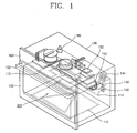
- FIG. 1 is a schematic perspective view showing a construction of an electric oven in accordance with the conventional art, in which a heater is mounted as a main heating source, and microwave is used as another heating source.
- the conventional electric oven has a case 100 composed of a plurality of plates, which constitutes an appearance.
- the electric oven can be composed of a plate for forming a lower surface thereof and cabinets for forming both sides and an upper surface thereof.
- a cavity 200 into which food is put and cooking is performed is formed in the case 100.
- the cavity 200 is selectively opened and closed by a door 130.
- a lower end of the door 130 is hinge-coupled to a front surface of the cavity 200, and a door handle 132 is formed at an upper end of the door 130. Accordingly, when the door handle 132 is pulled, the upper end is rotated downwardly on the basis of the lower end, thereby opening and closing the cavity 200.
- a managing unit 160 is provided at an upper end of the electric oven which is not shielded by the door 130. Generally, each kind of button required to manage the electric oven, and a display window for displaying an operation state of the electric oven can be formed at the managing unit 160.
- a lower heater 112 is installed at a lower side of the cavity 200.
- the lower heater 112 generally uses a sheath heater.
- the lower heater 112 transmits heat to the cavity 200 through an inner bottom of the cavity 200.
- An upper heater 110 is installed at an upper side of the cavity 200, which also uses the sheath heater, generally.
- the sheath heater is composed of a metal pipe at an outer portion, a heat line located in the metal pipe, and an insulating material installed between the metal pipe and the heat line.
- the sheath heater is well know, thereby omitting its detail explanation.
- a convection heater 114 is installed at a back side of the cavity 200.
- a convection fan 140 is installed at the rear side of the cavity 200 where the convection heater 114 is installed.
- the convection fan 140 supplies air heated by the convection heater 114 to the cavity 200.
- a plurality of through holes 142 are formed at the back side of the cavity 200 corresponding to the convection heater 114.
- a magnetron 150 for supplying heat to the cavity 200 as another heating source is formed at a space between an upper portion of the cavity 200 and the case 100.
- the magnetron 150 oscillates microwave and supplies heat to the cavity 200.
- the magnetron 150 supplies the microwave into a wave guide 152 mounted at the upper surface of the cavity 200.
- a reference numeral 144 denotes a cooling fan for cooling components including the magnetron 150. Other components for supplying the microwave will not be explained.
- a reference numeral 180 denotes an oven lamp for lightening inside of a cooking chamber.
- Food is put on the cavity 200,the door 130 is closed, and a power source is supplied in a state that the cooking chamber is shielded from outside, thereby performing cooking. That is, when the power source is supplied, heat from the lower heater 112 is conducted to the bottom of the cavity 200. The conducted heat heats air in the cavity 200, and the heated air is transmitted to the food. Also, the upper heater 110 transmits heat to the food by radiation and convection, and the heat supplied from the convection heater 114 is transmitted to the cooking chamber as hot blast through the plurality of holes 142 by the convection fan 140 and transmitted to the food.
- the microwave oscillated from the magnetron 150 can be used to cook the food by the user's selection.
- the electric oven has to be heated in advance as a predetermined temperature before cooking. Also, in order to use an automatic cleaning function using pyrolysis in the cavity 200, an inner temperature of the electric oven has to be increased more than 500°C and then considerable time has to lapse to combust oil of an inner wall.
- the lower heater 112 and the upper heater 110 use the sheath heater.
- the sheath heater takes much time in increasing temperature up to a saturation temperature since specific heat is great.
- contact heat resistance is great.
- heat efficiency is degraded by depending on natural convection having a low transmittance efficiency and the radiation which requires great temperature difference with the lower surface of the lower heater 112.
- an object of the present invention is to provide an electric oven which can transmit heat of heat source to a cavity faster by applying an induction heating at both sides of the cavity.
- preheating time or cooking time can be minimized, inner temperature of the entire cavity can be uniform, and cleaning for inside of the cavity using pyrolysis can be performed faster and more uniformly.
- an electric oven comprising: a case having a door at a front side and having a cavity for receiving food therein; a magnetron installed at one side of an upper portion of the cavity for generating microwave of high frequency and supplying heat to the cavity; an inverter for generating high frequency at a space between the case and the cavity; a first heating unit installed right and left sides of the cavity for supplying heat to the cavity from the right and left sides; a second heating unit installed at an upper side of the cavity for supplying heat to the cavity from the upper side; a third heating unit installed at a lower side of the cavity for supplying heat to the cavity from the lower side; and a fourth heating unit installed at a back side of the cavity for supplying heat to the cavity from the back side.
- Figure 2 is a schematic perspective view showing a construction of an electric oven according to one embodiment of the present invention
- Figure 3 is a longitudinal section view showing a position of a heating unit of Figure 2
- Figure 4 is a longitudinal section view showing a position of the heating unit of Figure 2 according to another embodiment.
- an electric oven according to the present invention has a case 10 composed of a plurality of plates, which constitutes an appearance.
- the electric oven can be composed of a plate for forming a lower surface thereof and cabinets for forming both sides and an upper surface thereof.
- a cavity 20 into which food is put and cooking is performed is formed in the case 10.
- the cavity 20 is formed of a metal having a high thermal conductivity in order to generate heat through an induction heating at both sides thereof.
- the cavity 20 is selectively opened and closed by a door 30.
- a lower end of the door 30 is hinge-coupled to a front surface of the cavity 20, and a door handle 32 is formed at an upper end of the door 30. Accordingly, when the door handle 32 is pulled, the upper end is rotated downwardly on the basis of the lower end, thereby opening and closing the cavity 20.
- a managing unit 60 is provided at an upper end of the electric oven which is not shielded by the door 30. Generally, each kind of button required to manage the electric oven, and a display window for displaying an operation state of the electric oven can be formed at the managing unit 60.
- the electric oven according to the present invention is provided with heating units at every outside of the cavity 20 except a surface where the door is formed.
- First heating units 13a and 13b are installed at right and left sides of the cavity 20.
- the first heating units 13a and 13b are provided with induction coil for induction heating.
- the induction heating is performed by partially heating a metal having a high thermal conduction, or by using high frequency when only surfaces of a metal are to be heated.
- both sides of the cavity 20 are formed with a metal having a thermal conduction.
- a second heating unit 11 is installed at an upper side of the cavity 20, in which a sheath heater is mainly used like in the conventional art.
- a third heating unit 12 is installed at a lower side of the cavity 20.
- the third heating unit can use the sheath heater like in the conventional art, or can use induction coil for induction heating.
- the third heating unit 12 supplies heat to the cavity 20 through an inner bottom of the cavity 20.
- a fourth heating unit 14 is installed at a back side of the cavity 20.
- a convection heater is used.
- a convection fan 40 is installed at the back side of the cavity 20 where the convection heater is installed. The convection fan 40 supplies air heated by the convection heater to the cavity 20.
- a plurality of through holes 42 are formed at the back side of the cavity 20 corresponding to the convection heater.
- a magnetron 50 for supplying heat to the cavity 20 as another heating source is formed at a space between the upper portion of the cavity 20 and the case 10.
- the magnetron 50 oscillates microwave having high frequency and supplies heat to the cavity 20.
- the magnetron 50 supplies the microwave into a wave guide 52 mounted at the upper surface of the cavity 20.
- an inverter 56 for generating high frequency of 20 ⁇ 40 kHz is installed at a space between the upper surface of the cavity 20 and a corresponding surface.
- a circuit of the inverter 56 can be shared together with a circuit of the magnetron.
- FIG 4 shows that the first heating unit 13a and 13b, the second heating unit 11, and the third heating unit 12 are constructed with only the sheath heater. At this time, too, the fourth heating unit 14 is constructed with the convection heater.
- an insulating material 65 is further included between an outer side of the cavity 20 and the case 10 to prevent heat in the cavity 20 from being transmitted to the case.
- a reference numeral 44 denotes a cooling fan for cooling components including the magnetron 50.
- an unexplained reference numeral 18 denotes an oven lamp for lightening inside of the cooking chamber.
- the microwave oscillated from the magnetron 50 can be used to cook the food by the user's selection.
- the induction heating is performed at the induction coil formed at the lower side, and the right and left sides of the cavity 20 by using high frequency of 20 ⁇ 40 kHz generated from the inverter 56. According to this, temperature of said both sides of the cavity 20 is higher than that of any other surfaces.
- heating source is mounted at all outer sides except the surface where the door is formed, temperature of each surface of the cavity 20 rises equally.
- the electric oven has to be preheated with a predetermined temperature before cooking. Also, in order to use an automatic cleaning function using pyrolysis in the cavity 20, an inner temperature of the electric oven has to be increased more than 500°C and then considerable time has to lapse to combust oil of an inner wall.
- heat is supplied from the entire surface of the cavity 20, so that temperature of the entire cooking chamber can rise faster and uniformly.
- heat can be supplied to the food more uniformly.
- thermoelectric oven Since the heat source is mounted at every space between the cavity and the corresponding surfaces in the electric oven, temperature of the cooking chamber can be set as wanted uniformly and faster.
- preheating time and actual cooking time can be reduced, heat loss can be reduced, and thereby power consumption can be minimized.
- the cleaning can be performed uniformly and temperature of a specific part is prevented from rising more than necessity.
- the circuit for generating microwave and the circuit for induction heating can be shared, thereby reducing the number of components and using the components efficiently.
Landscapes
- Physics & Mathematics (AREA)
- Electromagnetism (AREA)
- Engineering & Computer Science (AREA)
- Chemical & Material Sciences (AREA)
- Combustion & Propulsion (AREA)
- Mechanical Engineering (AREA)
- General Engineering & Computer Science (AREA)
- Electric Ovens (AREA)
- Constitution Of High-Frequency Heating (AREA)
- Electric Stoves And Ranges (AREA)
- Control Of High-Frequency Heating Circuits (AREA)
Abstract
Description
Claims (10)
- An electric oven comprising:a case having a door at a front side and having a cavity for receiving food therein;a magnetron installed at one side of an upper portion of the cavity for generating microwave of high frequency and supplying heat to the cavity;an inverter for generating high frequency at a space between the case and the cavity;a first heating unit installed right and left sides of the cavity for supplying heat to the cavity from the right and left sides;a second heating unit installed at an upper side of the cavity for supplying heat to the cavity from the upper side;a third heating unit installed at a lower side of the cavity for supplying heat to the cavity from the lower side; anda fourth heating unit installed at a back side of the cavity for supplying heat to the cavity from the back side.
- The electric oven of claim 1, wherein the first heating unit is induction coil operated as an induction heating by high frequency generated from the inverter.
- The electric oven of claim 2, wherein the third heating unit is induction coil operated as an induction heating by high frequency generated from the inverter.
- The electric oven of claim 1, wherein the second heating unit is a sheath heater, and the first and third heating units are induction coil operated as an induction heating by high frequency generated from the inverters.
- The electric oven of claim 4, wherein right and left sides, and lower side of the cavity are formed with a metal having a high thermal conductivity in order to generate heat through the induction heating.
- The electric oven of claim 2 or 5, wherein the fourth heating unit is a convection heater for transmitting heat into a cooking chamber by heating air stream generated by a convection fan.
- The electric oven of claim 1, further comprising an insulating material between an outer side of the cavity and the case to prevent heat in the cavity from being transmitted to the case.
- The electric oven of claim 1, wherein a circuit of the magnetron and a circuit of the inverter are shared.
- The electric oven of claim 8, wherein the inverter generates high frequency of 20-30KHz bandwidth.
- The electric oven of claim 1, wherein the first, second, and third heating units are sheath heaters.
Applications Claiming Priority (2)
| Application Number | Priority Date | Filing Date | Title |
|---|---|---|---|
| KR2003004447 | 2003-01-23 | ||
| KR1020030004447A KR20040067380A (en) | 2003-01-23 | 2003-01-23 | Electric oven |
Publications (3)
| Publication Number | Publication Date |
|---|---|
| EP1441567A2 true EP1441567A2 (en) | 2004-07-28 |
| EP1441567A3 EP1441567A3 (en) | 2005-06-29 |
| EP1441567B1 EP1441567B1 (en) | 2007-01-24 |
Family
ID=32588992
Family Applications (1)
| Application Number | Title | Priority Date | Filing Date |
|---|---|---|---|
| EP03010352A Expired - Lifetime EP1441567B1 (en) | 2003-01-23 | 2003-05-08 | Electric oven |
Country Status (6)
| Country | Link |
|---|---|
| US (1) | US6864468B2 (en) |
| EP (1) | EP1441567B1 (en) |
| KR (1) | KR20040067380A (en) |
| CN (1) | CN1280585C (en) |
| DE (1) | DE60311411T2 (en) |
| ES (1) | ES2279026T3 (en) |
Cited By (4)
| Publication number | Priority date | Publication date | Assignee | Title |
|---|---|---|---|---|
| WO2009050264A1 (en) | 2007-10-17 | 2009-04-23 | Jan-Philipp Mai | Method and device for producing silicon |
| WO2018116058A1 (en) * | 2016-12-23 | 2018-06-28 | BSH Hausgeräte GmbH | Cooking appliance |
| WO2018116059A1 (en) * | 2016-12-23 | 2018-06-28 | BSH Hausgeräte GmbH | Cooking appliance |
| EP3612003A4 (en) * | 2017-04-10 | 2021-03-31 | LG Electronics Inc. | ELECTRONIC INDUCTION HEATING TYPE COOKING APPLIANCE |
Families Citing this family (46)
| Publication number | Priority date | Publication date | Assignee | Title |
|---|---|---|---|---|
| KR100591314B1 (en) | 2003-12-05 | 2006-06-19 | 엘지전자 주식회사 | Inverter microwave oven and control method |
| KR100788810B1 (en) * | 2005-03-31 | 2007-12-27 | 엘지전자 주식회사 | Cooker |
| KR100697022B1 (en) * | 2005-04-11 | 2007-03-20 | 엘지전자 주식회사 | Convection Chamber of Cooker |
| CN100512731C (en) * | 2005-07-19 | 2009-07-15 | 乐金电子(天津)电器有限公司 | Cooling structure of built-in electric roaster |
| KR100757120B1 (en) * | 2005-07-25 | 2007-09-10 | 엘지전자 주식회사 | Electric oven |
| US8124200B2 (en) * | 2005-10-25 | 2012-02-28 | Hatco Corporation | Food packaging |
| EP1795814A3 (en) * | 2005-12-06 | 2011-01-26 | LG Electronics Inc. | Electric oven |
| KR100651287B1 (en) * | 2005-12-12 | 2006-11-30 | 엘지전자 주식회사 | Oven and Heating Equipment of Oven |
| KR100747810B1 (en) * | 2005-12-14 | 2007-08-08 | 엘지전자 주식회사 | Electric oven |
| KR100722021B1 (en) * | 2005-12-14 | 2007-05-25 | 엘지전자 주식회사 | Electric oven |
| US8076614B2 (en) * | 2006-09-01 | 2011-12-13 | Nieco Corporation | Multi-stage cooking system using radiant, convection, and magnetic induction heating, and having a compressed air heat guide |
| ITPN20070015A1 (en) * | 2007-02-23 | 2008-08-24 | Electrolux Professional Spa | "PERFORMED INDUCTION MACHINE FOR COOKING OR FRYING" |
| TWM328258U (en) * | 2007-04-20 | 2008-03-11 | Tsann Kuen Entpr Co Ltd | Electromagnetic induced heating baking or frying device |
| EP2017536A1 (en) * | 2007-07-20 | 2009-01-21 | Electrolux Home Products Corporation N.V. | An oven for a cooking appliance and a method for performing a cooking process |
| US20090295509A1 (en) * | 2008-05-28 | 2009-12-03 | Universal Phase, Inc. | Apparatus and method for reaction of materials using electromagnetic resonators |
| IT1392906B1 (en) | 2008-09-11 | 2012-04-02 | Whirlpool Co | INDUCTION ELECTRIC OVEN |
| KR20100034108A (en) * | 2008-09-23 | 2010-04-01 | 엘지전자 주식회사 | Oven |
| US20120175363A1 (en) * | 2010-12-30 | 2012-07-12 | Goji Limited | Rf-based pyrolytic cleaning |
| US9084299B2 (en) | 2012-02-14 | 2015-07-14 | Bernard Fryshman | Induction cooking apparatus and method of use |
| US9131536B2 (en) | 2011-02-14 | 2015-09-08 | Bernard Fryshman | Induction cooking apparatus and method of use |
| US9888530B2 (en) | 2011-02-14 | 2018-02-06 | Bernard Fryshman | Induction cooking apparatus and induction cookware |
| CN103505068A (en) * | 2012-06-26 | 2014-01-15 | 成都易生玄科技有限公司 | Oven with light polycondensation and transmission function |
| US10251223B2 (en) * | 2015-05-20 | 2019-04-02 | Illinois Tool Works Inc. | Apparatus for providing customizable heat zones in an oven |
| WO2017011442A1 (en) * | 2015-07-13 | 2017-01-19 | Fryshman Bernard | Induction cooking apparatus and induction cookware |
| CN105351984A (en) * | 2015-12-15 | 2016-02-24 | 镇江市京口润明微波器械厂 | Microwave oven capable of removing humidity |
| DE102016104865B4 (en) * | 2016-03-16 | 2022-07-07 | Miele & Cie. Kg | Method for operating a cooking appliance |
| US10105069B2 (en) | 2016-04-20 | 2018-10-23 | Bernard Fryshman | Induction heating applications |
| CN106214012B (en) * | 2016-10-13 | 2019-03-01 | 马占宽 | A kind of oven |
| WO2018116065A1 (en) * | 2016-12-23 | 2018-06-28 | BSH Hausgeräte GmbH | Cooking appliance |
| CN108236386A (en) * | 2016-12-23 | 2018-07-03 | 宁波方太厨具有限公司 | A kind of oven microwave oven all-in-one machine |
| AU2018230391B2 (en) | 2017-03-08 | 2020-11-19 | Louis S. Polster | Methods and systems for heat treating a food product |
| ES2682522B1 (en) * | 2017-03-20 | 2019-07-29 | Bsh Electrodomesticos Espana Sa | DOMESTIC DEVICE DEVICE |
| US10708988B2 (en) | 2017-03-22 | 2020-07-07 | Bottle Top Machinery Co., Ltd. | Hybrid modular microwave heating system with separable cavities |
| KR102266355B1 (en) * | 2017-04-10 | 2021-06-18 | 엘지전자 주식회사 | Electromagnetic induction heating cooker |
| EP3389339B1 (en) | 2017-04-10 | 2019-05-08 | Bottle Top Machinery Co., Ltd. | Hybrid modular microwave heating system with separable cavities |
| US10328249B2 (en) | 2017-05-02 | 2019-06-25 | Bernard Fryshman | Applications using induction |
| KR102613464B1 (en) * | 2018-12-19 | 2023-12-14 | 삼성전자주식회사 | Oven |
| US11009238B2 (en) * | 2019-03-01 | 2021-05-18 | Midea Group Co., Ltd. | Staged oven self-clean preheat temperature control |
| CN111750171A (en) * | 2020-07-29 | 2020-10-09 | 江苏国技仪器有限公司 | Valve box for multi-port valve head heating and insulation |
| KR102932501B1 (en) * | 2020-10-19 | 2026-02-26 | 엘지전자 주식회사 | Cooking appliance |
| US11751295B2 (en) | 2021-02-19 | 2023-09-05 | Whirlpool Corporation | Convection system for an oven |
| US12069791B2 (en) * | 2021-06-24 | 2024-08-20 | Haier Us Appliance Solutions, Inc. | Turntable system for hybrid cooking appliance with microwave and induction heating features |
| AU2022379302B2 (en) * | 2021-10-28 | 2026-01-29 | Lg Electronics Inc. | Cooking appliance and method for controlling cooking appliance |
| WO2023075050A1 (en) * | 2021-10-28 | 2023-05-04 | 엘지전자 주식회사 | Cooking appliance and control method thereof |
| US12604375B2 (en) | 2021-10-28 | 2026-04-14 | Lg Electronics Inc. | Cooking appliance |
| KR20240084720A (en) * | 2022-12-07 | 2024-06-14 | 엘지전자 주식회사 | Cooking appliances |
Family Cites Families (8)
| Publication number | Priority date | Publication date | Assignee | Title |
|---|---|---|---|---|
| US3790735A (en) * | 1971-10-06 | 1974-02-05 | Environment One Corp | Inductive heated bake oven |
| JPS5193450A (en) * | 1975-02-14 | 1976-08-16 | ||
| DE99705T1 (en) * | 1982-07-17 | 1986-07-03 | Microwave Ovens Ltd., Shirley, Surrey | MICROWAVE OVENS AND COOKING PROCESS FOR FOODSTUFFS. |
| GB2131259B (en) * | 1982-09-23 | 1986-07-23 | Peter Michael Binder | Heating cabinet |
| JP2675567B2 (en) * | 1988-02-16 | 1997-11-12 | 株式会社東芝 | Cooking device |
| JPH02306578A (en) * | 1989-05-19 | 1990-12-19 | Matsushita Electric Ind Co Ltd | How to clean the heating cooker and the dirt inside it |
| JPH0465097A (en) * | 1990-07-05 | 1992-03-02 | Mitsubishi Electric Home Appliance Co Ltd | High frequency heating cooler with electromagnetic induction heater |
| US6147336A (en) * | 1998-02-26 | 2000-11-14 | Japanese Research And Development Association For Application Of Electronic Technology In Food Industry | Induction heaters for heating food, fluids or the like |
-
2003
- 2003-01-23 KR KR1020030004447A patent/KR20040067380A/en not_active Ceased
- 2003-05-06 US US10/429,831 patent/US6864468B2/en not_active Expired - Fee Related
- 2003-05-08 EP EP03010352A patent/EP1441567B1/en not_active Expired - Lifetime
- 2003-05-08 ES ES03010352T patent/ES2279026T3/en not_active Expired - Lifetime
- 2003-05-08 DE DE60311411T patent/DE60311411T2/en not_active Expired - Lifetime
- 2003-06-13 CN CNB031423442A patent/CN1280585C/en not_active Expired - Fee Related
Cited By (5)
| Publication number | Priority date | Publication date | Assignee | Title |
|---|---|---|---|---|
| WO2009050264A1 (en) | 2007-10-17 | 2009-04-23 | Jan-Philipp Mai | Method and device for producing silicon |
| WO2018116058A1 (en) * | 2016-12-23 | 2018-06-28 | BSH Hausgeräte GmbH | Cooking appliance |
| WO2018116059A1 (en) * | 2016-12-23 | 2018-06-28 | BSH Hausgeräte GmbH | Cooking appliance |
| EP3612003A4 (en) * | 2017-04-10 | 2021-03-31 | LG Electronics Inc. | ELECTRONIC INDUCTION HEATING TYPE COOKING APPLIANCE |
| US11064578B2 (en) | 2017-04-10 | 2021-07-13 | Lg Electronics Inc. | Electromagnetic induction heating cooking appliance |
Also Published As
| Publication number | Publication date |
|---|---|
| KR20040067380A (en) | 2004-07-30 |
| US6864468B2 (en) | 2005-03-08 |
| DE60311411T2 (en) | 2007-10-31 |
| EP1441567A3 (en) | 2005-06-29 |
| CN1280585C (en) | 2006-10-18 |
| DE60311411D1 (en) | 2007-03-15 |
| EP1441567B1 (en) | 2007-01-24 |
| ES2279026T3 (en) | 2007-08-16 |
| CN1517591A (en) | 2004-08-04 |
| US20040144773A1 (en) | 2004-07-29 |
Similar Documents
| Publication | Publication Date | Title |
|---|---|---|
| US6864468B2 (en) | Electric oven applying an induction heating at both sides of the cavity | |
| EP3575691B1 (en) | Method for preheating an electric oven | |
| US11497339B2 (en) | Cooking appliance | |
| JP7753439B2 (en) | Cooking device and method for controlling cooking device | |
| CN114027713B (en) | Control method, cooking appliance and storage medium | |
| EP1489888A1 (en) | Microwave oven having an ultrasonic oscillator | |
| JPH07318080A (en) | Heating cooker | |
| KR100509016B1 (en) | Electric oven | |
| KR101192351B1 (en) | A cooker | |
| KR20060097990A (en) | How to control the heater in the cooking oven | |
| KR100707426B1 (en) | Electric oven with vessel heating heater | |
| CN102221226B (en) | Fixed structure for control plate shell of microwave oven | |
| CN211155313U (en) | cooking utensils | |
| KR20060098258A (en) | Electric Microwave Oven with Three Phase Power | |
| KR20080062782A (en) | Built-in oven installation structure | |
| KR100688664B1 (en) | Back guard part mounting structure of electric oven range | |
| KR101074629B1 (en) | Grill-heater apparatus of microwave oven and controlling method thereof | |
| KR101035516B1 (en) | Installation structure of protector wire for microwave oven | |
| JP2006308114A (en) | High frequency heating device | |
| KR200327751Y1 (en) | Combine structure of heater for convection type micro-wave oven | |
| KR100293343B1 (en) | Rotary type heater of microwave oven | |
| KR20230039414A (en) | cooking device | |
| CN116456521A (en) | Cooking apparatus | |
| KR20060098715A (en) | Electric oven range | |
| JP2002349875A (en) | Cooker |
Legal Events
| Date | Code | Title | Description |
|---|---|---|---|
| PUAI | Public reference made under article 153(3) epc to a published international application that has entered the european phase |
Free format text: ORIGINAL CODE: 0009012 |
|
| AK | Designated contracting states |
Kind code of ref document: A2 Designated state(s): AT BE BG CH CY CZ DE DK EE ES FI FR GB GR HU IE IT LI LU MC NL PT RO SE SI SK TR |
|
| AX | Request for extension of the european patent |
Extension state: AL LT LV MK |
|
| PUAL | Search report despatched |
Free format text: ORIGINAL CODE: 0009013 |
|
| RIC1 | Information provided on ipc code assigned before grant |
Ipc: 7H 05B 6/80 A Ipc: 7H 05B 6/12 B |
|
| AK | Designated contracting states |
Kind code of ref document: A3 Designated state(s): AT BE BG CH CY CZ DE DK EE ES FI FR GB GR HU IE IT LI LU MC NL PT RO SE SI SK TR |
|
| AX | Request for extension of the european patent |
Extension state: AL LT LV MK |
|
| 17P | Request for examination filed |
Effective date: 20050823 |
|
| AKX | Designation fees paid |
Designated state(s): DE ES FR GB IT |
|
| GRAP | Despatch of communication of intention to grant a patent |
Free format text: ORIGINAL CODE: EPIDOSNIGR1 |
|
| GRAS | Grant fee paid |
Free format text: ORIGINAL CODE: EPIDOSNIGR3 |
|
| GRAA | (expected) grant |
Free format text: ORIGINAL CODE: 0009210 |
|
| AK | Designated contracting states |
Kind code of ref document: B1 Designated state(s): DE ES FR GB IT |
|
| REG | Reference to a national code |
Ref country code: GB Ref legal event code: FG4D |
|
| REF | Corresponds to: |
Ref document number: 60311411 Country of ref document: DE Date of ref document: 20070315 Kind code of ref document: P |
|
| RAP2 | Party data changed (patent owner data changed or rights of a patent transferred) |
Owner name: LG ELECTRONICS INC. |
|
| RAP2 | Party data changed (patent owner data changed or rights of a patent transferred) |
Owner name: LG ELECTRONICS INC. |
|
| ET | Fr: translation filed | ||
| REG | Reference to a national code |
Ref country code: ES Ref legal event code: FG2A Ref document number: 2279026 Country of ref document: ES Kind code of ref document: T3 |
|
| PLBE | No opposition filed within time limit |
Free format text: ORIGINAL CODE: 0009261 |
|
| STAA | Information on the status of an ep patent application or granted ep patent |
Free format text: STATUS: NO OPPOSITION FILED WITHIN TIME LIMIT |
|
| 26N | No opposition filed |
Effective date: 20071025 |
|
| PGFP | Annual fee paid to national office [announced via postgrant information from national office to epo] |
Ref country code: GB Payment date: 20140411 Year of fee payment: 12 |
|
| PGFP | Annual fee paid to national office [announced via postgrant information from national office to epo] |
Ref country code: ES Payment date: 20140423 Year of fee payment: 12 Ref country code: FR Payment date: 20140414 Year of fee payment: 12 Ref country code: IT Payment date: 20140513 Year of fee payment: 12 |
|
| GBPC | Gb: european patent ceased through non-payment of renewal fee |
Effective date: 20150508 |
|
| PG25 | Lapsed in a contracting state [announced via postgrant information from national office to epo] |
Ref country code: IT Free format text: LAPSE BECAUSE OF NON-PAYMENT OF DUE FEES Effective date: 20150508 |
|
| REG | Reference to a national code |
Ref country code: FR Ref legal event code: ST Effective date: 20160129 |
|
| PG25 | Lapsed in a contracting state [announced via postgrant information from national office to epo] |
Ref country code: GB Free format text: LAPSE BECAUSE OF NON-PAYMENT OF DUE FEES Effective date: 20150508 |
|
| PG25 | Lapsed in a contracting state [announced via postgrant information from national office to epo] |
Ref country code: FR Free format text: LAPSE BECAUSE OF NON-PAYMENT OF DUE FEES Effective date: 20150601 |
|
| REG | Reference to a national code |
Ref country code: ES Ref legal event code: FD2A Effective date: 20160627 |
|
| PG25 | Lapsed in a contracting state [announced via postgrant information from national office to epo] |
Ref country code: ES Free format text: LAPSE BECAUSE OF NON-PAYMENT OF DUE FEES Effective date: 20150509 |
|
| PGFP | Annual fee paid to national office [announced via postgrant information from national office to epo] |
Ref country code: DE Payment date: 20160428 Year of fee payment: 14 |
|
| REG | Reference to a national code |
Ref country code: DE Ref legal event code: R119 Ref document number: 60311411 Country of ref document: DE |
|
| PG25 | Lapsed in a contracting state [announced via postgrant information from national office to epo] |
Ref country code: DE Free format text: LAPSE BECAUSE OF NON-PAYMENT OF DUE FEES Effective date: 20171201 |