EP1440742A2 - Feedback controlled tension applying system - Google Patents
Feedback controlled tension applying system Download PDFInfo
- Publication number
- EP1440742A2 EP1440742A2 EP04290165A EP04290165A EP1440742A2 EP 1440742 A2 EP1440742 A2 EP 1440742A2 EP 04290165 A EP04290165 A EP 04290165A EP 04290165 A EP04290165 A EP 04290165A EP 1440742 A2 EP1440742 A2 EP 1440742A2
- Authority
- EP
- European Patent Office
- Prior art keywords
- tension applying
- tension
- predetermined time
- amount per
- fin material
- Prior art date
- Legal status (The legal status is an assumption and is not a legal conclusion. Google has not performed a legal analysis and makes no representation as to the accuracy of the status listed.)
- Granted
Links
Images
Classifications
-
- B—PERFORMING OPERATIONS; TRANSPORTING
- B21—MECHANICAL METAL-WORKING WITHOUT ESSENTIALLY REMOVING MATERIAL; PUNCHING METAL
- B21C—MANUFACTURE OF METAL SHEETS, WIRE, RODS, TUBES, PROFILES OR LIKE SEMI-MANUFACTURED PRODUCTS OTHERWISE THAN BY ROLLING; AUXILIARY OPERATIONS USED IN CONNECTION WITH METAL-WORKING WITHOUT ESSENTIALLY REMOVING MATERIAL
- B21C47/00—Winding-up, coiling or winding-off metal wire, metal band or other flexible metal material characterised by features relevant to metal processing only
- B21C47/003—Regulation of tension or speed; Braking
-
- B—PERFORMING OPERATIONS; TRANSPORTING
- B21—MECHANICAL METAL-WORKING WITHOUT ESSENTIALLY REMOVING MATERIAL; PUNCHING METAL
- B21D—WORKING OR PROCESSING OF SHEET METAL OR METAL TUBES, RODS OR PROFILES WITHOUT ESSENTIALLY REMOVING MATERIAL; PUNCHING METAL
- B21D13/00—Corrugating sheet metal, rods or profiles; Bending sheet metal, rods or profiles into wave form
- B21D13/04—Corrugating sheet metal, rods or profiles; Bending sheet metal, rods or profiles into wave form by rolling
Definitions
- the present invention relates to a feedback controlled tension applying system for supplying a material in continuous sheet form to a material processing device while applying a tension, which is controlled to be an appropriate value, to the material.
- the conventional feedback controlled tension applying system of this type is disclosed in Japanese Patent Laid-open No. 2002-102938.
- This feedback tension applying system is applied to a corrugated fin processing device for manufacturing corrugated fins for automotive heat exchangers and includes a slit processing device that separates a continuously supplied fin material in sheet form into two rows, a corrugation processing device that processes the fin material separated into two rows in a longitudinal direction into corrugated form, a tension applying device that is arranged in the upstream side or down stream side of the slit processing device and applies a tension to the fin material, and a load cell that measures the tension by measuring a reaction force that acts on tension measuring rolls, which press the fin material placed between two support rolls, in order to control the tension applying device.
- the value of appropriate tension to be applied to the material changes in each case according to processing accuracy of the corrugated fin processing device and the type or kind of fin material, so that, when attempting to control the supplying length of the fin material to the corrugated fin processing device to be a predetermined length, a load of the load cell corresponding to the predetermined length is needed to be changed in each case. Therefore, there has been a problem that considerable time and work are needed to set or adjust the set value of the tension that is set in advance.
- the tension of the fin material that is applied by the tension applying device is a substitute value for a supplying length amount per predetermined time, for example per unit time, of the fin material to be supplied to the corrugated fin processing device (corresponding to supplying speed of the fin material), and when the tension applying device is feedback-controlled based on a measurement result, not a moving length amount per predetermined time but a load, of the load cell, there has been a problem that, if dispersion in height, length, louver angle or the like of a processed corrugated fin occurs, it is difficult to identify a cause of the dispersion.
- the tension applying device uses frictional forces of felt pads that sandwich the fin material as a method for applying a tension to the fin material, there has been a possibility of product variation caused by a change of coefficient of dynamic friction of the fin material, a rapid increase of load to the fin material when the corrugated fin processing device transit from a halt state to an operating state, or the like.
- the present invention is made in view of the above described problems, and an object thereof is to provide a feedback controlled tension applying system that is capable of easily changing a setting of control to make the length per unit time of the material supplied to the material processing device become a predetermined value when the processing accuracy of the material processing device or the type or kind of a fin material are changed when supplying a material in continuous sheet form to the material processing device while applying a tension to the material, and is capable of improving the precision of products processed by the material processing device.
- a feedback controlled tension applying system comprises: a material processing device that processes a material in continuous sheet form while applying a tension to the material; a tension applying device that applies the tension to the material; a measuring means for measuring a moving length amount per predetermined time of the material; and a control device that feedback-controls the tension applying device based on a measurement result of the measuring means so that the moving length amount per predetermined time of the material becomes a set value that is set in advance.
- the tension applying device is feedback-controlled based on the measurement result of the measuring means, which measures the moving length amount per predetermined time of the material, so that the moving length amount per predetermined time of the material becomes the set value that is set in advance.
- the control of moving length amount per predetermined time of the material can be easily changed in order to supply the material having a predetermined length amount per predetermined time to the material processing device when the processing accuracy of the material processing device or the type or kind of the fin material changes.
- the supplying length amount per predetermined time of the material can be controlled to improve product precision of the material processing device.
- the measuring means comprises: a measuring roll that rotates in contact with the material; and an encoder that detects an amount regarding a rotation angle of the measuring roll, and wherein the measuring means measures the moving length amount per predetermined time of the material based on the amount regarding the rotation angle of the measuring roll detected by the encoder.
- the tension applying device comprises: a base; an arm having one and other end portions thereof, the one end portion of the arm being fixed to the base so as to be swingable in upward and downward directions and the other end portion of the arm being provided with a pulley that applies a load on the material; and a balance weight that moves on the arm in one and other directions along the arm by control of the control device.
- the tension applying means has the arm whose one end portion is fixed to the base so as to be swingable in the upward and downward directions and the other end portion provided with the pulley that applies a load on the material, and the balance weight that moves on the arm by control of the control device, so that an adjusted tension can be applied on the material through the pulley by moving the balance weight on the arm, and thus the tension on the material can be easily set in a very small unit and finely adjusted.
- the processing device performs processing in a longitudinal direction of the material.
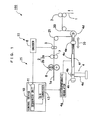
- FIG. 1 is a schematic view showing a feedback controlled tension applying system according to an embodiment of the present invention.
- the corrugated fin processing device 2 is constituted of a slit processing device 2a that separates the fin material 1 in two rows along a moving direction of the fin material 1 by a pair of cutters 7, and a corrugation processing device 2b that corrugates the fin material 1, which is separated in two, by a pair of corrugate cutters 8.
- the corrugated fin processing device 2 functions as a material processing unit of the present invention.
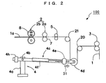
- a pulley 4d is rotatably provided on the other end portion of the arm 4c.
- a balance weight 4e is provided to be movable along and lockable on the arm 4c.
- the balance weight 4e is coupled to the piston rod of a piston, not shown, movable in the air cylinder 4f, and moves in one and the other directions on the arm 4c following extension and contraction of the piston rod with relative to the air cylinder 4f controlled by the control device 10, and thereafter locks at a desirable position.
- a fixed balance weight 4h for balancing the arm 4c is attached on the one side portion of the arm 4c.
- the sequencer unit 11 takes in the result of measuring the rotation angle of the measuring rolls 5 measured by the encoder 6.
- the moving length amount per predetermined time of the fin material 1 is calculated based on the measurement result of the encoder 6, the moving length amount per predetermined time of the fin material 1 is compared with a set value that is set in advance, and a digital control signal obtained by calculating the moving length amount per predetermined time of the fin material 1 to match the set value is converted by the D/A converter 13 into an analogue control signal so as to control the electropneumatic regulator 4g, thereby adjusting the air flow amount to be supplied to the air cylinder 4f.
- the electropneumatic regulator 4g adjusts the air flow amount in the air cylinder 4f to extend or contract the piston rod with relative to air cylinder 4f according to the analogue control signal. As a result, the balance weight 4e appropriately moves in a right and left directions on the arm 4c, thereby applying a predetermined tension to the fin material 1 through the pulley 4d of the arm 4c.
- the pulley 4d increases the tension in a longitudinal direction, namely, the moving direction of the fin material 1, so that the moving length amount per predetermined time of the fin material 1 to the downstream side is restrained in a direction to be small. Further, when the moving length amount per predetermined time of the fin material 1 is equal to or less than the set value, the balance weight 4e is moved so as to decrease the tension contrary to the above-mentioned case, thereby increasing the moving length amount per predetermined time of the fin material 1.
- control device 10 feedback-controls the tension applying device 4 based on the measurement result of the encoder 6 so that the moving length amount per predetermined time of the fin material 1 always becomes the set value that is set in advance, and adjusts the tension on the fin material 1 in real time.
- the moving length amount per predetermined time of the fin material 1 is measured by the encoder 6 and the tension on the fin material 1 is adjusted while feedback-controlling the tension applying device 4 based on the measurement result thereof, so that, when processing accuracy of the corrugate cutters 8 or the type or kind of the fin material 1 is changed, the moving length amount per predetermined time of the fin material 1 can be easily changed to supply a predetermined length amount per predetermined time of the fin material 1 to the corrugated fin processing device 2, thereby realizing formation of the corrugated fin 1a with high product precision.
- the feedback controlled tension applying system according to the embodiment of the present invention has been described above, but the specific structure of the present invention is not limited to the above-described embodiment.
- the present invention includes any change in design without departing from the gist of the invention.
- the example of the feedback controlled tension applying system 100 applied to the corrugated fin processing device 2 for heat exchangers has been described, but the invention is not limited to this, and it is needless to mention that the invention can be applied to, for example, a general roll forming device.
Landscapes
- Engineering & Computer Science (AREA)
- Mechanical Engineering (AREA)
- Controlling Rewinding, Feeding, Winding, Or Abnormalities Of Webs (AREA)
- Folding Of Thin Sheet-Like Materials, Special Discharging Devices, And Others (AREA)
Abstract
Description
Claims (4)
- A feedback controlled tension applying system (100), characterized in that it comprises:a material processing device (2) that processes a material (1) in continuous sheet form while applying a tension to the material (1);a tension applying device (4) that applies the tension to the material (1);a measuring means (22) for measuring a moving length amount per predetermined time of the material (1); anda control device (10) that feedback-controls said tension applying device (4) based on a measurement result of said measuring means (22) so that the moving length amount per predetermined time of the material (1) becomes a set value that is set in advance.
- The feedback controlled tension applying system (100) according to claim 1,
characterized in that said measuring means (22) comprises:characterized in that said measuring means (22) measures the moving length amount per predetermined time of the material (1) based on the amount regarding the rotation angle of said measuring roll (5) detected by said encoder (6).a measuring roll (5) that rotates in contact with the material (1); andan encoder (6) that detects an amount regarding a rotation angle of said measuring roll (5), and - The feedback controlled tension applying system (100) according to claim 1 or claim 2,
characterized in that said tension applying device (4) comprises:a base (4a);an arm (4c) having one and other end portions thereof, the one end portion of said arm (4c) being fixed to said base (4a) so as to be swingable in upward and downward directions and the other end portion of said arm (4c) being provided with a pulley (4d) that applies a load on the material (1); anda balance weight (4e) that moves on said arm (4c) in one and other directions along said arm (4c) by control of said control device (10). - The feedback controlled tension applying system (100) according to any one of claim 1 to claim 3,
characterized in that said material processing device (2) performs processing in a longitudinal direction of the material (1).
Applications Claiming Priority (2)
| Application Number | Priority Date | Filing Date | Title |
|---|---|---|---|
| JP2003013917A JP2004223565A (en) | 2003-01-22 | 2003-01-22 | Feedback tension unit |
| JP2003013917 | 2003-01-22 |
Publications (3)
| Publication Number | Publication Date |
|---|---|
| EP1440742A2 true EP1440742A2 (en) | 2004-07-28 |
| EP1440742A3 EP1440742A3 (en) | 2005-02-09 |
| EP1440742B1 EP1440742B1 (en) | 2006-05-24 |
Family
ID=32588647
Family Applications (1)
| Application Number | Title | Priority Date | Filing Date |
|---|---|---|---|
| EP04290165A Expired - Lifetime EP1440742B1 (en) | 2003-01-22 | 2004-01-22 | Feedback controlled tension applying system |
Country Status (4)
| Country | Link |
|---|---|
| US (1) | US6968254B2 (en) |
| EP (1) | EP1440742B1 (en) |
| JP (1) | JP2004223565A (en) |
| DE (1) | DE602004000916T2 (en) |
Cited By (1)
| Publication number | Priority date | Publication date | Assignee | Title |
|---|---|---|---|---|
| CN102674052A (en) * | 2011-03-10 | 2012-09-19 | 富士机械工业株式会社 | Coiling device and coiling control method |
Families Citing this family (11)
| Publication number | Priority date | Publication date | Assignee | Title |
|---|---|---|---|---|
| DE102005022238A1 (en) * | 2005-05-13 | 2006-11-16 | Emitec Gesellschaft Für Emissionstechnologie Mbh | Process to regulate production of a metallic foil with first and second stage tools and forming drum |
| JP4556966B2 (en) * | 2007-04-27 | 2010-10-06 | トヨタ自動車株式会社 | Web conveyance control method and conveyance control device |
| US7852021B2 (en) * | 2007-12-26 | 2010-12-14 | Pitney Bowes Inc. | Method and apparatus for minimizing forces on a web |
| CN103949516A (en) * | 2014-05-16 | 2014-07-30 | 吴江通信电缆厂 | Corrugating device for steel strip and aluminum strip |
| US9669952B2 (en) * | 2014-10-31 | 2017-06-06 | Tipper Tie, Inc. | Systems with wheel saddles that can cooperate with wheels of encoders and related devices and methods |
| CN113479692A (en) * | 2021-07-05 | 2021-10-08 | 绍兴马丁数码科技有限公司 | Loose centering machine |
| CN113548542B (en) * | 2021-07-12 | 2023-03-14 | 三一海洋重工有限公司 | Cable winding and unwinding control method, device and system for hoisting equipment |
| CN113666197B (en) * | 2021-10-21 | 2022-02-08 | 江苏安澜万锦电子股份有限公司 | Main shaft structure of taping machine and timing interruption control method thereof |
| CN113928892A (en) * | 2021-11-26 | 2022-01-14 | 金玻新材料技术有限公司 | Constant tension adjusting mechanism and control method thereof |
| DE112023006130T5 (en) * | 2023-04-03 | 2026-02-26 | Mitsubishi Electric Corporation | Conveying device, pressing device system and method for controlling a conveying device |
| CN121467828A (en) * | 2026-01-12 | 2026-02-06 | 泰州市江南机械制造有限公司 | A wire cutting machine tool with adaptive adjustment of wire pressure |
Family Cites Families (11)
| Publication number | Priority date | Publication date | Assignee | Title |
|---|---|---|---|---|
| US4775086A (en) * | 1985-08-27 | 1988-10-04 | Hiroshi Kataoka | Take-out/take-up tension control apparatus |
| US5146847A (en) * | 1991-04-01 | 1992-09-15 | General Motors Corporation | Variable speed feed control and tensioning of a bander |
| NL1000128C2 (en) * | 1995-04-12 | 1996-10-15 | Stork Contiweb | Method for calculating and controlling the elongation of a moving material web and device for applying the method. |
| US5813587A (en) * | 1995-10-03 | 1998-09-29 | Westvaco Corporation | Laminating machine register-length and web tension controller |
| JP3644121B2 (en) * | 1996-04-01 | 2005-04-27 | 株式会社デンソー | Corrugated fin forming apparatus and method |
| US5967445A (en) * | 1996-09-20 | 1999-10-19 | Kabushiki Kaisha Yuyama Seisakusho | Method of adjusting tension applied to sheet, and device for the same |
| US5809873A (en) * | 1996-11-18 | 1998-09-22 | Ovalstrapping, Inc. | Strapping machine having primary and secondary tensioning units and a control system therefor |
| JP3321051B2 (en) * | 1997-10-27 | 2002-09-03 | 川崎製鉄株式会社 | Method and apparatus for controlling shape of rolled material |
| JP2000343123A (en) * | 1999-06-03 | 2000-12-12 | Mitsubishi Electric Corp | Tension leveler |
| FR2806334B1 (en) * | 2000-03-15 | 2002-08-30 | L A Chaignaud Ets | BRAKING PRESS FOR HOT OR COLD ROLLED SHEET AND A BRAKING ASSEMBLY FOR SUCH A PRESS |
| JP4260350B2 (en) * | 2000-09-27 | 2009-04-30 | カルソニックカンセイ株式会社 | Corrugated fin manufacturing equipment |
-
2003
- 2003-01-22 JP JP2003013917A patent/JP2004223565A/en not_active Withdrawn
-
2004
- 2004-01-21 US US10/760,507 patent/US6968254B2/en not_active Expired - Fee Related
- 2004-01-22 EP EP04290165A patent/EP1440742B1/en not_active Expired - Lifetime
- 2004-01-22 DE DE602004000916T patent/DE602004000916T2/en not_active Expired - Fee Related
Cited By (2)
| Publication number | Priority date | Publication date | Assignee | Title |
|---|---|---|---|---|
| CN102674052A (en) * | 2011-03-10 | 2012-09-19 | 富士机械工业株式会社 | Coiling device and coiling control method |
| CN102674052B (en) * | 2011-03-10 | 2016-01-06 | 富士机械工业株式会社 | Wind2 and coiling controlling method |
Also Published As
| Publication number | Publication date |
|---|---|
| JP2004223565A (en) | 2004-08-12 |
| EP1440742A3 (en) | 2005-02-09 |
| EP1440742B1 (en) | 2006-05-24 |
| DE602004000916D1 (en) | 2006-06-29 |
| US6968254B2 (en) | 2005-11-22 |
| DE602004000916T2 (en) | 2006-12-21 |
| US20040153194A1 (en) | 2004-08-05 |
Similar Documents
| Publication | Publication Date | Title |
|---|---|---|
| EP1440742B1 (en) | Feedback controlled tension applying system | |
| EP0698752B1 (en) | Belt adjusting device and single facer | |
| US4061005A (en) | Method and apparatus for continuous bending of elongated materials | |
| US5413806A (en) | Strip coating machine with thickness control | |
| US4990079A (en) | Extrusion slot die with flexible lip | |
| AU627257B2 (en) | Apparatus for controlling the tilt angle of a doctor blade | |
| KR100818199B1 (en) | Cylindrical glass body manufacturing method and apparatus | |
| CN115308993B (en) | Nanoimprint device and method | |
| CN108290336A (en) | Film shaping device | |
| JPS63101028A (en) | Manufacturing device for corrugated fin | |
| JP4600664B2 (en) | Roll gap adjustment device | |
| US5626471A (en) | Adjustable hot gas torch nozzle | |
| CN1549752A (en) | Method and device for extruding curved extruded profiles | |
| US5628221A (en) | Fin mill machine | |
| JP4090083B2 (en) | Rolling mill shape control device | |
| JP2696299B2 (en) | Groove processing equipment | |
| US5957404A (en) | Ironing roll with cam for following coil/strip tangent point | |
| EP0775540A1 (en) | Fin mill machine | |
| JPH07214173A (en) | Control method of plate material handling robot hand for plate material bending machine | |
| WO2014136558A1 (en) | Braking device for steel material | |
| JPS63174709A (en) | Rolling mill control method | |
| JP2007203339A (en) | Feedback tension unit | |
| CN113084026B (en) | Section bar feeding equipment and method | |
| CN85103854A (en) | The guiding of paper in reel and the cancellation element that curls | |
| JP2575664Y2 (en) | Movement guide device having air pad with constant urging force |
Legal Events
| Date | Code | Title | Description |
|---|---|---|---|
| PUAI | Public reference made under article 153(3) epc to a published international application that has entered the european phase |
Free format text: ORIGINAL CODE: 0009012 |
|
| AK | Designated contracting states |
Kind code of ref document: A2 Designated state(s): AT BE BG CH CY CZ DE DK EE ES FI FR GB GR HU IE IT LI LU MC NL PT RO SE SI SK TR |
|
| AX | Request for extension of the european patent |
Extension state: AL LT LV MK |
|
| PUAL | Search report despatched |
Free format text: ORIGINAL CODE: 0009013 |
|
| AK | Designated contracting states |
Kind code of ref document: A3 Designated state(s): AT BE BG CH CY CZ DE DK EE ES FI FR GB GR HU IE IT LI LU MC NL PT RO SE SI SK TR |
|
| AX | Request for extension of the european patent |
Extension state: AL LT LV MK |
|
| RIC1 | Information provided on ipc code assigned before grant |
Ipc: 7B 21C 47/00 A Ipc: 7B 21D 13/04 B Ipc: 7B 65H 23/10 B |
|
| 17P | Request for examination filed |
Effective date: 20050729 |
|
| AKX | Designation fees paid |
Designated state(s): DE FR GB |
|
| GRAP | Despatch of communication of intention to grant a patent |
Free format text: ORIGINAL CODE: EPIDOSNIGR1 |
|
| GRAS | Grant fee paid |
Free format text: ORIGINAL CODE: EPIDOSNIGR3 |
|
| GRAA | (expected) grant |
Free format text: ORIGINAL CODE: 0009210 |
|
| AK | Designated contracting states |
Kind code of ref document: B1 Designated state(s): DE FR GB |
|
| REG | Reference to a national code |
Ref country code: GB Ref legal event code: FG4D |
|
| REF | Corresponds to: |
Ref document number: 602004000916 Country of ref document: DE Date of ref document: 20060629 Kind code of ref document: P |
|
| ET | Fr: translation filed | ||
| PLBE | No opposition filed within time limit |
Free format text: ORIGINAL CODE: 0009261 |
|
| STAA | Information on the status of an ep patent application or granted ep patent |
Free format text: STATUS: NO OPPOSITION FILED WITHIN TIME LIMIT |
|
| 26N | No opposition filed |
Effective date: 20070227 |
|
| PGFP | Annual fee paid to national office [announced via postgrant information from national office to epo] |
Ref country code: DE Payment date: 20080117 Year of fee payment: 5 Ref country code: GB Payment date: 20080116 Year of fee payment: 5 |
|
| PGFP | Annual fee paid to national office [announced via postgrant information from national office to epo] |
Ref country code: FR Payment date: 20080108 Year of fee payment: 5 |
|
| GBPC | Gb: european patent ceased through non-payment of renewal fee |
Effective date: 20090122 |
|
| PG25 | Lapsed in a contracting state [announced via postgrant information from national office to epo] |
Ref country code: DE Free format text: LAPSE BECAUSE OF NON-PAYMENT OF DUE FEES Effective date: 20090801 |
|
| REG | Reference to a national code |
Ref country code: FR Ref legal event code: ST Effective date: 20091030 |
|
| PG25 | Lapsed in a contracting state [announced via postgrant information from national office to epo] |
Ref country code: GB Free format text: LAPSE BECAUSE OF NON-PAYMENT OF DUE FEES Effective date: 20090122 |
|
| PG25 | Lapsed in a contracting state [announced via postgrant information from national office to epo] |
Ref country code: FR Free format text: LAPSE BECAUSE OF NON-PAYMENT OF DUE FEES Effective date: 20090202 |